EP3588515A1 - Drive device for incore nuclear instrumentation device - Google Patents
Drive device for incore nuclear instrumentation device Download PDFInfo
- Publication number
- EP3588515A1 EP3588515A1 EP17897470.5A EP17897470A EP3588515A1 EP 3588515 A1 EP3588515 A1 EP 3588515A1 EP 17897470 A EP17897470 A EP 17897470A EP 3588515 A1 EP3588515 A1 EP 3588515A1
- Authority
- EP
- European Patent Office
- Prior art keywords
- cover
- wall surface
- drive device
- safety circuit
- state
- Prior art date
- Legal status (The legal status is an assumption and is not a legal conclusion. Google has not performed a legal analysis and makes no representation as to the accuracy of the status listed.)
- Granted
Links
Images



Classifications
-
- F—MECHANICAL ENGINEERING; LIGHTING; HEATING; WEAPONS; BLASTING
- F16—ENGINEERING ELEMENTS AND UNITS; GENERAL MEASURES FOR PRODUCING AND MAINTAINING EFFECTIVE FUNCTIONING OF MACHINES OR INSTALLATIONS; THERMAL INSULATION IN GENERAL
- F16P—SAFETY DEVICES IN GENERAL; SAFETY DEVICES FOR PRESSES
- F16P1/00—Safety devices independent of the control and operation of any machine
- F16P1/02—Fixed screens or hoods
-
- F—MECHANICAL ENGINEERING; LIGHTING; HEATING; WEAPONS; BLASTING
- F16—ENGINEERING ELEMENTS AND UNITS; GENERAL MEASURES FOR PRODUCING AND MAINTAINING EFFECTIVE FUNCTIONING OF MACHINES OR INSTALLATIONS; THERMAL INSULATION IN GENERAL
- F16P—SAFETY DEVICES IN GENERAL; SAFETY DEVICES FOR PRESSES
- F16P3/00—Safety devices acting in conjunction with the control or operation of a machine; Control arrangements requiring the simultaneous use of two or more parts of the body
- F16P3/08—Safety devices acting in conjunction with the control or operation of a machine; Control arrangements requiring the simultaneous use of two or more parts of the body in connection with the locking of doors, covers, guards, or like members giving access to moving machine parts
-
- G—PHYSICS
- G21—NUCLEAR PHYSICS; NUCLEAR ENGINEERING
- G21C—NUCLEAR REACTORS
- G21C17/00—Monitoring; Testing ; Maintaining
- G21C17/10—Structural combination of fuel element, control rod, reactor core, or moderator structure with sensitive instruments, e.g. for measuring radioactivity, strain
-
- G—PHYSICS
- G21—NUCLEAR PHYSICS; NUCLEAR ENGINEERING
- G21C—NUCLEAR REACTORS
- G21C17/00—Monitoring; Testing ; Maintaining
- G21C17/10—Structural combination of fuel element, control rod, reactor core, or moderator structure with sensitive instruments, e.g. for measuring radioactivity, strain
- G21C17/108—Measuring reactor flux
-
- G—PHYSICS
- G21—NUCLEAR PHYSICS; NUCLEAR ENGINEERING
- G21C—NUCLEAR REACTORS
- G21C19/00—Arrangements for treating, for handling, or for facilitating the handling of, fuel or other materials which are used within the reactor, e.g. within its pressure vessel
- G21C19/20—Arrangements for introducing objects into the pressure vessel; Arrangements for handling objects within the pressure vessel; Arrangements for removing objects from the pressure vessel
-
- G—PHYSICS
- G21—NUCLEAR PHYSICS; NUCLEAR ENGINEERING
- G21C—NUCLEAR REACTORS
- G21C19/00—Arrangements for treating, for handling, or for facilitating the handling of, fuel or other materials which are used within the reactor, e.g. within its pressure vessel
- G21C19/20—Arrangements for introducing objects into the pressure vessel; Arrangements for handling objects within the pressure vessel; Arrangements for removing objects from the pressure vessel
- G21C19/207—Assembling, maintenance or repair of reactor components
-
- G—PHYSICS
- G21—NUCLEAR PHYSICS; NUCLEAR ENGINEERING
- G21C—NUCLEAR REACTORS
- G21C13/00—Pressure vessels; Containment vessels; Containment in general
- G21C13/02—Details
-
- Y—GENERAL TAGGING OF NEW TECHNOLOGICAL DEVELOPMENTS; GENERAL TAGGING OF CROSS-SECTIONAL TECHNOLOGIES SPANNING OVER SEVERAL SECTIONS OF THE IPC; TECHNICAL SUBJECTS COVERED BY FORMER USPC CROSS-REFERENCE ART COLLECTIONS [XRACs] AND DIGESTS
- Y02—TECHNOLOGIES OR APPLICATIONS FOR MITIGATION OR ADAPTATION AGAINST CLIMATE CHANGE
- Y02E—REDUCTION OF GREENHOUSE GAS [GHG] EMISSIONS, RELATED TO ENERGY GENERATION, TRANSMISSION OR DISTRIBUTION
- Y02E30/00—Energy generation of nuclear origin
- Y02E30/30—Nuclear fission reactors
Definitions
- the present invention relates to a drive device for an in-core neutron instrumentation system, for driving a neutron detector of the in-core neutron instrumentation system for measuring neutrons in a reactor of a nuclear power plant.
- the drive device can be driven at high speed even when the cover member is opened. Therefore, for example, at the time of maintenance and inspection of the conventional drive device, there has been a risk that the operator directly contacts the internal component during operation, resulting in accidents such as injuries and electric shocks.
- Patent Literature 1 JP-A-7-270580
- the conventional drive device for the in-core neutron instrumentation system is configured as described above, it has been capable of supplying (inputting) power to a drive motor and operating the drive device even during inspection work with the cover member removed.
- the drive device ensures a driving force by the drive motor. Further, in the conventional drive device, since it was possible to feed power to the drive motor even when the cover member is opened, the risk of electric shock due to the operator touching a charging unit of a power supply circuit or the like during power supply could not be ignored.
- the present invention has been made to solve the above problems, and an object of the present invention is to provide the drive device for the in-core neutron instrumentation system including a safety circuit for performing control to enable/disable power supply to the drive device for the in-core neutron instrumentation system depending on a mounted state of the cover member for covering the internal component of the drive device for the in-core neutron instrumentation system.
- a drive device for an in-core neutron instrumentation system drives a neutron detector of the in-core neutron instrumentation system for measuring neutrons in a nuclear reactor.
- the drive device for the in-core neutron instrumentation system includes: a winding drum for winding a cable having the neutron detector mounted at a tip end portion thereof; a drive motor for driving the winding drum for winding/extending the cable; a base member on which the winding drum and the drive motor are mounted; a cover member mounted on the base member and housing the winding drum and the drive motor therein; and a safety circuit provided between a power supply of the drive motor and the drive motor, and for switching between a conductive state in which power can be supplied to the drive motor and a cut-off state in which power cannot be supplied thereto depending on a mounted state of the cover member.
- the safety circuit enables switching between the conductive state in which power can be supplied to the drive motor and the cut-off state in which power cannot be supplied depending on the mounted state of the cover member. Therefore, it is possible to supply power to the drive device for the in-core neutron instrumentation system only when the safety circuit is in the conductive state.
- the in-core neutron instrumentation system for detecting neutron flux in a reactor is mainly constituted by a neutron detector, the drive device for the in-core neutron instrumentation system for driving the detector, and a control device for controlling them, and is supplied with power from an outside and operated.
- Fig. 1 is a perspective view showing an internal structure of a drive device 100 for the in-core neutron instrumentation system (hereinafter referred to as the drive device 100) according to Embodiment 1 of the present invention.
- the drive device 100 for moving a position of the neutron detector used for neutron measurement in a nuclear reactor of a nuclear power plant or the like is provided so that its external casing shape is, for example, a rectangular parallelepiped.
- Fig. 1 shows a state in which two front side portions of the four cover wall surface portions, and the cover upper surface portion constituting the cover member 8 are removed to expose the internal component.
- a drive cable 1 (drive cable) is in a state of being drawn out from a cable lead-out portion 1a of the drive device 100.
- the neutron detector (not shown) is attached to a tip end portion of the cable 1.
- the following components necessary for winding/extending the cable 1 are mounted on a mounting surface of the base member 9.
- a drive motor 3 converts electric power into power to drive a rotating shaft and rotates the drive wheel 2 interlocked with the rotating shaft.
- a winding drum 5 is a rotating body connected to the drive wheel 2 via a chain, and is a structure driven by the drive motor 3 in conjunction with the drive wheel 2 to wind the cable 1.
- a buffer coupling 6 is attached to the winding drum 5 and keeps the cable 1 stretched tight by always applying a constant tension in a direction opposite to an operation direction of the cable 1 by a restoring force of a spring, to prevent the cable 1 from being winded in disorder.
- the buffer coupling 6 is disclosed in detail in JP-A-1-185489 , JP-A-1-185490 and the like.
- the base member 9 is a substantially flat plate-like member including the mounting surface for mounting the internal component of the drive device 100.
- the base member 9 includes, as components, a rising surface portion 9a for fixing a safety circuit 10 described later and located at the other side surface lower portion of the exterior casing, and a rising surface portion 9b provided with the cable lead-out portion 1a for withdrawing the cable 1 and located at one side surface lower portion of the exterior casing.
- the base member 9 has a structure on which a functional portion of the drive device body is mounted.
- the safety circuit 10 incorporated in a power supply circuit of the drive motor 3 and for switching power supply enable/disable state to the drive motor 3 in combination with one surface of the cover member 8 is mounted on the drive device 100.
- the safety circuit 10 is in the cut-off state, even if power is supplied from the power supply or even if the operation of the drive device 100 is allowed (in the case of ON), it goes without saying that power is not supplied to the drive motor 3.
- the rising surface portions 9a and 9b can be formed integrally with the frame 7 which is a frame body for mounting the cover member 8 thereon.
- the safety circuit 10 is fixed to a portion which is not removed from the device body side of the drive device 100, and it may be fixedly used on the frame 7.
- the drive wheel 2 is provided with a spiral groove on its outer periphery.
- the groove of the drive wheel 2 meshes with a spiral structure of the outer periphery of the cable 1 wound on the winding drum 5, so that the cable 1 can be operated at a rotational speed of the drive motor 3 in a rotational direction of the drive motor 3.
- the safety circuit 10 is connected to an external power supply 20 via wiring 21, and the safety circuit 10 and the drive motor 3 are connected via wiring 22.
- Three wirings are shown corresponding to the fact that the power supply 20 is a three-phase AC power supply, however, it is also possible to arrange these three wires to be switched on and off collectively.
- Fig. 5 is a schematic diagram showing the drive device 100, shows an example of arrangement of cover wall surface portions 8a, 8b, 8c, 8d and a cover upper surface portion 8e constituting the cover member 8, and shows a connection state of wiring and the like from the power supply 20 to the drive motor 3.
- the power supply 20 and the drive device 100 are connected by a wiring 21a.
- the wiring 21a is drawn into the casing via a connector 25 from one surface of the cover member 8, and is connected to the safety circuit 10 via a wiring 21b applied to an inner surface of the cover member 8 or the base member 9.
- it is connected to a drive motor terminal box 26 of the drive motor 3 via the microswitch 12 and the wiring 22 in the safety circuit 10, and reaches the drive motor 3.
- FIG. 5 shows an example in which the connector 25 is disposed on the cover wall surface portion 8c, however, the present invention is not limited thereto.
- the safety circuit 10 when the cover member 8 is not mounted on the device body side, the power supply circuit is controlled to be cut off so that power cannot be supplied to the drive motor 3.
- the safety circuit 10 is switched to the cut-off state at a stage of removing the cover member 8. Therefore, the operator can safely perform maintenance work of the drive device 100 while avoiding risks such as contact and winding to an operation portion, and electric shock.
- the cover member 8 when the drive device 100 is in operation, since the cover member 8 is in the mounted state, it is possible to protect an interior of the drive device 100, thereby securing a stable operation state.
- Fig. 7 is an exploded perspective view of one cover locking mechanism portion 31, and shows an example of a shape of each portion.
- the cover locking mechanism portion 31 includes as components a body portion 32 mounted inside the frame 7, a first fitting pin 33 mounted on one panel of the cover member 8, for example, to an inner surface side contacting the frame 7 of the cover wall surface portion 8b, and a second fitting pin 34 mounted on an inner surface side contacting the frame 7 of the cover wall surface portion 8a adjacent to the cover wall surface portion 8b.
- the body portion 32 of the cover locking mechanism portion 31 is fixed so that a mounting surface portion on a side where the pressing plate 37 is provided is in contact with an inner surface side of the frame 7.
- An opening portion is provided in the frame 7, which enables access to the pressing plate 37 from the outside.
- the second fitting pin 34 fixed to project perpendicularly to a surface portion of the cover wall surface portion 8a is, for example, a member formed in a bar shape and machined to a size that can be inserted into the through-hole 33a of the first fitting pin 33.
- the second fitting pin 34 is inserted into an opening portion 35b connected to the opening portion 35a in the body portion 32 by mounting the cover wall surface portion 8a on the frame 7, and inserted into the through-hole 33a of the first fitting pin 33 in the opening portion 35a of the body portion 32, so that the first fitting pin 33 and the second fitting pin 34 are perpendicular to each other.
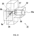
- Fig. 8 shows a configuration diagram of the cover locking mechanism portion 31 when both the cover wall surface portions 8a, 8b are mounted on the body portion 32 of the cover locking mechanism portion 31 fixed to the frame 7 (not shown).
- Fig. 8 shows a configuration diagram of the cover locking mechanism portion 31 when both the cover wall surface portions 8a, 8b are mounted on the body portion 32 of the cover locking mechanism portion 31 fixed to the frame 7 (not shown).
- the cover locking mechanism portion 31 having such a configuration to perform an operation in a manner that allows the cover wall surface portion 8b including the first fitting pin 33 to be first mounted on the frame 7, and then allows the cover wall surface portion 8a including the second fitting pin 34 to be next mounted on the frame 7.
- the mounting is performed in the reverse order, since there is a problem that the second fitting pin 34 interferes with the plunger 36 or the first fitting pin 33 interferes with the second fitting pin 34, both the cover wall portions 8a and 8b cannot be mounted.
- the cover member 8 When the cover member 8 is dismounted, it is possible to perform the operation in a manner of first removing the cover wall surface portion 8a including the second fitting pin 34, and next removing the cover wall surface portion 8b including the first fitting pin 33 from the frame 7. However, if the removal is performed in the reverse order, since the first fitting pin 33 in a state where the second fitting pin 34 is inserted through the through-hole 33a cannot be pulled out from the body portion 32, the cover wall surface portion 8b cannot be first removed from the device body portion.
- the safety circuit 10 is configured such that only the cover wall surface portion 8a (one surface) constituting the cover member 8 is a target of detection, and is configured to be interlocked only with the mounted state of the cover wall surface portion 8a.
- the safety circuit 10 is combined with the plurality of cover locking mechanism portions 31 to restrict the panel mounting order, so that one safe circuit 10 switches power supply enable/disable state to the drive motor 3.
- Fig. 9 is a configuration diagram showing the safety circuit 50 of the drive device 100 according to Embodiment 3.
- the microswitches 12 for cutting off the power supply circuit of the drive motor 3 are respectively provided on the surfaces of the cover wall surface portions 8a, 8b, 8c, 8d and the cover upper surface portion 8e constituting the cover member 8. That is, the surfaces of the cover wall surface portions 8a, 8b, 8c, 8d and the cover upper surface portion 8e are objects to be detected by the single safety circuit 10.
- a total of five safety circuits 10 are connected in series by wiring 23 so that a comprehensive safety circuit 50 is constructed.
- the safety circuits 10 are arranged in series, when any one of the safety circuits 10 detects the unmounted state of the cover member 8 to be detected, even if the other safety circuits 10 detect the mounted state, it is switched to the cut-off state by the comprehensive safety circuit 50, and power supply to the drive motor 3 is prohibited.
- the safety circuit 50 it is possible to obtain the drive device 100 with high safety capable of driving the drive motor 3 in response to all the panels of the cover member 8 being mounted.
- the drive device 100 in which one safety circuit 10 having only one cover wall surface portion 8a to be detected in the cover member 8 including the plurality of panels is provided is exemplified.
Landscapes
- Engineering & Computer Science (AREA)
- Physics & Mathematics (AREA)
- General Engineering & Computer Science (AREA)
- Plasma & Fusion (AREA)
- High Energy & Nuclear Physics (AREA)
- Mechanical Engineering (AREA)
- Monitoring And Testing Of Nuclear Reactors (AREA)
- Control Of Electric Motors In General (AREA)
Abstract
Description
- The present invention relates to a drive device for an in-core neutron instrumentation system, for driving a neutron detector of the in-core neutron instrumentation system for measuring neutrons in a reactor of a nuclear power plant.
- The conventional drive device for the in-core neutron instrumentation system (hereinafter simply referred to as the drive device) includes a mechanism portion for winding/extending a cable having a neutron detector fixed at a tip end portion thereof as an internal component. The drive device used a snap lock for fixing an exterior cover member thereof . The snap lock is a fixing member which fixes the cover member to a device body side so that the cover member is not opened by turning a lever by hooking an opposite side member to one protrusion.
- In the nuclear power plant, maintenance and inspection work is carried out approximately once a year. In the case where the cover member is fixed to the device body side by a method such as using the snap lock or a thumb screw, an operator can remove the cover member by a simple operation, access the internal component to perform maintenance work, and easily mount the cover member by a reverse procedure.
- Here, the drive device is a drive mechanism portion for moving the neutron detector fixed to the cable tip end portion at high speed. Therefore, a component rotates at high speed in the drive device during operation, and the cable is in a state to be wound/extended at high speed. The neutron detector moves from a standby installation position (an arbitrary position outside the reactor in a reactor containment vessel) to inside the reactor which is a measuring position (a distance between the two points is about 40 to 50 m) at the maximum speed of 36.6 m/min.
- In a conventional drive device, the drive device can be driven at high speed even when the cover member is opened. Therefore, for example, at the time of maintenance and inspection of the conventional drive device, there has been a risk that the operator directly contacts the internal component during operation, resulting in accidents such as injuries and electric shocks.
- Further, as a conventional technique, a device for cutting and collecting the cable has been proposed for collecting the cable of the drive device for the in-core neutron instrumentation system. At the time of cable collection, the drive device is configured to cut and collect the cable in a state in which the cover member is removed (for example, see Patent Literature 1).
- Patent Literature 1:
JP-A-7-270580 - Since the conventional drive device for the in-core neutron instrumentation system is configured as described above, it has been capable of supplying (inputting) power to a drive motor and operating the drive device even during inspection work with the cover member removed.
- Therefore, there has been the risk that the operator contacts the internal component of the drive device which is energized. The risk of maintenance and inspection work such that the operator contacts a cable winding drum or the like to be caught or contacts a rotating gear or the like to be injured during operation of the drive device could not be ignored.
- Further, the drive device ensures a driving force by the drive motor. Further, in the conventional drive device, since it was possible to feed power to the drive motor even when the cover member is opened, the risk of electric shock due to the operator touching a charging unit of a power supply circuit or the like during power supply could not be ignored.
- The present invention has been made to solve the above problems, and an object of the present invention is to provide the drive device for the in-core neutron instrumentation system including a safety circuit for performing control to enable/disable power supply to the drive device for the in-core neutron instrumentation system depending on a mounted state of the cover member for covering the internal component of the drive device for the in-core neutron instrumentation system.
- A drive device for an in-core neutron instrumentation system according to the present invention drives a neutron detector of the in-core neutron instrumentation system for measuring neutrons in a nuclear reactor. The drive device for the in-core neutron instrumentation system includes: a winding drum for winding a cable having the neutron detector mounted at a tip end portion thereof; a drive motor for driving the winding drum for winding/extending the cable; a base member on which the winding drum and the drive motor are mounted; a cover member mounted on the base member and housing the winding drum and the drive motor therein; and a safety circuit provided between a power supply of the drive motor and the drive motor, and for switching between a conductive state in which power can be supplied to the drive motor and a cut-off state in which power cannot be supplied thereto depending on a mounted state of the cover member.
- With the drive device for the in-core neutron instrumentation system of the present invention, the safety circuit enables switching between the conductive state in which power can be supplied to the drive motor and the cut-off state in which power cannot be supplied depending on the mounted state of the cover member. Therefore, it is possible to supply power to the drive device for the in-core neutron instrumentation system only when the safety circuit is in the conductive state.
-
- [
Fig. 1] Fig. 1 is a perspective view showing a drive device for an in-core neutron instrumentation system according toEmbodiment 1 of the present invention. - [
Fig. 2] Fig. 2 is a side cross-sectional view showing the drive device for the in-core neutron instrumentation system according toEmbodiment 1 of the present invention. - [
Fig. 3] Fig. 3 is an enlarged view of a main part showing a safety circuit of the drive device for the in-core neutron instrumentation system according toEmbodiment 1 of the present invention. - [
Fig. 4] Fig. 4 is a configuration diagram showing the safety circuit of the drive device for the in-core neutron instrumentation system according toEmbodiment 1 of the present invention. - [
Fig. 5] Fig. 5 is a configuration diagram showing the drive device for the in-core neutron instrumentation system according toEmbodiment 1 of the present invention. - [
Fig. 6] Fig. 6 is a perspective view showing the drive device for the in-core neutron instrumentation system according toEmbodiment 2 of the present invention. - [
Fig. 7] Fig. 7 is an exploded perspective view of a cover locking mechanism portion of the drive device for the in-core neutron instrumentation system according toEmbodiment 2 of the present invention. - [
Fig. 8] Fig. 8 is a perspective view of the cover locking mechanism portion of the drive device for the in-core neutron instrumentation system according toEmbodiment 2 of the present invention. - [
Fig. 9] Fig. 9 is a configuration diagram showing the safety circuit of the drive device for the in-core neutron instrumentation system according toEmbodiment 3 of the present invention. - Hereinafter, a drive device for an in-core neutron instrumentation system according to
Embodiment 1 of the present invention will be described with reference toFigs. 1 to 5 . - The in-core neutron instrumentation system for detecting neutron flux in a reactor is mainly constituted by a neutron detector, the drive device for the in-core neutron instrumentation system for driving the detector, and a control device for controlling them, and is supplied with power from an outside and operated.
-
Fig. 1 is a perspective view showing an internal structure of adrive device 100 for the in-core neutron instrumentation system (hereinafter referred to as the drive device 100) according toEmbodiment 1 of the present invention. - As shown in
Fig. 1 , thedrive device 100 for moving a position of the neutron detector used for neutron measurement in a nuclear reactor of a nuclear power plant or the like is provided so that its external casing shape is, for example, a rectangular parallelepiped. - A
base member 9 is provided as a base on which an internal component of the driving device is mounted. Panels (cover wall surface portions) are respectively provided so as to abut against four end sides of thebase member 9 having a substantially square planar shape. A panel (cover upper surface portion) is provided also over a space surrounded by the cover wall surface portions of four surfaces. Here, the panels are referred to as acover member 8 including the cover wall surface portions and the cover upper surface portion. -
Fig. 1 shows a state in which two front side portions of the four cover wall surface portions, and the cover upper surface portion constituting thecover member 8 are removed to expose the internal component. - Further, as shown in
Fig. 1 , a drive cable 1 (drive cable) is in a state of being drawn out from a cable lead-outportion 1a of thedrive device 100. The neutron detector (not shown) is attached to a tip end portion of thecable 1. - In order to move the neutron detector to an arbitrary position in the nuclear reactor, the following components necessary for winding/extending the
cable 1 are mounted on a mounting surface of thebase member 9. - A
drive wheel 2 is a rotating body which meshes with thecable 1, and allows thecable 1 to move back and forth according to its rotational direction. - A
drive motor 3 converts electric power into power to drive a rotating shaft and rotates thedrive wheel 2 interlocked with the rotating shaft. - A
brushless resolver 4 meshes with thedrive wheel 2 by a gear and detects a rotation angle of thedrive wheel 2 to measure a moving distance of thecable 1. - A
winding drum 5 is a rotating body connected to thedrive wheel 2 via a chain, and is a structure driven by thedrive motor 3 in conjunction with thedrive wheel 2 to wind thecable 1. - A
buffer coupling 6 is attached to thewinding drum 5 and keeps thecable 1 stretched tight by always applying a constant tension in a direction opposite to an operation direction of thecable 1 by a restoring force of a spring, to prevent thecable 1 from being winded in disorder. Thebuffer coupling 6 is disclosed in detail inJP-A-1-185489 JP-A-1-185490 - A
frame 7 is a member for fixing end portions of the panels constituting thecover member 8. Theframe 7 is provided in an abutting region between two adjacent cover wall surface portions, in an abutting region between the cover wall surface portion and the cover upper surface portion, and in an abutting region between the cover wall surface portion and thebase member 9, to hold the cover wall surface portions and the cover upper surface portion. - The
cover member 8 is an exterior casing including the cover wall surface portions mounted on thebase member 9, surrounding a periphery of thebase member 9, and extending upwardly, and the cover upper surface portion for covering a component mounting space over thebase member 9 surrounded by the cover wall surface portions. For example, thecover member 8 is not a component affecting an operation itself of a drive device body, but is used as a protective material for protecting the internal component and protecting an operator performing maintenance and inspection. - As described above, the
base member 9 is a substantially flat plate-like member including the mounting surface for mounting the internal component of thedrive device 100. For example, thebase member 9 includes, as components, a risingsurface portion 9a for fixing asafety circuit 10 described later and located at the other side surface lower portion of the exterior casing, and a risingsurface portion 9b provided with the cable lead-outportion 1a for withdrawing thecable 1 and located at one side surface lower portion of the exterior casing. As described above, thebase member 9 has a structure on which a functional portion of the drive device body is mounted. - The
safety circuit 10 incorporated in a power supply circuit of thedrive motor 3 and for switching power supply enable/disable state to thedrive motor 3 in combination with one surface of thecover member 8 is mounted on thedrive device 100. - The
safety circuit 10 is a component serving as a main portion of the present invention, and has a sensor unit (described later) fixed to thebase member 9 side (device body side) and detecting whether thecover member 8 is mounted on the device body side. - The
safety circuit 10 includes a circuit unit for switching to a conductive state in which power can be supplied to thedrive motor 3 when thecover member 8 is mounted, and for switching to a cut-off state in which power is cut off to thedrive motor 3 when thecover member 8 is not mounted, in response to a detection result of the sensor unit. - Even if the
safety circuit 10 is in the conductive state, when power is not supplied from a power supply or when an operation of thedrive device 100 is not allowed (in the case of OFF), power is not supplied to thedrive motor 3. - Further, if the
safety circuit 10 is in the cut-off state, even if power is supplied from the power supply or even if the operation of thedrive device 100 is allowed (in the case of ON), it goes without saying that power is not supplied to thedrive motor 3. - An example shown in
Fig. 1 shows a state in which thesafety circuit 10 is provided on the risingsurface portion 9a and the cable lead-outportion 1a is provided on the risingsurface portion 9b. However, both of the cable lead-outportion 1a and thesafety circuit 10 can be provided on either one of the risingsurface portions - Although main structural elements of the
drive device 100 according toEmbodiment 1 of the present invention have been described above, it goes without saying that there are cases where a component for assisting these functions or a component for adding another function is mounted thereon. -
Fig. 2 shows a side cross-sectional view (schematic view) in an extending direction of thecable 1 of thedrive device 100. As shown inFig. 2 , thebase member 9 includes risingsurface portions wall surface portions surface portions - Here, the
safety circuit 10 is fixed to the risingsurface portion 9a at one end of thebase member 9, and includes asensor unit 10a. Thesensor unit 10a is a component for detecting whether thecover member 8 is mounted on thebase member 9 side. As a detection method by thesensor unit 10a, it is possible to adopt various methods such as a method of detecting a mounted state by contacting a part of thesensor unit 10a with thecover member 8 which is an object to be detected, and a method of detecting the mounted state by closing of a lighting window by mounting of thecover member 8 by using a light detection unit. - Incidentally, the rising
surface portions frame 7 which is a frame body for mounting thecover member 8 thereon. - It is sufficient that the
safety circuit 10 is fixed to a portion which is not removed from the device body side of thedrive device 100, and it may be fixedly used on theframe 7. - Next, the operation of the
drive device 100 according toEmbodiment 1 of the present invention will be described. InFig. 1 , thedrive motor 3 is supplied with power from an external power supply, and can be operated, for example, under four conditions of forward rotation, reverse rotation, high speed, and low speed. As described above, rotational motion of thedrive motor 3 is transmitted to thedrive wheel 2 connected to thedrive motor 3, and the windingdrum 5 by the shaft, and thedrive wheel 2 and the windingdrum 5 synchronously rotate with thedrive motor 3. - Here, the
drive wheel 2 is provided with a spiral groove on its outer periphery. The groove of thedrive wheel 2 meshes with a spiral structure of the outer periphery of thecable 1 wound on the windingdrum 5, so that thecable 1 can be operated at a rotational speed of thedrive motor 3 in a rotational direction of thedrive motor 3. -
Fig. 3 shows an enlarged view of a main part of thesafety circuit 10.Fig. 3 corresponds to thesafety circuit 10 and its peripheral components surrounded by a dashed line inFig. 2 . As described above, as a structure of thesensor unit 10a which detects whether thecover member 8 is mounted, various types of configurations can be conceived. Here, a case where the detection is performed based on a projection state of a protuberance pressed against the object (cover member 8) to be detected will be exemplified. - A diagram on the left side of
Fig. 3 shows a state in which the coverwall surface portion 8a of thecover member 8 is not mounted on thebase member 9 side. At this time, since the coverwall surface portion 8a to be detected is not present, thesensor unit 10a (protuberance) of thesafety circuit 10 is in a state of largely protruding from a body portion of thesafety circuit 10, for example, in a state where a tip end of the protuberance projects to above the risingsurface portion 9a of thebase member 9. At this time, it is controlled to the cut-off state in which power cannot be supplied to thedrive motor 3, in thesafety circuit 10 in response to the state in which the coverwall surface portion 8a is not mounted. - A diagram on the right side of
Fig. 3 shows a state in which the coverwall surface portion 8a of thecover member 8 is mounted on thebase member 9 side. At this time, since the coverwall surface portion 8a to be detected is present, thesensor unit 10a (protuberance) of thesafety circuit 10 is in a state of hitting an inner wall of the coverwall surface portion 8a and being pushed back to the body portion side of thesafety circuit 10. At this time, it is controlled to the conductive state in which power can be supplied to thedrive motor 3, in thesafety circuit 10 in response to the state in which the coverwall surface portion 8a is mounted. -
Fig. 4 shows a configuration diagram of thesafety circuit 10 included in thedrive device 100 according toEmbodiment 1 of the present invention.Fig. 4 schematically shows the power supply circuit for supplying power to thedrive motor 3, and thesafety circuit 10 is provided in the circuit. - As shown in
Fig. 4 , thesafety circuit 10 is connected to anexternal power supply 20 viawiring 21, and thesafety circuit 10 and thedrive motor 3 are connected viawiring 22. Three wirings are shown corresponding to the fact that thepower supply 20 is a three-phase AC power supply, however, it is also possible to arrange these three wires to be switched on and off collectively. - The
safety circuit 10 has a microswitch 12 (for example, corresponding to thesensor unit 10a exemplified inFig. 3 ) which is operated only when the coverwall surface portion 8a constituting one surface of thecover member 8 is mounted on the device body side. When the cover member 8 (coverwall surface portion 8a) is mounted on thebase member 9 on the device body side, thesafety circuit 10 allows thepower supply 20 to supply power to thedrive motor 3. At this time, in the operation of themicroswitch 12, only the mounted state (mounted or not mounted) of thecover member 8 is a determination condition. Here, in the present invention, a special circuit such as a power supply monitoring circuit, and a control device are not required to determine whether power can be supplied to thedrive device 100. -
Fig. 5 is a schematic diagram showing thedrive device 100, shows an example of arrangement of coverwall surface portions upper surface portion 8e constituting thecover member 8, and shows a connection state of wiring and the like from thepower supply 20 to thedrive motor 3. - As shown in
Fig. 5 , thepower supply 20 and thedrive device 100 are connected by awiring 21a. Then, thewiring 21a is drawn into the casing via aconnector 25 from one surface of thecover member 8, and is connected to thesafety circuit 10 via awiring 21b applied to an inner surface of thecover member 8 or thebase member 9. Then, it is connected to a drivemotor terminal box 26 of thedrive motor 3 via themicroswitch 12 and thewiring 22 in thesafety circuit 10, and reaches thedrive motor 3.FIG. 5 shows an example in which theconnector 25 is disposed on the coverwall surface portion 8c, however, the present invention is not limited thereto. - As described above, in the
drive device 100 according toEmbodiment 1 of the present invention having thesafety circuit 10, when thecover member 8 is not mounted on the device body side, the power supply circuit is controlled to be cut off so that power cannot be supplied to thedrive motor 3. Thus, at the time of maintenance and inspection, thesafety circuit 10 is switched to the cut-off state at a stage of removing thecover member 8. Therefore, the operator can safely perform maintenance work of thedrive device 100 while avoiding risks such as contact and winding to an operation portion, and electric shock. Further, when thedrive device 100 is in operation, since thecover member 8 is in the mounted state, it is possible to protect an interior of thedrive device 100, thereby securing a stable operation state. - In the above-described
Embodiment 1, it has been described that it is controlled to switch whether to supply power to thedrive motor 3 using the mounted state (mounting/unmounting) of thecover member 8 as the determination condition in thesafety circuit 10. However, when thecover member 8 is composed of a plurality of panels and removal order of the plurality of panels is not restricted, themotor 3 is controlled regardless of the mounted state for panels which are not detected to be mounted/dismounted by thesafety circuit 10. - Therefore, in
Embodiment 2, thedrive device 100, which enables power supply from thedrive motor 3 in response to the mounted state of all the panels (coverwall surface portions upper surface portion 8e) constituting thecover member 8 on the device body side (base member 9 side), will be introduced. - The
drive device 100 according toEmbodiment 2 will be described with reference toFigs. 6 to 8 .Fig. 6 is a perspective view of thedrive device 100 according toEmbodiment 2, and is characterized in that coverlocking mechanism portions 31 for defining a panel mounting order of thecover member 8 composed of a plurality of parts is added, in contrast to the configuration shown inEmbodiment 1. - A body of the cover
locking mechanism portion 31 is fixed inside theframe 7 and is provided at a position accessible from two adjacent surfaces of thecover member 8. One coverlocking mechanism portion 31 defines the order of mounting and dismounting of two adjacent (abuttingly arranged) panels. Then, by adjusting arrangement of the coverlocking mechanism portions 31 so that any one of the coverlocking mechanism portions 31 distributed in theframe 7 has access from all the panels, the order of mounting and dismounting of all the panels can be restricted. Therefore, it is possible to allow the plurality of panels which is thecover member 8 to be mounted and dismounted according to a restricted order, and to prohibit mounting and dismounting in other than the restricted order. -
Fig. 7 is an exploded perspective view of one coverlocking mechanism portion 31, and shows an example of a shape of each portion. The coverlocking mechanism portion 31 includes as components abody portion 32 mounted inside theframe 7, a firstfitting pin 33 mounted on one panel of thecover member 8, for example, to an inner surface side contacting theframe 7 of the coverwall surface portion 8b, and a secondfitting pin 34 mounted on an inner surface side contacting theframe 7 of the coverwall surface portion 8a adjacent to the coverwall surface portion 8b. - The
body portion 32 of the coverlocking mechanism portion 31 has aplunger 36 disposed therein, and has anopening portion 35a for theplunger 36 to reciprocate linearly (for example, sliding movement or compression/decompression) in response to a pressing force from outside (the coverwall surface portion 8b). One end portion of theplunger 36 has apressing plate 37 against which the firstfitting pin 33 is pressed. - The
body portion 32 of the coverlocking mechanism portion 31 is fixed so that a mounting surface portion on a side where thepressing plate 37 is provided is in contact with an inner surface side of theframe 7. An opening portion is provided in theframe 7, which enables access to thepressing plate 37 from the outside. - As shown in
Fig. 7 , the firstfitting pin 33 fixed to project perpendicularly to a surface portion of the coverwall surface portion 8b is inserted into thebody portion 32 by mounting the coverwall surface portion 8b on theframe 7, and moves theplunger 36 by pushing thepressing plate 37 to a back side of theopening portion 35a. The firstfitting pin 33 is provided with a through-hole 33a through which the secondfitting pin 34 is inserted. - Further, the second
fitting pin 34 fixed to project perpendicularly to a surface portion of the coverwall surface portion 8a is, for example, a member formed in a bar shape and machined to a size that can be inserted into the through-hole 33a of the firstfitting pin 33. The secondfitting pin 34 is inserted into anopening portion 35b connected to theopening portion 35a in thebody portion 32 by mounting the coverwall surface portion 8a on theframe 7, and inserted into the through-hole 33a of the firstfitting pin 33 in theopening portion 35a of thebody portion 32, so that the firstfitting pin 33 and the secondfitting pin 34 are perpendicular to each other. -
Fig. 8 shows a configuration diagram of the coverlocking mechanism portion 31 when both the coverwall surface portions body portion 32 of the coverlocking mechanism portion 31 fixed to the frame 7 (not shown). As described above, in the present configuration, when the coverwall surface portion 8a is mounted after the coverwall surface portion 8b is mounted, it is possible to obtain a fitted state as shown inFig. 8 . Then, by removing the coverwall surface portion 8b after removing the coverwall surface portion 8a from a panel mounted state ofFig. 8 , it is possible to restore a panel unmounted state shown inFig. 7 . - When mounting the
cover member 8, it is possible for the coverlocking mechanism portion 31 having such a configuration to perform an operation in a manner that allows the coverwall surface portion 8b including the firstfitting pin 33 to be first mounted on theframe 7, and then allows the coverwall surface portion 8a including the secondfitting pin 34 to be next mounted on theframe 7. However, if the mounting is performed in the reverse order, since there is a problem that the secondfitting pin 34 interferes with theplunger 36 or the firstfitting pin 33 interferes with the secondfitting pin 34, both thecover wall portions - When the
cover member 8 is dismounted, it is possible to perform the operation in a manner of first removing the coverwall surface portion 8a including the secondfitting pin 34, and next removing the coverwall surface portion 8b including the firstfitting pin 33 from theframe 7. However, if the removal is performed in the reverse order, since the firstfitting pin 33 in a state where the secondfitting pin 34 is inserted through the through-hole 33a cannot be pulled out from thebody portion 32, the coverwall surface portion 8b cannot be first removed from the device body portion. - In this manner, by arranging the plurality of cover
locking mechanism portions 31 in consideration of the mounting order of the plurality of parts constituting thecover member 8 with respect to theframe 7 of thedrive device 100, it is possible to restrict the order of mounting so that the panel to be detected by thesafety circuit 10 is finally mounted on the device body side. As a result, even in the case where the number of thesafety circuits 10 is one, it is possible to control to the conductive state in which power can be supplied from the power supply only in a closed state in which all the panels of thecover member 8 are mounted. - Then, since the panels can be removed only in the reverse order of the mounting order, and removals in other orders are prohibited, when removing the
cover member 8, the panel to be detected by thesafety circuit 10 is first removed from the device body side, and it is possible to ensure safety of the operator. - In this manner, even in the case where one
safety circuit 10 is disposed for thedrive device 100, it is possible to ensure safety of the operator during maintenance and inspection by restricting the order of mounting each panel of thecover member 8. In addition, since the power supply to thedrive motor 3 is allowed only when all the panels constituting thecover member 8 are mounted, it is also possible to ensure a safe operation state of thedrive device 100. - In the above-described
Embodiment 1, thesafety circuit 10 is configured such that only the coverwall surface portion 8a (one surface) constituting thecover member 8 is a target of detection, and is configured to be interlocked only with the mounted state of the coverwall surface portion 8a. In the above-describedEmbodiment 2, thesafety circuit 10 is combined with the plurality of coverlocking mechanism portions 31 to restrict the panel mounting order, so that onesafe circuit 10 switches power supply enable/disable state to thedrive motor 3. - In contrast, in the
drive device 100 according toEmbodiment 3 of the present invention, safety circuits 10 (single safety circuit, series circuit) corresponding to the number of panels are respectively provided to be allocated to the panels so that each panel constituting thecover member 8 is to be detected, and control is performed using a safety circuit 50 (comprehensive safety circuit) connected in series. -
Fig. 9 is a configuration diagram showing thesafety circuit 50 of thedrive device 100 according toEmbodiment 3. Themicroswitches 12 for cutting off the power supply circuit of thedrive motor 3 are respectively provided on the surfaces of the coverwall surface portions upper surface portion 8e constituting thecover member 8. That is, the surfaces of the coverwall surface portions upper surface portion 8e are objects to be detected by thesingle safety circuit 10. Here, a total of fivesafety circuits 10 are connected in series by wiring 23 so that acomprehensive safety circuit 50 is constructed. - The
safety circuit 50 including this series circuit is controlled to be in the conductive state in response to all the panels constituting thecover member 8 being mounted on the device body side. - Since the
safety circuits 10 are arranged in series, when any one of thesafety circuits 10 detects the unmounted state of thecover member 8 to be detected, even if theother safety circuits 10 detect the mounted state, it is switched to the cut-off state by thecomprehensive safety circuit 50, and power supply to thedrive motor 3 is prohibited. - Therefore, by providing the
safety circuit 50, it is possible to obtain thedrive device 100 with high safety capable of driving thedrive motor 3 in response to all the panels of thecover member 8 being mounted. - In the above-described
Embodiment 1, thedrive device 100 in which onesafety circuit 10 having only one coverwall surface portion 8a to be detected in thecover member 8 including the plurality of panels is provided is exemplified. However, for example, it goes without saying that it is possible to obtain thedrive device 100 with higher safety by respectively providing thesafety circuits 10 for the plurality of panels (not all) constituting thecover member 8, to provide thesafety circuits 10 in series, and by combining the coverlocking mechanism portion 31 inEmbodiment 2. - Note that in the present invention, it is possible to freely combine each embodiment, or to deform or omit each embodiment as appropriate within the scope of the invention.
Claims (7)
- A drive device for an in-core neutron instrumentation system, the drive device driving a neutron detector of the in-core neutron instrumentation system for measuring neutrons in a nuclear reactor, comprising:a winding drum for winding a cable having the neutron detector mounted at a tip end portion thereof;a drive motor for driving the winding drum for winding/extending the cable;a base member on which the winding drum and the drive motor are mounted;a cover member mounted on the base member and housing the winding drum and the drive motor therein; anda safety circuit provided between a power supply of the drive motor and the drive motor, and for switching between a conductive state in which power can be supplied to the drive motor and a cut-off state in which power cannot be supplied thereto depending on a mounted state of the cover member.
- The drive device for the in-core neutron instrumentation system according to claim 1, wherein the safety circuit is controlled to be in the conductive state in response to a state in which the cover member is mounted on the base member, and is controlled to be in the cut-off state in response to a state in which the cover member is not mounted on the base member.
- The drive device for the in-core neutron instrumentation system according to claim 1 or 2, wherein the cover member comprises a plurality of cover wall surface portions surrounding a periphery of the base member, and is equipped with a cover locking mechanism portion for defining an order of mounting the cover wall surface portions on the base member.
- The drive device for the in-core neutron instrumentation system according to claim 3, wherein
the safety circuit is provided on one of the plurality of cover wall surface portions, and
the cover locking mechanism portion is provided so that the one cover wall surface portion on which the safety circuit is provided is finally mounted in the order of mounting the plurality of cover wall surface portions on the base member. - The drive device for the in-core neutron instrumentation system according to claim 3, wherein
the safety circuit is provided on one of the plurality of cover wall surface portions, and
the cover locking mechanism portion is provided so that the one cover wall surface portion on which the safety circuit is provided is first removed in an order of removing the plurality of cover wall surface portions from the base member. - The drive device for the in-core neutron instrumentation system according to any one of claims 3 to 5, wherein
the cover member comprises a cover upper surface portion for covering an upper portion of a space surrounded by the plurality of cover wall surface portions,
the cover wall surface portions and the cover upper surface portion are held by a frame which is fixed to the base member and provided in abutting regions between adjacent two of the cover wall surface portions and in abutting regions between the cover wall surface portions and the cover upper surface portion, and
the cover locking mechanism portion is mounted on the frame. - The drive device for the in-core neutron instrumentation system according to claim 1 or 2, wherein
the cover member comprises a plurality of cover wall surface portions surrounding a periphery of the base member and a cover upper surface portion for covering an upper portion of a space surrounded by the plurality of cover wall surface portions, and
the safety circuit is configured to include a series circuit which is brought into the conductive state in response to the whole cover member being mounted on the base member.
Applications Claiming Priority (1)
| Application Number | Priority Date | Filing Date | Title |
|---|---|---|---|
| PCT/JP2017/006729 WO2018154668A1 (en) | 2017-02-23 | 2017-02-23 | Drive device for incore nuclear instrumentation device |
Publications (3)
| Publication Number | Publication Date |
|---|---|
| EP3588515A1 true EP3588515A1 (en) | 2020-01-01 |
| EP3588515A4 EP3588515A4 (en) | 2020-01-01 |
| EP3588515B1 EP3588515B1 (en) | 2021-03-24 |
Family
ID=59720521
Family Applications (1)
| Application Number | Title | Priority Date | Filing Date |
|---|---|---|---|
| EP17897470.5A Active EP3588515B1 (en) | 2017-02-23 | 2017-02-23 | Drive device for incore nuclear instrumentation device |
Country Status (6)
| Country | Link |
|---|---|
| US (1) | US11069452B2 (en) |
| EP (1) | EP3588515B1 (en) |
| JP (1) | JP6190987B1 (en) |
| CN (1) | CN110326056B (en) |
| RU (1) | RU2715414C1 (en) |
| WO (1) | WO2018154668A1 (en) |
Family Cites Families (24)
| Publication number | Priority date | Publication date | Assignee | Title |
|---|---|---|---|---|
| JPS60242396A (en) * | 1985-05-09 | 1985-12-02 | 株式会社東芝 | Movable type neutron detector drive for nuclear reactor |
| JPS62142500U (en) | 1986-03-05 | 1987-09-08 | ||
| JPH0652317B2 (en) | 1988-01-20 | 1994-07-06 | 三菱電機株式会社 | Nuclear reactor core instrumentation equipment |
| JPH01185490A (en) | 1988-01-20 | 1989-07-25 | Mitsubishi Electric Corp | Reactor nuclear instrumentation device |
| JPH02271299A (en) * | 1989-04-13 | 1990-11-06 | Toshiba Corp | Driving device for detector |
| JPH07270580A (en) | 1994-03-30 | 1995-10-20 | Toshiba Eng Co Ltd | Mobile core monitor detector handling device |
| JPH09145887A (en) * | 1995-11-27 | 1997-06-06 | Hitachi Ltd | Mobile core instrumentation charge disconnect valve |
| US5870317A (en) * | 1997-05-21 | 1999-02-09 | Barnett; Ralph L. | Remote and proximal interlock testing mechanisms and testing systems |
| JP2000020174A (en) | 1998-06-30 | 2000-01-21 | Toshiba Corp | Power cutoff control device for electronic equipment |
| FR2812964B1 (en) * | 2000-08-11 | 2002-11-08 | Atea Soc Atlantique De Tech Av | DEVICE FOR LOCKING INSTRUMENT LINES OF THE CORE OF A PRESSURIZED WATER NUCLEAR REACTOR |
| JP2002071483A (en) * | 2000-08-31 | 2002-03-08 | Toshiba Corp | Mobile furnace instrumentation system torque measuring device |
| JP2005235730A (en) * | 2004-01-22 | 2005-09-02 | Fuji Electric Fa Components & Systems Co Ltd | Switch terminal device |
| RU2447959C2 (en) * | 2007-11-15 | 2012-04-20 | Сименс Фаи Металз Текнолоджиз Сас | Drive of rotation |
| CN101369724B (en) * | 2008-06-19 | 2011-03-23 | 山西全安新技术开发有限公司 | Leading uncovering power-off method and apparatus thereof |
| DE202010000032U1 (en) * | 2010-01-13 | 2011-03-10 | Krones Ag | Locking device and securing device for a working area of a machine |
| JP2012013546A (en) * | 2010-06-30 | 2012-01-19 | Toshiba Corp | Mobile type intra-furnace instrumentation driving device and method for monitoring frictional resistance of inside of guide pipe using the same |
| JP5898993B2 (en) * | 2011-03-15 | 2016-04-06 | 株式会社マキタ | Trigger switch for electric tools |
| US9943003B2 (en) * | 2012-06-25 | 2018-04-10 | Panduit Corp. | Electronics cabinet |
| JP5902602B2 (en) * | 2012-12-13 | 2016-04-13 | 株式会社東海理化電機製作所 | Locking device |
| CN103950785A (en) * | 2014-04-23 | 2014-07-30 | 山西太钢不锈钢股份有限公司 | Control device for preventing spool equipment cable falling |
| US9578772B2 (en) * | 2014-09-05 | 2017-02-21 | Emerson Network Power, Energy Systems, North America, Inc. | Cabinet frame enclosures, frame members and corresponding methods |
| DE102015113937A1 (en) * | 2015-08-21 | 2017-02-23 | Elobau Gmbh & Co. Kg | Wireless surveillance system |
| EP3345848B1 (en) * | 2017-01-04 | 2019-11-27 | OCE Holding B.V. | Drive gear assembly for a detachable roll |
| CN107767976B (en) * | 2017-10-17 | 2019-07-02 | 中国核动力研究设计院 | A kind of detector assembly dismounting technique and its dedicated dismounting equipment |
-
2017
- 2017-02-23 US US16/475,869 patent/US11069452B2/en active Active
- 2017-02-23 EP EP17897470.5A patent/EP3588515B1/en active Active
- 2017-02-23 RU RU2019129178A patent/RU2715414C1/en active
- 2017-02-23 CN CN201780086271.5A patent/CN110326056B/en active Active
- 2017-02-23 WO PCT/JP2017/006729 patent/WO2018154668A1/en not_active Ceased
- 2017-02-23 JP JP2017530103A patent/JP6190987B1/en active Active
Also Published As
| Publication number | Publication date |
|---|---|
| CN110326056B (en) | 2023-04-04 |
| WO2018154668A1 (en) | 2018-08-30 |
| RU2715414C1 (en) | 2020-02-28 |
| EP3588515B1 (en) | 2021-03-24 |
| CN110326056A (en) | 2019-10-11 |
| JP6190987B1 (en) | 2017-08-30 |
| US11069452B2 (en) | 2021-07-20 |
| EP3588515A4 (en) | 2020-01-01 |
| JPWO2018154668A1 (en) | 2019-02-28 |
| US20190378627A1 (en) | 2019-12-12 |
Similar Documents
| Publication | Publication Date | Title |
|---|---|---|
| KR101179080B1 (en) | Remote Control System for the Fuel Handling System of Nuclear Power Plant | |
| US10214952B2 (en) | Tubular drive apparatus | |
| US20140111144A1 (en) | Charge connector locking apparatus | |
| CN102684099A (en) | Withdrawable circuit breaker shutter systems | |
| CN103770934A (en) | Self-centering aircraft flap position command apparatus | |
| US8083525B2 (en) | Steering column module with a transport securing element | |
| US11069452B2 (en) | Drive device for in-core neutron instrumentation system | |
| US8988020B1 (en) | Motor operator system for a power switch with travel set with three positions for ground or double-throw type switch | |
| CN118762946B (en) | Electric power pressing plate | |
| CN214673893U (en) | A chassis car with counting function | |
| CN215221360U (en) | Safety locking device for cabinet door of power distribution cabinet | |
| CN222721352U (en) | Inverter with a power supply | |
| CN215866864U (en) | Novel stable high-voltage live display locking device | |
| CN224083819U (en) | A protective device for a dry-type transformer temperature controller | |
| CN223986154U (en) | Shielding cover with folding door assembly and wafer detection device | |
| CN221929116U (en) | Interlocking device for switch cabinet and switch cabinet | |
| CN106211679A (en) | A kind of safety cabinet door gear for regulator cubicle | |
| CN208077896U (en) | Earth leakage circuit breaker | |
| CN214507532U (en) | Electric control piano type operating table of motor | |
| CN212990300U (en) | Substation overhauls on-spot protection against electric shock warning device | |
| CN219997103U (en) | Analytical instrument, cover assembly and detection assembly for analytical instrument | |
| CN115175494B (en) | Electric power debugging device with leakage protection assembly | |
| CN219542821U (en) | Detection probe for machining | |
| CN222088448U (en) | Device is prevented bumping by mistake with button to tower machine switch board | |
| CN110676706A (en) | Power distribution cabinets, power distribution devices and inspection systems |
Legal Events
| Date | Code | Title | Description |
|---|---|---|---|
| STAA | Information on the status of an ep patent application or granted ep patent |
Free format text: STATUS: THE INTERNATIONAL PUBLICATION HAS BEEN MADE |
|
| PUAI | Public reference made under article 153(3) epc to a published international application that has entered the european phase |
Free format text: ORIGINAL CODE: 0009012 |
|
| STAA | Information on the status of an ep patent application or granted ep patent |
Free format text: STATUS: REQUEST FOR EXAMINATION WAS MADE |
|
| 17P | Request for examination filed |
Effective date: 20190522 |
|
| A4 | Supplementary search report drawn up and despatched |
Effective date: 20191204 |
|
| AK | Designated contracting states |
Kind code of ref document: A1 Designated state(s): AL AT BE BG CH CY CZ DE DK EE ES FI FR GB GR HR HU IE IS IT LI LT LU LV MC MK MT NL NO PL PT RO RS SE SI SK SM TR |
|
| AX | Request for extension of the european patent |
Extension state: BA ME |
|
| GRAP | Despatch of communication of intention to grant a patent |
Free format text: ORIGINAL CODE: EPIDOSNIGR1 |
|
| STAA | Information on the status of an ep patent application or granted ep patent |
Free format text: STATUS: GRANT OF PATENT IS INTENDED |
|
| RIC1 | Information provided on ipc code assigned before grant |
Ipc: G21C 19/20 20060101ALI20200331BHEP Ipc: G21C 17/108 20060101ALI20200331BHEP Ipc: F16P 1/02 20060101ALI20200331BHEP Ipc: G21C 17/10 20060101AFI20200331BHEP Ipc: F16P 3/08 20060101ALI20200331BHEP |
|
| DAV | Request for validation of the european patent (deleted) | ||
| DAX | Request for extension of the european patent (deleted) | ||
| INTG | Intention to grant announced |
Effective date: 20200415 |
|
| GRAJ | Information related to disapproval of communication of intention to grant by the applicant or resumption of examination proceedings by the epo deleted |
Free format text: ORIGINAL CODE: EPIDOSDIGR1 |
|
| STAA | Information on the status of an ep patent application or granted ep patent |
Free format text: STATUS: REQUEST FOR EXAMINATION WAS MADE |
|
| INTC | Intention to grant announced (deleted) | ||
| GRAP | Despatch of communication of intention to grant a patent |
Free format text: ORIGINAL CODE: EPIDOSNIGR1 |
|
| STAA | Information on the status of an ep patent application or granted ep patent |
Free format text: STATUS: GRANT OF PATENT IS INTENDED |
|
| INTG | Intention to grant announced |
Effective date: 20200909 |
|
| GRAS | Grant fee paid |
Free format text: ORIGINAL CODE: EPIDOSNIGR3 |
|
| GRAA | (expected) grant |
Free format text: ORIGINAL CODE: 0009210 |
|
| STAA | Information on the status of an ep patent application or granted ep patent |
Free format text: STATUS: THE PATENT HAS BEEN GRANTED |
|
| AK | Designated contracting states |
Kind code of ref document: B1 Designated state(s): AL AT BE BG CH CY CZ DE DK EE ES FI FR GB GR HR HU IE IS IT LI LT LU LV MC MK MT NL NO PL PT RO RS SE SI SK SM TR |
|
| REG | Reference to a national code |
Ref country code: GB Ref legal event code: FG4D |
|
| REG | Reference to a national code |
Ref country code: CH Ref legal event code: EP |
|
| REG | Reference to a national code |
Ref country code: IE Ref legal event code: FG4D |
|
| REG | Reference to a national code |
Ref country code: AT Ref legal event code: REF Ref document number: 1375322 Country of ref document: AT Kind code of ref document: T Effective date: 20210415 Ref country code: DE Ref legal event code: R096 Ref document number: 602017035479 Country of ref document: DE |
|
| REG | Reference to a national code |
Ref country code: SE Ref legal event code: TRGR |
|
| REG | Reference to a national code |
Ref country code: LT Ref legal event code: MG9D |
|
| PG25 | Lapsed in a contracting state [announced via postgrant information from national office to epo] |
Ref country code: NO Free format text: LAPSE BECAUSE OF FAILURE TO SUBMIT A TRANSLATION OF THE DESCRIPTION OR TO PAY THE FEE WITHIN THE PRESCRIBED TIME-LIMIT Effective date: 20210624 Ref country code: FI Free format text: LAPSE BECAUSE OF FAILURE TO SUBMIT A TRANSLATION OF THE DESCRIPTION OR TO PAY THE FEE WITHIN THE PRESCRIBED TIME-LIMIT Effective date: 20210324 Ref country code: GR Free format text: LAPSE BECAUSE OF FAILURE TO SUBMIT A TRANSLATION OF THE DESCRIPTION OR TO PAY THE FEE WITHIN THE PRESCRIBED TIME-LIMIT Effective date: 20210625 Ref country code: HR Free format text: LAPSE BECAUSE OF FAILURE TO SUBMIT A TRANSLATION OF THE DESCRIPTION OR TO PAY THE FEE WITHIN THE PRESCRIBED TIME-LIMIT Effective date: 20210324 Ref country code: BG Free format text: LAPSE BECAUSE OF FAILURE TO SUBMIT A TRANSLATION OF THE DESCRIPTION OR TO PAY THE FEE WITHIN THE PRESCRIBED TIME-LIMIT Effective date: 20210624 |
|
| PG25 | Lapsed in a contracting state [announced via postgrant information from national office to epo] |
Ref country code: RS Free format text: LAPSE BECAUSE OF FAILURE TO SUBMIT A TRANSLATION OF THE DESCRIPTION OR TO PAY THE FEE WITHIN THE PRESCRIBED TIME-LIMIT Effective date: 20210324 Ref country code: LV Free format text: LAPSE BECAUSE OF FAILURE TO SUBMIT A TRANSLATION OF THE DESCRIPTION OR TO PAY THE FEE WITHIN THE PRESCRIBED TIME-LIMIT Effective date: 20210324 |
|
| REG | Reference to a national code |
Ref country code: NL Ref legal event code: MP Effective date: 20210324 |
|
| REG | Reference to a national code |
Ref country code: AT Ref legal event code: MK05 Ref document number: 1375322 Country of ref document: AT Kind code of ref document: T Effective date: 20210324 |
|
| PG25 | Lapsed in a contracting state [announced via postgrant information from national office to epo] |
Ref country code: NL Free format text: LAPSE BECAUSE OF FAILURE TO SUBMIT A TRANSLATION OF THE DESCRIPTION OR TO PAY THE FEE WITHIN THE PRESCRIBED TIME-LIMIT Effective date: 20210324 |
|
| PG25 | Lapsed in a contracting state [announced via postgrant information from national office to epo] |
Ref country code: AT Free format text: LAPSE BECAUSE OF FAILURE TO SUBMIT A TRANSLATION OF THE DESCRIPTION OR TO PAY THE FEE WITHIN THE PRESCRIBED TIME-LIMIT Effective date: 20210324 Ref country code: SM Free format text: LAPSE BECAUSE OF FAILURE TO SUBMIT A TRANSLATION OF THE DESCRIPTION OR TO PAY THE FEE WITHIN THE PRESCRIBED TIME-LIMIT Effective date: 20210324 Ref country code: EE Free format text: LAPSE BECAUSE OF FAILURE TO SUBMIT A TRANSLATION OF THE DESCRIPTION OR TO PAY THE FEE WITHIN THE PRESCRIBED TIME-LIMIT Effective date: 20210324 Ref country code: CZ Free format text: LAPSE BECAUSE OF FAILURE TO SUBMIT A TRANSLATION OF THE DESCRIPTION OR TO PAY THE FEE WITHIN THE PRESCRIBED TIME-LIMIT Effective date: 20210324 Ref country code: LT Free format text: LAPSE BECAUSE OF FAILURE TO SUBMIT A TRANSLATION OF THE DESCRIPTION OR TO PAY THE FEE WITHIN THE PRESCRIBED TIME-LIMIT Effective date: 20210324 |
|
| PG25 | Lapsed in a contracting state [announced via postgrant information from national office to epo] |
Ref country code: IS Free format text: LAPSE BECAUSE OF FAILURE TO SUBMIT A TRANSLATION OF THE DESCRIPTION OR TO PAY THE FEE WITHIN THE PRESCRIBED TIME-LIMIT Effective date: 20210724 Ref country code: SK Free format text: LAPSE BECAUSE OF FAILURE TO SUBMIT A TRANSLATION OF THE DESCRIPTION OR TO PAY THE FEE WITHIN THE PRESCRIBED TIME-LIMIT Effective date: 20210324 Ref country code: RO Free format text: LAPSE BECAUSE OF FAILURE TO SUBMIT A TRANSLATION OF THE DESCRIPTION OR TO PAY THE FEE WITHIN THE PRESCRIBED TIME-LIMIT Effective date: 20210324 Ref country code: PT Free format text: LAPSE BECAUSE OF FAILURE TO SUBMIT A TRANSLATION OF THE DESCRIPTION OR TO PAY THE FEE WITHIN THE PRESCRIBED TIME-LIMIT Effective date: 20210726 Ref country code: PL Free format text: LAPSE BECAUSE OF FAILURE TO SUBMIT A TRANSLATION OF THE DESCRIPTION OR TO PAY THE FEE WITHIN THE PRESCRIBED TIME-LIMIT Effective date: 20210324 |
|
| REG | Reference to a national code |
Ref country code: DE Ref legal event code: R097 Ref document number: 602017035479 Country of ref document: DE |
|
| PG25 | Lapsed in a contracting state [announced via postgrant information from national office to epo] |
Ref country code: ES Free format text: LAPSE BECAUSE OF FAILURE TO SUBMIT A TRANSLATION OF THE DESCRIPTION OR TO PAY THE FEE WITHIN THE PRESCRIBED TIME-LIMIT Effective date: 20210324 Ref country code: AL Free format text: LAPSE BECAUSE OF FAILURE TO SUBMIT A TRANSLATION OF THE DESCRIPTION OR TO PAY THE FEE WITHIN THE PRESCRIBED TIME-LIMIT Effective date: 20210324 Ref country code: DK Free format text: LAPSE BECAUSE OF FAILURE TO SUBMIT A TRANSLATION OF THE DESCRIPTION OR TO PAY THE FEE WITHIN THE PRESCRIBED TIME-LIMIT Effective date: 20210324 |
|
| PLBE | No opposition filed within time limit |
Free format text: ORIGINAL CODE: 0009261 |
|
| STAA | Information on the status of an ep patent application or granted ep patent |
Free format text: STATUS: NO OPPOSITION FILED WITHIN TIME LIMIT |
|
| PG25 | Lapsed in a contracting state [announced via postgrant information from national office to epo] |
Ref country code: SI Free format text: LAPSE BECAUSE OF FAILURE TO SUBMIT A TRANSLATION OF THE DESCRIPTION OR TO PAY THE FEE WITHIN THE PRESCRIBED TIME-LIMIT Effective date: 20210324 |
|
| 26N | No opposition filed |
Effective date: 20220104 |
|
| PG25 | Lapsed in a contracting state [announced via postgrant information from national office to epo] |
Ref country code: IS Free format text: LAPSE BECAUSE OF FAILURE TO SUBMIT A TRANSLATION OF THE DESCRIPTION OR TO PAY THE FEE WITHIN THE PRESCRIBED TIME-LIMIT Effective date: 20210724 |
|
| REG | Reference to a national code |
Ref country code: DE Ref legal event code: R119 Ref document number: 602017035479 Country of ref document: DE |
|
| PG25 | Lapsed in a contracting state [announced via postgrant information from national office to epo] |
Ref country code: MC Free format text: LAPSE BECAUSE OF FAILURE TO SUBMIT A TRANSLATION OF THE DESCRIPTION OR TO PAY THE FEE WITHIN THE PRESCRIBED TIME-LIMIT Effective date: 20210324 |
|
| REG | Reference to a national code |
Ref country code: CH Ref legal event code: PL |
|
| REG | Reference to a national code |
Ref country code: BE Ref legal event code: MM Effective date: 20220228 |
|
| GBPC | Gb: european patent ceased through non-payment of renewal fee |
Effective date: 20220223 |
|
| PG25 | Lapsed in a contracting state [announced via postgrant information from national office to epo] |
Ref country code: LU Free format text: LAPSE BECAUSE OF NON-PAYMENT OF DUE FEES Effective date: 20220223 |
|
| PG25 | Lapsed in a contracting state [announced via postgrant information from national office to epo] |
Ref country code: FR Free format text: LAPSE BECAUSE OF NON-PAYMENT OF DUE FEES Effective date: 20220228 |
|
| PG25 | Lapsed in a contracting state [announced via postgrant information from national office to epo] |
Ref country code: LI Free format text: LAPSE BECAUSE OF NON-PAYMENT OF DUE FEES Effective date: 20220228 Ref country code: IT Free format text: LAPSE BECAUSE OF FAILURE TO SUBMIT A TRANSLATION OF THE DESCRIPTION OR TO PAY THE FEE WITHIN THE PRESCRIBED TIME-LIMIT Effective date: 20210324 Ref country code: IE Free format text: LAPSE BECAUSE OF NON-PAYMENT OF DUE FEES Effective date: 20220223 Ref country code: GB Free format text: LAPSE BECAUSE OF NON-PAYMENT OF DUE FEES Effective date: 20220223 Ref country code: DE Free format text: LAPSE BECAUSE OF NON-PAYMENT OF DUE FEES Effective date: 20220901 Ref country code: CH Free format text: LAPSE BECAUSE OF NON-PAYMENT OF DUE FEES Effective date: 20220228 |
|
| PG25 | Lapsed in a contracting state [announced via postgrant information from national office to epo] |
Ref country code: BE Free format text: LAPSE BECAUSE OF NON-PAYMENT OF DUE FEES Effective date: 20220228 |
|
| P01 | Opt-out of the competence of the unified patent court (upc) registered |
Effective date: 20230512 |
|
| PG25 | Lapsed in a contracting state [announced via postgrant information from national office to epo] |
Ref country code: MK Free format text: LAPSE BECAUSE OF FAILURE TO SUBMIT A TRANSLATION OF THE DESCRIPTION OR TO PAY THE FEE WITHIN THE PRESCRIBED TIME-LIMIT Effective date: 20210324 Ref country code: CY Free format text: LAPSE BECAUSE OF FAILURE TO SUBMIT A TRANSLATION OF THE DESCRIPTION OR TO PAY THE FEE WITHIN THE PRESCRIBED TIME-LIMIT Effective date: 20210324 |
|
| PG25 | Lapsed in a contracting state [announced via postgrant information from national office to epo] |
Ref country code: HU Free format text: LAPSE BECAUSE OF FAILURE TO SUBMIT A TRANSLATION OF THE DESCRIPTION OR TO PAY THE FEE WITHIN THE PRESCRIBED TIME-LIMIT; INVALID AB INITIO Effective date: 20170223 |
|
| PG25 | Lapsed in a contracting state [announced via postgrant information from national office to epo] |
Ref country code: TR Free format text: LAPSE BECAUSE OF FAILURE TO SUBMIT A TRANSLATION OF THE DESCRIPTION OR TO PAY THE FEE WITHIN THE PRESCRIBED TIME-LIMIT Effective date: 20210324 |
|
| PG25 | Lapsed in a contracting state [announced via postgrant information from national office to epo] |
Ref country code: MT Free format text: LAPSE BECAUSE OF FAILURE TO SUBMIT A TRANSLATION OF THE DESCRIPTION OR TO PAY THE FEE WITHIN THE PRESCRIBED TIME-LIMIT Effective date: 20210324 |
|
| PGFP | Annual fee paid to national office [announced via postgrant information from national office to epo] |
Ref country code: SE Payment date: 20250103 Year of fee payment: 9 |