EP3587977A1 - Rohr eines wärmetauschers und wärmetauscher mit solch einem rohr - Google Patents
Rohr eines wärmetauschers und wärmetauscher mit solch einem rohr Download PDFInfo
- Publication number
- EP3587977A1 EP3587977A1 EP18179906.5A EP18179906A EP3587977A1 EP 3587977 A1 EP3587977 A1 EP 3587977A1 EP 18179906 A EP18179906 A EP 18179906A EP 3587977 A1 EP3587977 A1 EP 3587977A1
- Authority
- EP
- European Patent Office
- Prior art keywords
- tube
- rank
- canal
- sheet
- side wall
- Prior art date
- Legal status (The legal status is an assumption and is not a legal conclusion. Google has not performed a legal analysis and makes no representation as to the accuracy of the status listed.)
- Withdrawn
Links
Images


Classifications
-
- F—MECHANICAL ENGINEERING; LIGHTING; HEATING; WEAPONS; BLASTING
- F28—HEAT EXCHANGE IN GENERAL
- F28F—DETAILS OF HEAT-EXCHANGE AND HEAT-TRANSFER APPARATUS, OF GENERAL APPLICATION
- F28F1/00—Tubular elements; Assemblies of tubular elements
- F28F1/02—Tubular elements of cross-section which is non-circular
- F28F1/022—Tubular elements of cross-section which is non-circular with multiple channels
-
- F—MECHANICAL ENGINEERING; LIGHTING; HEATING; WEAPONS; BLASTING
- F28—HEAT EXCHANGE IN GENERAL
- F28D—HEAT-EXCHANGE APPARATUS, NOT PROVIDED FOR IN ANOTHER SUBCLASS, IN WHICH THE HEAT-EXCHANGE MEDIA DO NOT COME INTO DIRECT CONTACT
- F28D1/00—Heat-exchange apparatus having stationary conduit assemblies for one heat-exchange medium only, the media being in contact with different sides of the conduit wall, in which the other heat-exchange medium is a large body of fluid, e.g. domestic or motor car radiators
- F28D1/02—Heat-exchange apparatus having stationary conduit assemblies for one heat-exchange medium only, the media being in contact with different sides of the conduit wall, in which the other heat-exchange medium is a large body of fluid, e.g. domestic or motor car radiators with heat-exchange conduits immersed in the body of fluid
- F28D1/03—Heat-exchange apparatus having stationary conduit assemblies for one heat-exchange medium only, the media being in contact with different sides of the conduit wall, in which the other heat-exchange medium is a large body of fluid, e.g. domestic or motor car radiators with heat-exchange conduits immersed in the body of fluid with plate-like or laminated conduits
- F28D1/0391—Heat-exchange apparatus having stationary conduit assemblies for one heat-exchange medium only, the media being in contact with different sides of the conduit wall, in which the other heat-exchange medium is a large body of fluid, e.g. domestic or motor car radiators with heat-exchange conduits immersed in the body of fluid with plate-like or laminated conduits a single plate being bent to form one or more conduits
-
- F—MECHANICAL ENGINEERING; LIGHTING; HEATING; WEAPONS; BLASTING
- F28—HEAT EXCHANGE IN GENERAL
- F28D—HEAT-EXCHANGE APPARATUS, NOT PROVIDED FOR IN ANOTHER SUBCLASS, IN WHICH THE HEAT-EXCHANGE MEDIA DO NOT COME INTO DIRECT CONTACT
- F28D1/00—Heat-exchange apparatus having stationary conduit assemblies for one heat-exchange medium only, the media being in contact with different sides of the conduit wall, in which the other heat-exchange medium is a large body of fluid, e.g. domestic or motor car radiators
- F28D1/02—Heat-exchange apparatus having stationary conduit assemblies for one heat-exchange medium only, the media being in contact with different sides of the conduit wall, in which the other heat-exchange medium is a large body of fluid, e.g. domestic or motor car radiators with heat-exchange conduits immersed in the body of fluid
- F28D1/04—Heat-exchange apparatus having stationary conduit assemblies for one heat-exchange medium only, the media being in contact with different sides of the conduit wall, in which the other heat-exchange medium is a large body of fluid, e.g. domestic or motor car radiators with heat-exchange conduits immersed in the body of fluid with tubular conduits
- F28D1/053—Heat-exchange apparatus having stationary conduit assemblies for one heat-exchange medium only, the media being in contact with different sides of the conduit wall, in which the other heat-exchange medium is a large body of fluid, e.g. domestic or motor car radiators with heat-exchange conduits immersed in the body of fluid with tubular conduits the conduits being straight
- F28D1/0535—Heat-exchange apparatus having stationary conduit assemblies for one heat-exchange medium only, the media being in contact with different sides of the conduit wall, in which the other heat-exchange medium is a large body of fluid, e.g. domestic or motor car radiators with heat-exchange conduits immersed in the body of fluid with tubular conduits the conduits being straight the conduits having a non-circular cross-section
- F28D1/05366—Assemblies of conduits connected to common headers, e.g. core type radiators
- F28D1/05383—Assemblies of conduits connected to common headers, e.g. core type radiators with multiple rows of conduits or with multi-channel conduits
-
- F—MECHANICAL ENGINEERING; LIGHTING; HEATING; WEAPONS; BLASTING
- F28—HEAT EXCHANGE IN GENERAL
- F28F—DETAILS OF HEAT-EXCHANGE AND HEAT-TRANSFER APPARATUS, OF GENERAL APPLICATION
- F28F2225/00—Reinforcing means
- F28F2225/04—Reinforcing means for conduits
-
- F—MECHANICAL ENGINEERING; LIGHTING; HEATING; WEAPONS; BLASTING
- F28—HEAT EXCHANGE IN GENERAL
- F28F—DETAILS OF HEAT-EXCHANGE AND HEAT-TRANSFER APPARATUS, OF GENERAL APPLICATION
- F28F2275/00—Fastening; Joining
- F28F2275/04—Fastening; Joining by brazing
Definitions
- the present invention concerns a tube of a heat exchanger for a refrigerant fluid circulation circuit fitted for an automotive vehicle.
- the object of the present invention is such a tube and a heat exchanger comprising at least one of these tubes.
- Another object of the invention is a method to obtain this tube.
- An automotive vehicle is currently equipped with a heating, ventilating and air conditioning system, usually called the HVAC system, for thermally treating the air present in or sent inside a passenger compartment of the automotive vehicle.
- the HVAC system is associated with a refrigerant fluid circulation circuit inside which a refrigerant fluid circulates.
- the refrigerant fluid circulation circuit comprises successively a compressor, a condenser or gas cooler, an expansion device and a heat exchanger.
- the heat exchanger is housed inside the HVAC system to allow a heat exchange between the refrigerant fluid and an air flow that is circulating inside the HVAC system before being delivered inside the passenger compartment.
- the heat exchanger is used as an evaporator to cool down the air flow.
- the refrigerant fluid is compressed inside the compressor, then the refrigerant fluid is cooled inside the condenser or gas cooler, then the refrigerant fluid expands within the expansion device and finally the refrigerant fluid cools down the air flow passing through the heat exchanger.
- the heat exchanger comprises two header boxes between which a bunch of tubes is interposed.
- the tubes are extended along a longitudinal direction that is perpendicular with the extension direction of both header boxes.
- the tubes are also laterally extended along a lateral direction that is perpendicular to a general plan of the heat exchanger containing the header boxes and the tubes.
- the tubes all together form a core that is globally arranged as a parallelepiped disposed between the header boxes.
- the core has two large faces the air flow is passing through, a first face being an inlet face of the core and a second face being an outlet face of the core. The air flow is entering the core through the inlet face and the air flow is exiting the core through the outlet face.
- the tubes are arranged so that a first lateral edge of each tube is located in the inlet face and a second lateral edge of the considered tube is located in the outlet face. Therefore, the tubes are disposed in respective plans that are parallel to a lateral plan, the lateral plan being perpendicular to the general plan of the heat exchanger.
- the first lateral edges of the tubes i.e the edge being located in the inlet face of the core, tend to be corroded more than the other parts of the tube. This corrosion may deteriorate the tube and some leaks of refrigerant fluid may appear which is mostly inconvenient.
- the tube of the invention is a tube of a heat exchanger, the tube extending mainly along a longitudinal direction and the tube extending between two opposite lateral edges of the tube.
- the tube comprises a plurality of canals that are parallel to the longitudinal direction.
- the tube comprises a single first rank canal that is delimited by at least a first lateral edge of the tube and two first rank side walls.
- the tube comprises at least a second rank canal that is delimited by at least two second rank side walls.
- a thickness of both first rank side walls of the first rank canal is bigger than a thickness of any second rank side wall of a second rank canal of the tube and wherein a thickness of the first lateral edge of the tube is bigger than a thickness of any second rank side wall of a second rank canal.
- the invention is also advantageously characterized by any of the following characteristics, these characteristics being combined or considered alone :
- the invention concerns also a heat exchanger comprising at least such a tube.
- the invention concerns also a refrigerant fluid circulation circuit comprising at least such a heat exchanger.
- the invention concerns also a utilization of this heat exchanger as an evaporator in such a refrigerant fluid circulation circuit.
- the invention concerns also a method for manufacturing such a tube, wherein the tube is realized by bending a sheet.
- Such a method comprises at least:
- a heat exchanger 1 according to the invention is shown in a coordinate system Oxyz in which Ox axis is a longitudinal axis, Oy axis is a lateral axis and Oz axis is a transversal axis, the Oxz plan is a longitudinal plan, the Oxy plan is a lateral plan and the Oyz plan is a transversal plan.
- a direction is qualified in accordance with the above mentioned axis and a surface is qualified in accordance with the above mentioned plan.
- a heat exchanger 1 comprises a core 2 disposed between two header boxes 3.
- the core 2 is the part of the heat exchanger 1 that is dedicated to enable a heat exchange between a refrigerant fluid 4 circulating in the heat exchanger 1 and an air flow 5 passing through the heat exchanger 1.
- Both header boxes 3 extend mainly in a transversal direction A1 that is parallel to the Oz axis.
- the core 2 comprises a plurality of tubes 6 that are interposed between the header boxes 3.
- the tubes 6 extend mainly along a longitudinal direction A2 that is parallel to the longitudinal axis Ox.
- the tubes 6 are also laterally extended along a lateral direction A3 that is parallel to the Oy axis.
- the lateral direction A3 is also perpendicular to a longitudinal plan P1 of the heat exchanger 1 containing the header boxes 3 and the tubes 6. Therefore, the tubes 6 are disposed in respective plans that are parallel to a lateral plan P2, the lateral plan P2 being perpendicular to the longitudinal plan P1 of the heat exchanger 1.
- the tubes 6 altogether form the core 2 that is globally arranged as a parallelepiped.
- the core 2 has two faces, usually the large faces of the parallelepiped, that are parallel to the longitudinal plan P1 and through which the air flow 5 is passing, a first face being an inlet face 11 of the core 2 and a second face being an outlet face 12 of the core 2.
- the air flow 5 is entering the core 2 through the inlet face 11 and the air flow 5 is exiting the core 2 through the outlet face 12, the air flow 5 flowing along the lateral direction.
- the inlet face 11 of the core 2 is an upstream face of the core 2 in comparison to the outlet face 12 of the core 2 that is a downstream face of the core 2 considering the sense of flowing of the air flow 5 through the core 2.
- Each tube 6 having a first longitudinal extremity 7 and a second longitudinal extremity 8 the tubes 6 have all their first longitudinal extremities 7 in fluidic communication with a first header box 3, for example a top header box, and have all their second longitudinal extremities 8 in fluidic communication with a second header box 3, for example the bottom header box.
- the longitudinal first extremity 7 and the second longitudinal extremity 8 form the longitudinal edges of the tube 6.
- the tube 6 is delimited by the two parallel longitudinal edges and two parallel lateral edges 21, 22 that are perpendicular to the longitudinal edges.
- the lateral edges 21, 22 are longer than the longitudinal edges.
- the tubes 6 are arranged so that a first lateral edge 21 of each tube 6 is located in the inlet face 11 and a second lateral edge 22 of the considered tube 6 is located in the outlet face 12. Therefore, the lateral edges 21, 22 of the tubes 6 delimit partially the core 2 and in particular the inlet face 11 and the outlet face 12.
- the first lateral edge 21 of a tube 6 is an upstream end of the tube 6 in comparison to the second lateral edge 22 of the tube 6 that is a downstream end of the tube 6 considering the flowing sense of the air flow 5 through the core 2.
- the heat exchanger 1 is equipped with a refrigerant fluid inlet 9 through which the refrigerant fluid 4 is admitted inside the heat exchanger 1.
- the refrigerant fluid inlet 9 equips the first header box 3.
- the heat exchanger 1 is also equipped with a refrigerant fluid outlet 10 through which the refrigerant fluid 4 is evacuated from the heat exchanger 1.
- the refrigerant fluid outlet 10 equips the second header box 3.
- the refrigerant fluid inlet 9 and the refrigerant fluid outlet 10 are located on the same longitudinal side of the heat exchanger 1. Therefore, in this embodiment of the invention, the refrigerant fluid 4 circulates along a path that is designed as a I form path. Other localization of the refrigerant fluid inlet 9 and the refrigerant fluid outlet 10 are possible, so that the heat exchanger 1 of the invention may provide a U form path or a W form path or other combinations of path for the refrigerant fluid 4.
- the core 2 comprises these tubes 6 and corrugated fins 14 that are separating two contiguous tubes 6, the corrugated fins 14 enhancing the heat exchange between the refrigerant fluid 4 and the air flow 5.
- Figure 2 illustrates a tube 6 of the heat exchanger 1 that comprises three canals 15a, 15b that are parallel to each other and to the longitudinal direction A2.
- the number of canals 15a, 15b can be different as soon as this number is greater than two.
- Each canal 15a, 15b is dedicated for the circulation of the refrigerant fluid 4 that is flowing from the first longitudinal extremity 7 to the second longitudinal extremity 8.
- the canals 15a, 15b of a tube 6 are interposed between the first lateral edge 21 of the considered tube 6 and the second lateral edge 22 of the considered tube 6.
- Each canal 15a, 15b has a cross section that is oblong.
- the first lateral edge 21 of the tube 6 is preferably rounded to facilitate a circulation of the air flow 5.
- a first rank canal 15a is partly delimited by the first lateral edge 21, i.e the upstream edge of the core 2.
- the first rank canal 15a is the one that is firstly in contact with the air flow 5 when the air flow 5 is entering the core 2 of the heat exchanger 1.
- a tube 6 comprises then a single first rank canal 15a and at least one second rank canal 15b, for example two second rank canals 15b as in the figured embodiment of the invention.
- the first rank canal 15a is the front canal and the second rank canals 15b are behind the first rank canal 15a.
- Each canal 15a, 15b is also delimited by two side walls 16a, 16b that are located in a respective plan parallel to the lateral plan P2. Side walls 16a, 16b of a considered canal 15a, 15b are facing each other. More particularly, the first rank canal 15a is delimited by two first rank side walls 16a and each second rank canal 15b is delimited by two second rank side walls 16b.
- each side wall 16a, 16b comprises an inner surface 17 facing the refrigerant fluid 4 and an outer surface 18 facing the external environment of the tube 6.
- the inner surface 17 is the surface of the canals 15a, 15b that is in contact with the refrigerant fluid 4 and the outer surface 18 is the surface of the canals 15a, 15b that is in contact with the air flow 5 and/or the corrugated fins 14.
- the present invention proposes that a thickness 19 of all first rank side walls 16a of the first rank canal 15a is bigger than a thickness 19 of any second rank side wall 16b of a second rank canal 15b of the tube 6.
- the present invention proposes also that a thickness 19 of the first lateral edge 21 of the tube 6 is bigger than a thickness 19 of any second rank side wall 16b of a second rank canal 15b.
- the thickness 19 of a side wall 16a, 16b is measured between the inner surface 17 and the outer surface 18 of the considered side wall 16a, 16b along a direction perpendicular to both surfaces 17, 18.
- the thickness 19 of any first rank side wall 16a of the first rank canal 15a is twice bigger than the thickness 19 of any second rank side wall 16b of a second rank canal 15b of the tube 6 and the thickness 19 of the first lateral edge 21 of the tube 6 is twice bigger than the thickness 19 of any second rank side wall 16b of a second rank canal 15b.
- any potential corrosion of the first rank side wall 16a of the first rank canal 15a is less likely to induce leaks of refrigerant fluid 4, which means that the tube 6 and the heat exchanger 1 comprising such a tube 6 is more robust than the heat exchanger of the prior art.
- Such a tube 6 can be obtained thanks to different methods.
- the tube 6 can be obtained by extrusion of an aluminum fused cast that passes through a grid comprising a pattern that is identical to the cross section of the tube featured in Figure 3 .
- the tube 6 can be obtained by joining two plates together along a joint plan that is identical to the lateral plan P2 featured in Figure 3 .
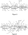
- the tube can be obtained by folding a single sheet 23 of a metallic material, aluminum for instance, in order to manufacture a tube 6 as featured in Figure 4 .
- the tube 6 represented in Figure 4 is issued from a single sheet 23 of material, such as the one represented in Figure 5 . In that case, the tube 6 is obtained from this sheet 23 without any over addition of pieces of material.
- both first rank side walls 16a of the first rank canal 15a are made from the same sheet 23.
- each side wall 16a is made of two folds 24a, 24b of the sheet 23.
- One of the folds 24a, 24b is an external fold 24a that is in contact with the air flow 5 or the corrugated fins 14 of the heat exchanger, the other of the folds 24a, 24b is an internal fold 24b which is in contact with the refrigerant fluid 4.
- the external fold 24a is overlapping the internal fold 24b.
- the sheet 23 is rectangular and comprises two longitudinal fringes 25 and two lateral fringes 26, the longitudinal fringes 25 being parallel to each other, and the longitudinal fringes 25 being also parallel to each other and perpendicular to the lateral fringes 26.
- the lateral fringes 26 are longer than the longitudinal fringes 25.
- the sheet 23 comprises a median longitudinal line 27 that is parallel to the longitudinal fringes 25 and that divides the sheet 23 in two equal portions 28.
- Each portion 28 comprises three longitudinal delimitating lines 29, 30 that are parallel to each other and parallel to the median longitudinal line 27.
- the delimitating lines 29, 30 are dividing each part in parts 31, 32 of equal surface.
- two external parts 32 are delimitated by one of the longitudinal fringes 25 and by an external delimitating line 30 that is the closest of the delimitating lines 29, 30 to the considered longitudinal fringe 25.
- four internal delimitating lines 29 and two external delimitating line 30 are illustrated that divide the sheet in eight parts 28 comprising two external parts 32 and six internal parts 31.
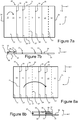
- Figures 6a and 6b illustrate a first step of the method for manufacturing the tube 6 from the sheet 23 in which grooves 33 are made along the internal delimitating lines 29.
- the grooves 33 are made by stamping one of the surfaces 34, 35 of the sheet. All the grooves 33 have a same depth and are preferably made between both lateral fringes 26. In another embodiment, the grooves 33 do not reach the lateral fringes 26, so that a space is let between the end of the groove 33 and the facing lateral fringe 26.
- Figures 7a and 7b illustrate a second step of the method for manufacturing the tube 6 from the sheet 23 in which a first external part 32 is bended at 180° over the contiguous internal part 31 along the external delimitating line 30, with providing a remaining space 36 between the first external part 32 and the internal part 31.
- Figure 7a illustrates the beginning of the second step
- Figure 7b illustrates the end of the second step.
- Figures 8a and 8b illustrate a third step of the method for manufacturing the tube 6 from the sheet 23 in which a first portion 28 of the sheet 23 is bended at 180° over a second portion 28 of the sheet 23 along the median longitudinal line 27, the grooves 33 of each portion 28 being in contact with the grooves 33 of the other portion 28.
- Figure 8a illustrates the beginning of the third step
- Figure 8b illustrates the end of the third step.
- Figures 9a and 9b illustrate a fourth step of the method for manufacturing the tube 6 from the sheet 23 in which a second external part 32 is bended at 180° over the portion 28 along the external delimitating line 30, with overlapping the first external part 32 and the facing internal part 31.
- Figure 9a illustrates the beginning of the second step
- Figure 9b illustrates the end of the second step.
- each ply 37 comprising a side wall 16a, 16b of each canal 15a, 15b and at least a groove 33 separating two contiguous canals 15a, 15b.
- a fifth step of the method for manufacturing the tube 6 from the sheet 23 is consisting in brazing the folded sheet 23 illustrated in Figure 9b in a furnace to obtain the tube 6.
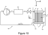
- FIG 10 illustrates a refrigerant fluid circulation circuit 100 inside which circulates the refrigerant fluid 4.
- the refrigerant fluid circulation circuit 100 successively comprises a compressor 101 for compressing the refrigerant fluid 4, a condenser or a gas cooler 102 for cooling the refrigerant 4, an expansion device 103 inside which the refrigerant fluid 4 expands and the heat exchanger 1.
- the heat exchanger 1 is accommodated inside an air duct 104 of a heating, ventilating and air conditioning system 105 inside which circulates the air flow 5.
- the heat exchanger 1 allows a heat transfer between the refrigerant fluid 4 and the air flow 5 coming into contact with it and/or passing through it, as illustrated in Figure 1 .
- the heat exchanger 1 is used as an evaporator for cooling the air flow 5, during the passage of the air flow 5 in contact with and/or from one side of the heat exchanger 1.
- the heat exchanger 1 is located in the air duct 104 in such a way that the inlet face 11 of the heat exchanger 1 that incorporates the first lateral edge 21 of the tubes 6 is an upstream face of the heat exchanger 1.
Priority Applications (4)
| Application Number | Priority Date | Filing Date | Title |
|---|---|---|---|
| EP18179906.5A EP3587977A1 (de) | 2018-06-26 | 2018-06-26 | Rohr eines wärmetauschers und wärmetauscher mit solch einem rohr |
| PCT/EP2019/064669 WO2020001948A1 (en) | 2018-06-26 | 2019-06-05 | Tube of a heat exchanger and heat exchanger comprising such a tube |
| US17/255,124 US20210270532A1 (en) | 2018-06-26 | 2019-06-05 | Tube of a heat exchanger and heat exchanger comprising such a tube |
| CN201980049792.2A CN112513552A (zh) | 2018-06-26 | 2019-06-05 | 热交换器的管以及包括这种管的热交换器 |
Applications Claiming Priority (1)
| Application Number | Priority Date | Filing Date | Title |
|---|---|---|---|
| EP18179906.5A EP3587977A1 (de) | 2018-06-26 | 2018-06-26 | Rohr eines wärmetauschers und wärmetauscher mit solch einem rohr |
Publications (1)
| Publication Number | Publication Date |
|---|---|
| EP3587977A1 true EP3587977A1 (de) | 2020-01-01 |
Family
ID=62791630
Family Applications (1)
| Application Number | Title | Priority Date | Filing Date |
|---|---|---|---|
| EP18179906.5A Withdrawn EP3587977A1 (de) | 2018-06-26 | 2018-06-26 | Rohr eines wärmetauschers und wärmetauscher mit solch einem rohr |
Country Status (4)
| Country | Link |
|---|---|
| US (1) | US20210270532A1 (de) |
| EP (1) | EP3587977A1 (de) |
| CN (1) | CN112513552A (de) |
| WO (1) | WO2020001948A1 (de) |
Citations (6)
| Publication number | Priority date | Publication date | Assignee | Title |
|---|---|---|---|---|
| GB2133525A (en) * | 1983-01-10 | 1984-07-25 | Nippon Denso Co | Heat exchange tube |
| US5185925A (en) * | 1992-01-29 | 1993-02-16 | General Motors Corporation | Method of manufacturing a tube for a heat exchanger |
| US20050092476A1 (en) * | 2003-10-31 | 2005-05-05 | Valeo Inc | Folded tube for a heat exchanger and method of making same |
| JP2009145020A (ja) * | 2007-12-18 | 2009-07-02 | Showa Denko Kk | 熱交換器用チューブ及びその製造方法並びに熱交換器 |
| US20100288481A1 (en) * | 2006-01-19 | 2010-11-18 | Werner Zobel | Flat tube, flat tube heat exchanger, and method of manufacturing same |
| DE102011008118A1 (de) * | 2011-01-07 | 2012-07-12 | Arup Alu-Rohr Und Profil Gmbh | Wärmetauscher sowie Mehrkammerflachrohr dafür |
Family Cites Families (4)
| Publication number | Priority date | Publication date | Assignee | Title |
|---|---|---|---|---|
| US6192977B1 (en) * | 1999-09-29 | 2001-02-27 | Valeo Thermique Moteur | Tube for heat exchanger |
| CN101405560B (zh) * | 2006-01-19 | 2011-06-08 | 摩丁制造公司 | 扁平管道、扁平管道热交换器及其制造方法 |
| JP5577616B2 (ja) * | 2009-04-06 | 2014-08-27 | 株式会社デンソー | 熱交換器用チューブ及び熱交換器 |
| DE102017201081A1 (de) * | 2016-01-25 | 2017-07-27 | Hanon Systems | Rohr für einen Wärmetauscher |
-
2018
- 2018-06-26 EP EP18179906.5A patent/EP3587977A1/de not_active Withdrawn
-
2019
- 2019-06-05 CN CN201980049792.2A patent/CN112513552A/zh active Pending
- 2019-06-05 US US17/255,124 patent/US20210270532A1/en not_active Abandoned
- 2019-06-05 WO PCT/EP2019/064669 patent/WO2020001948A1/en active Application Filing
Patent Citations (6)
| Publication number | Priority date | Publication date | Assignee | Title |
|---|---|---|---|---|
| GB2133525A (en) * | 1983-01-10 | 1984-07-25 | Nippon Denso Co | Heat exchange tube |
| US5185925A (en) * | 1992-01-29 | 1993-02-16 | General Motors Corporation | Method of manufacturing a tube for a heat exchanger |
| US20050092476A1 (en) * | 2003-10-31 | 2005-05-05 | Valeo Inc | Folded tube for a heat exchanger and method of making same |
| US20100288481A1 (en) * | 2006-01-19 | 2010-11-18 | Werner Zobel | Flat tube, flat tube heat exchanger, and method of manufacturing same |
| JP2009145020A (ja) * | 2007-12-18 | 2009-07-02 | Showa Denko Kk | 熱交換器用チューブ及びその製造方法並びに熱交換器 |
| DE102011008118A1 (de) * | 2011-01-07 | 2012-07-12 | Arup Alu-Rohr Und Profil Gmbh | Wärmetauscher sowie Mehrkammerflachrohr dafür |
Also Published As
| Publication number | Publication date |
|---|---|
| CN112513552A (zh) | 2021-03-16 |
| WO2020001948A1 (en) | 2020-01-02 |
| US20210270532A1 (en) | 2021-09-02 |
Similar Documents
| Publication | Publication Date | Title |
|---|---|---|
| JP5539742B2 (ja) | 熱交換器用の熱交換インサート | |
| WO2013168526A1 (ja) | 熱交換器および車両用空調装置 | |
| JPH04203895A (ja) | 熱交換器 | |
| JP2018025389A (ja) | 空調回路のための冷媒供給源を伴うコンデンサ | |
| WO2014041771A1 (ja) | 熱交換器 | |
| US20130255926A1 (en) | Heat exchanger and method of manufacturing the same | |
| US11384988B2 (en) | Heat exchanger | |
| US10969180B2 (en) | Air-conditioning unit | |
| JP5849883B2 (ja) | 蓄冷熱交換器 | |
| JP7047361B2 (ja) | 熱交換器 | |
| EP3587977A1 (de) | Rohr eines wärmetauschers und wärmetauscher mit solch einem rohr | |
| US20080245518A1 (en) | Flat Tube Making Platelike Body, Flat Tube, Heat Exchanger and Process for Fabricating Heat Exchanger | |
| JPH10217758A (ja) | 空調装置 | |
| US11662158B2 (en) | Heat exchanger plate and heat exchanger comprising such a heat exchanger plate | |
| JP5562769B2 (ja) | 熱交換器およびこれを備えた車両用空調装置 | |
| CN203719498U (zh) | 扁平状热交换管 | |
| JP5772608B2 (ja) | 熱交換器 | |
| CN109631454B (zh) | 冰箱 | |
| WO2022239173A1 (ja) | 鉄道車両用空調装置 | |
| EP3587980A1 (de) | Wärmetauscher für einen kühlflüssigkeitsströmungskreis | |
| JP2018096568A (ja) | 熱交換器 | |
| WO2024024394A1 (ja) | 熱交換器 | |
| WO2015098696A1 (ja) | 熱交換器 | |
| WO2021210428A1 (ja) | 熱交換器 | |
| JP5525805B2 (ja) | 熱交換器 |
Legal Events
| Date | Code | Title | Description |
|---|---|---|---|
| PUAI | Public reference made under article 153(3) epc to a published international application that has entered the european phase |
Free format text: ORIGINAL CODE: 0009012 |
|
| STAA | Information on the status of an ep patent application or granted ep patent |
Free format text: STATUS: THE APPLICATION HAS BEEN PUBLISHED |
|
| AK | Designated contracting states |
Kind code of ref document: A1 Designated state(s): AL AT BE BG CH CY CZ DE DK EE ES FI FR GB GR HR HU IE IS IT LI LT LU LV MC MK MT NL NO PL PT RO RS SE SI SK SM TR |
|
| AX | Request for extension of the european patent |
Extension state: BA ME |
|
| STAA | Information on the status of an ep patent application or granted ep patent |
Free format text: STATUS: REQUEST FOR EXAMINATION WAS MADE |
|
| STAA | Information on the status of an ep patent application or granted ep patent |
Free format text: STATUS: EXAMINATION IS IN PROGRESS |
|
| 17P | Request for examination filed |
Effective date: 20200701 |
|
| RBV | Designated contracting states (corrected) |
Designated state(s): AL AT BE BG CH CY CZ DE DK EE ES FI FR GB GR HR HU IE IS IT LI LT LU LV MC MK MT NL NO PL PT RO RS SE SI SK SM TR |
|
| 17Q | First examination report despatched |
Effective date: 20200728 |
|
| STAA | Information on the status of an ep patent application or granted ep patent |
Free format text: STATUS: EXAMINATION IS IN PROGRESS |
|
| STAA | Information on the status of an ep patent application or granted ep patent |
Free format text: STATUS: EXAMINATION IS IN PROGRESS |
|
| GRAP | Despatch of communication of intention to grant a patent |
Free format text: ORIGINAL CODE: EPIDOSNIGR1 |
|
| STAA | Information on the status of an ep patent application or granted ep patent |
Free format text: STATUS: GRANT OF PATENT IS INTENDED |
|
| INTG | Intention to grant announced |
Effective date: 20220413 |
|
| RAP3 | Party data changed (applicant data changed or rights of an application transferred) |
Owner name: VALEO VYMINIKY TEPLA, S.R.O. |
|
| STAA | Information on the status of an ep patent application or granted ep patent |
Free format text: STATUS: THE APPLICATION IS DEEMED TO BE WITHDRAWN |
|
| 18D | Application deemed to be withdrawn |
Effective date: 20220824 |