EP3587937A1 - Air conditioning indoor unit - Google Patents
Air conditioning indoor unit Download PDFInfo
- Publication number
- EP3587937A1 EP3587937A1 EP19182316.0A EP19182316A EP3587937A1 EP 3587937 A1 EP3587937 A1 EP 3587937A1 EP 19182316 A EP19182316 A EP 19182316A EP 3587937 A1 EP3587937 A1 EP 3587937A1
- Authority
- EP
- European Patent Office
- Prior art keywords
- end portion
- air
- outer circumferential
- flow fan
- cross flow
- Prior art date
- Legal status (The legal status is an assumption and is not a legal conclusion. Google has not performed a legal analysis and makes no representation as to the accuracy of the status listed.)
- Granted
Links
Images




Classifications
-
- F—MECHANICAL ENGINEERING; LIGHTING; HEATING; WEAPONS; BLASTING
- F24—HEATING; RANGES; VENTILATING
- F24F—AIR-CONDITIONING; AIR-HUMIDIFICATION; VENTILATION; USE OF AIR CURRENTS FOR SCREENING
- F24F1/00—Room units for air-conditioning, e.g. separate or self-contained units or units receiving primary air from a central station
- F24F1/0007—Indoor units, e.g. fan coil units
- F24F1/0018—Indoor units, e.g. fan coil units characterised by fans
- F24F1/0025—Cross-flow or tangential fans
-
- F—MECHANICAL ENGINEERING; LIGHTING; HEATING; WEAPONS; BLASTING
- F04—POSITIVE - DISPLACEMENT MACHINES FOR LIQUIDS; PUMPS FOR LIQUIDS OR ELASTIC FLUIDS
- F04D—NON-POSITIVE-DISPLACEMENT PUMPS
- F04D17/00—Radial-flow pumps, e.g. centrifugal pumps; Helico-centrifugal pumps
- F04D17/02—Radial-flow pumps, e.g. centrifugal pumps; Helico-centrifugal pumps having non-centrifugal stages, e.g. centripetal
- F04D17/04—Radial-flow pumps, e.g. centrifugal pumps; Helico-centrifugal pumps having non-centrifugal stages, e.g. centripetal of transverse-flow type
-
- F—MECHANICAL ENGINEERING; LIGHTING; HEATING; WEAPONS; BLASTING
- F04—POSITIVE - DISPLACEMENT MACHINES FOR LIQUIDS; PUMPS FOR LIQUIDS OR ELASTIC FLUIDS
- F04D—NON-POSITIVE-DISPLACEMENT PUMPS
- F04D29/00—Details, component parts, or accessories
- F04D29/40—Casings; Connections of working fluid
- F04D29/42—Casings; Connections of working fluid for radial or helico-centrifugal pumps
- F04D29/4206—Casings; Connections of working fluid for radial or helico-centrifugal pumps especially adapted for elastic fluid pumps
- F04D29/4226—Fan casings
-
- F—MECHANICAL ENGINEERING; LIGHTING; HEATING; WEAPONS; BLASTING
- F24—HEATING; RANGES; VENTILATING
- F24F—AIR-CONDITIONING; AIR-HUMIDIFICATION; VENTILATION; USE OF AIR CURRENTS FOR SCREENING
- F24F1/00—Room units for air-conditioning, e.g. separate or self-contained units or units receiving primary air from a central station
- F24F1/0007—Indoor units, e.g. fan coil units
- F24F1/0011—Indoor units, e.g. fan coil units characterised by air outlets
-
- F—MECHANICAL ENGINEERING; LIGHTING; HEATING; WEAPONS; BLASTING
- F24—HEATING; RANGES; VENTILATING
- F24F—AIR-CONDITIONING; AIR-HUMIDIFICATION; VENTILATION; USE OF AIR CURRENTS FOR SCREENING
- F24F13/00—Details common to, or for air-conditioning, air-humidification, ventilation or use of air currents for screening
- F24F13/08—Air-flow control members, e.g. louvres, grilles, flaps or guide plates
- F24F13/081—Air-flow control members, e.g. louvres, grilles, flaps or guide plates for guiding air around a curve
-
- F—MECHANICAL ENGINEERING; LIGHTING; HEATING; WEAPONS; BLASTING
- F24—HEATING; RANGES; VENTILATING
- F24F—AIR-CONDITIONING; AIR-HUMIDIFICATION; VENTILATION; USE OF AIR CURRENTS FOR SCREENING
- F24F13/00—Details common to, or for air-conditioning, air-humidification, ventilation or use of air currents for screening
- F24F13/24—Means for preventing or suppressing noise
-
- F—MECHANICAL ENGINEERING; LIGHTING; HEATING; WEAPONS; BLASTING
- F24—HEATING; RANGES; VENTILATING
- F24F—AIR-CONDITIONING; AIR-HUMIDIFICATION; VENTILATION; USE OF AIR CURRENTS FOR SCREENING
- F24F13/00—Details common to, or for air-conditioning, air-humidification, ventilation or use of air currents for screening
- F24F13/20—Casings or covers
Definitions
- the present invention relates to an air conditioning indoor unit.
- Japanese Unexamined Patent Application, First Publication No. 2015-190637 discloses an air conditioning indoor unit that includes a housing provided with an air inlet port and an air outlet port, an end portion casing, a cross flow fan, and a heat exchanger unit.
- the housing accommodates the end portion casing, the cross flow fan, and the heat exchanger unit.
- the end portion casing is disposed to face an outer circumferential surface of an end portion of the cross flow fan with a slight gap interposed therebetween.
- the end portion casing is provided for the purpose of suppressing indoor air flowing backward from the end portion of the cross flow fan.
- An outer circumferential surface of the cross flow fan includes a first outer circumferential surface corresponding to an air inflow region into which air sucked through the air inlet port flows and a second outer circumferential surface corresponding to an air outflow region from which air after heat exchange with the heat exchanger unit is blown toward the air outlet port.
- the present invention provides an air conditioning indoor unit with which it is possible to suppress generation of a blade passing frequency noise by suppressing inhibition against air blown from an outer circumferential surface of an end portion of a cross flow fan which is caused by an end portion casing.
- an air conditioning indoor unit including: a housing that is provided with an air inlet port through which indoor air is sucked and an air outlet port through which the air is blown outward; a heat exchange unit that is accommodated in the housing and performs heat exchange with the air sucked through the air inlet port; a cross flow fan that is accommodated in the housing, is disposed to extend in a width direction of the housing, and is provided with an outer circumferential surface, the outer circumferential surface including a first outer circumferential surface corresponding to an air inflow region into which the air after the heat exchange flows and a second outer circumferential surface corresponding to an air outflow region from which the air after the heat exchange flows out; a rear guider that is accommodated in the housing and is disposed close to a rear surface of the housing; a stabilizer that is accommodated in the housing, is disposed close to a front surface of the rear guider, and defines an air outlet flow path that communicates with the air outlet port and through which the air
- the second gap which is formed between the second outer circumferential surface corresponding to the air outflow region and the second inner surface of the second portion constituting the end portion casing is made wider than the first gap, which is formed between the first outer circumferential surface corresponding to the air inflow region and the first inner surface of the first portion constituting the end portion casing. Therefore, it is possible to reduce a possibility that the second portion inhibits a flow of air blown from the second outer circumferential surface positioned at the end portion of the cross flow fan.
- the second inner surface may be an inclined surface that is inclined in a direction away from a central axis of the cross flow fan.
- the second inner surface is an inclined surface that is inclined in a direction away from the central axis of the cross flow fan as described above, the second gap can be made wider than the first gap and air blown from the end portion of the cross flow fan can be guided in a direction toward the center of the cross flow fan.
- the rear guider may be provided with a first end portion positioned on the air outlet port side and a second end portion positioned opposite to the first end portion, the second end portion may be connected to a portion of the end portion casing that corresponds to a boundary between the air inflow region and the air outflow region, and the inclined surface may include a first inclined surface that is disposed on the second end portion side and of which an angle of inclination with respect to the central axis gradually increases toward the first end portion from the second end portion and a second inclined surface that is disposed on the first end portion side, that is integrated with the first inclined surface, and of which an angle of inclination with respect to the central axis is constant.
- an inclined surface which is the second inner surface includes the first inclined surface of which the angle of inclination with respect to the central axis gradually increases and the second inclined surface which is integrated with the first inclined surface and of which the angle of inclination with respect to the central axis is constant as described above, air flowing out from the second outer circumferential surface of the end portion of the cross flow fan can be smoothly guided in a direction toward the air outlet port.
- a level difference may be formed in a boundary between the second inclined surface and the first inner surface, an end portion of the stabilizer that is positioned opposite to an end portion positioned on the air outlet port side may be provided with a tongue portion, the tongue portion may have a shape alleviating the level difference, and a portion of the tongue portion may be disposed to extend at the level difference.
- the portion of the tongue portion that has the shape alleviating of the level difference is disposed at the level difference, the level difference formed in the boundary between the second inclined surface and the first inner surface can be decreased. Accordingly, it is possible to suppress turbulence which occurs when air flowing out from the cross flow fan collides with the level difference.
- FIG. 1 An air conditioning indoor unit 10 according to an embodiment will be described with reference to FIGS. 1 to 8 .
- "X" represents a width direction of a housing 11 and "O" represents a central axis (hereinafter, referred to as "central axis O") of a cross flow fan 15.
- a direction Z is a height direction (perpendicular direction) of the housing 11 which is orthogonal to a direction X.
- a direction Y is a depth direction of the housing 11 which is orthogonal to the direction X and the direction Z shown in FIG. 1 .
- FIGS. 4 to 7 a section on a stabilizer 18 side is illustrated to be positioned on a lower side in the drawings.
- FIGS. 1 to 8 the same components are given the same reference numerals.
- the air conditioning indoor unit 10 includes the housing 11, a heat exchange unit 13, the cross flow fan 15, a bearing portion 16, a rear guider 17, the stabilizer 18, an air outlet flow path 19, a motor 20, end portion casings 21 and 22, and upper and lower wind directing plates 24.
- the housing 11 has a hollow portion inside thereof and the housing 11 extends in the direction X.
- the housing 11 is provided with an air inlet port 11A and an air outlet port 11B.
- the air inlet port 11A is disposed close to an upper surface of the housing 11 (disposed on one side in direction Z).
- the air inlet port 11A is used when air in an indoor place where the air conditioning indoor unit 10 is disposed is sucked into the housing 11.
- the air outlet port 11B is disposed close to a lower surface of the housing 11 (disposed on other side in direction Z).
- the air outlet port 11B is an opening portion that is used when air after heat exchange flowing out from the cross flow fan 15 is discharged to the indoor place.
- the heat exchange unit 13 is accommodated in the housing 11 and a plurality of heat exchangers constitute the heat exchange unit 13.
- the heat exchange unit 13 is provided at a position separated from the cross flow fan 15.
- the heat exchange unit 13 has a U-like shape.
- the heat exchange unit 13 is disposed to surround a first outer circumferential surface 31b (outer circumferential surface corresponding to air inflow region 31A) of the cross flow fan 15.
- the heat exchange unit 13 performs heat exchange between indoor air sucked through the air inlet port 11A and a coolant flowing through a pipe of the heat exchange unit 13.
- the cross flow fan 15 is accommodated in the housing 11.
- the cross flow fan 15 includes a cross flow fan main body 31, a shaft portion 32, and a shaft accommodation portion 34.
- the cross flow fan main body 31 has a columnar shape and is disposed to extend in the direction X.
- the cross flow fan main body 31 is provided with the air inflow region 31A into which the air after the heat exchange flows, an air outflow region 31B from which the air after the heat exchange flows out, an outer circumferential surface 31a, and end portions 31C and 31D arranged in the direction X.
- the air inflow region 31A is a region facing the heat exchange unit 13.
- the air outflow region 31B is a region exposed to the air outlet flow path 19 defined by the rear guider 17 and the stabilizer 18.
- the outer circumferential surface 31a includes the first outer circumferential surface 31b and a second outer circumferential surface 31c.
- the first outer circumferential surface 31b is an outer circumferential surface, which is a portion of the outer circumferential surface 31a that corresponds to the air inflow region 31A.
- the second outer circumferential surface 31c is an outer circumferential surface, which is a portion of the outer circumferential surface 31a that corresponds to the air outflow region 31B.
- the end portions 31C and 310 include the above-described first and second outer circumferential surfaces 31b and 31c.
- the end portion 31C is an end portion disposed on the bearing portion 16 side.
- the end portion 31D is an end portion disposed on the motor 20 side.
- the shaft portion 32 is provided to protrude in the direction X from an end surface (end surface disposed on bearing portion 16 side) positioned on one side in the direction X.
- the shaft accommodation portion 34 is a recess portion formed close to an end surface (end surface disposed on motor 20 side) positioned on the other side in the direction X.
- the shaft accommodation portion 34 is formed to extend in the direction X toward the shaft portion 32.
- the bearing portion 16 is accommodated in the housing 11.
- the bearing portion 16 rotatably supports the shaft portion 32.
- the rear guider 17 is accommodated in the housing 11.
- the rear guider 17 is disposed close to a rear surface of the housing 11.
- the rear guider 17 has a curved shape that protrudes toward the rear surface of the housing 11.
- a surface 17a of the rear guider 17 that is positioned on the stabilizer 18 side is a curved surface.
- the rear guider 17 is provided with a first end portion 17A (lower end portion) positioned on the air outlet port 11B side and a second end portion 17B positioned opposite to the first end portion 17A.
- the first end portion 17A is connected to a portion of the housing 11 that is positioned close to the rear surface of the housing 11, the housing 11 defining the air outlet port 11B.
- the second end portion 17B is connected to portions of the end portion casings 21 and 22 that are at a boundary between the air inflow region 31A and the air outflow region 3 1B.
- the stabilizer 18 is accommodated in the housing 11.
- the stabilizer 18 is provided with a tongue portion 37 constituting one end portion 18A, the other end portion 18B, and a surface 18a.
- the tongue portion 37 is disposed in a state of inclined with respect to a portion of the stabilizer 18 other than the tongue portion 37 while being inclined toward the air inlet port 11A side.
- the tongue portion 37 is connected to the end portion casings 21 and 22. Note that, the details of a position where the tongue portion 37 is connected to the end portion casing 22 will be described later.
- the tongue portion 37 has a function of suppressing generation of a wind noise (blade passing frequency noise) which is caused by interference between an air vortex and blades of the cross flow fan 15.
- the other end portion 18B is connected to a portion of the housing 11 that is positioned close to a front surface of the housing 11, the housing 11 defining the air outlet port 11B.
- the surface 18a is a surface disposed on the rear guider 17 side.
- the surface 18a is disposed to be separated from the surface 17a in the direction Y.
- the air outlet flow path 19 is a flow path formed between the surface 17a of the rear guider 17 and the surface 18a of the stabilizer 18.
- the motor 20 is accommodated in the housing 11.
- the motor 20 includes a motor main body 20A and a motor shaft 20B.
- the motor main body 20A is supported by a supporting member (not shown).
- the motor shaft 20B is connected to the motor main body 20A and extends in the direction X.
- the motor shaft 20B is fixed to the cross flow fan main body 31 in a state of being accommodated in the shaft accommodation portion 34.
- the motor 20 is a drive unit for rotation of the cross flow fan 15.
- the end portion casing 21 is accommodated in the housing 11.
- the end portion casing 21 is supported by a supporting member (not shown).
- the end portion casing 21 is provided with a circular portion 41 and a cylindrical portion 42. In the center of the circular portion 41, an opening portion 41A through which the shaft portion 32 is inserted is formed.
- the circular portion 41 faces one end surface of the cross flow fan main body 31 with a gap (gap having same size as first gap 48G which will be described later) interposed therebetween in the direction X.
- One end of the cylindrical portion 42 is connected to the circular portion 41 and the cylindrical portion 42 extends in the direction X.
- the cylindrical portion 42 faces the first and second outer circumferential surfaces 31b and 31c of the end portion 31C of the cross flow fan main body 31.
- the end portion casing 21 configured as described above is provided to surround an end surface and the first and second outer circumferential surfaces 31b and 31c of the end portion 31C with a gap interposed therebetween.
- the end portion casing 22 is accommodated in the housing 11.
- the end portion casing 22 is supported with respect to the housing 11 by a supporting member (not shown).
- the end portion casing 22 is provided with a circular portion 45 and a tubular portion 46.
- an opening portion 45A through which the motor shaft 20B is inserted is formed in the center of the circular portion 45.
- the circular portion 45 faces the other end surface of the cross flow fan main body 31 with a gap interposed therebetween in the direction X.
- the tubular portion 46 is connected to the circular portion 45.
- the tubular portion 46 is provided with a first portion 48 and a second portion 49.
- the first portion 48 is provided to surround the first outer circumferential surface 31b corresponding to the air inflow region 31A.
- the first portion 48 is provided with a first inner surface 48a that faces the first outer circumferential surface 31b and forms the first gap 48G between the first inner surface 48a and the first outer circumferential surface 31b.
- the size of the first gap 48G is constant in a circumferential direction of the cross flow fan main body 31.
- the second portion 49 is provided to surround the second outer circumferential surface 31c corresponding to the air outflow region 31B.
- An end portion 49A of the second portion 49 that is positioned opposite to an end portion on the circular portion 45 side is inclined in a direction away from the central axis O of the cross flow fan 15.
- the second portion 49 is provided with a second inner surface 49a disposed on the second outer circumferential surface 31c side.
- the second inner surface 49a is an inclined surface inclined with respect to the central axis O of the cross flow fan 15.
- the second inner surface 49a is provided with a first inclined surface 49b and a second inclined surface 49c.
- the first inclined surface 49b is disposed on the rear guider 17 side and is an inclined surface extending from the second end portion 17B of the rear guider 17.
- the first inclined surface 49b is an inclined surface of which the angle of inclination with respect to the central axis O gradually increases toward the first end portion 17A side from the second end portion 17B.
- the second inclined surface 49c is disposed on the stabilizer 18 side (first end portion 17A side) and is a surface integrated with the first inclined surface. No level difference is formed between the second inclined surface 49c and the first inclined surface 49b and the second inclined surface 49c and the first inclined surface 49b are connected to each other via a smooth surface.
- the second inclined surface 49c is inclined with respect to the central axis O.
- the second inclined surface 49c is inclined at the same inclination angle as an inclination angle in a boundary between the first inclined surface 49b and the second inclined surface 49c. That is, the second inclined surface 49c is an inclined surface of which the angle of inclination with respect to the central axis O is constant.
- a second gap 49G is formed between the second inner surface 49a and the second outer circumferential surface 31c corresponding to the air outflow region 31B configured as described above.
- the second gap 49G is a gap wider than the first gap 48G.
- the second gap 49G which is formed between the second outer circumferential surface 31c of the cross flow fan main body 31 corresponding to the air outflow region 31B and the second inner surface 49a of the second portion 49 constituting the end portion casing 22 is made wider than the first gap 48G, which is formed between the first outer circumferential surface 31b of the cross flow fan main body 31 corresponding to the air inflow region 31A and the first inner surface 48a of the first portion 48 constituting the end portion casing 22. Therefore, it is possible to reduce a possibility that the second portion 49 inhibits a flow of air blown from the second outer circumferential surface 31c of the end portion 31D of the cross flow fan main body 31.
- the second inner surface 49a is an inclined surface that is inclined in a direction away from the central axis O of the cross flow fan 15, the second gap 49G can be made wider than the first gap 48G and air blown from the end portion 31D of the cross flow fan 15 can be guided in a direction toward the center of the cross flow fan 15.
- the second inner surface 49a which is an inclined surface includes the first inclined surface 49b of which the angle of inclination with respect to the central axis O gradually increases toward the first end portion 17A side from the second end portion 17B and the second inclined surface 49c which is integrated with the first inclined surface 49b and of which the angle of inclination with respect to the central axis O is constant, air flowing out from the second outer circumferential surface 31c of the end portion 31D of the cross flow fan main body 31 can be smoothly guided in a direction toward the air outlet port 11B.
- a level difference G is formed between an end portion of the second inclined surface 49c that is positioned on the stabilizer 18 side and the first inner surface 48a since the second inclined surface 49c is inclined with respect to the central axis O (refer to FIG. 3 ).
- a portion of the tongue portion 37 of the stabilizer 18 that has a shape capable of lessening the influence of the level difference G is disposed to extend at the level difference G.
- the portion of the tongue portion 37 that has the shape capable of alleviating of the level difference G is disposed at the level difference G, the level difference G formed in a boundary between the second inclined surface 49c and the first inner surface 48a can be decreased. Accordingly, it is possible to suppress turbulence which occurs when air flowing out from the cross flow fan 15 collides with the level difference G.
- the upper and lower wind directing plates 24 are provided in the housing 11 corresponding to the air outlet port 11B.
- the upper and lower wind directing plates 24 adjust a direction in which air flowing out from the cross flow fan 15 is blown.
- the second gap 49G which is formed between the second outer circumferential surface 31c of the cross flow fan main body 31 corresponding to the air outflow region 31B and the second inner surface 49a of the second portion 49 constituting the end portion casing 22 is made wider than the first gap 48G, which is formed between the first outer circumferential surface 31b of the cross flow fan main body 31 corresponding to the air inflow region 31A and the first inner surface 48a of the first portion 48 constituting the end portion casing 22. Therefore, it is possible to reduce a possibility that the second portion 49 inhibits a flow of air blown from the second outer circumferential surface 31c of the end portion 31D of the cross flow fan main body 31.
- FIG. 9 an end portion casing 55 according to a modified example of the present embodiment will be described with reference to FIG. 9 .
- the same components as those in the structure shown in FIGS. 4 to 7 are given the same reference numerals.
- the end portion casing 55 has the same configuration as the end portion casing 22 except that a second portion 56 is provided instead of the second portion 49 constituting the end portion casing 22 described above and a portion of the circular portion 45 that is positioned on the second outer circumferential surface 31c side is extended.
- a second inner surface 56a of the second portion 56 is a surface not inclined with respect to the central axis O.
- a second gap 56G of which the width is greater than that of the first gap 48G is formed between the second inner surface 56a and the second outer circumferential surface 31c.
- the size of the second gap 56G is constant in the circumferential direction of the second outer circumferential surface 31c.
- the second inner surface 49a may be configured of the first inclined surface 49b only.
Landscapes
- Engineering & Computer Science (AREA)
- Mechanical Engineering (AREA)
- General Engineering & Computer Science (AREA)
- Chemical & Material Sciences (AREA)
- Combustion & Propulsion (AREA)
- Air-Conditioning Room Units, And Self-Contained Units In General (AREA)
- Structures Of Non-Positive Displacement Pumps (AREA)
Abstract
Description
- The present invention relates to an air conditioning indoor unit.
- Japanese Unexamined Patent Application, First Publication No.
2015-190637 - The housing accommodates the end portion casing, the cross flow fan, and the heat exchanger unit.
- The end portion casing is disposed to face an outer circumferential surface of an end portion of the cross flow fan with a slight gap interposed therebetween. The end portion casing is provided for the purpose of suppressing indoor air flowing backward from the end portion of the cross flow fan.
- An outer circumferential surface of the cross flow fan includes a first outer circumferential surface corresponding to an air inflow region into which air sucked through the air inlet port flows and a second outer circumferential surface corresponding to an air outflow region from which air after heat exchange with the heat exchanger unit is blown toward the air outlet port.
- However, when the end portion casing is disposed to face a second outer circumferential surface of the end portion of the cross flow fan with a slight gap interposed therebetween, there is a possibility that a flow of the air after the heat exchange blown from the outer circumferential surface of the end portion of the cross flow fan is inhibited, the indoor air enters the cross flow fan through the second outer circumferential surface of the end portion of the cross flow fan, and a blade passing frequency noise is generated.
- The present invention provides an air conditioning indoor unit with which it is possible to suppress generation of a blade passing frequency noise by suppressing inhibition against air blown from an outer circumferential surface of an end portion of a cross flow fan which is caused by an end portion casing.
- According to an aspect of the present invention, there is provided an air conditioning indoor unit including: a housing that is provided with an air inlet port through which indoor air is sucked and an air outlet port through which the air is blown outward; a heat exchange unit that is accommodated in the housing and performs heat exchange with the air sucked through the air inlet port; a cross flow fan that is accommodated in the housing, is disposed to extend in a width direction of the housing, and is provided with an outer circumferential surface, the outer circumferential surface including a first outer circumferential surface corresponding to an air inflow region into which the air after the heat exchange flows and a second outer circumferential surface corresponding to an air outflow region from which the air after the heat exchange flows out; a rear guider that is accommodated in the housing and is disposed close to a rear surface of the housing; a stabilizer that is accommodated in the housing, is disposed close to a front surface of the rear guider, and defines an air outlet flow path that communicates with the air outlet port and through which the air outflow region is exposed, the air outlet flow path being defined between the stabilizer and the rear guider; and an end portion casing that is provided for an end portion of the cross flow fan and is provided with a first portion and a second portion, the first portion being provided with a first inner surface forming a first gap between the first inner surface and the first outer circumferential surface positioned at the end portion of the cross flow fan and the second portion being provided with a second inner surface forming a second gap between the second inner surface and the second outer circumferential surface positioned at the end portion of the cross flow fan, in which the second gap is wider than the first gap.
- According to the aspect of the present invention, the second gap, which is formed between the second outer circumferential surface corresponding to the air outflow region and the second inner surface of the second portion constituting the end portion casing is made wider than the first gap, which is formed between the first outer circumferential surface corresponding to the air inflow region and the first inner surface of the first portion constituting the end portion casing. Therefore, it is possible to reduce a possibility that the second portion inhibits a flow of air blown from the second outer circumferential surface positioned at the end portion of the cross flow fan.
- Accordingly, it is possible to suppress indoor air entering the cross flow fan through the second outer circumferential surface positioned at the end portion of the cross flow fan and thus it is possible to suppress generation of a blade passing frequency noise.
- In addition, in the air conditioning indoor unit according to the aspect of the present invention, the second inner surface may be an inclined surface that is inclined in a direction away from a central axis of the cross flow fan.
- When the second inner surface is an inclined surface that is inclined in a direction away from the central axis of the cross flow fan as described above, the second gap can be made wider than the first gap and air blown from the end portion of the cross flow fan can be guided in a direction toward the center of the cross flow fan.
- In addition, in the air conditioning indoor unit according to the aspect of the present invention, the rear guider may be provided with a first end portion positioned on the air outlet port side and a second end portion positioned opposite to the first end portion, the second end portion may be connected to a portion of the end portion casing that corresponds to a boundary between the air inflow region and the air outflow region, and the inclined surface may include a first inclined surface that is disposed on the second end portion side and of which an angle of inclination with respect to the central axis gradually increases toward the first end portion from the second end portion and a second inclined surface that is disposed on the first end portion side, that is integrated with the first inclined surface, and of which an angle of inclination with respect to the central axis is constant.
- When an inclined surface which is the second inner surface includes the first inclined surface of which the angle of inclination with respect to the central axis gradually increases and the second inclined surface which is integrated with the first inclined surface and of which the angle of inclination with respect to the central axis is constant as described above, air flowing out from the second outer circumferential surface of the end portion of the cross flow fan can be smoothly guided in a direction toward the air outlet port.
- In addition, in the air conditioning indoor unit according to the aspect of the present invention, a level difference may be formed in a boundary between the second inclined surface and the first inner surface, an end portion of the stabilizer that is positioned opposite to an end portion positioned on the air outlet port side may be provided with a tongue portion, the tongue portion may have a shape alleviating the level difference, and a portion of the tongue portion may be disposed to extend at the level difference.
- When the portion of the tongue portion that has the shape alleviating of the level difference is disposed at the level difference, the level difference formed in the boundary between the second inclined surface and the first inner surface can be decreased. Accordingly, it is possible to suppress turbulence which occurs when air flowing out from the cross flow fan collides with the level difference.
- According to the above-described air conditioning indoor unit, it is possible to suppress generation of a blade passing frequency noise by suppressing inhibition against air blown from an outer circumferential surface of an end portion of a cross flow fan which is caused by an end portion casing.
-
-
FIG. 1 is a sectional view which is obtained by cutting an air conditioning indoor unit according to a first embodiment of the present invention with a plane orthogonal to a horizontal plane and is a view corresponding to a section of a structure inFIG. 2 taken along line B1-B2. -
FIG. 2 is a sectional view of the structure inFIG. 1 taken along line A1-A2. -
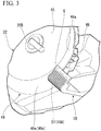
FIG. 3 is a perspective view of an end portion casing disposed on a motor side and a stabilizer. -
FIG. 4 is a sectional view of an end portion of the end portion casing and a cross flow fan inFIG. 2 taken along line C1-C2. -
FIG. 5 is a sectional view of the end portion of the end portion casing and the cross flow fan inFIG. 2 taken along line D1-D2. -
FIG. 6 is a sectional view of the end portion of the end portion casing and the cross flow fan inFIG. 2 taken along line E1-E2. -
FIG. 7 is a sectional view of the end portion of the end portion casing and the cross flow fan inFIG. 2 taken along line F1-F2. -
FIG. 8 is a sectional view of the end portion of the end portion casing and the cross flow fan inFIG. 2 taken along line G1-G2. -
FIG. 9 is a sectional view illustrating an end portion casing according to a modified example of the embodiment. - An air conditioning
indoor unit 10 according to an embodiment will be described with reference toFIGS. 1 to 8 . InFIG. 1 , "X" represents a width direction of ahousing 11 and "O" represents a central axis (hereinafter, referred to as "central axis O") of across flow fan 15. - In
FIGS. 1 and2 , a direction Z is a height direction (perpendicular direction) of thehousing 11 which is orthogonal to a direction X. InFIG. 2 , a direction Y is a depth direction of thehousing 11 which is orthogonal to the direction X and the direction Z shown inFIG. 1 . - In
FIGS. 4 to 7 , a section on astabilizer 18 side is illustrated to be positioned on a lower side in the drawings. InFIGS. 1 to 8 , the same components are given the same reference numerals. - The air conditioning
indoor unit 10 includes thehousing 11, aheat exchange unit 13, thecross flow fan 15, abearing portion 16, arear guider 17, thestabilizer 18, an airoutlet flow path 19, amotor 20,end portion casings wind directing plates 24. - The
housing 11 has a hollow portion inside thereof and thehousing 11 extends in the direction X. Thehousing 11 is provided with anair inlet port 11A and anair outlet port 11B. - The
air inlet port 11A is disposed close to an upper surface of the housing 11 (disposed on one side in direction Z). Theair inlet port 11A is used when air in an indoor place where the air conditioningindoor unit 10 is disposed is sucked into thehousing 11. - The
air outlet port 11B is disposed close to a lower surface of the housing 11 (disposed on other side in direction Z). Theair outlet port 11B is an opening portion that is used when air after heat exchange flowing out from thecross flow fan 15 is discharged to the indoor place. - The
heat exchange unit 13 is accommodated in thehousing 11 and a plurality of heat exchangers constitute theheat exchange unit 13. Theheat exchange unit 13 is provided at a position separated from thecross flow fan 15. - The
heat exchange unit 13 has a U-like shape. Theheat exchange unit 13 is disposed to surround a first outercircumferential surface 31b (outer circumferential surface corresponding toair inflow region 31A) of thecross flow fan 15. - The
heat exchange unit 13 performs heat exchange between indoor air sucked through theair inlet port 11A and a coolant flowing through a pipe of theheat exchange unit 13. - The
cross flow fan 15 is accommodated in thehousing 11. Thecross flow fan 15 includes a cross flow fanmain body 31, ashaft portion 32, and ashaft accommodation portion 34. - The cross flow fan
main body 31 has a columnar shape and is disposed to extend in the direction X. The cross flow fanmain body 31 is provided with theair inflow region 31A into which the air after the heat exchange flows, anair outflow region 31B from which the air after the heat exchange flows out, an outercircumferential surface 31a, andend portions 31C and 31D arranged in the direction X. - The
air inflow region 31A is a region facing theheat exchange unit 13. Theair outflow region 31B is a region exposed to the airoutlet flow path 19 defined by therear guider 17 and thestabilizer 18. - The outer
circumferential surface 31a includes the first outercircumferential surface 31b and a second outercircumferential surface 31c. The first outercircumferential surface 31b is an outer circumferential surface, which is a portion of the outercircumferential surface 31a that corresponds to theair inflow region 31A. The second outercircumferential surface 31c is an outer circumferential surface, which is a portion of the outercircumferential surface 31a that corresponds to theair outflow region 31B. - The
end portions 31C and 310 include the above-described first and second outercircumferential surfaces bearing portion 16 side. Theend portion 31D is an end portion disposed on themotor 20 side. - The
shaft portion 32 is provided to protrude in the direction X from an end surface (end surface disposed on bearingportion 16 side) positioned on one side in the direction X. - The
shaft accommodation portion 34 is a recess portion formed close to an end surface (end surface disposed onmotor 20 side) positioned on the other side in the direction X. Theshaft accommodation portion 34 is formed to extend in the direction X toward theshaft portion 32. - The bearing
portion 16 is accommodated in thehousing 11. The bearingportion 16 rotatably supports theshaft portion 32. - The
rear guider 17 is accommodated in thehousing 11. Therear guider 17 is disposed close to a rear surface of thehousing 11. Therear guider 17 has a curved shape that protrudes toward the rear surface of thehousing 11. Asurface 17a of therear guider 17 that is positioned on thestabilizer 18 side is a curved surface. - The
rear guider 17 is provided with afirst end portion 17A (lower end portion) positioned on theair outlet port 11B side and asecond end portion 17B positioned opposite to thefirst end portion 17A. - The
first end portion 17A is connected to a portion of thehousing 11 that is positioned close to the rear surface of thehousing 11, thehousing 11 defining theair outlet port 11B. - The
second end portion 17B is connected to portions of theend portion casings air inflow region 31A and the air outflow region 3 1B. - The
stabilizer 18 is accommodated in thehousing 11. Thestabilizer 18 is provided with atongue portion 37 constituting oneend portion 18A, theother end portion 18B, and asurface 18a. - The
tongue portion 37 is disposed in a state of inclined with respect to a portion of thestabilizer 18 other than thetongue portion 37 while being inclined toward theair inlet port 11A side. Thetongue portion 37 is connected to theend portion casings tongue portion 37 is connected to the end portion casing 22 will be described later. - The
tongue portion 37 has a function of suppressing generation of a wind noise (blade passing frequency noise) which is caused by interference between an air vortex and blades of thecross flow fan 15. - The
other end portion 18B is connected to a portion of thehousing 11 that is positioned close to a front surface of thehousing 11, thehousing 11 defining theair outlet port 11B. - The
surface 18a is a surface disposed on therear guider 17 side. Thesurface 18a is disposed to be separated from thesurface 17a in the direction Y. - The air
outlet flow path 19 is a flow path formed between thesurface 17a of therear guider 17 and thesurface 18a of thestabilizer 18. - Outer surfaces of the
end portion casings air outflow region 31B and the second outercircumferential surface 31c corresponding to theair outflow region 31B are exposed through the airoutlet flow path 19 and the airoutlet flow path 19 communicates with theair outlet port 11B. Accordingly, the air after the heat exchange flowing out from thecross flow fan 15 to the airoutlet flow path 19 is supplied to the indoor space via theair outlet port 11B. - The
motor 20 is accommodated in thehousing 11. Themotor 20 includes a motormain body 20A and amotor shaft 20B. The motormain body 20A is supported by a supporting member (not shown). - The
motor shaft 20B is connected to the motormain body 20A and extends in the direction X. Themotor shaft 20B is fixed to the cross flow fanmain body 31 in a state of being accommodated in theshaft accommodation portion 34. Themotor 20 is a drive unit for rotation of thecross flow fan 15. - The end portion casing 21 is accommodated in the
housing 11. The end portion casing 21 is supported by a supporting member (not shown). - The end portion casing 21 is provided with a
circular portion 41 and acylindrical portion 42. In the center of thecircular portion 41, anopening portion 41A through which theshaft portion 32 is inserted is formed. Thecircular portion 41 faces one end surface of the cross flow fanmain body 31 with a gap (gap having same size asfirst gap 48G which will be described later) interposed therebetween in the direction X. - One end of the
cylindrical portion 42 is connected to thecircular portion 41 and thecylindrical portion 42 extends in the direction X. Thecylindrical portion 42 faces the first and second outercircumferential surfaces main body 31. - The end portion casing 21 configured as described above is provided to surround an end surface and the first and second outer
circumferential surfaces - The end portion casing 22 is accommodated in the
housing 11. The end portion casing 22 is supported with respect to thehousing 11 by a supporting member (not shown). - The end portion casing 22 is provided with a
circular portion 45 and atubular portion 46. - In the center of the
circular portion 45, anopening portion 45A through which themotor shaft 20B is inserted is formed. Thecircular portion 45 faces the other end surface of the cross flow fanmain body 31 with a gap interposed therebetween in the direction X. - One end of the
tubular portion 46 is connected to thecircular portion 45. Thetubular portion 46 is provided with afirst portion 48 and asecond portion 49. - The
first portion 48 is provided to surround the first outercircumferential surface 31b corresponding to theair inflow region 31A. Thefirst portion 48 is provided with a firstinner surface 48a that faces the first outercircumferential surface 31b and forms thefirst gap 48G between the firstinner surface 48a and the first outercircumferential surface 31b. The size of thefirst gap 48G is constant in a circumferential direction of the cross flow fanmain body 31. - The
second portion 49 is provided to surround the second outercircumferential surface 31c corresponding to theair outflow region 31B. Anend portion 49A of thesecond portion 49 that is positioned opposite to an end portion on thecircular portion 45 side is inclined in a direction away from the central axis O of thecross flow fan 15. - The
second portion 49 is provided with a secondinner surface 49a disposed on the second outercircumferential surface 31c side. The secondinner surface 49a is an inclined surface inclined with respect to the central axis O of thecross flow fan 15. - The second
inner surface 49a is provided with a firstinclined surface 49b and a secondinclined surface 49c. - The first
inclined surface 49b is disposed on therear guider 17 side and is an inclined surface extending from thesecond end portion 17B of therear guider 17. The firstinclined surface 49b is an inclined surface of which the angle of inclination with respect to the central axis O gradually increases toward thefirst end portion 17A side from thesecond end portion 17B. - The second
inclined surface 49c is disposed on thestabilizer 18 side (first end portion 17A side) and is a surface integrated with the first inclined surface. No level difference is formed between the secondinclined surface 49c and the firstinclined surface 49b and the secondinclined surface 49c and the firstinclined surface 49b are connected to each other via a smooth surface. - The second
inclined surface 49c is inclined with respect to the central axis O. The secondinclined surface 49c is inclined at the same inclination angle as an inclination angle in a boundary between the firstinclined surface 49b and the secondinclined surface 49c. That is, the secondinclined surface 49c is an inclined surface of which the angle of inclination with respect to the central axis O is constant. - A
second gap 49G is formed between the secondinner surface 49a and the second outercircumferential surface 31c corresponding to theair outflow region 31B configured as described above. Thesecond gap 49G is a gap wider than thefirst gap 48G. - As described above, the
second gap 49G, which is formed between the second outercircumferential surface 31c of the cross flow fanmain body 31 corresponding to theair outflow region 31B and the secondinner surface 49a of thesecond portion 49 constituting the end portion casing 22 is made wider than thefirst gap 48G, which is formed between the first outercircumferential surface 31b of the cross flow fanmain body 31 corresponding to theair inflow region 31A and the firstinner surface 48a of thefirst portion 48 constituting theend portion casing 22. Therefore, it is possible to reduce a possibility that thesecond portion 49 inhibits a flow of air blown from the second outercircumferential surface 31c of theend portion 31D of the cross flow fanmain body 31. - Accordingly, it is possible to suppress indoor air entering the cross flow fan
main body 31 through the second outercircumferential surface 31c of theend portion 31D of the cross flow fanmain body 31 and thus it is possible to suppress generation of a blade passing frequency noise. - In addition, since the second
inner surface 49a is an inclined surface that is inclined in a direction away from the central axis O of thecross flow fan 15, thesecond gap 49G can be made wider than thefirst gap 48G and air blown from theend portion 31D of thecross flow fan 15 can be guided in a direction toward the center of thecross flow fan 15. - In addition, since the second
inner surface 49a which is an inclined surface includes the firstinclined surface 49b of which the angle of inclination with respect to the central axis O gradually increases toward thefirst end portion 17A side from thesecond end portion 17B and the secondinclined surface 49c which is integrated with the firstinclined surface 49b and of which the angle of inclination with respect to the central axis O is constant, air flowing out from the second outercircumferential surface 31c of theend portion 31D of the cross flow fanmain body 31 can be smoothly guided in a direction toward theair outlet port 11B. - A level difference G is formed between an end portion of the second
inclined surface 49c that is positioned on thestabilizer 18 side and the firstinner surface 48a since the secondinclined surface 49c is inclined with respect to the central axis O (refer toFIG. 3 ). - A portion of the
tongue portion 37 of thestabilizer 18 that has a shape capable of lessening the influence of the level difference G is disposed to extend at the level difference G. - As described above, since the portion of the
tongue portion 37 that has the shape capable of alleviating of the level difference G is disposed at the level difference G, the level difference G formed in a boundary between the secondinclined surface 49c and the firstinner surface 48a can be decreased. Accordingly, it is possible to suppress turbulence which occurs when air flowing out from thecross flow fan 15 collides with the level difference G. - The upper and lower
wind directing plates 24 are provided in thehousing 11 corresponding to theair outlet port 11B. The upper and lowerwind directing plates 24 adjust a direction in which air flowing out from thecross flow fan 15 is blown. - According to the air conditioning
indoor unit 10 in the present embodiment, thesecond gap 49G, which is formed between the second outercircumferential surface 31c of the cross flow fanmain body 31 corresponding to theair outflow region 31B and the secondinner surface 49a of thesecond portion 49 constituting the end portion casing 22 is made wider than thefirst gap 48G, which is formed between the first outercircumferential surface 31b of the cross flow fanmain body 31 corresponding to theair inflow region 31A and the firstinner surface 48a of thefirst portion 48 constituting theend portion casing 22. Therefore, it is possible to reduce a possibility that thesecond portion 49 inhibits a flow of air blown from the second outercircumferential surface 31c of theend portion 31D of the cross flow fanmain body 31. - Accordingly, it is possible to suppress indoor air entering the cross flow fan
main body 31 through the second outercircumferential surface 31c of theend portion 31D of the cross flow fanmain body 31 and thus it is possible to suppress generation of a blade passing frequency noise. - Note that, in the present embodiment, a case where the end portion casing 22 disposed on the
motor 20 side is provided with the first andsecond portions portion 16 side is provided with the first andsecond portions end portion casings second portions - Next, an end portion casing 55 according to a modified example of the present embodiment will be described with reference to
FIG. 9 . InFIG. 9 , the same components as those in the structure shown inFIGS. 4 to 7 are given the same reference numerals. - As shown in
FIG. 9 , the end portion casing 55 has the same configuration as the end portion casing 22 except that asecond portion 56 is provided instead of thesecond portion 49 constituting the end portion casing 22 described above and a portion of thecircular portion 45 that is positioned on the second outercircumferential surface 31c side is extended. - A second
inner surface 56a of thesecond portion 56 is a surface not inclined with respect to the central axis O. Asecond gap 56G of which the width is greater than that of thefirst gap 48G is formed between the secondinner surface 56a and the second outercircumferential surface 31c. - The size of the
second gap 56G is constant in the circumferential direction of the second outercircumferential surface 31c. - In a case where the end portion casing 55 configured as described is used as well, it is possible to suppress indoor air entering the cross flow fan
main body 31 through the second outercircumferential surface 31c of the end portion of the cross flow fanmain body 31 and thus it is possible to suppress generation of a blade passing frequency noise. - While preferred embodiments of the invention have been described and illustrated above, it should be understood that these are exemplary of the invention and are not to be considered as limiting. Additions, omissions, substitutions, and other modifications can be made without departing from the spirit or scope of the present invention. Accordingly, the invention is not to be considered as being limited by the foregoing description, and is only limited by the scope of the appended claims.
- For example, the second
inner surface 49a may be configured of the firstinclined surface 49b only.
Claims (4)
- An air conditioning indoor unit comprising:a housing that is provided with an air inlet port through which indoor air is sucked and an air outlet port through which the air is blown outward;a heat exchange unit that is accommodated in the housing and performs heat exchange with the air sucked through the air inlet port;a cross flow fan that is accommodated in the housing, is disposed to extend in a width direction of the housing, and is provided with an outer circumferential surface, the outer circumferential surface including a first outer circumferential surface corresponding to an air inflow region into which the air after the heat exchange flows and a second outer circumferential surface corresponding to an air outflow region from which the air after the heat exchange flows out;a rear guider that is accommodated in the housing and is disposed close to a rear surface of the housing;a stabilizer that is accommodated in the housing, is disposed close to a front surface of the rear guider, and defines an air outlet flow path that communicates with the air outlet port and through which the air outflow region is exposed, the air outlet flow path being defined between the stabilizer and the rear guider; andan end portion casing that is provided for an end portion of the cross flow fan and is provided with a first portion and a second portion, the first portion being provided with a first inner surface forming a first gap between the first inner surface and the first outer circumferential surface positioned at the end portion of the cross flow fan and the second portion being provided with a second inner surface forming a second gap between the second inner surface and the second outer circumferential surface positioned at the end portion of the cross flow fan,wherein the second gap is wider than the first gap.
- The air conditioning indoor unit according to claim 1,
wherein the second inner surface is an inclined surface that is inclined in a direction away from a central axis of the cross flow fan. - The air conditioning indoor unit according to claim 2,wherein the rear guider is provided with a first end portion positioned on the air outlet port side and a second end portion positioned opposite to the first end portion,wherein the second end portion is connected to a portion of the end portion casing that corresponds to a boundary between the air inflow region and the air outflow region, andwherein the inclined surface includes a first inclined surface that is disposed on the second end portion side and of which an angle of inclination with respect to the central axis gradually increases toward the first end portion from the second end portion and a second inclined surface that is disposed on the first end portion side, that is integrated with the first inclined surface, and of which an angle of inclination with respect to the central axis is constant.
- The air conditioning indoor unit according to claim 3,wherein a level difference is formed in a boundary between the second inclined surface and the first inner surface,wherein an end portion of the stabilizer that is positioned opposite to an end portion positioned on the air outlet port side is provided with a tongue portion,wherein the tongue portion has a shape alleviating the level difference, andwherein a portion of the tongue portion is disposed to extend at the level difference.
Applications Claiming Priority (1)
| Application Number | Priority Date | Filing Date | Title |
|---|---|---|---|
| JP2018120744A JP7191554B2 (en) | 2018-06-26 | 2018-06-26 | Air conditioning indoor unit |
Publications (2)
| Publication Number | Publication Date |
|---|---|
| EP3587937A1 true EP3587937A1 (en) | 2020-01-01 |
| EP3587937B1 EP3587937B1 (en) | 2022-07-27 |
Family
ID=67070642
Family Applications (1)
| Application Number | Title | Priority Date | Filing Date |
|---|---|---|---|
| EP19182316.0A Active EP3587937B1 (en) | 2018-06-26 | 2019-06-25 | Air conditioning indoor unit |
Country Status (4)
| Country | Link |
|---|---|
| EP (1) | EP3587937B1 (en) |
| JP (1) | JP7191554B2 (en) |
| AU (1) | AU2019204463B2 (en) |
| ES (1) | ES2927309T3 (en) |
Citations (6)
| Publication number | Priority date | Publication date | Assignee | Title |
|---|---|---|---|---|
| JPH08319990A (en) * | 1995-05-26 | 1996-12-03 | Toshiba Corp | Blower |
| JP3171487B2 (en) * | 1992-08-28 | 2001-05-28 | 東芝キヤリア株式会社 | Air conditioner |
| EP2719957A1 (en) * | 2011-06-10 | 2014-04-16 | Mitsubishi Electric Corporation | Air conditioner |
| JP2015190637A (en) | 2014-03-27 | 2015-11-02 | 株式会社富士通ゼネラル | Air conditioner |
| JP2016102622A (en) * | 2014-11-28 | 2016-06-02 | シャープ株式会社 | Air conditioner |
| JP2017020713A (en) * | 2015-07-10 | 2017-01-26 | シャープ株式会社 | Air conditioner |
Family Cites Families (6)
| Publication number | Priority date | Publication date | Assignee | Title |
|---|---|---|---|---|
| JPS5839413U (en) * | 1981-09-09 | 1983-03-15 | 株式会社東芝 | Air conditioner fan casing |
| GB2302937B (en) * | 1995-07-05 | 1998-11-25 | Toshiba Kk | Indoor unit for air conditioner |
| JP5744209B2 (en) | 2011-08-31 | 2015-07-08 | 三菱電機株式会社 | Air conditioner |
| JP5949750B2 (en) * | 2013-12-25 | 2016-07-13 | ダイキン工業株式会社 | Cross flow fan |
| WO2018042689A1 (en) | 2016-08-29 | 2018-03-08 | シャープ株式会社 | Air conditioner |
| CN108019917B (en) * | 2016-11-01 | 2020-09-25 | 青岛海尔空调器有限总公司 | Air conditioner indoor unit |
-
2018
- 2018-06-26 JP JP2018120744A patent/JP7191554B2/en active Active
-
2019
- 2019-06-25 EP EP19182316.0A patent/EP3587937B1/en active Active
- 2019-06-25 AU AU2019204463A patent/AU2019204463B2/en active Active
- 2019-06-25 ES ES19182316T patent/ES2927309T3/en active Active
Patent Citations (6)
| Publication number | Priority date | Publication date | Assignee | Title |
|---|---|---|---|---|
| JP3171487B2 (en) * | 1992-08-28 | 2001-05-28 | 東芝キヤリア株式会社 | Air conditioner |
| JPH08319990A (en) * | 1995-05-26 | 1996-12-03 | Toshiba Corp | Blower |
| EP2719957A1 (en) * | 2011-06-10 | 2014-04-16 | Mitsubishi Electric Corporation | Air conditioner |
| JP2015190637A (en) | 2014-03-27 | 2015-11-02 | 株式会社富士通ゼネラル | Air conditioner |
| JP2016102622A (en) * | 2014-11-28 | 2016-06-02 | シャープ株式会社 | Air conditioner |
| JP2017020713A (en) * | 2015-07-10 | 2017-01-26 | シャープ株式会社 | Air conditioner |
Also Published As
| Publication number | Publication date |
|---|---|
| AU2019204463B2 (en) | 2020-06-04 |
| JP7191554B2 (en) | 2022-12-19 |
| JP2020003103A (en) | 2020-01-09 |
| ES2927309T3 (en) | 2022-11-04 |
| EP3587937B1 (en) | 2022-07-27 |
| AU2019204463A1 (en) | 2020-01-23 |
Similar Documents
| Publication | Publication Date | Title |
|---|---|---|
| JP4823294B2 (en) | Blower and heat pump device using this blower | |
| JP3516909B2 (en) | Centrifugal blower | |
| WO2016170831A1 (en) | Centrifugal blower | |
| JP2007120880A (en) | Cross flow fan | |
| CN110506164B (en) | Propeller fans and outdoor units for air conditioners | |
| JP2010236437A (en) | Cross flow fan and air conditioner equipped with the cross flow fan | |
| JP6330738B2 (en) | Centrifugal blower and air conditioner using the same | |
| JP5338842B2 (en) | Cross flow fan | |
| EP3587937B1 (en) | Air conditioning indoor unit | |
| KR101233538B1 (en) | Cross-flow fan and air conditioner equipped with same | |
| JP6844526B2 (en) | Multi-wing centrifugal fan | |
| JPH0642498A (en) | Axial flow blower | |
| WO2020110967A1 (en) | Propeller fan | |
| CN112050296B (en) | Air conditioner | |
| CN108661950B (en) | Volute, fan and refrigeration equipment | |
| JP6487179B2 (en) | Blower | |
| JP7120360B1 (en) | Blower and indoor unit | |
| WO2020110968A1 (en) | Propeller fan | |
| WO2020110969A1 (en) | Propeller fan | |
| JP2015214912A (en) | Axial flow fan and air conditioner equipped with the same | |
| CN116964330A (en) | Fans and indoor units | |
| JP2002046449A (en) | Air conditioner for vehicle | |
| JPWO2014167707A1 (en) | Centrifugal blower | |
| TW202317922A (en) | Outdoor machine of refrigeration cycle apparatus | |
| WO2020110970A1 (en) | Propeller fan |
Legal Events
| Date | Code | Title | Description |
|---|---|---|---|
| PUAI | Public reference made under article 153(3) epc to a published international application that has entered the european phase |
Free format text: ORIGINAL CODE: 0009012 |
|
| STAA | Information on the status of an ep patent application or granted ep patent |
Free format text: STATUS: THE APPLICATION HAS BEEN PUBLISHED |
|
| AK | Designated contracting states |
Kind code of ref document: A1 Designated state(s): AL AT BE BG CH CY CZ DE DK EE ES FI FR GB GR HR HU IE IS IT LI LT LU LV MC MK MT NL NO PL PT RO RS SE SI SK SM TR |
|
| AX | Request for extension of the european patent |
Extension state: BA ME |
|
| STAA | Information on the status of an ep patent application or granted ep patent |
Free format text: STATUS: REQUEST FOR EXAMINATION WAS MADE |
|
| 17P | Request for examination filed |
Effective date: 20200701 |
|
| RBV | Designated contracting states (corrected) |
Designated state(s): AL AT BE BG CH CY CZ DE DK EE ES FI FR GB GR HR HU IE IS IT LI LT LU LV MC MK MT NL NO PL PT RO RS SE SI SK SM TR |
|
| GRAP | Despatch of communication of intention to grant a patent |
Free format text: ORIGINAL CODE: EPIDOSNIGR1 |
|
| STAA | Information on the status of an ep patent application or granted ep patent |
Free format text: STATUS: GRANT OF PATENT IS INTENDED |
|
| RIC1 | Information provided on ipc code assigned before grant |
Ipc: F04D 29/42 20060101ALI20220128BHEP Ipc: F04D 17/04 20060101ALI20220128BHEP Ipc: F24F 1/0011 20190101ALI20220128BHEP Ipc: F24F 13/24 20060101ALI20220128BHEP Ipc: F24F 13/08 20060101ALI20220128BHEP Ipc: F24F 1/0025 20190101AFI20220128BHEP |
|
| INTG | Intention to grant announced |
Effective date: 20220215 |
|
| GRAS | Grant fee paid |
Free format text: ORIGINAL CODE: EPIDOSNIGR3 |
|
| GRAA | (expected) grant |
Free format text: ORIGINAL CODE: 0009210 |
|
| STAA | Information on the status of an ep patent application or granted ep patent |
Free format text: STATUS: THE PATENT HAS BEEN GRANTED |
|
| AK | Designated contracting states |
Kind code of ref document: B1 Designated state(s): AL AT BE BG CH CY CZ DE DK EE ES FI FR GB GR HR HU IE IS IT LI LT LU LV MC MK MT NL NO PL PT RO RS SE SI SK SM TR |
|
| REG | Reference to a national code |
Ref country code: CH Ref legal event code: EP |
|
| REG | Reference to a national code |
Ref country code: AT Ref legal event code: REF Ref document number: 1507294 Country of ref document: AT Kind code of ref document: T Effective date: 20220815 |
|
| REG | Reference to a national code |
Ref country code: DE Ref legal event code: R096 Ref document number: 602019017388 Country of ref document: DE |
|
| REG | Reference to a national code |
Ref country code: IE Ref legal event code: FG4D |
|
| REG | Reference to a national code |
Ref country code: ES Ref legal event code: FG2A Ref document number: 2927309 Country of ref document: ES Kind code of ref document: T3 Effective date: 20221104 |
|
| REG | Reference to a national code |
Ref country code: LT Ref legal event code: MG9D |
|
| REG | Reference to a national code |
Ref country code: NL Ref legal event code: MP Effective date: 20220727 |
|
| PG25 | Lapsed in a contracting state [announced via postgrant information from national office to epo] |
Ref country code: SE Free format text: LAPSE BECAUSE OF FAILURE TO SUBMIT A TRANSLATION OF THE DESCRIPTION OR TO PAY THE FEE WITHIN THE PRESCRIBED TIME-LIMIT Effective date: 20220727 Ref country code: RS Free format text: LAPSE BECAUSE OF FAILURE TO SUBMIT A TRANSLATION OF THE DESCRIPTION OR TO PAY THE FEE WITHIN THE PRESCRIBED TIME-LIMIT Effective date: 20220727 Ref country code: PT Free format text: LAPSE BECAUSE OF FAILURE TO SUBMIT A TRANSLATION OF THE DESCRIPTION OR TO PAY THE FEE WITHIN THE PRESCRIBED TIME-LIMIT Effective date: 20221128 Ref country code: NO Free format text: LAPSE BECAUSE OF FAILURE TO SUBMIT A TRANSLATION OF THE DESCRIPTION OR TO PAY THE FEE WITHIN THE PRESCRIBED TIME-LIMIT Effective date: 20221027 Ref country code: NL Free format text: LAPSE BECAUSE OF FAILURE TO SUBMIT A TRANSLATION OF THE DESCRIPTION OR TO PAY THE FEE WITHIN THE PRESCRIBED TIME-LIMIT Effective date: 20220727 Ref country code: LV Free format text: LAPSE BECAUSE OF FAILURE TO SUBMIT A TRANSLATION OF THE DESCRIPTION OR TO PAY THE FEE WITHIN THE PRESCRIBED TIME-LIMIT Effective date: 20220727 Ref country code: LT Free format text: LAPSE BECAUSE OF FAILURE TO SUBMIT A TRANSLATION OF THE DESCRIPTION OR TO PAY THE FEE WITHIN THE PRESCRIBED TIME-LIMIT Effective date: 20220727 Ref country code: FI Free format text: LAPSE BECAUSE OF FAILURE TO SUBMIT A TRANSLATION OF THE DESCRIPTION OR TO PAY THE FEE WITHIN THE PRESCRIBED TIME-LIMIT Effective date: 20220727 |
|
| REG | Reference to a national code |
Ref country code: AT Ref legal event code: MK05 Ref document number: 1507294 Country of ref document: AT Kind code of ref document: T Effective date: 20220727 |
|
| PG25 | Lapsed in a contracting state [announced via postgrant information from national office to epo] |
Ref country code: PL Free format text: LAPSE BECAUSE OF FAILURE TO SUBMIT A TRANSLATION OF THE DESCRIPTION OR TO PAY THE FEE WITHIN THE PRESCRIBED TIME-LIMIT Effective date: 20220727 Ref country code: IS Free format text: LAPSE BECAUSE OF FAILURE TO SUBMIT A TRANSLATION OF THE DESCRIPTION OR TO PAY THE FEE WITHIN THE PRESCRIBED TIME-LIMIT Effective date: 20221127 Ref country code: HR Free format text: LAPSE BECAUSE OF FAILURE TO SUBMIT A TRANSLATION OF THE DESCRIPTION OR TO PAY THE FEE WITHIN THE PRESCRIBED TIME-LIMIT Effective date: 20220727 Ref country code: GR Free format text: LAPSE BECAUSE OF FAILURE TO SUBMIT A TRANSLATION OF THE DESCRIPTION OR TO PAY THE FEE WITHIN THE PRESCRIBED TIME-LIMIT Effective date: 20221028 |
|
| PG25 | Lapsed in a contracting state [announced via postgrant information from national office to epo] |
Ref country code: SM Free format text: LAPSE BECAUSE OF FAILURE TO SUBMIT A TRANSLATION OF THE DESCRIPTION OR TO PAY THE FEE WITHIN THE PRESCRIBED TIME-LIMIT Effective date: 20220727 Ref country code: RO Free format text: LAPSE BECAUSE OF FAILURE TO SUBMIT A TRANSLATION OF THE DESCRIPTION OR TO PAY THE FEE WITHIN THE PRESCRIBED TIME-LIMIT Effective date: 20220727 Ref country code: DK Free format text: LAPSE BECAUSE OF FAILURE TO SUBMIT A TRANSLATION OF THE DESCRIPTION OR TO PAY THE FEE WITHIN THE PRESCRIBED TIME-LIMIT Effective date: 20220727 Ref country code: CZ Free format text: LAPSE BECAUSE OF FAILURE TO SUBMIT A TRANSLATION OF THE DESCRIPTION OR TO PAY THE FEE WITHIN THE PRESCRIBED TIME-LIMIT Effective date: 20220727 Ref country code: AT Free format text: LAPSE BECAUSE OF FAILURE TO SUBMIT A TRANSLATION OF THE DESCRIPTION OR TO PAY THE FEE WITHIN THE PRESCRIBED TIME-LIMIT Effective date: 20220727 |
|
| REG | Reference to a national code |
Ref country code: DE Ref legal event code: R097 Ref document number: 602019017388 Country of ref document: DE |
|
| PG25 | Lapsed in a contracting state [announced via postgrant information from national office to epo] |
Ref country code: SK Free format text: LAPSE BECAUSE OF FAILURE TO SUBMIT A TRANSLATION OF THE DESCRIPTION OR TO PAY THE FEE WITHIN THE PRESCRIBED TIME-LIMIT Effective date: 20220727 Ref country code: EE Free format text: LAPSE BECAUSE OF FAILURE TO SUBMIT A TRANSLATION OF THE DESCRIPTION OR TO PAY THE FEE WITHIN THE PRESCRIBED TIME-LIMIT Effective date: 20220727 |
|
| PLBE | No opposition filed within time limit |
Free format text: ORIGINAL CODE: 0009261 |
|
| STAA | Information on the status of an ep patent application or granted ep patent |
Free format text: STATUS: NO OPPOSITION FILED WITHIN TIME LIMIT |
|
| PG25 | Lapsed in a contracting state [announced via postgrant information from national office to epo] |
Ref country code: AL Free format text: LAPSE BECAUSE OF FAILURE TO SUBMIT A TRANSLATION OF THE DESCRIPTION OR TO PAY THE FEE WITHIN THE PRESCRIBED TIME-LIMIT Effective date: 20220727 |
|
| 26N | No opposition filed |
Effective date: 20230502 |
|
| PG25 | Lapsed in a contracting state [announced via postgrant information from national office to epo] |
Ref country code: SI Free format text: LAPSE BECAUSE OF FAILURE TO SUBMIT A TRANSLATION OF THE DESCRIPTION OR TO PAY THE FEE WITHIN THE PRESCRIBED TIME-LIMIT Effective date: 20220727 |
|
| PG25 | Lapsed in a contracting state [announced via postgrant information from national office to epo] |
Ref country code: MC Free format text: LAPSE BECAUSE OF FAILURE TO SUBMIT A TRANSLATION OF THE DESCRIPTION OR TO PAY THE FEE WITHIN THE PRESCRIBED TIME-LIMIT Effective date: 20220727 |
|
| PG25 | Lapsed in a contracting state [announced via postgrant information from national office to epo] |
Ref country code: MC Free format text: LAPSE BECAUSE OF FAILURE TO SUBMIT A TRANSLATION OF THE DESCRIPTION OR TO PAY THE FEE WITHIN THE PRESCRIBED TIME-LIMIT Effective date: 20220727 |
|
| REG | Reference to a national code |
Ref country code: CH Ref legal event code: PL |
|
| REG | Reference to a national code |
Ref country code: BE Ref legal event code: MM Effective date: 20230630 |
|
| GBPC | Gb: european patent ceased through non-payment of renewal fee |
Effective date: 20230625 |
|
| PG25 | Lapsed in a contracting state [announced via postgrant information from national office to epo] |
Ref country code: LU Free format text: LAPSE BECAUSE OF NON-PAYMENT OF DUE FEES Effective date: 20230625 |
|
| REG | Reference to a national code |
Ref country code: IE Ref legal event code: MM4A |
|
| PG25 | Lapsed in a contracting state [announced via postgrant information from national office to epo] |
Ref country code: LU Free format text: LAPSE BECAUSE OF NON-PAYMENT OF DUE FEES Effective date: 20230625 |
|
| PG25 | Lapsed in a contracting state [announced via postgrant information from national office to epo] |
Ref country code: IE Free format text: LAPSE BECAUSE OF NON-PAYMENT OF DUE FEES Effective date: 20230625 |
|
| PG25 | Lapsed in a contracting state [announced via postgrant information from national office to epo] |
Ref country code: IE Free format text: LAPSE BECAUSE OF NON-PAYMENT OF DUE FEES Effective date: 20230625 Ref country code: CH Free format text: LAPSE BECAUSE OF NON-PAYMENT OF DUE FEES Effective date: 20230630 Ref country code: GB Free format text: LAPSE BECAUSE OF NON-PAYMENT OF DUE FEES Effective date: 20230625 |
|
| PG25 | Lapsed in a contracting state [announced via postgrant information from national office to epo] |
Ref country code: FR Free format text: LAPSE BECAUSE OF NON-PAYMENT OF DUE FEES Effective date: 20230630 Ref country code: BE Free format text: LAPSE BECAUSE OF NON-PAYMENT OF DUE FEES Effective date: 20230630 |
|
| PG25 | Lapsed in a contracting state [announced via postgrant information from national office to epo] |
Ref country code: BG Free format text: LAPSE BECAUSE OF FAILURE TO SUBMIT A TRANSLATION OF THE DESCRIPTION OR TO PAY THE FEE WITHIN THE PRESCRIBED TIME-LIMIT Effective date: 20220727 |
|
| PG25 | Lapsed in a contracting state [announced via postgrant information from national office to epo] |
Ref country code: BG Free format text: LAPSE BECAUSE OF FAILURE TO SUBMIT A TRANSLATION OF THE DESCRIPTION OR TO PAY THE FEE WITHIN THE PRESCRIBED TIME-LIMIT Effective date: 20220727 |
|
| PGFP | Annual fee paid to national office [announced via postgrant information from national office to epo] |
Ref country code: DE Payment date: 20250429 Year of fee payment: 7 |
|
| PGFP | Annual fee paid to national office [announced via postgrant information from national office to epo] |
Ref country code: IT Payment date: 20250522 Year of fee payment: 7 |
|
| PG25 | Lapsed in a contracting state [announced via postgrant information from national office to epo] |
Ref country code: CY Free format text: LAPSE BECAUSE OF FAILURE TO SUBMIT A TRANSLATION OF THE DESCRIPTION OR TO PAY THE FEE WITHIN THE PRESCRIBED TIME-LIMIT; INVALID AB INITIO Effective date: 20190625 |
|
| PG25 | Lapsed in a contracting state [announced via postgrant information from national office to epo] |
Ref country code: HU Free format text: LAPSE BECAUSE OF FAILURE TO SUBMIT A TRANSLATION OF THE DESCRIPTION OR TO PAY THE FEE WITHIN THE PRESCRIBED TIME-LIMIT; INVALID AB INITIO Effective date: 20190625 |
|
| PGFP | Annual fee paid to national office [announced via postgrant information from national office to epo] |
Ref country code: ES Payment date: 20250701 Year of fee payment: 7 |
|
| PG25 | Lapsed in a contracting state [announced via postgrant information from national office to epo] |
Ref country code: TR Free format text: LAPSE BECAUSE OF FAILURE TO SUBMIT A TRANSLATION OF THE DESCRIPTION OR TO PAY THE FEE WITHIN THE PRESCRIBED TIME-LIMIT Effective date: 20220727 |