EP3587909A1 - Vehicular lamp fitting - Google Patents
Vehicular lamp fitting Download PDFInfo
- Publication number
- EP3587909A1 EP3587909A1 EP19181380.7A EP19181380A EP3587909A1 EP 3587909 A1 EP3587909 A1 EP 3587909A1 EP 19181380 A EP19181380 A EP 19181380A EP 3587909 A1 EP3587909 A1 EP 3587909A1
- Authority
- EP
- European Patent Office
- Prior art keywords
- light
- light control
- control surface
- guiding plate
- exits
- Prior art date
- Legal status (The legal status is an assumption and is not a legal conclusion. Google has not performed a legal analysis and makes no representation as to the accuracy of the status listed.)
- Granted
Links
Images




Classifications
-
- F—MECHANICAL ENGINEERING; LIGHTING; HEATING; WEAPONS; BLASTING
- F21—LIGHTING
- F21S—NON-PORTABLE LIGHTING DEVICES; SYSTEMS THEREOF; VEHICLE LIGHTING DEVICES SPECIALLY ADAPTED FOR VEHICLE EXTERIORS
- F21S43/00—Signalling devices specially adapted for vehicle exteriors, e.g. brake lamps, direction indicator lights or reversing lights
- F21S43/20—Signalling devices specially adapted for vehicle exteriors, e.g. brake lamps, direction indicator lights or reversing lights characterised by refractors, transparent cover plates, light guides or filters
- F21S43/235—Light guides
- F21S43/252—Two or more successive light guides
-
- F—MECHANICAL ENGINEERING; LIGHTING; HEATING; WEAPONS; BLASTING
- F21—LIGHTING
- F21S—NON-PORTABLE LIGHTING DEVICES; SYSTEMS THEREOF; VEHICLE LIGHTING DEVICES SPECIALLY ADAPTED FOR VEHICLE EXTERIORS
- F21S43/00—Signalling devices specially adapted for vehicle exteriors, e.g. brake lamps, direction indicator lights or reversing lights
- F21S43/20—Signalling devices specially adapted for vehicle exteriors, e.g. brake lamps, direction indicator lights or reversing lights characterised by refractors, transparent cover plates, light guides or filters
- F21S43/235—Light guides
- F21S43/236—Light guides characterised by the shape of the light guide
- F21S43/239—Light guides characterised by the shape of the light guide plate-shaped
-
- F—MECHANICAL ENGINEERING; LIGHTING; HEATING; WEAPONS; BLASTING
- F21—LIGHTING
- F21S—NON-PORTABLE LIGHTING DEVICES; SYSTEMS THEREOF; VEHICLE LIGHTING DEVICES SPECIALLY ADAPTED FOR VEHICLE EXTERIORS
- F21S43/00—Signalling devices specially adapted for vehicle exteriors, e.g. brake lamps, direction indicator lights or reversing lights
- F21S43/10—Signalling devices specially adapted for vehicle exteriors, e.g. brake lamps, direction indicator lights or reversing lights characterised by the light source
- F21S43/13—Signalling devices specially adapted for vehicle exteriors, e.g. brake lamps, direction indicator lights or reversing lights characterised by the light source characterised by the type of light source
- F21S43/14—Light emitting diodes [LED]
-
- F—MECHANICAL ENGINEERING; LIGHTING; HEATING; WEAPONS; BLASTING
- F21—LIGHTING
- F21S—NON-PORTABLE LIGHTING DEVICES; SYSTEMS THEREOF; VEHICLE LIGHTING DEVICES SPECIALLY ADAPTED FOR VEHICLE EXTERIORS
- F21S43/00—Signalling devices specially adapted for vehicle exteriors, e.g. brake lamps, direction indicator lights or reversing lights
- F21S43/20—Signalling devices specially adapted for vehicle exteriors, e.g. brake lamps, direction indicator lights or reversing lights characterised by refractors, transparent cover plates, light guides or filters
- F21S43/235—Light guides
- F21S43/242—Light guides characterised by the emission area
- F21S43/245—Light guides characterised by the emission area emitting light from one or more of its major surfaces
-
- F—MECHANICAL ENGINEERING; LIGHTING; HEATING; WEAPONS; BLASTING
- F21—LIGHTING
- F21S—NON-PORTABLE LIGHTING DEVICES; SYSTEMS THEREOF; VEHICLE LIGHTING DEVICES SPECIALLY ADAPTED FOR VEHICLE EXTERIORS
- F21S43/00—Signalling devices specially adapted for vehicle exteriors, e.g. brake lamps, direction indicator lights or reversing lights
- F21S43/20—Signalling devices specially adapted for vehicle exteriors, e.g. brake lamps, direction indicator lights or reversing lights characterised by refractors, transparent cover plates, light guides or filters
- F21S43/235—Light guides
- F21S43/242—Light guides characterised by the emission area
- F21S43/246—Light guides characterised by the emission area having two or more output branches
-
- F—MECHANICAL ENGINEERING; LIGHTING; HEATING; WEAPONS; BLASTING
- F21—LIGHTING
- F21S—NON-PORTABLE LIGHTING DEVICES; SYSTEMS THEREOF; VEHICLE LIGHTING DEVICES SPECIALLY ADAPTED FOR VEHICLE EXTERIORS
- F21S43/00—Signalling devices specially adapted for vehicle exteriors, e.g. brake lamps, direction indicator lights or reversing lights
- F21S43/20—Signalling devices specially adapted for vehicle exteriors, e.g. brake lamps, direction indicator lights or reversing lights characterised by refractors, transparent cover plates, light guides or filters
- F21S43/235—Light guides
- F21S43/249—Light guides with two or more light sources being coupled into the light guide
-
- F—MECHANICAL ENGINEERING; LIGHTING; HEATING; WEAPONS; BLASTING
- F21—LIGHTING
- F21S—NON-PORTABLE LIGHTING DEVICES; SYSTEMS THEREOF; VEHICLE LIGHTING DEVICES SPECIALLY ADAPTED FOR VEHICLE EXTERIORS
- F21S43/00—Signalling devices specially adapted for vehicle exteriors, e.g. brake lamps, direction indicator lights or reversing lights
- F21S43/20—Signalling devices specially adapted for vehicle exteriors, e.g. brake lamps, direction indicator lights or reversing lights characterised by refractors, transparent cover plates, light guides or filters
- F21S43/235—Light guides
- F21S43/249—Light guides with two or more light sources being coupled into the light guide
- F21S43/2492—Light guides with two or more light sources being coupled into the light guide having two or more input branches
-
- G—PHYSICS
- G02—OPTICS
- G02B—OPTICAL ELEMENTS, SYSTEMS OR APPARATUS
- G02B6/00—Light guides; Structural details of arrangements comprising light guides and other optical elements, e.g. couplings
- G02B6/0001—Light guides; Structural details of arrangements comprising light guides and other optical elements, e.g. couplings specially adapted for lighting devices or systems
- G02B6/0011—Light guides; Structural details of arrangements comprising light guides and other optical elements, e.g. couplings specially adapted for lighting devices or systems the light guides being planar or of plate-like form
- G02B6/0013—Means for improving the coupling-in of light from the light source into the light guide
- G02B6/0015—Means for improving the coupling-in of light from the light source into the light guide provided on the surface of the light guide or in the bulk of it
- G02B6/0018—Redirecting means on the surface of the light guide
-
- G—PHYSICS
- G02—OPTICS
- G02B—OPTICAL ELEMENTS, SYSTEMS OR APPARATUS
- G02B6/00—Light guides; Structural details of arrangements comprising light guides and other optical elements, e.g. couplings
- G02B6/0001—Light guides; Structural details of arrangements comprising light guides and other optical elements, e.g. couplings specially adapted for lighting devices or systems
- G02B6/0011—Light guides; Structural details of arrangements comprising light guides and other optical elements, e.g. couplings specially adapted for lighting devices or systems the light guides being planar or of plate-like form
- G02B6/0033—Means for improving the coupling-out of light from the light guide
- G02B6/0035—Means for improving the coupling-out of light from the light guide provided on the surface of the light guide or in the bulk of it
- G02B6/0036—2-D arrangement of prisms, protrusions, indentations or roughened surfaces
-
- G—PHYSICS
- G02—OPTICS
- G02B—OPTICAL ELEMENTS, SYSTEMS OR APPARATUS
- G02B6/00—Light guides; Structural details of arrangements comprising light guides and other optical elements, e.g. couplings
- G02B6/0001—Light guides; Structural details of arrangements comprising light guides and other optical elements, e.g. couplings specially adapted for lighting devices or systems
- G02B6/0011—Light guides; Structural details of arrangements comprising light guides and other optical elements, e.g. couplings specially adapted for lighting devices or systems the light guides being planar or of plate-like form
- G02B6/0033—Means for improving the coupling-out of light from the light guide
- G02B6/0035—Means for improving the coupling-out of light from the light guide provided on the surface of the light guide or in the bulk of it
- G02B6/0038—Linear indentations or grooves, e.g. arc-shaped grooves or meandering grooves, extending over the full length or width of the light guide
Definitions
- the present invention relates to a vehicular lamp fitting, and more particularly to a vehicular lamp fitting that can control not only an exit angle of the light in the vertical direction, but also an exit angle of the light in the horizontal direction from a light source which emits light through the surface of a light guiding plate.
- a vehicular lamp fitting that includes: a light guiding plate having a front surface and a back surface on the opposite side of the front surface; and a light source which emits light guided by the light guiding plate, is known (e.g. Japanese Laid-open Patent Publication No. 2018-006226 ).
- the present invention has been made in view of the above circumstances and has an object of providing a vehicular lamp fitting that can control not only an exit angle of the light in the vertical direction, but also an exit angle of the light in the horizontal direction from a light source which emits light through the surface of a light guiding plate.
- an aspect of the present invention provides a vehicular lamp fitting, comprising: a light guiding plate having a front surface and a back surface disposed on the opposite side of the front surface; and a light source which emits light guided by the light guiding plate, wherein the front surface includes a plurality of first light control surfaces, the back surface includes a plurality of second light control surfaces corresponding to the plurality of first light control surfaces respectively, and a plurality of concave portions each of which is disposed between two adjacent second light control surfaces out of the plurality of second light control surfaces, the plurality of first light control surfaces, the plurality of second light control surfaces and the plurality of concave portions are disposed in parallel, extending in a first direction respectively, the light source emits light which is guided in the first direction by the light guiding plate, is internally reflected by the second light control surface, and exits through the first light control surface, the first light control surface is a refraction surface which is configured such that the exit angle of the light from the light
- a vehicular lamp fitting which can control not only the exit angle of the light in the vertical direction (or the horizontal direction) from the light source, which exits through the surface of the light guiding plate 20, but also the exit angle thereof in the horizontal direction (or the vertical direction), is provided.
- the light guiding plate includes not only the second light control surface, which control the exit angle of the light from the light source in the vertical direction (or the horizontal direction), which exited through the surface, but also the first light control surface which controls the exit angle thereof in the horizontal direction (or the vertical direction).
- the first light control surface is a surface of which cross-section at a plane orthogonal to the first direction is an arc-shaped surface, which is convex toward the light-exiting direction.
- the first light control surface is a focus plane configured such that the exit angle of the light in the horizontal direction or the vertical direction, which is emitted from a focus plane, and is refracted and exits through the first light control surface, be a predetermined angle, and the focal point is set in a vicinity of the second light control surface.
- the concave portion is disposed in a portion of the light guiding plate, where the light from the light source, which is internally reflected by the second light control surface and exits through the first light control surface, is not blocked.
- the second light control surface includes a plurality of lens cut portions, and the plurality of lens cut portions are a plurality of V grooves which are disposed in parallel, extending in a second direction orthogonal to the first direction.
- the light guiding plate is curved at least in one of the longitudinal direction and the lateral directions.
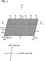
- FIG. 1 is a perspective view of the vehicular lamp fitting 10
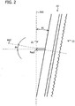
- FIG. 2 is a side view of the vehicular lamp fitting 10
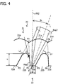
- FIG. 3 and FIG. 4 are cross-sectional views (partial) sectioned at A-A in FIG. 1 .
- the vehicular lamp fitting 10 illustrated in FIG. 1 is a signal lamp fitting (or sign lamp fitting), that is used as a tail lamp, a position lamp, a stop lamp, a turn signal lamp or the like, and is mounted on the left and right sides of the rear end of a vehicle (e.g. automobile) respectively.
- the vehicular lamp fittings 10 on the left and right sides are identical and mounted symmetrically, and therefore in the following, the vehicular lamp fitting 10 mounted on the right side on the rear end of the vehicle (right side facing the rear end of the vehicle), will be described.
- the vehicular lamp fitting 10 includes: a light guiding plate 20; and light sources 30 which emit light guided by the light guiding plate 20 (red light when the vehicular lamp fitting 10 is used as a tail lamp).
- the light source 30 is a semiconductor light-emitting element, such as an LED and LD, which includes a rectangular (e.g. 1-mm square) light-emitting surface, and is mounted on a substrate (not illustrated) in a state of the light-emitting surface facing an upper end face 23 of the light guiding plate 20.
- a plurality of light sources 30 are disposed along the upper end face 23 of the light guiding plate 20.
- the optical axis of the light source 30 extends in a first direction.
- the substrate is fixed on a housing (not illustrated) or the like by screws.
- the light guiding plate 20 is a light guiding plate including a front surface 21 and a back surface 22 on the opposite side of the front surface 21, and is an inner lens, for example.
- the light guiding plate 20 is a plate type (flat plate type) light guiding plate.
- the light guiding plate 20 is made of a transparent resin such as an acrylic resin or polycarbonate, and is molded by injection molding.
- the basic thickness of the light guiding plate 20 is 1 to 4 mm, for example.
- the light guiding plate 20 is disposed in an attitude that is inclined from the reference axis AX1, which extends in the vertical direction, by a predetermined receding angle ⁇ 1. In some cases the light guiding plate 20 may be disposed in an attitude that is inclined from the reference axis, which extends in the vehicle width direction, by a predetermined receding angle (not illustrated).
- the front surface 21 of the light guiding plate 20 includes a plurality of first light control surfaces 21a 1 to 21a n .
- the first light control surface 21a 1 to 21a n are disposed in parallel, extending in a same direction (first direction in FIG. 1 ).
- the first light control surfaces 21a 1 to 21a n are called the first light control surface 21a, unless distinction is necessary.
- the first light control surface 21a is a refracted surface which is configured such that the horizontal exit angle of the light Ray 1 from the light source 30 refracted and exited from the first light control surface 21 a is a predetermined angle ⁇ H .
- the dashed line indicated by AX2 in FIG. 3 is the reference axis which extends in the plate thickness direction of the light guiding plate 20. This reference axis is hereafter referred to as a reference axis AX2.
- the first light control surface 21a is, for example, a surface of which cross-section, at a plane orthogonal to the first direction is arc-shaped, which is convex toward the light-exiting direction (the light-emitting direction), that is a cylindrical surface of which cylindrical axis extends in the first direction.
- the first light control surface 21a is a focus plane configured such that the exit angle of the light Ray 2 (virtual ray), which is emitted from the focal point F and is refracted and exits from the first light control surface 21a, be a predetermined angle ⁇ H .
- Each angle ⁇ H of the first light control surfaces 21a 1 to 21a n may be the same or mutually different. Depending on the target light distribution pattern, an appropriate angle ⁇ H is selected.
- the focal point F is set in a vicinity of the second light control surface 22a.
- the focal point F is set on the line L, which is inclined from the reference axis AX2 by the angle ⁇ H , and is outside the light guiding plate 20.
- the focal point F is not limited to this position as long as the focal point is in vicinity of the second light control surface 22a, and may be inside the light guiding plate 20, or may at a position that deviates from the line L.
- the back surface 22 of the light guiding plate 20 includes a plurality of second light control surfaces 22a 1 to 22a n corresponding to the first light control surfaces 21a 1 to 21a n respectively, and a plurality of concave portions 22b 1 to 22b n each of which is disposed between the two adjacent second light control surfaces, out of the second light control surfaces 22a 1 to 22a n .
- the second light control surfaces 22a 1 to 22a n and the concave portions 22b 1 to 22b n are disposed in parallel, extending in a same direction (first direction in FIG. 1 ).
- the second light control surfaces 22a 1 to 22a n are called the second light control surface 22a, unless distinction is necessary.
- the concave portions 22b 1 to 22b n are called the concave portion 22b, unless distinction is necessary.
- the second light control surface 22a is a reflection surface which internally reflects the light from the light source 30, so that the exit angle of the light Ray 1 from the light source 30 in the vertical direction, which exits through the first light control surface 21a, becomes a predetermined angel ⁇ V (see FIG. 2 ).
- the second light control surface 22a is formed so as to be symmetrical with respect to the reference axis AX2, which passes through the intersection between: the line L which inclines from the reference axis AX2 by the angle ⁇ H ; and the second light control surface 22a, for example.
- the width W of the second light control surface 22a is preferably as small as possible, within the limits of the durability of the light guiding plate 20 and the easiness of injection molding (easiness of creating a mold).
- FIG. 5 is a perspective view of a cross-section (partial) at A-A in FIG. 1 .
- the second light control surface 22a includes a plurality of lens cut portions 22a1.
- the plurality of lens cut portions 22a1 are, for example, a plurality of V grooves which are disposed in parallel extending in the second direction orthogonal to the first direction.
- the lens cut portion 22a 1 is called a V groove 22a 1.
- the angle of the V groove 22a1 (angle between one line and the other line constituting the "V" shape) is set such that the exit angle of the light Ray 1 in the vertical direction from the light source 30, which exits through the first light control surface 21a, be a predetermined angle ⁇ V (see FIG. 2 ).
- Each angle ⁇ V of the second light control surfaces 22a 1 to 22a n may be the same or mutually different. Depending on the target light distribution pattern, an appropriate angle ⁇ V is selected.
- a concave portion 22b is disposed. Then the light Ray 3 from the light source 30, internally reflected on the second light control surface 22a, is blocked by the concave portion 22b (e.g. internally reflected by the concave portion 22b), hence the light Ray 3 exiting through the adjacent first light control surface 21a (adjacent to the left in FIG. 4 ), is suppressed. Further, the light from the light source 30, which is internally reflected by the concave portion 22b and exits through the first light control surface 21a, increases, therefore a vehicular lamp fitting, which efficiently forms a target light distribution pattern using less number of light sources 30, is implemented.
- the concave portion 22b is disposed in the light guiding plate 20 in a portion that does not block the light from the light source 30, which is internally reflected by the second light control surface 22a and exits from the first light control surface 21a.
- the concave portion 22b is disposed between the lines L1 and L2, and between the lines L3 and L4 in FIG. 4 .
- the concave portion 22b is an approximately a U-shaped concave portion of which bottom face is curved in an arc shape.
- the depth H of the concave portion 22b is preferably as deep as possible, within the limits of the durability of the light guiding plate 20, and easiness of injection molding (easiness of creating a mold).
- the line L1 is a line connecting: an intersection P1 between the first light control surface 21a at the center and a first light control surface 21a on the left side thereof; and a right end point P2 of a second light control surface 22a on the left side of the second light control surface 22a at the center.
- the line L2 is a line connecting: the intersection P1; and the left end point P3 of the second light control surface 22a at the center.
- the line L3 is a line connecting: an intersection P4 between the first light control surface 21a at the center and a first light control surface 21a on the right side thereof; and a right end point P5 of the second light control surface 22a at the center.
- the line L4 is a line connecting: the intersection P4; and the left end point P6 of a second light control surface 22a on the right side of the second light control surface 22a at the center.
- the light from the light source 30 enters the light guiding plate 20 through the upper end face 23 of the light guiding plate 20, and is internally reflected by the front surface 21 and the back surface 22 of the light guiding plate 20, whereby the light is guided toward the lower end face 24 of the light guiding plate 20 (that is, in the first direction).
- the first light control surface 21a is configured as a focus plane where the focal point F is set in the vicinity of the second light control surface 22a, hence, as illustrated in FIG. 3 , the exit angle of the light Ray 1 in the horizontal direction from the light source 30, which exits through the first light control surface 21a, is controlled to be a predetermined angle ⁇ H .
- the angle of the V groove 22a1 is set such that the exit angle of the light in the vertical direction from the light source 30, which exits through the first light control surface 21a, be a predetermined angle ⁇ V , hence, as illustrated in FIG. 2 , the exit angle of the light Ray 1 in the vertical direction from the light source 30, which exits through the first light control surface 21a, is controlled to be the predetermined angle ⁇ V .
- a target light distribution pattern having a luminous intensity distribution required for a tail lamp, a position lamp, a stop lamp and a turn signal lamp or the like, can be formed.
- a vehicular lamp fitting 10 which can control not only the exit angle of the light in the vertical direction from the light source 30, which exits through the surface 21 of the light guiding plate 20, but also the exit angle thereof in the horizontal direction, is provided.
- the light guiding plate 20 includes not only the second light control surface 22a, which control the exit angle of the light from the light source 30 in the vertical direction, which exited through the surface 21, but also the first light control surface 21a which controls the exit angle thereof in the horizontal direction.
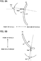
- FIG. 6A and FIG. 6B to FIG. 9 are diagrams for describing the modification of the light guiding plate 20.
- the second light control surface 22a is a surface orthogonal to the reference axis AX2, extending in the plate thickness direction of the light guiding plate 20, was described, but the present invention is not limited to this.
- the second light control surface 22a may be a surface orthogonal to the line L, which is inclined from the reference axis AX2 by the angle ⁇ H . Then the light from the light source 30, which exits through the first light control surface 21a (reflected light from the second light control surface 22a), can be increased.
- the first light control surface 21a is the focus I plane, in which the focal point F is set in the vicinity of the second light control surface 22a, was described, but the present invention is not limited to this.
- the first light control surface 21a may be an arc-shaped surface, of which shape is appropriately the same as the focus plane.
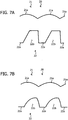
- the concave portion 22b is a concave portion having an approximately U shape, where the bottom surface is curved in an arc shape, was described, but the present invention is not limited to this.
- the concave portion 22b may be a concave portion having an approximately U shape, where the bottom surface includes corners.
- the concave portion 22b may be a concave portion having an approximately U shape, which is configured by only curved portions without including any linear portions.
- FIG. 8A is a side view of the light guiding plate 20 (modification) and FIG. 8B is a top view of the light guiding plate 20 (modification).
- the present invention is not limited to this.
- a light guiding plate 20 which is curved in the longitudinal direction, may be used, or as illustrated in FIG. 8B , a light guiding plate, which is curved in the lateral direction, may be used, or a light guiding plate, which is curved in the upper, lower, left and right directions (not illustrated), may be used.
- the vehicular lamp fitting 10 may be used in a state of rotating 90° to the left (or right).
Landscapes
- Physics & Mathematics (AREA)
- Engineering & Computer Science (AREA)
- General Engineering & Computer Science (AREA)
- Optics & Photonics (AREA)
- General Physics & Mathematics (AREA)
- Microelectronics & Electronic Packaging (AREA)
- Non-Portable Lighting Devices Or Systems Thereof (AREA)
- Planar Illumination Modules (AREA)
Abstract
Description
- The present invention relates to a vehicular lamp fitting, and more particularly to a vehicular lamp fitting that can control not only an exit angle of the light in the vertical direction, but also an exit angle of the light in the horizontal direction from a light source which emits light through the surface of a light guiding plate.
- A vehicular lamp fitting that includes: a light guiding plate having a front surface and a back surface on the opposite side of the front surface; and a light source which emits light guided by the light guiding plate, is known (e.g. Japanese Laid-open Patent Publication No.
2018-006226 - In the vehicular lamp fitting according to Japanese Laid-open Patent Publication No.
2018-006226 - In the vehicular lamp fitting according to Japanese Laid-open Patent Publication No.
2018-006226 - The present invention has been made in view of the above circumstances and has an object of providing a vehicular lamp fitting that can control not only an exit angle of the light in the vertical direction, but also an exit angle of the light in the horizontal direction from a light source which emits light through the surface of a light guiding plate.
- In order to achieve the first object described above, an aspect of the present invention provides a vehicular lamp fitting, comprising: a light guiding plate having a front surface and a back surface disposed on the opposite side of the front surface; and a light source which emits light guided by the light guiding plate, wherein the front surface includes a plurality of first light control surfaces, the back surface includes a plurality of second light control surfaces corresponding to the plurality of first light control surfaces respectively, and a plurality of concave portions each of which is disposed between two adjacent second light control surfaces out of the plurality of second light control surfaces, the plurality of first light control surfaces, the plurality of second light control surfaces and the plurality of concave portions are disposed in parallel, extending in a first direction respectively, the light source emits light which is guided in the first direction by the light guiding plate, is internally reflected by the second light control surface, and exits through the first light control surface, the first light control surface is a refraction surface which is configured such that the exit angle of the light from the light source in the horizontal direction or the vertical direction, which is refracted and exits through the first light control surface, be a predetermined angle, and the second light control surface is a reflection surface which is configured such that the exit angle of the light from the light source in the vertical direction or the horizontal direction, which exits through the first light control surface, be a predetermined angle.
- According to this aspect, a vehicular lamp fitting , which can control not only the exit angle of the light in the vertical direction (or the horizontal direction) from the light source, which exits through the surface of the
light guiding plate 20, but also the exit angle thereof in the horizontal direction (or the vertical direction), is provided. - This is because the light guiding plate includes not only the second light control surface, which control the exit angle of the light from the light source in the vertical direction (or the horizontal direction), which exited through the surface, but also the first light control surface which controls the exit angle thereof in the horizontal direction (or the vertical direction).
- In addition, in a preferred aspect of the invention described above, the first light control surface is a surface of which cross-section at a plane orthogonal to the first direction is an arc-shaped surface, which is convex toward the light-exiting direction.
- In addition, in a preferred aspect of the invention described above, the first light control surface is a focus plane configured such that the exit angle of the light in the horizontal direction or the vertical direction, which is emitted from a focus plane, and is refracted and exits through the first light control surface, be a predetermined angle, and the focal point is set in a vicinity of the second light control surface.
- In addition, in a preferred aspect of the invention described above, the concave portion is disposed in a portion of the light guiding plate, where the light from the light source, which is internally reflected by the second light control surface and exits through the first light control surface, is not blocked.
- In addition, in a preferred aspect of the invention described above, the second light control surface includes a plurality of lens cut portions, and the plurality of lens cut portions are a plurality of V grooves which are disposed in parallel, extending in a second direction orthogonal to the first direction.
- In addition, in a preferred aspect of the invention described above, the light guiding plate is curved at least in one of the longitudinal direction and the lateral directions.
-
-
FIG. 1 is a perspective view of the vehicular lamp fitting 10 -
FIG. 2 is a side view of the vehicular lamp fitting 10 -
FIG. 3 is a cross-sectional views (partial) sectioned at A-A inFIG. 1 -
FIG. 4 is a cross-sectional views (partial) sectioned at A-A inFIG. 1 -
FIG. 5 is a perspective view of a cross-section (partial) at A-A inFIG. 1 . -
FIG. 6A and FIG. 6B are diagrams for describing the modification of thelight guiding plate 20. -
FIG. 7A and FIG. 7B are diagrams for describing the modification of thelight guiding plate 20. -
FIG. 8A and FIG. 8B are diagrams for describing the modification of thelight guiding plate 20. -
FIG. 9 is a diagram for describing the modification of thelight guiding plate 20. - Hereinafter, a
vehicle lamp unit 10 that represents an embodiment of the present invention will be described with reference to the accompanying drawings. It should be noted that corresponding components in the respective drawings will be denoted by same reference signs and redundant descriptions thereof will be omitted. -
FIG. 1 is a perspective view of the vehicular lamp fitting 10,FIG. 2 is a side view of the vehicular lamp fitting 10, andFIG. 3 andFIG. 4 are cross-sectional views (partial) sectioned at A-A inFIG. 1 . - The vehicular lamp fitting 10 illustrated in
FIG. 1 is a signal lamp fitting (or sign lamp fitting), that is used as a tail lamp, a position lamp, a stop lamp, a turn signal lamp or the like, and is mounted on the left and right sides of the rear end of a vehicle (e.g. automobile) respectively. Thevehicular lamp fittings 10 on the left and right sides are identical and mounted symmetrically, and therefore in the following, the vehicular lamp fitting 10 mounted on the right side on the rear end of the vehicle (right side facing the rear end of the vehicle), will be described. - As illustrated in
FIG. 1 , thevehicular lamp fitting 10 includes: alight guiding plate 20; andlight sources 30 which emit light guided by the light guiding plate 20 (red light when thevehicular lamp fitting 10 is used as a tail lamp). - The
light source 30 is a semiconductor light-emitting element, such as an LED and LD, which includes a rectangular (e.g. 1-mm square) light-emitting surface, and is mounted on a substrate (not illustrated) in a state of the light-emitting surface facing anupper end face 23 of thelight guiding plate 20. For example, a plurality oflight sources 30 are disposed along theupper end face 23 of thelight guiding plate 20. The optical axis of thelight source 30 extends in a first direction. The substrate is fixed on a housing (not illustrated) or the like by screws. - As illustrated in
FIG. 2 , thelight guiding plate 20 is a light guiding plate including afront surface 21 and aback surface 22 on the opposite side of thefront surface 21, and is an inner lens, for example. The light guidingplate 20 is a plate type (flat plate type) light guiding plate. Thelight guiding plate 20 is made of a transparent resin such as an acrylic resin or polycarbonate, and is molded by injection molding. The basic thickness of thelight guiding plate 20 is 1 to 4 mm, for example. - The
light guiding plate 20 is disposed in an attitude that is inclined from the reference axis AX1, which extends in the vertical direction, by a predetermined receding angle θ1. In some cases thelight guiding plate 20 may be disposed in an attitude that is inclined from the reference axis, which extends in the vehicle width direction, by a predetermined receding angle (not illustrated). - As illustrated in
FIG. 1 , thefront surface 21 of thelight guiding plate 20 includes a plurality of firstlight control surfaces 21a1 to 21an. - The first
light control surface 21a1 to 21an are disposed in parallel, extending in a same direction (first direction inFIG. 1 ). In the following, the firstlight control surfaces 21a1 to 21an are called the firstlight control surface 21a, unless distinction is necessary. - As shown in
FIG. 3 , the firstlight control surface 21a is a refracted surface which is configured such that the horizontal exit angle of the light Ray 1 from thelight source 30 refracted and exited from the firstlight control surface 21 a is a predetermined angle θH. The dashed line indicated by AX2 inFIG. 3 is the reference axis which extends in the plate thickness direction of thelight guiding plate 20. This reference axis is hereafter referred to as a reference axis AX2. - The first
light control surface 21a is, for example, a surface of which cross-section, at a plane orthogonal to the first direction is arc-shaped, which is convex toward the light-exiting direction (the light-emitting direction), that is a cylindrical surface of which cylindrical axis extends in the first direction. - In concrete terms, as illustrated in
FIG. 4 , the firstlight control surface 21a is a focus plane configured such that the exit angle of the light Ray 2 (virtual ray), which is emitted from the focal point F and is refracted and exits from the firstlight control surface 21a, be a predetermined angle θH. Each angle θH of the firstlight control surfaces 21a1 to 21an may be the same or mutually different. Depending on the target light distribution pattern, an appropriate angle θH is selected. - The focal point F is set in a vicinity of the second
light control surface 22a. In concrete terms, the focal point F is set on the line L, which is inclined from the reference axis AX2 by the angle θH, and is outside thelight guiding plate 20. The focal point F is not limited to this position as long as the focal point is in vicinity of the secondlight control surface 22a, and may be inside thelight guiding plate 20, or may at a position that deviates from the line L. - As illustrated in
FIG. 1 , theback surface 22 of thelight guiding plate 20 includes a plurality of secondlight control surfaces 22a1 to 22an corresponding to the firstlight control surfaces 21a1 to 21an respectively, and a plurality ofconcave portions 22b1 to 22bn each of which is disposed between the two adjacent second light control surfaces, out of the secondlight control surfaces 22a1 to 22an. - The second
light control surfaces 22a1 to 22an and theconcave portions 22b1 to 22bn are disposed in parallel, extending in a same direction (first direction inFIG. 1 ). In the following, the secondlight control surfaces 22a1 to 22an are called the secondlight control surface 22a, unless distinction is necessary. Theconcave portions 22b1 to 22bn are called theconcave portion 22b, unless distinction is necessary. - The second
light control surface 22a is a reflection surface which internally reflects the light from thelight source 30, so that the exit angle of the light Ray 1 from thelight source 30 in the vertical direction, which exits through the firstlight control surface 21a, becomes a predetermined angel θV (seeFIG. 2 ). - As illustrated in
FIG. 4 , the secondlight control surface 22a is formed so as to be symmetrical with respect to the reference axis AX2, which passes through the intersection between: the line L which inclines from the reference axis AX2 by the angle θH; and the secondlight control surface 22a, for example. The width W of the secondlight control surface 22a is preferably as small as possible, within the limits of the durability of thelight guiding plate 20 and the easiness of injection molding (easiness of creating a mold). -
FIG. 5 is a perspective view of a cross-section (partial) at A-A inFIG. 1 . - As illustrated in
FIG. 5 , the secondlight control surface 22a includes a plurality of lens cut portions 22a1. The plurality of lens cut portions 22a1 are, for example, a plurality of V grooves which are disposed in parallel extending in the second direction orthogonal to the first direction. In the following, the lens cutportion 22a 1 is called aV groove 22a 1. The angle of the V groove 22a1 (angle between one line and the other line constituting the "V" shape) is set such that the exit angle of the light Ray 1 in the vertical direction from thelight source 30, which exits through the firstlight control surface 21a, be a predetermined angle θV (seeFIG. 2 ). Each angle θV of the secondlight control surfaces 22a1 to 22an may be the same or mutually different. Depending on the target light distribution pattern, an appropriate angle θV is selected. - As illustrated in
FIG. 4 , when thelight Ray 3 from thelight source 30, internally reflected on the secondlight control surface 22a, exits through the adjacent firstlight control surface 21a (adjacent to the left inFIG. 4 ), it becomes uncontrolled light and causes glare etc. - Therefore in order to suppress the
light Ray 3 from thelight source 30, which is internally reflected on the secondlight control surface 22a, exiting through the adjacent firstlight control surface 21a (adjacent to the left inFIG. 4 ), aconcave portion 22b is disposed. Then thelight Ray 3 from thelight source 30, internally reflected on the secondlight control surface 22a, is blocked by theconcave portion 22b (e.g. internally reflected by theconcave portion 22b), hence thelight Ray 3 exiting through the adjacent firstlight control surface 21a (adjacent to the left inFIG. 4 ), is suppressed. Further, the light from thelight source 30, which is internally reflected by theconcave portion 22b and exits through the firstlight control surface 21a, increases, therefore a vehicular lamp fitting, which efficiently forms a target light distribution pattern using less number oflight sources 30, is implemented. - The
concave portion 22b is disposed in thelight guiding plate 20 in a portion that does not block the light from thelight source 30, which is internally reflected by the secondlight control surface 22a and exits from the firstlight control surface 21a. In concrete terms, theconcave portion 22b is disposed between the lines L1 and L2, and between the lines L3 and L4 inFIG. 4 . Theconcave portion 22b is an approximately a U-shaped concave portion of which bottom face is curved in an arc shape. The depth H of theconcave portion 22b is preferably as deep as possible, within the limits of the durability of thelight guiding plate 20, and easiness of injection molding (easiness of creating a mold). - As illustrated in
FIG. 4 , the line L1 is a line connecting: an intersection P1 between the firstlight control surface 21a at the center and a firstlight control surface 21a on the left side thereof; and a right end point P2 of a secondlight control surface 22a on the left side of the secondlight control surface 22a at the center. The line L2 is a line connecting: the intersection P1; and the left end point P3 of the secondlight control surface 22a at the center. In the same manner, the line L3 is a line connecting: an intersection P4 between the firstlight control surface 21a at the center and a firstlight control surface 21a on the right side thereof; and a right end point P5 of the secondlight control surface 22a at the center. The line L4 is a line connecting: the intersection P4; and the left end point P6 of a secondlight control surface 22a on the right side of the secondlight control surface 22a at the center. - In the case of the vehicular lamp fitting 10 having the above mentioned configuration, when the
light source 30 is turned ON, the light from thelight source 30 enters thelight guiding plate 20 through the upper end face 23 of thelight guiding plate 20, and is internally reflected by thefront surface 21 and theback surface 22 of thelight guiding plate 20, whereby the light is guided toward thelower end face 24 of the light guiding plate 20 (that is, in the first direction). - A part of the light from the
light source 30, which is guided inside thelight guiding plate 20, is internally reflected by the secondlight control surface 22a (V groove 22a1), disposed on theback surface 22 of thelight guiding plate 20, and exits through the firstlight control surface 21a. - The first
light control surface 21a is configured as a focus plane where the focal point F is set in the vicinity of the secondlight control surface 22a, hence, as illustrated inFIG. 3 , the exit angle of the light Ray 1 in the horizontal direction from thelight source 30, which exits through the firstlight control surface 21a, is controlled to be a predetermined angle θH. - The angle of the V groove 22a1 is set such that the exit angle of the light in the vertical direction from the
light source 30, which exits through the firstlight control surface 21a, be a predetermined angle θV, hence, as illustrated inFIG. 2 , the exit angle of the light Ray 1 in the vertical direction from thelight source 30, which exits through the firstlight control surface 21a, is controlled to be the predetermined angle θV. - By controlling the exit angles of the light in the horizontal direction and the vertical direction from the
light source 30, which exits through the firstlight control surfaces 21a1 to 21an respectively, a target light distribution pattern having a luminous intensity distribution required for a tail lamp, a position lamp, a stop lamp and a turn signal lamp or the like, can be formed. - As described above, according to this embodiment, a vehicular lamp fitting 10, which can control not only the exit angle of the light in the vertical direction from the
light source 30, which exits through thesurface 21 of thelight guiding plate 20, but also the exit angle thereof in the horizontal direction, is provided. - This is because the
light guiding plate 20 includes not only the secondlight control surface 22a, which control the exit angle of the light from thelight source 30 in the vertical direction, which exited through thesurface 21, but also the firstlight control surface 21a which controls the exit angle thereof in the horizontal direction. - A modification will be described next.
-
FIG. 6A and FIG. 6B toFIG. 9 are diagrams for describing the modification of thelight guiding plate 20. - In the above mentioned embodiment, an example when the second
light control surface 22a is a surface orthogonal to the reference axis AX2, extending in the plate thickness direction of thelight guiding plate 20, was described, but the present invention is not limited to this. For example, as illustrated inFIG. 6A , the secondlight control surface 22a may be a surface orthogonal to the line L, which is inclined from the reference axis AX2 by the angle θH. Then the light from thelight source 30, which exits through the firstlight control surface 21a (reflected light from the secondlight control surface 22a), can be increased. - In the above mentioned embodiment, an example when the first
light control surface 21a is the focus I plane, in which the focal point F is set in the vicinity of the secondlight control surface 22a, was described, but the present invention is not limited to this. For example, as illustrated inFIG. 6B , the firstlight control surface 21a may be an arc-shaped surface, of which shape is appropriately the same as the focus plane. - In the above mentioned embodiment, an example when the
concave portion 22b is a concave portion having an approximately U shape, where the bottom surface is curved in an arc shape, was described, but the present invention is not limited to this. For example, as illustrated inFIG. 7A , theconcave portion 22b may be a concave portion having an approximately U shape, where the bottom surface includes corners. Further, as illustrated inFIG. 7B , theconcave portion 22b may be a concave portion having an approximately U shape, which is configured by only curved portions without including any linear portions. -
FIG. 8A is a side view of the light guiding plate 20 (modification) andFIG. 8B is a top view of the light guiding plate 20 (modification). - In the above mentioned embodiment, an example when the
light guiding plate 20 is a plane type light guiding plate, was described, but the present invention is not limited to this. For example, as illustrated inFIG. 8A , alight guiding plate 20, which is curved in the longitudinal direction, may be used, or as illustrated inFIG. 8B , a light guiding plate, which is curved in the lateral direction, may be used, or a light guiding plate, which is curved in the upper, lower, left and right directions (not illustrated), may be used. - As illustrated in
FIG. 9 , the vehicular lamp fitting 10 may be used in a state of rotating 90° to the left (or right). - All the numeric values of each of the embodiments are given only for illustration purpose, and appropriate numeric values different from these numeric values can be, of course, used.
- Each of the embodiments is given only for illustration purpose in all respects. The present invention is not limited to each of the embodiments in its interpretation. The present invention can be carried out in various ways without departing from its spirit or principal feature.
Claims (7)
- A vehicular lamp fitting, comprising:a light guiding plate (20) having a front surface (21) and a back surface (22) disposed on the opposite side of the front surface; anda light source (30) which emits light guided by the light guiding plate, whereinthe front surface includes a plurality of first light control surfaces (21a1 - 21an),the back surface includes a plurality of second light control surfaces (22a1 - 22an) corresponding to the plurality of first light control surfaces respectively, and a plurality of concave portions (22b1 - 22bn) each of which is disposed between two adjacent second light control surfaces out of the plurality of second light control surfaces,the plurality of first light control surfaces, the plurality of second light control surfaces and the plurality of concave portions are disposed in parallel, extending in a first direction respectively,the light source emits light which is guided in the first direction by the light guiding plate, is internally reflected by the second light control surface, and exits through the first light control surface,the first light control surface is a refraction surface which is configured such that the exit angle (θH) of the light from the light source in one of the horizontal direction and the vertical direction, which is refracted and exits through the first light control surface, be a predetermined angle, andthe second light control surface is a reflection surface which is configured such that the exit angle (θV) of the light from the light source in the other of the vertical direction and the horizontal direction, which exits through the first light control surface, be a predetermined angle.
- The vehicular lamp fitting according to claim 1, wherein the first light control surface is a surface of which cross-section at a plane orthogonal to the first direction is an arc-shaped surface, which is convex toward the light-exiting direction.
- The vehicular lamp fitting according to claim 1, wherein
the first light control surface is a focus plane configured such that the exit angle of the light in the horizontal direction or the vertical direction, which is emitted from a focus point, and is refracted and exits through the first light control surface, be a predetermined angle, and
the focal point is set in a vicinity of the second light control surface. - The vehicular lamp fitting according to any one of claims 1, wherein the concave portion is disposed in a portion of the light guiding plate, where the light from the light source, which is internally reflected by the second light control surface and exits through the first light control surface, is not blocked.
- The vehicular lamp fitting according to any one of claims 1, wherein
the second light control surface includes a plurality of lens cut portions, and
the plurality of lens cut portions are a plurality of V grooves which are disposed in parallel, extending in a second direction orthogonal to the first direction. - The vehicular lamp fitting according to any one of claims 1, wherein the light guiding plate is curved at least in one of the longitudinal direction and the lateral directions.
- A vehicular lamp fitting, comprising:a light guiding plate (20) having a front surface (21) and a back surface (22) disposed on the opposite side of the front surface; anda light source (30) which emits light guided by the light guiding plate, whereinthe front surface includes at least one first light control surface (21a1 - 21an),the back surface includes at least one second light control surface (22a1 - 22an) corresponding to the first light control surface,the light source emits light which is guided by the light guiding plate, is internally reflected by the second light control surface, and exits through the first light control surface,the first light control surface is a refraction surface which is configured such that the exit angle (θH) of the light from the light source in one of the horizontal direction and the vertical direction, which is refracted and exits through the first light control surface, be a predetermined angle, andthe second light control surface is a reflection surface which is configured such that the exit angle (θV) of the light from the light source in the other of the vertical direction and the horizontal direction, which exits through the first light control surface, be a predetermined angle.
Applications Claiming Priority (1)
| Application Number | Priority Date | Filing Date | Title |
|---|---|---|---|
| JP2018117933A JP7277004B2 (en) | 2018-06-21 | 2018-06-21 | vehicle lamp |
Publications (2)
| Publication Number | Publication Date |
|---|---|
| EP3587909A1 true EP3587909A1 (en) | 2020-01-01 |
| EP3587909B1 EP3587909B1 (en) | 2022-09-14 |
Family
ID=66999673
Family Applications (1)
| Application Number | Title | Priority Date | Filing Date |
|---|---|---|---|
| EP19181380.7A Active EP3587909B1 (en) | 2018-06-21 | 2019-06-19 | Vehicular lamp fitting |
Country Status (3)
| Country | Link |
|---|---|
| US (1) | US10738959B2 (en) |
| EP (1) | EP3587909B1 (en) |
| JP (1) | JP7277004B2 (en) |
Families Citing this family (2)
| Publication number | Priority date | Publication date | Assignee | Title |
|---|---|---|---|---|
| JP7579744B2 (en) * | 2021-04-19 | 2024-11-08 | 株式会社小糸製作所 | Vehicle lighting fixtures |
| WO2026074606A1 (en) * | 2024-10-01 | 2026-04-09 | ヤマハ発動機株式会社 | Vehicle and lighting element used in the vehicle |
Citations (6)
| Publication number | Priority date | Publication date | Assignee | Title |
|---|---|---|---|---|
| JPS5943234U (en) * | 1982-09-14 | 1984-03-21 | セントラル自動車株式会社 | lamp cover |
| DE20318691U1 (en) * | 2003-12-03 | 2004-02-26 | Sidler Gmbh & Co. | Light for motor vehicles, has light conductor with steps on outer curved side that viewed towards end output coupling surface are set back and each has end output coupling surface |
| JP2005327649A (en) * | 2004-05-17 | 2005-11-24 | Koito Mfg Co Ltd | Vehicle lamp unit and vehicle lamp |
| US20100002466A1 (en) * | 2008-07-03 | 2010-01-07 | Kim Sang-Soo | Light guide plate and backlight unit having same |
| FR2948174A1 (en) * | 2009-07-17 | 2011-01-21 | Franck Andre Marie Guigan | Luminous wall for lamp of product, has deflector whose light beam is deflected toward convergent optical device, and luminous ray assembly carried from side face to another side face of light input area through light guide |
| US20140140084A1 (en) * | 2012-11-22 | 2014-05-22 | Automotive Lighting Reutlingen Gmbh | Motor vehicle light with a light conductor and a shield that is visible through the light conductor |
Family Cites Families (13)
| Publication number | Priority date | Publication date | Assignee | Title |
|---|---|---|---|---|
| TWM317025U (en) * | 2007-02-09 | 2007-08-11 | K Bridge Electronics Co Ltd | Backlight module |
| CN101295038A (en) * | 2007-04-27 | 2008-10-29 | 鸿富锦精密工业(深圳)有限公司 | Backlight module and its optical board |
| US7568828B2 (en) * | 2007-11-05 | 2009-08-04 | Radiant Opto-Electronics Corp. | Light guide plate with compensated emission light field |
| CN101551479A (en) * | 2008-04-01 | 2009-10-07 | 鸿富锦精密工业(深圳)有限公司 | Prism sheet |
| US20110090713A1 (en) * | 2008-07-08 | 2011-04-21 | Helio Optoelectronics Corporation | Flexible backlight module |
| TW201323783A (en) * | 2011-12-12 | 2013-06-16 | Tyc Brother Ind Co Ltd | Light guide device for vehicle |
| JP2015092434A (en) * | 2012-02-24 | 2015-05-14 | シャープ株式会社 | Backlight unit and liquid crystal display device |
| JP6136201B2 (en) * | 2012-11-06 | 2017-05-31 | 凸版印刷株式会社 | Light guide, lighting device, display device |
| TWI472817B (en) * | 2013-04-30 | 2015-02-11 | Radiant Opto Electronics Corp | A light guide means and a backlight module having the light guide means |
| US9046225B2 (en) * | 2013-08-16 | 2015-06-02 | General Electric Company | Lighting system with improved illumination distribution |
| JP6311988B2 (en) * | 2014-10-21 | 2018-04-18 | オムロン株式会社 | Light guide plate and surface light source device |
| JP6758961B2 (en) | 2016-07-06 | 2020-09-23 | 株式会社小糸製作所 | Lighting equipment |
| JP2018063890A (en) * | 2016-10-13 | 2018-04-19 | 株式会社小糸製作所 | Lamp |
-
2018
- 2018-06-21 JP JP2018117933A patent/JP7277004B2/en active Active
-
2019
- 2019-06-11 US US16/438,035 patent/US10738959B2/en active Active
- 2019-06-19 EP EP19181380.7A patent/EP3587909B1/en active Active
Patent Citations (6)
| Publication number | Priority date | Publication date | Assignee | Title |
|---|---|---|---|---|
| JPS5943234U (en) * | 1982-09-14 | 1984-03-21 | セントラル自動車株式会社 | lamp cover |
| DE20318691U1 (en) * | 2003-12-03 | 2004-02-26 | Sidler Gmbh & Co. | Light for motor vehicles, has light conductor with steps on outer curved side that viewed towards end output coupling surface are set back and each has end output coupling surface |
| JP2005327649A (en) * | 2004-05-17 | 2005-11-24 | Koito Mfg Co Ltd | Vehicle lamp unit and vehicle lamp |
| US20100002466A1 (en) * | 2008-07-03 | 2010-01-07 | Kim Sang-Soo | Light guide plate and backlight unit having same |
| FR2948174A1 (en) * | 2009-07-17 | 2011-01-21 | Franck Andre Marie Guigan | Luminous wall for lamp of product, has deflector whose light beam is deflected toward convergent optical device, and luminous ray assembly carried from side face to another side face of light input area through light guide |
| US20140140084A1 (en) * | 2012-11-22 | 2014-05-22 | Automotive Lighting Reutlingen Gmbh | Motor vehicle light with a light conductor and a shield that is visible through the light conductor |
Also Published As
| Publication number | Publication date |
|---|---|
| US10738959B2 (en) | 2020-08-11 |
| JP2019220384A (en) | 2019-12-26 |
| EP3587909B1 (en) | 2022-09-14 |
| JP7277004B2 (en) | 2023-05-18 |
| US20190390837A1 (en) | 2019-12-26 |
Similar Documents
| Publication | Publication Date | Title |
|---|---|---|
| US10036526B2 (en) | Light guiding lens and vehicle lighting unit | |
| US8752990B2 (en) | Vehicle light | |
| CN107101178B (en) | Light guide assembly and lighting and/or signalling device | |
| EP2957824B1 (en) | Vehicle lighting unit | |
| US9958124B2 (en) | Vehicular lamp | |
| EP2990720A1 (en) | Vehicle lighting unit | |
| US20160195230A1 (en) | Lighting system, in particular for a motor vehicle lighting member, comprising a printed circuit board in the plane of the lighting direction | |
| US10767827B2 (en) | LED lighting device | |
| US8529109B2 (en) | Vehicle lightening unit | |
| US11047542B2 (en) | Light distribution member, lighting or signaling device and motor vehicle | |
| US20210071843A1 (en) | Optical device for modifying a light distribution | |
| EP3207307B1 (en) | Light guiding device and vehicle lamp | |
| EP3587909B1 (en) | Vehicular lamp fitting | |
| JP2016091825A (en) | Vehicular lamp | |
| JP6785673B2 (en) | Vehicle lighting | |
| EP3193077B1 (en) | Light flux control member, light-emitting device, and illumination device | |
| JP2016157542A (en) | Vehicular lighting fixture | |
| US20220003380A1 (en) | Vehicle lamp | |
| US10208926B2 (en) | Vehicular lamp | |
| EP3875853B1 (en) | Vehicle lamp | |
| US20230324021A1 (en) | Lighting tool for vehicle | |
| CN107676732B (en) | Light patterning device and lighting and/or signaling device | |
| EP4491941B1 (en) | Signaling device for a vehicle, in particular a motor vehicle | |
| JP4428664B2 (en) | Light guide plate | |
| WO2023247799A1 (en) | Light guide, optical irradiation assembly, and motor vehicle |
Legal Events
| Date | Code | Title | Description |
|---|---|---|---|
| PUAI | Public reference made under article 153(3) epc to a published international application that has entered the european phase |
Free format text: ORIGINAL CODE: 0009012 |
|
| STAA | Information on the status of an ep patent application or granted ep patent |
Free format text: STATUS: THE APPLICATION HAS BEEN PUBLISHED |
|
| AK | Designated contracting states |
Kind code of ref document: A1 Designated state(s): AL AT BE BG CH CY CZ DE DK EE ES FI FR GB GR HR HU IE IS IT LI LT LU LV MC MK MT NL NO PL PT RO RS SE SI SK SM TR |
|
| AX | Request for extension of the european patent |
Extension state: BA ME |
|
| STAA | Information on the status of an ep patent application or granted ep patent |
Free format text: STATUS: REQUEST FOR EXAMINATION WAS MADE |
|
| 17P | Request for examination filed |
Effective date: 20200318 |
|
| RBV | Designated contracting states (corrected) |
Designated state(s): AL AT BE BG CH CY CZ DE DK EE ES FI FR GB GR HR HU IE IS IT LI LT LU LV MC MK MT NL NO PL PT RO RS SE SI SK SM TR |
|
| GRAP | Despatch of communication of intention to grant a patent |
Free format text: ORIGINAL CODE: EPIDOSNIGR1 |
|
| STAA | Information on the status of an ep patent application or granted ep patent |
Free format text: STATUS: GRANT OF PATENT IS INTENDED |
|
| INTG | Intention to grant announced |
Effective date: 20220511 |
|
| GRAS | Grant fee paid |
Free format text: ORIGINAL CODE: EPIDOSNIGR3 |
|
| GRAA | (expected) grant |
Free format text: ORIGINAL CODE: 0009210 |
|
| STAA | Information on the status of an ep patent application or granted ep patent |
Free format text: STATUS: THE PATENT HAS BEEN GRANTED |
|
| AK | Designated contracting states |
Kind code of ref document: B1 Designated state(s): AL AT BE BG CH CY CZ DE DK EE ES FI FR GB GR HR HU IE IS IT LI LT LU LV MC MK MT NL NO PL PT RO RS SE SI SK SM TR |
|
| REG | Reference to a national code |
Ref country code: GB Ref legal event code: FG4D |
|
| REG | Reference to a national code |
Ref country code: CH Ref legal event code: EP |
|
| REG | Reference to a national code |
Ref country code: DE Ref legal event code: R096 Ref document number: 602019019500 Country of ref document: DE |
|
| REG | Reference to a national code |
Ref country code: IE Ref legal event code: FG4D |
|
| REG | Reference to a national code |
Ref country code: AT Ref legal event code: REF Ref document number: 1518902 Country of ref document: AT Kind code of ref document: T Effective date: 20221015 |
|
| REG | Reference to a national code |
Ref country code: LT Ref legal event code: MG9D |
|
| REG | Reference to a national code |
Ref country code: NL Ref legal event code: MP Effective date: 20220914 |
|
| PG25 | Lapsed in a contracting state [announced via postgrant information from national office to epo] |
Ref country code: SE Free format text: LAPSE BECAUSE OF FAILURE TO SUBMIT A TRANSLATION OF THE DESCRIPTION OR TO PAY THE FEE WITHIN THE PRESCRIBED TIME-LIMIT Effective date: 20220914 Ref country code: RS Free format text: LAPSE BECAUSE OF FAILURE TO SUBMIT A TRANSLATION OF THE DESCRIPTION OR TO PAY THE FEE WITHIN THE PRESCRIBED TIME-LIMIT Effective date: 20220914 Ref country code: NO Free format text: LAPSE BECAUSE OF FAILURE TO SUBMIT A TRANSLATION OF THE DESCRIPTION OR TO PAY THE FEE WITHIN THE PRESCRIBED TIME-LIMIT Effective date: 20221214 Ref country code: LV Free format text: LAPSE BECAUSE OF FAILURE TO SUBMIT A TRANSLATION OF THE DESCRIPTION OR TO PAY THE FEE WITHIN THE PRESCRIBED TIME-LIMIT Effective date: 20220914 Ref country code: LT Free format text: LAPSE BECAUSE OF FAILURE TO SUBMIT A TRANSLATION OF THE DESCRIPTION OR TO PAY THE FEE WITHIN THE PRESCRIBED TIME-LIMIT Effective date: 20220914 Ref country code: FI Free format text: LAPSE BECAUSE OF FAILURE TO SUBMIT A TRANSLATION OF THE DESCRIPTION OR TO PAY THE FEE WITHIN THE PRESCRIBED TIME-LIMIT Effective date: 20220914 |
|
| REG | Reference to a national code |
Ref country code: AT Ref legal event code: MK05 Ref document number: 1518902 Country of ref document: AT Kind code of ref document: T Effective date: 20220914 |
|
| PG25 | Lapsed in a contracting state [announced via postgrant information from national office to epo] |
Ref country code: HR Free format text: LAPSE BECAUSE OF FAILURE TO SUBMIT A TRANSLATION OF THE DESCRIPTION OR TO PAY THE FEE WITHIN THE PRESCRIBED TIME-LIMIT Effective date: 20220914 Ref country code: GR Free format text: LAPSE BECAUSE OF FAILURE TO SUBMIT A TRANSLATION OF THE DESCRIPTION OR TO PAY THE FEE WITHIN THE PRESCRIBED TIME-LIMIT Effective date: 20221215 |
|
| PG25 | Lapsed in a contracting state [announced via postgrant information from national office to epo] |
Ref country code: SM Free format text: LAPSE BECAUSE OF FAILURE TO SUBMIT A TRANSLATION OF THE DESCRIPTION OR TO PAY THE FEE WITHIN THE PRESCRIBED TIME-LIMIT Effective date: 20220914 Ref country code: RO Free format text: LAPSE BECAUSE OF FAILURE TO SUBMIT A TRANSLATION OF THE DESCRIPTION OR TO PAY THE FEE WITHIN THE PRESCRIBED TIME-LIMIT Effective date: 20220914 Ref country code: PT Free format text: LAPSE BECAUSE OF FAILURE TO SUBMIT A TRANSLATION OF THE DESCRIPTION OR TO PAY THE FEE WITHIN THE PRESCRIBED TIME-LIMIT Effective date: 20230116 Ref country code: ES Free format text: LAPSE BECAUSE OF FAILURE TO SUBMIT A TRANSLATION OF THE DESCRIPTION OR TO PAY THE FEE WITHIN THE PRESCRIBED TIME-LIMIT Effective date: 20220914 Ref country code: CZ Free format text: LAPSE BECAUSE OF FAILURE TO SUBMIT A TRANSLATION OF THE DESCRIPTION OR TO PAY THE FEE WITHIN THE PRESCRIBED TIME-LIMIT Effective date: 20220914 Ref country code: AT Free format text: LAPSE BECAUSE OF FAILURE TO SUBMIT A TRANSLATION OF THE DESCRIPTION OR TO PAY THE FEE WITHIN THE PRESCRIBED TIME-LIMIT Effective date: 20220914 |
|
| PG25 | Lapsed in a contracting state [announced via postgrant information from national office to epo] |
Ref country code: SK Free format text: LAPSE BECAUSE OF FAILURE TO SUBMIT A TRANSLATION OF THE DESCRIPTION OR TO PAY THE FEE WITHIN THE PRESCRIBED TIME-LIMIT Effective date: 20220914 Ref country code: PL Free format text: LAPSE BECAUSE OF FAILURE TO SUBMIT A TRANSLATION OF THE DESCRIPTION OR TO PAY THE FEE WITHIN THE PRESCRIBED TIME-LIMIT Effective date: 20220914 Ref country code: IS Free format text: LAPSE BECAUSE OF FAILURE TO SUBMIT A TRANSLATION OF THE DESCRIPTION OR TO PAY THE FEE WITHIN THE PRESCRIBED TIME-LIMIT Effective date: 20230114 Ref country code: EE Free format text: LAPSE BECAUSE OF FAILURE TO SUBMIT A TRANSLATION OF THE DESCRIPTION OR TO PAY THE FEE WITHIN THE PRESCRIBED TIME-LIMIT Effective date: 20220914 |
|
| REG | Reference to a national code |
Ref country code: DE Ref legal event code: R097 Ref document number: 602019019500 Country of ref document: DE |
|
| PG25 | Lapsed in a contracting state [announced via postgrant information from national office to epo] |
Ref country code: NL Free format text: LAPSE BECAUSE OF FAILURE TO SUBMIT A TRANSLATION OF THE DESCRIPTION OR TO PAY THE FEE WITHIN THE PRESCRIBED TIME-LIMIT Effective date: 20220914 Ref country code: AL Free format text: LAPSE BECAUSE OF FAILURE TO SUBMIT A TRANSLATION OF THE DESCRIPTION OR TO PAY THE FEE WITHIN THE PRESCRIBED TIME-LIMIT Effective date: 20220914 |
|
| PLBE | No opposition filed within time limit |
Free format text: ORIGINAL CODE: 0009261 |
|
| STAA | Information on the status of an ep patent application or granted ep patent |
Free format text: STATUS: NO OPPOSITION FILED WITHIN TIME LIMIT |
|
| PG25 | Lapsed in a contracting state [announced via postgrant information from national office to epo] |
Ref country code: DK Free format text: LAPSE BECAUSE OF FAILURE TO SUBMIT A TRANSLATION OF THE DESCRIPTION OR TO PAY THE FEE WITHIN THE PRESCRIBED TIME-LIMIT Effective date: 20220914 |
|
| 26N | No opposition filed |
Effective date: 20230615 |
|
| PG25 | Lapsed in a contracting state [announced via postgrant information from national office to epo] |
Ref country code: SI Free format text: LAPSE BECAUSE OF FAILURE TO SUBMIT A TRANSLATION OF THE DESCRIPTION OR TO PAY THE FEE WITHIN THE PRESCRIBED TIME-LIMIT Effective date: 20220914 |
|
| PG25 | Lapsed in a contracting state [announced via postgrant information from national office to epo] |
Ref country code: MC Free format text: LAPSE BECAUSE OF FAILURE TO SUBMIT A TRANSLATION OF THE DESCRIPTION OR TO PAY THE FEE WITHIN THE PRESCRIBED TIME-LIMIT Effective date: 20220914 |
|
| PG25 | Lapsed in a contracting state [announced via postgrant information from national office to epo] |
Ref country code: MC Free format text: LAPSE BECAUSE OF FAILURE TO SUBMIT A TRANSLATION OF THE DESCRIPTION OR TO PAY THE FEE WITHIN THE PRESCRIBED TIME-LIMIT Effective date: 20220914 |
|
| REG | Reference to a national code |
Ref country code: CH Ref legal event code: PL |
|
| REG | Reference to a national code |
Ref country code: BE Ref legal event code: MM Effective date: 20230630 |
|
| PG25 | Lapsed in a contracting state [announced via postgrant information from national office to epo] |
Ref country code: LU Free format text: LAPSE BECAUSE OF NON-PAYMENT OF DUE FEES Effective date: 20230619 |
|
| REG | Reference to a national code |
Ref country code: IE Ref legal event code: MM4A |
|
| PG25 | Lapsed in a contracting state [announced via postgrant information from national office to epo] |
Ref country code: LU Free format text: LAPSE BECAUSE OF NON-PAYMENT OF DUE FEES Effective date: 20230619 |
|
| PG25 | Lapsed in a contracting state [announced via postgrant information from national office to epo] |
Ref country code: IE Free format text: LAPSE BECAUSE OF NON-PAYMENT OF DUE FEES Effective date: 20230619 |
|
| PG25 | Lapsed in a contracting state [announced via postgrant information from national office to epo] |
Ref country code: IE Free format text: LAPSE BECAUSE OF NON-PAYMENT OF DUE FEES Effective date: 20230619 Ref country code: CH Free format text: LAPSE BECAUSE OF NON-PAYMENT OF DUE FEES Effective date: 20230630 |
|
| PG25 | Lapsed in a contracting state [announced via postgrant information from national office to epo] |
Ref country code: IT Free format text: LAPSE BECAUSE OF FAILURE TO SUBMIT A TRANSLATION OF THE DESCRIPTION OR TO PAY THE FEE WITHIN THE PRESCRIBED TIME-LIMIT Effective date: 20220914 Ref country code: BE Free format text: LAPSE BECAUSE OF NON-PAYMENT OF DUE FEES Effective date: 20230630 |
|
| PG25 | Lapsed in a contracting state [announced via postgrant information from national office to epo] |
Ref country code: BG Free format text: LAPSE BECAUSE OF FAILURE TO SUBMIT A TRANSLATION OF THE DESCRIPTION OR TO PAY THE FEE WITHIN THE PRESCRIBED TIME-LIMIT Effective date: 20220914 |
|
| PG25 | Lapsed in a contracting state [announced via postgrant information from national office to epo] |
Ref country code: BG Free format text: LAPSE BECAUSE OF FAILURE TO SUBMIT A TRANSLATION OF THE DESCRIPTION OR TO PAY THE FEE WITHIN THE PRESCRIBED TIME-LIMIT Effective date: 20220914 |
|
| PG25 | Lapsed in a contracting state [announced via postgrant information from national office to epo] |
Ref country code: CY Free format text: LAPSE BECAUSE OF FAILURE TO SUBMIT A TRANSLATION OF THE DESCRIPTION OR TO PAY THE FEE WITHIN THE PRESCRIBED TIME-LIMIT; INVALID AB INITIO Effective date: 20190619 |
|
| PG25 | Lapsed in a contracting state [announced via postgrant information from national office to epo] |
Ref country code: HU Free format text: LAPSE BECAUSE OF FAILURE TO SUBMIT A TRANSLATION OF THE DESCRIPTION OR TO PAY THE FEE WITHIN THE PRESCRIBED TIME-LIMIT; INVALID AB INITIO Effective date: 20190619 |
|
| PG25 | Lapsed in a contracting state [announced via postgrant information from national office to epo] |
Ref country code: TR Free format text: LAPSE BECAUSE OF FAILURE TO SUBMIT A TRANSLATION OF THE DESCRIPTION OR TO PAY THE FEE WITHIN THE PRESCRIBED TIME-LIMIT Effective date: 20220914 |
|
| PGFP | Annual fee paid to national office [announced via postgrant information from national office to epo] |
Ref country code: GB Payment date: 20260505 Year of fee payment: 8 |
|
| PGFP | Annual fee paid to national office [announced via postgrant information from national office to epo] |
Ref country code: DE Payment date: 20260430 Year of fee payment: 8 |
|
| PGFP | Annual fee paid to national office [announced via postgrant information from national office to epo] |
Ref country code: FR Payment date: 20260511 Year of fee payment: 8 |