EP3587903A1 - Vehicular headlight - Google Patents
Vehicular headlight Download PDFInfo
- Publication number
- EP3587903A1 EP3587903A1 EP18757708.5A EP18757708A EP3587903A1 EP 3587903 A1 EP3587903 A1 EP 3587903A1 EP 18757708 A EP18757708 A EP 18757708A EP 3587903 A1 EP3587903 A1 EP 3587903A1
- Authority
- EP
- European Patent Office
- Prior art keywords
- light source
- fan
- lamp
- drive circuit
- heat sink
- Prior art date
- Legal status (The legal status is an assumption and is not a legal conclusion. Google has not performed a legal analysis and makes no representation as to the accuracy of the status listed.)
- Withdrawn
Links
- 230000003287 optical effect Effects 0.000 claims description 38
- 239000000758 substrate Substances 0.000 claims description 13
- 230000000694 effects Effects 0.000 description 3
- 238000012423 maintenance Methods 0.000 description 3
- 230000005855 radiation Effects 0.000 description 3
- 230000000191 radiation effect Effects 0.000 description 3
- 239000004519 grease Substances 0.000 description 2
- 239000004065 semiconductor Substances 0.000 description 2
- 239000000853 adhesive Substances 0.000 description 1
- 230000001070 adhesive effect Effects 0.000 description 1
- 239000011521 glass Substances 0.000 description 1
- 230000020169 heat generation Effects 0.000 description 1
- 239000011347 resin Substances 0.000 description 1
- 229920005989 resin Polymers 0.000 description 1
Images


Classifications
-
- F—MECHANICAL ENGINEERING; LIGHTING; HEATING; WEAPONS; BLASTING
- F21—LIGHTING
- F21V—FUNCTIONAL FEATURES OR DETAILS OF LIGHTING DEVICES OR SYSTEMS THEREOF; STRUCTURAL COMBINATIONS OF LIGHTING DEVICES WITH OTHER ARTICLES, NOT OTHERWISE PROVIDED FOR
- F21V29/00—Protecting lighting devices from thermal damage; Cooling or heating arrangements specially adapted for lighting devices or systems
- F21V29/50—Cooling arrangements
- F21V29/60—Cooling arrangements characterised by the use of a forced flow of gas, e.g. air
- F21V29/67—Cooling arrangements characterised by the use of a forced flow of gas, e.g. air characterised by the arrangement of fans
- F21V29/677—Cooling arrangements characterised by the use of a forced flow of gas, e.g. air characterised by the arrangement of fans the fans being used for discharging
-
- F—MECHANICAL ENGINEERING; LIGHTING; HEATING; WEAPONS; BLASTING
- F21—LIGHTING
- F21S—NON-PORTABLE LIGHTING DEVICES; SYSTEMS THEREOF; VEHICLE LIGHTING DEVICES SPECIALLY ADAPTED FOR VEHICLE EXTERIORS
- F21S41/00—Illuminating devices specially adapted for vehicle exteriors, e.g. headlamps
- F21S41/10—Illuminating devices specially adapted for vehicle exteriors, e.g. headlamps characterised by the light source
- F21S41/14—Illuminating devices specially adapted for vehicle exteriors, e.g. headlamps characterised by the light source characterised by the type of light source
- F21S41/141—Light emitting diodes [LED]
- F21S41/147—Light emitting diodes [LED] the main emission direction of the LED being angled to the optical axis of the illuminating device
-
- F—MECHANICAL ENGINEERING; LIGHTING; HEATING; WEAPONS; BLASTING
- F21—LIGHTING
- F21S—NON-PORTABLE LIGHTING DEVICES; SYSTEMS THEREOF; VEHICLE LIGHTING DEVICES SPECIALLY ADAPTED FOR VEHICLE EXTERIORS
- F21S41/00—Illuminating devices specially adapted for vehicle exteriors, e.g. headlamps
- F21S41/60—Illuminating devices specially adapted for vehicle exteriors, e.g. headlamps characterised by a variable light distribution
- F21S41/65—Illuminating devices specially adapted for vehicle exteriors, e.g. headlamps characterised by a variable light distribution by acting on light sources
- F21S41/657—Illuminating devices specially adapted for vehicle exteriors, e.g. headlamps characterised by a variable light distribution by acting on light sources by moving light sources
-
- F—MECHANICAL ENGINEERING; LIGHTING; HEATING; WEAPONS; BLASTING
- F21—LIGHTING
- F21S—NON-PORTABLE LIGHTING DEVICES; SYSTEMS THEREOF; VEHICLE LIGHTING DEVICES SPECIALLY ADAPTED FOR VEHICLE EXTERIORS
- F21S45/00—Arrangements within vehicle lighting devices specially adapted for vehicle exteriors, for purposes other than emission or distribution of light
- F21S45/40—Cooling of lighting devices
- F21S45/42—Forced cooling
- F21S45/43—Forced cooling using gas
-
- F—MECHANICAL ENGINEERING; LIGHTING; HEATING; WEAPONS; BLASTING
- F21—LIGHTING
- F21V—FUNCTIONAL FEATURES OR DETAILS OF LIGHTING DEVICES OR SYSTEMS THEREOF; STRUCTURAL COMBINATIONS OF LIGHTING DEVICES WITH OTHER ARTICLES, NOT OTHERWISE PROVIDED FOR
- F21V29/00—Protecting lighting devices from thermal damage; Cooling or heating arrangements specially adapted for lighting devices or systems
- F21V29/50—Cooling arrangements
- F21V29/70—Cooling arrangements characterised by passive heat-dissipating elements, e.g. heat-sinks
- F21V29/83—Cooling arrangements characterised by passive heat-dissipating elements, e.g. heat-sinks the elements having apertures, ducts or channels, e.g. heat radiation holes
Definitions
- the present invention relates to a vehicular headlight provided with a lamp unit, a fan, and a light source drive circuit.
- the vehicular headlight disclosed in PTL 1 is one example of vehicular headlights provided with a lamp unit, a fan, and a light source drive circuit.
- the vehicular headlight of PTL 1 includes a light source, a heat transfer portion, a fan, and a control unit for the light source in a lamp chamber formed by a lamp body and a front cover.
- the fan is mounted on a maintenance cover detachably mounted on the lamp body, the control unit is mounted on the lamp body, and the light source and the fan face each other through the heat transfer portion (see FIGS. 2 , 3 , and 9 of PTL 1).
- the vehicular headlight of PTL 1 forcibly sends air to the heat transfer portion using the fan, whereby the heat generated by the light source is efficiently cooled through the heat transfer portion.
- the problem to be solved by the present invention is to provide a vehicular headlight which can efficiently cool a light source through a heat sink by using a fan, and can also efficiently cool a light source drive circuit by using the fan.
- a vehicular headlight includes a lamp housing and a lamp lens that form a lamp chamber, a lamp unit disposed in the lamp chamber and attached to the lamp housing via an optical axis adjustment mechanism, and a fan and a light source drive circuit disposed in the lamp chamber and attached to the lamp housing separately from the lamp unit, wherein the lamp unit includes a light source driven by the light source drive circuit, a heat sink, and a light control member arranged to control light from the light source, and an outlet side of the fan faces the heat sink, and an intake side of the fan faces the light source drive circuit.
- the heat sink includes a mounting portion to which the light source is attached, and a plurality of heat radiating portions having a columnar shape, provided on an opposite side of the mounting portion to the light source, and facing the outlet side of the fan.
- the light source drive circuit includes a casing attached to the lamp housing, a substrate on which an electronic component is mounted, and a heat conductive medium with which a portion of the casing, the portion being on the intake side of the fan, and the substrate are closely fixed to each other.
- the light control member faces the outlet side of the fan through the heat sink.
- the vehicular headlight according to the present invention can efficiently cool a light source through a heat sink by using a fan, and can also efficiently cool a light source drive circuit by using the fan.
- FIGS. 1 , 3, and 4 indicate the air or the flow of air.
- reference numeral 1 denotes a vehicular headlight according to the present embodiment.
- the vehicular headlights 1 are mounted on the right and left sides of the front portion of a vehicle (not shown). Each vehicular headlight 1 is a headlamp in this example. Each vehicular headlight 1 includes a lamp housing 10, a lamp lens 11, a lamp unit 2, a fan 3, and a light source drive circuit 4 as shown in FIG. 1 .
- the lamp housing 10 and the lamp lens (e.g., a transparent outer lens) 11 form a lamp chamber 12.
- the lamp unit 2, the fan 3, and the light source drive circuit 4 are disposed in the lamp chamber 12. While components other than the lamp unit 2 are not shown in the lamp chamber 12 in the drawing, an ADB irradiation lamp unit, a fog lamp, a cornering lamp, a clearance lamp, a turn signal lamp, an overhead sign lamp, a daytime running lamp, or the like may be disposed therein.
- the lamp unit 2 is a projector type lamp unit in this example.
- the lamp unit 2 includes a light source 20, a heat sink 5, and a light control member 6.
- the lamp unit 2 emits at least one of an unillustrated low beam light distribution pattern (passing light distribution pattern) and an unillustrated high beam light distribution pattern (driving light distribution pattern) along an optical axis Z to transmit the light distribution pattern(s) through the lamp lens 11, and irradiates an area in front of the vehicle with the light distribution pattern(s).
- the lamp unit 2 is attached to the lamp housing 10 via an optical axis adjustment mechanism (an aiming mechanism and a swivel mechanism) 7.
- the light source 20 is a semiconductor type light source in this example, and a self-emitting semiconductor type light source such as an LED, an OEL, or an OLED (organic EL) is used.
- the light source 20 is driven by the operation of the light source drive circuit 4; that is, the light source 20 emits light.
- the light source 20 generates heat when emitting light.
- the heat sink 5 includes a mounting portion 50 and a plurality of heat radiating portions 51.
- the mounting portion 50 has a plate shape and is disposed parallel or approximately parallel to the optical axis Z of the lamp unit 2, that is, is disposed horizontally or approximately horizontally, in this example.
- the light source 20 is mounted at the center of a flat surface (upper surface) of the mounting portion 50.
- the plurality of heat radiating portions 51 is provided integrally on a bottom surface (lower surface) of the mounting portion 50, the bottom surface being opposite to the light source 20, so as to be vertical or approximately vertical to the optical axis Z of the lamp unit 2. That is, the heat radiating portions 51 project downward from the mounting portion 50.
- the plurality of heat radiating portions 51 faces an outlet on an outlet side of the fan 3.
- the heat radiating portions 51 are arranged in a staggered manner (arranged alternately). With this configuration, the plurality of heat radiating portions 51 has no directivity in the direction of the air flow (the blown air direction) from the fan 3 used for heat radiation of the light source 20. Concerning the vertical lengths of the heat radiating portions 51, the heat radiating portion 51 at the center of the mounting portion 50 at which the light source 20 is attached is the longest while the other heat radiating portions 51 get shorter as they get closer to the periphery of the mounting portion 50. In addition, all the heat radiating portions 51 have a same or almost same horizontal cross-sectional area (diameter).
- heat radiating portions 51 are slightly larger in horizontal cross-sectional area at their upper end portions than at their lower end portions.
- a guide member to guide the air forcibly sent from the fan 3 to pass through the space among the plurality of heat radiating portions 51 may be provided, which is not shown in the drawings.
- the light control member 6 includes a reflector 60 and a projection lens 61.
- the reflector 60 is attached to a flat surface of the mounting portion 50 of the heat sink 5.
- a reflecting surface formed of a free-form surface based on an ellipsoid of revolution (elliptic) is provided on the inner surface of the reflector 60.
- the reflecting surface has two focal points and an optical axis.
- the light source 20 is disposed at or near one of the focal points.
- the projection lens 61 is attached to the mounting portion 50 of the heat sink 5 via a holder 62.
- the projection lens 61 includes a lens made of resin or a lens made of glass.
- the projection lens 61 has a rear focal point (a meridional image plane that is a focal plane on an object space side) and an optical axis.
- the rear focal point is located at or near the other focal point of the reflecting surface.
- the optical axis coincides with or approximately coincides with the optical axis Z of the lamp unit 2.
- the projection lens 61 faces the lamp lens 11.
- a movable shade (not shown) and a solenoid 63 (see the two-dot chain line in FIG. 1 ) are disposed between the reflector 60 and the projection lens 61.
- the movable shade is moved by the operation of the solenoid 63 to make the switch between the low beam light distribution pattern and the high beam light distribution pattern.
- a fixed shade (not shown) is disposed between the reflector 60 and the projection lens 61.
- the movable shade, the solenoid 63, and the fixed shade are attached to the holder 62, the heat sink 5, or the like, and together with the reflector 60 and the projection lens 61, constitute the light control member 6.
- the lower portion of the projection lens 61 of the light control member 6 and the solenoid 63 face the outlet side (the outlet 34) of the fan 3 through the heat radiating portions 51 of the heat sink 5.
- the optical axis adjustment mechanism 7 includes a support mechanism 70, a first bracket 71, a second bracket 72, a swivel mechanism 73, a vertical-direction optical axis adjustment mechanism 74, a horizontal-direction optical axis adjustment mechanism 75, and a pivot mechanism 76.
- the first bracket 71 is attached to the lamp housing 10 via the vertical-direction optical axis adjustment mechanism 74, the horizontal-direction optical axis adjustment mechanism 75, and the pivot mechanism 76.
- the second bracket 72 is attached to the first bracket 71 via the support mechanism 70.
- the lamp unit 2 is attached to the second bracket 72.
- the swivel mechanism 73 is attached to the first bracket 71.
- a drive shaft 77 of the swivel mechanism 73 is attached to the second bracket 72.
- Rotationally manipulating an adjusting screw of the vertical-direction optical axis adjustment mechanism 74 with the use of the optical axis adjustment mechanism 7 allows the lamp unit 2 as well as the support mechanism 70, the first bracket 71, the second bracket 72, and the swivel mechanism 73 to be moved around the horizontal axis connecting the rotation center of the horizontal-direction optical axis adjustment mechanism 75 and the rotation center of the pivot mechanism 76 to move the optical axis Z in the vertical direction with respect to the lamp housing 10.
- rotationally manipulating an adjusting screw of the horizontal-direction optical axis adjustment mechanism 75 allows the lamp unit 2 as well as the support mechanism 70, the first bracket 71, the second bracket 72, and the swivel mechanism 73 to be moved around the vertical axis connecting the rotation center of the vertical-direction optical axis adjustment mechanism 74 and the rotation center of the pivot mechanism 76 to move the optical axis Z in the horizontal direction with respect to the lamp housing 10.
- These adjustments of the optical axis Z of the lamp unit 2 are made in operations performed before shipment or during maintenance.
- FIG. 4 is in the state of being rotated in the right direction about the vertical axis O1 with respect to the lamp unit 2 shown in FIG. 3 .
- FIGS. 3 and 4 are schematic bottom views, the lower sides of the drawings are the right sides at the time when the vehicular headlights 1 are mounted on the right and left sides of the front portion of the vehicle.
- the fan 3 is attached to the back side of the lamp housing 10 (the opposite side to the lamp lens 11) separately from the lamp unit 2 as shown in FIGS. 1 , 3, and 4 .
- the fan 3 is of an axial flow type that takes in the air from the axial rear side and lets out the air to the axial front side.
- the axial direction of the fan 3 and the optical axis Z of the lamp unit 2 are parallel or approximately parallel to each other.
- the outlet side on the front side of the fan 3 faces the heat radiating portions 51 of the heat sink 5.
- the intake side on the rear side of the fan 3 faces the light source drive circuit 4.
- the fan 3 includes a motor (not shown), an impeller 30 rotated by the motor, blades 31 provided to the impeller 30, and a casing 32 covering the motor, the impeller 30, and the blades 31.
- the casing 32 has a hollow cylindrical shape of which the front end and the rear end are open. The rear end of the casing 32 is attached to the lamp housing 10. A motor is attached to the front end of the casing 32 via a mounting arm.
- An inlet 33 is provided to a side plate of the casing 32 at a position on the rear side of the blades 31.
- the range from the inlet 33 to the rear side of the blades 31 defines an inlet side of the fan 3.
- An outlet 34 is provided to the front end of the casing 32. The outlet 34 defines an outlet side of the fan 3.
- the light source drive circuit 4, together with the fan 3, is attached to the lamp housing 10 separately from the lamp unit 2 as shown in FIGS. 1 , 3, and 4 .
- the light source drive circuit 4 drives the light source 20, and adjusts the output according to the heat generation of the light source 20.
- the light source drive circuit 4 may have the function of controlling the driving of the fan 3.
- the light source drive circuit 4 includes a casing 40, a substrate 41, and a heat conductive medium 42.
- the casing 40 is housed in the casing 32 of the fan 3, and is attached to the rear side of the lamp housing 10 (the opposite side to the lamp lens 11).
- the substrate 41 is housed in the casing 40.
- Electronic components 43 are mounted on one surface (rear surface) of the substrate 41.
- a portion of the casing 40, the portion being on the inlet side of the fan 3, (a portion on the front side) and the surface of the substrate 41 opposite to the electronic components 43 (the front surface) are tightly fixed to each other via a heat conductive medium (e.g., a heat conductive adhesive, a grease, and a heat conductive grease) 42.
- a heat conductive medium e.g., a heat conductive adhesive, a grease, and a heat conductive grease
- the vehicular headlight 1 according to the present embodiment is configured as described above, and the operation thereof will be described below.
- the light source 20 is lit to emit light. Then, the light emitted from the light source 20 is reflected by the reflecting surface of the reflector 60 toward the projection lens 61. The reflected light is transmitted through the projection lens 61 and the lamp lens 11 to emit at least one of the low beam light distribution pattern and the high beam light distribution pattern, and irradiates an area in front of the vehicle with the light distribution pattern(s).
- the heat generated in the light source 20 is conducted to the plurality of heat radiating portions 51 via the mounting portion 50 of the heat sink 5.
- the heat generated in the electronic components 43 of the light source drive circuit 4 is conducted to the portion of the casing 40 on the inlet side of the fan 3 via the substrate 41 and the heat conductive medium 42.
- the impeller 30 and the blades 31 are rotated.
- the air is forced to flow. That is, the air is forcibly taken in from the inlet 33 of the casing 32 in a direction vertical or approximately vertical to the axial direction of the fan 3, and is made to forcibly flow from the inlet side to the outlet side in the axial direction of the fan 3 in the casing 32.
- the air passes through the portion of the casing 40 of the light source drive circuit 4 on the inlet side portion of the fan 3, the heat generated in the electronic components 43 of the light source drive circuit 4 is efficiently cooled through the substrate 41, the heat conductive medium 42, and the casing 40.
- the air forcibly made to flow in the axial direction of the fan 3 is forcibly let out from the outlet 34 of the casing 32 toward the heat radiating portions 51 of the heat sink 5.
- the air passes through the space among the plurality of heat radiating portions 51 of the heat sink 5 from the side of the fan 3 toward the projection lens 61, the heat generated in the light source 20 is efficiently cooled through the mounting portion 50 and the plurality of heat radiating portions 51 of the heat sink 5.
- the heat radiating portions 51 of the heat sink 5 have no directivity in the direction of the air flow (the blown air direction) from the fan 3 used for heat radiation of the light source 20 as compared with heat radiating portions having a fin shape (a plate shape).
- the orientation of the optical axis Z of the lamp unit 2 is adjusted and changed, for example, even when the optical axis Z of the lamp unit 2 is oriented forward as shown in FIG. 3 or even when oriented to the right as shown in FIG. 4 , the air is made to forcibly flow smoothly without stagnation through the space among the plurality of columnar-shaped heat radiating portions 51.
- the air made to forcibly flow from the side of the fan 3 toward the projection lens 61 through the space among the plurality of heat radiating portions 51 of the heat sink 5 passes through to cool the solenoid 63, and hits the lower portion of the projection lens 61 along the incident surface of the projection lens 61 to cool the projection lens 61.
- the air that has cooled the solenoid 63 and the projection lens 61 is cooled while circulating in the lamp chamber 12, and forcibly let in again from the inlet 33 of the casing 32 to be let out from the outlet 34 of the casing 32 by using the fan 3.
- the vehicular headlight 1 has the above-described configuration and operation, and the effects thereof will be described below.
- the outlet side of the fan 3 faces the plurality of heat radiating portions 51 of the heat sink 5, and the inlet side of the fan 3 faces the casing 40 of the light source drive circuit 4.
- the vehicular headlight 1 according to the present embodiment can efficiently cool the light source 20 through the plurality of heat radiating portions 51 of the heat sink 5 by using the fan 3, and also can efficiently cool the light source drive circuit 4 through the casing 40 by using the fan 3.
- the vehicular headlight 1 according to the present embodiment can efficiently cool the light source 20 through the plurality of heat radiating portions 51 of the heat sink 5 by using the fan 3, and also can efficiently cool the light source drive circuit 4 through the casing 40 by using the fan 3, the heat sink 5 and the light source drive circuit 4 can be reduced in size.
- the vehicular headlight 1 according to the present embodiment has the fan 3 and the light source drive circuit 4 attached to the lamp housing 10 separately from the lamp unit 2, the lamp unit 2 can be reduced in size and weight.
- the optical axis adjustment mechanism 7 can have optimized torque and structural strength, which allows a power portion of the optical axis adjustment mechanism 7 to be reduced in size and a structural portion of the optical axis adjustment mechanism 7 to be reduced in weight.
- the heat sink 5 includes the mounting portion 50 to which the light source 20 is attached, and the plurality of heat radiating portions 51 having a columnar shape, provided on the opposite side of the mounting portion 50 to the light source 20, and facing the outlet side of the fan 3.
- the heat radiating portions 51 have no directivity in the direction of the air flow (the blown air direction) from the fan 3 used for heat radiation of the light source 20.
- the air is made to forcibly flow smoothly without stagnation through the space among the plurality of columnar-shaped heat radiating portions 51, whereby the light source 20 can be cooled reliably and efficiently.
- the heat radiating portion 51 at the center of the mounting portion 50 at which the light source 20 is attached is longer than the other heat radiating portions 51 around the center of the mounting portion 50, the heat radiation effect of the heat radiating portion 51 at the center of the mounting portion 50 is higher than that of the other heat radiating portions 51 around the center of the mounting portion 50.
- the light source 20 can be cooled further reliably and efficiently by the longer heat radiating portion 51 at the center of the mounting portion 50 having a higher heat radiation effect.
- the heat radiating portions 51 of the heat sink 5 are arranged in a staggered manner, the air is made to forcibly flow smoothly without stagnation through the space among the plurality of columnar-shaped heat radiating portions 51, whereby the light source 20 can be cooled further reliably and efficiently.
- the light source drive circuit 4 includes the casing 40 attached to the lamp housing 10, the substrate 41 on which the electronic components 43 are mounted, and the heat conductive medium 42 via which the portion of the casing 40 on the inlet side of the fan 3 and the substrate 41 are tightly fixed to each other. As a result of this, in the vehicular headlight 1 according to the present embodiment, the light source drive circuit 4 can be cooled reliably and efficiently.
- the lower portion of the projection lens 61 of the light control member 6 and the solenoid 63 face the outlet side (the outlet 34) of the fan 3 through the heat radiating portions 51 of the heat sink 5.
- the projection lens 61 of the light control member 6 and the solenoid 63 can also be cooled reliably and efficiently.
- all the heat radiating portions 51 of the heat sink 5 have a same or almost same horizontal cross-sectional area (diameter).
- the heat radiating portion 51 at the center of the mounting portion 50 at which the light source 20 is attached is larger in horizontal cross-sectional area while the other heat radiating portions 51 get smaller in horizontal cross-sectional area as they get closer to the periphery of the mounting portion 50, which is not shown in the drawings.
- the heat radiation effect of the heat radiating portion 51 at the center of the mounting portion 50 is higher than that of the other heat radiating portions 51 around the center of the mounting portion 50, whereby the light source 20 can be cooled further reliably and efficiently.
- heat radiating portions 51 are slightly larger in horizontal cross-sectional area at their upper end portions than at their lower end portions in the above embodiment, it is also possible in the present invention that the heat radiating portions 51 of the heat sink 5 are uniform or almost uniform in horizontal cross-sectional area from their upper end portions to their lower end portions, which is not shown in the drawings.
- the present invention is not limited by the embodiments described above.
Landscapes
- Engineering & Computer Science (AREA)
- General Engineering & Computer Science (AREA)
- Physics & Mathematics (AREA)
- Microelectronics & Electronic Packaging (AREA)
- Optics & Photonics (AREA)
- Non-Portable Lighting Devices Or Systems Thereof (AREA)
- Arrangement Of Elements, Cooling, Sealing, Or The Like Of Lighting Devices (AREA)
Abstract
Description
- The present invention relates to a vehicular headlight provided with a lamp unit, a fan, and a light source drive circuit.
- The vehicular headlight disclosed in PTL 1 is one example of vehicular headlights provided with a lamp unit, a fan, and a light source drive circuit. The vehicular headlight of PTL 1 includes a light source, a heat transfer portion, a fan, and a control unit for the light source in a lamp chamber formed by a lamp body and a front cover. The fan is mounted on a maintenance cover detachably mounted on the lamp body, the control unit is mounted on the lamp body, and the light source and the fan face each other through the heat transfer portion (see
FIGS. 2 ,3 , and 9 of PTL 1). The vehicular headlight of PTL 1 forcibly sends air to the heat transfer portion using the fan, whereby the heat generated by the light source is efficiently cooled through the heat transfer portion. - PTL 1: Japanese Patent Application Publication No.
2010-262903 - However, in the vehicular headlight of PTL 1, since the fan is mounted on the maintenance cover detachably mounted on the lamp body and the control unit is mounted on the lamp body, it is difficult to efficiently cool the control unit by using the fan.
- The problem to be solved by the present invention is to provide a vehicular headlight which can efficiently cool a light source through a heat sink by using a fan, and can also efficiently cool a light source drive circuit by using the fan.
- A vehicular headlight according to the present invention includes a lamp housing and a lamp lens that form a lamp chamber, a lamp unit disposed in the lamp chamber and attached to the lamp housing via an optical axis adjustment mechanism, and a fan and a light source drive circuit disposed in the lamp chamber and attached to the lamp housing separately from the lamp unit, wherein the lamp unit includes a light source driven by the light source drive circuit, a heat sink, and a light control member arranged to control light from the light source, and an outlet side of the fan faces the heat sink, and an intake side of the fan faces the light source drive circuit.
- In the vehicular headlight according to the present invention, it is preferable that the heat sink includes a mounting portion to which the light source is attached, and a plurality of heat radiating portions having a columnar shape, provided on an opposite side of the mounting portion to the light source, and facing the outlet side of the fan.
- In the vehicular headlight according to the present invention, it is preferable that the light source drive circuit includes a casing attached to the lamp housing, a substrate on which an electronic component is mounted, and a heat conductive medium with which a portion of the casing, the portion being on the intake side of the fan, and the substrate are closely fixed to each other.
- In the vehicular headlight according to the present invention, it is preferable that the light control member faces the outlet side of the fan through the heat sink.
- The vehicular headlight according to the present invention can efficiently cool a light source through a heat sink by using a fan, and can also efficiently cool a light source drive circuit by using the fan.
-
- [
FIG. 1] FIG. 1 is a schematic longitudinal sectional view (schematic vertical sectional view) showing an embodiment of a vehicular headlight according to the present invention. - [
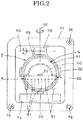
FIG. 2] FIG. 2 is a schematic front view (a view from the arrow II inFIG. 1 ) showing a lamp unit. - [
FIG. 3] FIG. 3 is a schematic bottom view (a view taken along the arrow line III-III inFIG. 1 ) showing the lamp unit. - [
FIG. 4] FIG. 4 is a schematic bottom view (a schematic bottom view corresponding toFIG. 3 ) showing a state in which the lamp unit is rotated to the right. - Hereinafter, an embodiment (example) of a vehicular headlight according to the present invention will be described in detail with reference to the drawings. In the description, the front, rear, up, down, right, and left denote the front, rear, up, down, right, and left in a state where the vehicular headlight according to the invention is mounted on a vehicle. The drawings are schematic views in which main components are illustrated while other components are not illustrated. The dashed arrows in
FIGS. 1 ,3, and 4 indicate the air or the flow of air. - Hereinafter, the configuration of a vehicular headlight according to the present embodiment will be described. In the drawings, reference numeral 1 denotes a vehicular headlight according to the present embodiment.
- The vehicular headlights 1 are mounted on the right and left sides of the front portion of a vehicle (not shown). Each vehicular headlight 1 is a headlamp in this example. Each vehicular headlight 1 includes a
lamp housing 10, alamp lens 11, alamp unit 2, afan 3, and a lightsource drive circuit 4 as shown inFIG. 1 . - The lamp housing 10 and the lamp lens (e.g., a transparent outer lens) 11 form a
lamp chamber 12. Thelamp unit 2, thefan 3, and the lightsource drive circuit 4 are disposed in thelamp chamber 12. While components other than thelamp unit 2 are not shown in thelamp chamber 12 in the drawing, an ADB irradiation lamp unit, a fog lamp, a cornering lamp, a clearance lamp, a turn signal lamp, an overhead sign lamp, a daytime running lamp, or the like may be disposed therein. - The
lamp unit 2 is a projector type lamp unit in this example. Thelamp unit 2 includes alight source 20, aheat sink 5, and alight control member 6. Thelamp unit 2 emits at least one of an unillustrated low beam light distribution pattern (passing light distribution pattern) and an unillustrated high beam light distribution pattern (driving light distribution pattern) along an optical axis Z to transmit the light distribution pattern(s) through thelamp lens 11, and irradiates an area in front of the vehicle with the light distribution pattern(s). Thelamp unit 2 is attached to thelamp housing 10 via an optical axis adjustment mechanism (an aiming mechanism and a swivel mechanism) 7. - The
light source 20 is a semiconductor type light source in this example, and a self-emitting semiconductor type light source such as an LED, an OEL, or an OLED (organic EL) is used. Thelight source 20 is driven by the operation of the lightsource drive circuit 4; that is, thelight source 20 emits light. Thelight source 20 generates heat when emitting light. - The
heat sink 5 includes amounting portion 50 and a plurality ofheat radiating portions 51. Themounting portion 50 has a plate shape and is disposed parallel or approximately parallel to the optical axis Z of thelamp unit 2, that is, is disposed horizontally or approximately horizontally, in this example. Thelight source 20 is mounted at the center of a flat surface (upper surface) of themounting portion 50. The plurality ofheat radiating portions 51 is provided integrally on a bottom surface (lower surface) of themounting portion 50, the bottom surface being opposite to thelight source 20, so as to be vertical or approximately vertical to the optical axis Z of thelamp unit 2. That is, theheat radiating portions 51 project downward from themounting portion 50. The plurality ofheat radiating portions 51 faces an outlet on an outlet side of thefan 3. - In this example, the
heat radiating portions 51, each of which has an approximately cylindrical shape, are arranged in a staggered manner (arranged alternately). With this configuration, the plurality ofheat radiating portions 51 has no directivity in the direction of the air flow (the blown air direction) from thefan 3 used for heat radiation of thelight source 20. Concerning the vertical lengths of theheat radiating portions 51, theheat radiating portion 51 at the center of themounting portion 50 at which thelight source 20 is attached is the longest while the otherheat radiating portions 51 get shorter as they get closer to the periphery of themounting portion 50. In addition, all theheat radiating portions 51 have a same or almost same horizontal cross-sectional area (diameter). Further, theheat radiating portions 51 are slightly larger in horizontal cross-sectional area at their upper end portions than at their lower end portions. A guide member to guide the air forcibly sent from thefan 3 to pass through the space among the plurality ofheat radiating portions 51 may be provided, which is not shown in the drawings. - In this example, the
light control member 6 includes areflector 60 and aprojection lens 61. Thereflector 60 is attached to a flat surface of themounting portion 50 of theheat sink 5. A reflecting surface formed of a free-form surface based on an ellipsoid of revolution (elliptic) is provided on the inner surface of thereflector 60. The reflecting surface has two focal points and an optical axis. Thelight source 20 is disposed at or near one of the focal points. - The
projection lens 61 is attached to the mountingportion 50 of theheat sink 5 via aholder 62. Theprojection lens 61 includes a lens made of resin or a lens made of glass. Theprojection lens 61 has a rear focal point (a meridional image plane that is a focal plane on an object space side) and an optical axis. The rear focal point is located at or near the other focal point of the reflecting surface. The optical axis coincides with or approximately coincides with the optical axis Z of thelamp unit 2. Theprojection lens 61 faces thelamp lens 11. - Here, when the
lamp unit 2 makes a switch between the low beam light distribution pattern and the high beam light distribution pattern to emit the pattern, a movable shade (not shown) and a solenoid 63 (see the two-dot chain line inFIG. 1 ) are disposed between thereflector 60 and theprojection lens 61. The movable shade is moved by the operation of thesolenoid 63 to make the switch between the low beam light distribution pattern and the high beam light distribution pattern. In addition, when thelamp unit 2 emits the low beam light distribution pattern, a fixed shade (not shown) is disposed between thereflector 60 and theprojection lens 61. The movable shade, thesolenoid 63, and the fixed shade are attached to theholder 62, theheat sink 5, or the like, and together with thereflector 60 and theprojection lens 61, constitute thelight control member 6. The lower portion of theprojection lens 61 of thelight control member 6 and thesolenoid 63 face the outlet side (the outlet 34) of thefan 3 through theheat radiating portions 51 of theheat sink 5. - The optical
axis adjustment mechanism 7 includes asupport mechanism 70, afirst bracket 71, asecond bracket 72, aswivel mechanism 73, a vertical-direction opticalaxis adjustment mechanism 74, a horizontal-direction opticalaxis adjustment mechanism 75, and apivot mechanism 76. - The
first bracket 71 is attached to thelamp housing 10 via the vertical-direction opticalaxis adjustment mechanism 74, the horizontal-direction opticalaxis adjustment mechanism 75, and thepivot mechanism 76. Thesecond bracket 72 is attached to thefirst bracket 71 via thesupport mechanism 70. Thelamp unit 2 is attached to thesecond bracket 72. Theswivel mechanism 73 is attached to thefirst bracket 71. Adrive shaft 77 of theswivel mechanism 73 is attached to thesecond bracket 72. - Rotationally manipulating an adjusting screw of the vertical-direction optical
axis adjustment mechanism 74 with the use of the opticalaxis adjustment mechanism 7 allows thelamp unit 2 as well as thesupport mechanism 70, thefirst bracket 71, thesecond bracket 72, and theswivel mechanism 73 to be moved around the horizontal axis connecting the rotation center of the horizontal-direction opticalaxis adjustment mechanism 75 and the rotation center of thepivot mechanism 76 to move the optical axis Z in the vertical direction with respect to thelamp housing 10. In addition, rotationally manipulating an adjusting screw of the horizontal-direction opticalaxis adjustment mechanism 75 allows thelamp unit 2 as well as thesupport mechanism 70, thefirst bracket 71, thesecond bracket 72, and theswivel mechanism 73 to be moved around the vertical axis connecting the rotation center of the vertical-direction opticalaxis adjustment mechanism 74 and the rotation center of thepivot mechanism 76 to move the optical axis Z in the horizontal direction with respect to thelamp housing 10. These adjustments of the optical axis Z of thelamp unit 2 are made in operations performed before shipment or during maintenance. - Meanwhile, rotating the
drive shaft 77 of theswivel mechanism 73 about a vertical axis O1 passing through the rotation center of thesupport mechanism 70 allows thelamp unit 2 to be rotated (swiveled) in the vertical direction about the vertical axis O1 with respect to thefirst bracket 71 as well as thesecond bracket 72. Thelamp unit 2 shown inFIG. 4 is in the state of being rotated in the right direction about the vertical axis O1 with respect to thelamp unit 2 shown inFIG. 3 . SinceFIGS. 3 and 4 are schematic bottom views, the lower sides of the drawings are the right sides at the time when the vehicular headlights 1 are mounted on the right and left sides of the front portion of the vehicle. In addition, moving thedrive shaft 77 of theswivel mechanism 73 in the forward direction F or the backward direction B (seeFIG. 1 ) allows thelamp unit 2 to be rotated in the vertical direction about a horizontal axis O2 passing through the rotation center of thesupport mechanism 70 with respect to thefirst bracket 71 as well as thesecond bracket 72. These orientation changes of the optical axis Z of thelamp unit 2 are automatically made by an automatic optical axis control system according to the running conditions of the vehicle. - The
fan 3 is attached to the back side of the lamp housing 10 (the opposite side to the lamp lens 11) separately from thelamp unit 2 as shown inFIGS. 1 ,3, and 4 . Thefan 3 is of an axial flow type that takes in the air from the axial rear side and lets out the air to the axial front side. The axial direction of thefan 3 and the optical axis Z of thelamp unit 2 are parallel or approximately parallel to each other. The outlet side on the front side of thefan 3 faces theheat radiating portions 51 of theheat sink 5. The intake side on the rear side of thefan 3 faces the lightsource drive circuit 4. - The
fan 3 includes a motor (not shown), animpeller 30 rotated by the motor,blades 31 provided to theimpeller 30, and acasing 32 covering the motor, theimpeller 30, and theblades 31. Thecasing 32 has a hollow cylindrical shape of which the front end and the rear end are open. The rear end of thecasing 32 is attached to thelamp housing 10. A motor is attached to the front end of thecasing 32 via a mounting arm. - An
inlet 33 is provided to a side plate of thecasing 32 at a position on the rear side of theblades 31. The range from theinlet 33 to the rear side of theblades 31 defines an inlet side of thefan 3. Anoutlet 34 is provided to the front end of thecasing 32. Theoutlet 34 defines an outlet side of thefan 3. - The light
source drive circuit 4, together with thefan 3, is attached to thelamp housing 10 separately from thelamp unit 2 as shown inFIGS. 1 ,3, and 4 . The lightsource drive circuit 4 drives thelight source 20, and adjusts the output according to the heat generation of thelight source 20. The lightsource drive circuit 4 may have the function of controlling the driving of thefan 3. - The light
source drive circuit 4 includes acasing 40, asubstrate 41, and a heatconductive medium 42. Thecasing 40 is housed in thecasing 32 of thefan 3, and is attached to the rear side of the lamp housing 10 (the opposite side to the lamp lens 11). Thesubstrate 41 is housed in thecasing 40.Electronic components 43 are mounted on one surface (rear surface) of thesubstrate 41. A portion of thecasing 40, the portion being on the inlet side of thefan 3, (a portion on the front side) and the surface of thesubstrate 41 opposite to the electronic components 43 (the front surface) are tightly fixed to each other via a heat conductive medium (e.g., a heat conductive adhesive, a grease, and a heat conductive grease) 42. - The vehicular headlight 1 according to the present embodiment is configured as described above, and the operation thereof will be described below.
- The
light source 20 is lit to emit light. Then, the light emitted from thelight source 20 is reflected by the reflecting surface of thereflector 60 toward theprojection lens 61. The reflected light is transmitted through theprojection lens 61 and thelamp lens 11 to emit at least one of the low beam light distribution pattern and the high beam light distribution pattern, and irradiates an area in front of the vehicle with the light distribution pattern(s). Here, the heat generated in thelight source 20 is conducted to the plurality ofheat radiating portions 51 via the mountingportion 50 of theheat sink 5. In addition, the heat generated in theelectronic components 43 of the lightsource drive circuit 4 is conducted to the portion of thecasing 40 on the inlet side of thefan 3 via thesubstrate 41 and the heatconductive medium 42. - Meanwhile, when the motor of the
fan 3 is driven, theimpeller 30 and theblades 31 are rotated. Thus, the air is forced to flow. That is, the air is forcibly taken in from theinlet 33 of thecasing 32 in a direction vertical or approximately vertical to the axial direction of thefan 3, and is made to forcibly flow from the inlet side to the outlet side in the axial direction of thefan 3 in thecasing 32. At this time, because the air passes through the portion of thecasing 40 of the lightsource drive circuit 4 on the inlet side portion of thefan 3, the heat generated in theelectronic components 43 of the lightsource drive circuit 4 is efficiently cooled through thesubstrate 41, the heatconductive medium 42, and thecasing 40. - In addition, the air forcibly made to flow in the axial direction of the
fan 3 is forcibly let out from theoutlet 34 of thecasing 32 toward theheat radiating portions 51 of theheat sink 5. At this time, since the air passes through the space among the plurality ofheat radiating portions 51 of theheat sink 5 from the side of thefan 3 toward theprojection lens 61, the heat generated in thelight source 20 is efficiently cooled through the mountingportion 50 and the plurality ofheat radiating portions 51 of theheat sink 5. - Here, having a columnar shape, the
heat radiating portions 51 of theheat sink 5 have no directivity in the direction of the air flow (the blown air direction) from thefan 3 used for heat radiation of thelight source 20 as compared with heat radiating portions having a fin shape (a plate shape). Thus, when the orientation of the optical axis Z of thelamp unit 2 is adjusted and changed, for example, even when the optical axis Z of thelamp unit 2 is oriented forward as shown inFIG. 3 or even when oriented to the right as shown inFIG. 4 , the air is made to forcibly flow smoothly without stagnation through the space among the plurality of columnar-shapedheat radiating portions 51. - Further, the air made to forcibly flow from the side of the
fan 3 toward theprojection lens 61 through the space among the plurality ofheat radiating portions 51 of theheat sink 5 passes through to cool thesolenoid 63, and hits the lower portion of theprojection lens 61 along the incident surface of theprojection lens 61 to cool theprojection lens 61. The air that has cooled thesolenoid 63 and theprojection lens 61 is cooled while circulating in thelamp chamber 12, and forcibly let in again from theinlet 33 of thecasing 32 to be let out from theoutlet 34 of thecasing 32 by using thefan 3. - The vehicular headlight 1 according to the present embodiment has the above-described configuration and operation, and the effects thereof will be described below.
- In the vehicular headlight 1 according to the present embodiment, the outlet side of the
fan 3 faces the plurality ofheat radiating portions 51 of theheat sink 5, and the inlet side of thefan 3 faces thecasing 40 of the lightsource drive circuit 4. As a result of this, the vehicular headlight 1 according to the present embodiment can efficiently cool thelight source 20 through the plurality ofheat radiating portions 51 of theheat sink 5 by using thefan 3, and also can efficiently cool the lightsource drive circuit 4 through thecasing 40 by using thefan 3. - Since the vehicular headlight 1 according to the present embodiment can efficiently cool the
light source 20 through the plurality ofheat radiating portions 51 of theheat sink 5 by using thefan 3, and also can efficiently cool the lightsource drive circuit 4 through thecasing 40 by using thefan 3, theheat sink 5 and the lightsource drive circuit 4 can be reduced in size. - Since the vehicular headlight 1 according to the present embodiment has the
fan 3 and the lightsource drive circuit 4 attached to thelamp housing 10 separately from thelamp unit 2, thelamp unit 2 can be reduced in size and weight. Thus, in the vehicular headlight 1 according to the present embodiment, the opticalaxis adjustment mechanism 7 can have optimized torque and structural strength, which allows a power portion of the opticalaxis adjustment mechanism 7 to be reduced in size and a structural portion of the opticalaxis adjustment mechanism 7 to be reduced in weight. - In the vehicular headlight 1 according to the present embodiment, the
heat sink 5 includes the mountingportion 50 to which thelight source 20 is attached, and the plurality ofheat radiating portions 51 having a columnar shape, provided on the opposite side of the mountingportion 50 to thelight source 20, and facing the outlet side of thefan 3. As a result of this, in the vehicular headlight 1 according to the present embodiment, theheat radiating portions 51 have no directivity in the direction of the air flow (the blown air direction) from thefan 3 used for heat radiation of thelight source 20. Thus, in the vehicular headlight 1 according to the present embodiment, even when the orientation of the optical axis Z of thelamp unit 2 is adjusted and changed by rotating thelamp unit 2 in the vertical direction or the horizontal direction with the use of the opticalaxis adjustment mechanism 7 or theswivel mechanism 73, the air is made to forcibly flow smoothly without stagnation through the space among the plurality of columnar-shapedheat radiating portions 51, whereby thelight source 20 can be cooled reliably and efficiently. - In the vehicular headlight 1 according to the present embodiment, concerning the vertical lengths of the
heat radiating portions 51 of theheat sink 5, since theheat radiating portion 51 at the center of the mountingportion 50 at which thelight source 20 is attached is longer than the otherheat radiating portions 51 around the center of the mountingportion 50, the heat radiation effect of theheat radiating portion 51 at the center of the mountingportion 50 is higher than that of the otherheat radiating portions 51 around the center of the mountingportion 50. As a result of this, in the vehicular headlight 1 according to the present embodiment, thelight source 20 can be cooled further reliably and efficiently by the longerheat radiating portion 51 at the center of the mountingportion 50 having a higher heat radiation effect. In addition, in the vehicular headlight 1 according to the present embodiment, since theheat radiating portions 51 of theheat sink 5 are arranged in a staggered manner, the air is made to forcibly flow smoothly without stagnation through the space among the plurality of columnar-shapedheat radiating portions 51, whereby thelight source 20 can be cooled further reliably and efficiently. - In the vehicular headlight 1 according to the present embodiment, the light
source drive circuit 4 includes thecasing 40 attached to thelamp housing 10, thesubstrate 41 on which theelectronic components 43 are mounted, and the heatconductive medium 42 via which the portion of thecasing 40 on the inlet side of thefan 3 and thesubstrate 41 are tightly fixed to each other. As a result of this, in the vehicular headlight 1 according to the present embodiment, the lightsource drive circuit 4 can be cooled reliably and efficiently. - In the vehicular headlight 1 according to the present embodiment, the lower portion of the
projection lens 61 of thelight control member 6 and thesolenoid 63 face the outlet side (the outlet 34) of thefan 3 through theheat radiating portions 51 of theheat sink 5. As a result of this, in the vehicular headlight 1 according to the present embodiment, theprojection lens 61 of thelight control member 6 and thesolenoid 63 can also be cooled reliably and efficiently. - In the above embodiment, all the
heat radiating portions 51 of theheat sink 5 have a same or almost same horizontal cross-sectional area (diameter). However, it is also possible in the present invention that theheat radiating portion 51 at the center of the mountingportion 50 at which thelight source 20 is attached is larger in horizontal cross-sectional area while the otherheat radiating portions 51 get smaller in horizontal cross-sectional area as they get closer to the periphery of the mountingportion 50, which is not shown in the drawings. In this case, the heat radiation effect of theheat radiating portion 51 at the center of the mountingportion 50 is higher than that of the otherheat radiating portions 51 around the center of the mountingportion 50, whereby thelight source 20 can be cooled further reliably and efficiently. Furthermore, in addition to making theheat radiating portion 51 at the center of the mountingportion 50 larger in horizontal cross-sectional area than the otherheat radiating portions 51 around the center of the mountingportion 50, making theheat radiating portion 51 at the center of the mountingportion 50 vertically longer than the otherheat radiating portions 51 around the center of the mountingportion 50 allows thelight source 20 to be cooled further reliably and efficiently. - While the
heat radiating portions 51 are slightly larger in horizontal cross-sectional area at their upper end portions than at their lower end portions in the above embodiment, it is also possible in the present invention that theheat radiating portions 51 of theheat sink 5 are uniform or almost uniform in horizontal cross-sectional area from their upper end portions to their lower end portions, which is not shown in the drawings. - The present invention is not limited by the embodiments described above.
-
- 1 vehicular headlight
- 10 lamp housing
- 11 lamp lens
- 12 lamp chamber
- 2 lamp unit
- 20 light source
- 3 fan
- 30 impeller
- 31 blade
- 32 casing
- 33 inlet
- 34 outlet
- 4 light source drive circuit
- 40 casing
- 41 substrate
- 42 heat conductive medium
- 43 electronic component
- 5 heat sink
- 50 mounting portion
- 51 heat radiating portion
- 6 light control member
- 60 reflector
- 61 projection lens
- 62 holder
- 63 solenoid
- 7 optical axis adjustment mechanism
- 70 support mechanism
- 71 first bracket
- 72 second bracket
- 73 swivel mechanism
- 74 vertical-direction optical axis adjustment mechanism
- 75 horizontal-direction optical axis adjustment mechanism
- 76 pivot mechanism
- 77 drive shaft
- B backward direction
- F forward direction
- O1 vertical axis
- O2 horizontal axis
- Z optical axis
Claims (4)
- A vehicular headlight comprising:a lamp housing and a lamp lens that form a lamp chamber;a lamp unit disposed in the lamp chamber and attached to the lamp housing via an optical axis adjustment mechanism; anda fan and a light source drive circuit disposed in the lamp chamber and attached to the lamp housing separately from the lamp unit,wherein the lamp unit includes a light source driven by the light source drive circuit, a heat sink, and a light control member arranged to control light from the light source, andan outlet side of the fan faces the heat sink, and an intake side of the fan faces the light source drive circuit.
- The vehicular headlight according to claim 1, wherein the heat sink includes a mounting portion to which the light source is attached, and a plurality of heat radiating portions having a columnar shape, provided on an opposite side of the mounting portion to the light source, and facing the outlet side of the fan.
- The vehicular headlight according to claim 1, wherein the light source drive circuit includes a casing attached to the lamp housing, a substrate on which an electronic component is mounted, and a heat conductive medium with which a portion of the casing, the portion being on the intake side of the fan, and the substrate are closely fixed to each other.
- The vehicular headlight according to claim 1, wherein the light control member faces the outlet side of the fan through the heat sink.
Applications Claiming Priority (2)
| Application Number | Priority Date | Filing Date | Title |
|---|---|---|---|
| JP2017034913A JP6938958B2 (en) | 2017-02-27 | 2017-02-27 | Vehicle headlights |
| PCT/JP2018/006945 WO2018155684A1 (en) | 2017-02-27 | 2018-02-26 | Vehicular headlight |
Publications (2)
| Publication Number | Publication Date |
|---|---|
| EP3587903A1 true EP3587903A1 (en) | 2020-01-01 |
| EP3587903A4 EP3587903A4 (en) | 2020-12-16 |
Family
ID=63252813
Family Applications (1)
| Application Number | Title | Priority Date | Filing Date |
|---|---|---|---|
| EP18757708.5A Withdrawn EP3587903A4 (en) | 2017-02-27 | 2018-02-26 | VEHICLE HEADLIGHTS |
Country Status (5)
| Country | Link |
|---|---|
| US (1) | US11073270B2 (en) |
| EP (1) | EP3587903A4 (en) |
| JP (1) | JP6938958B2 (en) |
| CN (1) | CN110366656A (en) |
| WO (1) | WO2018155684A1 (en) |
Family Cites Families (13)
| Publication number | Priority date | Publication date | Assignee | Title |
|---|---|---|---|---|
| JP5248183B2 (en) | 2008-04-22 | 2013-07-31 | 株式会社小糸製作所 | Vehicle lighting |
| JP5457061B2 (en) * | 2009-04-01 | 2014-04-02 | 株式会社小糸製作所 | Vehicle headlamp |
| JP2010262903A (en) | 2009-05-11 | 2010-11-18 | Koito Mfg Co Ltd | Vehicle lighting |
| JP2011048923A (en) * | 2009-08-25 | 2011-03-10 | Stanley Electric Co Ltd | Lighting fixture for vehicle |
| JP2011258411A (en) * | 2010-06-09 | 2011-12-22 | Koito Mfg Co Ltd | Vehicular lamp |
| US8203274B2 (en) * | 2010-08-13 | 2012-06-19 | De Castro Erwin L | LED and thermal management module for a vehicle headlamp |
| JP5597500B2 (en) * | 2010-09-28 | 2014-10-01 | 株式会社小糸製作所 | Light emitting module and vehicle lamp |
| JP2012174539A (en) * | 2011-02-22 | 2012-09-10 | Ichikoh Ind Ltd | Vehicular headlight |
| JP6061638B2 (en) * | 2012-11-20 | 2017-01-18 | 株式会社小糸製作所 | Vehicle lighting |
| JP2014120344A (en) * | 2012-12-17 | 2014-06-30 | Ichikoh Ind Ltd | Vehicle lighting tool |
| JP6345052B2 (en) * | 2013-12-20 | 2018-06-20 | 株式会社小糸製作所 | Vehicle headlamp |
| JP6520003B2 (en) * | 2014-07-25 | 2019-05-29 | 市光工業株式会社 | Vehicle lamp |
| JP6375801B2 (en) * | 2014-09-09 | 2018-08-22 | 株式会社デンソー | Light emitting device for vehicle |
-
2017
- 2017-02-27 JP JP2017034913A patent/JP6938958B2/en active Active
-
2018
- 2018-02-26 EP EP18757708.5A patent/EP3587903A4/en not_active Withdrawn
- 2018-02-26 CN CN201880013995.1A patent/CN110366656A/en not_active Withdrawn
- 2018-02-26 US US16/488,672 patent/US11073270B2/en not_active Expired - Fee Related
- 2018-02-26 WO PCT/JP2018/006945 patent/WO2018155684A1/en not_active Ceased
Also Published As
| Publication number | Publication date |
|---|---|
| JP6938958B2 (en) | 2021-09-22 |
| US20190376679A1 (en) | 2019-12-12 |
| CN110366656A (en) | 2019-10-22 |
| EP3587903A4 (en) | 2020-12-16 |
| WO2018155684A1 (en) | 2018-08-30 |
| JP2018142423A (en) | 2018-09-13 |
| US11073270B2 (en) | 2021-07-27 |
Similar Documents
| Publication | Publication Date | Title |
|---|---|---|
| US8398279B2 (en) | Headlamp apparatus for vehicle | |
| JP5457061B2 (en) | Vehicle headlamp | |
| US7896512B2 (en) | Vehicle headlamp | |
| KR102129671B1 (en) | Vehicle headlamp | |
| JP4565646B2 (en) | LED light source vehicle lamp | |
| JPWO2015122303A1 (en) | Optical unit and vehicle lamp | |
| JP5806053B2 (en) | Vehicle headlamp | |
| CN102878509B (en) | Headlight for automobile | |
| EP2543927A2 (en) | Vehicle headlamp | |
| JP6680537B2 (en) | Optical unit and vehicle lamp | |
| JP6651797B2 (en) | Vehicle headlights | |
| CN106152007B (en) | lights for vehicles | |
| CN104235722A (en) | Lamp unit and vehicle lamp | |
| JP6645018B2 (en) | Vehicle headlights | |
| JP2017228417A (en) | Defogging structure of vehicle head lamp | |
| US11073270B2 (en) | Vehicular headlight | |
| US10746371B2 (en) | Vehicular lamp | |
| KR101606841B1 (en) | LED headlight | |
| JP2014063603A (en) | Vehicular headlamp | |
| JP6439341B2 (en) | Vehicle lighting | |
| JP7146468B2 (en) | vehicle headlight | |
| JP2015230890A (en) | Automotive lighting device and automobile equipped with the same |
Legal Events
| Date | Code | Title | Description |
|---|---|---|---|
| STAA | Information on the status of an ep patent application or granted ep patent |
Free format text: STATUS: THE INTERNATIONAL PUBLICATION HAS BEEN MADE |
|
| PUAI | Public reference made under article 153(3) epc to a published international application that has entered the european phase |
Free format text: ORIGINAL CODE: 0009012 |
|
| STAA | Information on the status of an ep patent application or granted ep patent |
Free format text: STATUS: REQUEST FOR EXAMINATION WAS MADE |
|
| 17P | Request for examination filed |
Effective date: 20190827 |
|
| AK | Designated contracting states |
Kind code of ref document: A1 Designated state(s): AL AT BE BG CH CY CZ DE DK EE ES FI FR GB GR HR HU IE IS IT LI LT LU LV MC MK MT NL NO PL PT RO RS SE SI SK SM TR |
|
| AX | Request for extension of the european patent |
Extension state: BA ME |
|
| DAV | Request for validation of the european patent (deleted) | ||
| DAX | Request for extension of the european patent (deleted) | ||
| A4 | Supplementary search report drawn up and despatched |
Effective date: 20201118 |
|
| RIC1 | Information provided on ipc code assigned before grant |
Ipc: F21Y 115/10 20160101ALI20201112BHEP Ipc: F21S 41/00 20180101AFI20201112BHEP Ipc: F21S 41/147 20180101ALI20201112BHEP Ipc: F21W 103/00 20180101ALI20201112BHEP Ipc: F21V 29/67 20150101ALI20201112BHEP Ipc: F21Y 115/15 20160101ALI20201112BHEP Ipc: F21V 29/508 20150101ALI20201112BHEP Ipc: F21V 29/503 20150101ALI20201112BHEP Ipc: F21W 104/00 20180101ALI20201112BHEP Ipc: F21S 43/00 20180101ALI20201112BHEP Ipc: F21S 45/43 20180101ALI20201112BHEP Ipc: F21S 45/00 20180101ALI20201112BHEP Ipc: F21W 102/00 20180101ALI20201112BHEP Ipc: F21S 41/657 20180101ALI20201112BHEP Ipc: F21W 105/00 20180101ALI20201112BHEP |
|
| STAA | Information on the status of an ep patent application or granted ep patent |
Free format text: STATUS: THE APPLICATION IS DEEMED TO BE WITHDRAWN |
|
| 18D | Application deemed to be withdrawn |
Effective date: 20210619 |