EP3587793A1 - Magnetisches zahnstangenkupplungssystem und meereswellenenergieumwandlungssystem - Google Patents
Magnetisches zahnstangenkupplungssystem und meereswellenenergieumwandlungssystem Download PDFInfo
- Publication number
- EP3587793A1 EP3587793A1 EP18180948.4A EP18180948A EP3587793A1 EP 3587793 A1 EP3587793 A1 EP 3587793A1 EP 18180948 A EP18180948 A EP 18180948A EP 3587793 A1 EP3587793 A1 EP 3587793A1
- Authority
- EP
- European Patent Office
- Prior art keywords
- pinion
- magnetic
- rack
- coupling system
- pattern
- Prior art date
- Legal status (The legal status is an assumption and is not a legal conclusion. Google has not performed a legal analysis and makes no representation as to the accuracy of the status listed.)
- Withdrawn
Links
- 230000005291 magnetic effect Effects 0.000 title claims abstract description 131
- 230000008878 coupling Effects 0.000 title claims abstract description 63
- 238000010168 coupling process Methods 0.000 title claims abstract description 63
- 238000005859 coupling reaction Methods 0.000 title claims abstract description 63
- 238000006243 chemical reaction Methods 0.000 title claims description 25
- 230000005294 ferromagnetic effect Effects 0.000 claims abstract description 58
- 230000003252 repetitive effect Effects 0.000 claims abstract description 9
- 239000013535 sea water Substances 0.000 claims description 7
- 239000011241 protective layer Substances 0.000 claims description 2
- 230000004907 flux Effects 0.000 description 7
- 239000003302 ferromagnetic material Substances 0.000 description 6
- 238000012423 maintenance Methods 0.000 description 4
- 238000012986 modification Methods 0.000 description 3
- 230000004048 modification Effects 0.000 description 3
- 238000004544 sputter deposition Methods 0.000 description 3
- XEEYBQQBJWHFJM-UHFFFAOYSA-N Iron Chemical compound [Fe] XEEYBQQBJWHFJM-UHFFFAOYSA-N 0.000 description 2
- 238000006073 displacement reaction Methods 0.000 description 2
- 239000010410 layer Substances 0.000 description 2
- 239000000463 material Substances 0.000 description 2
- 238000000034 method Methods 0.000 description 2
- 238000006467 substitution reaction Methods 0.000 description 2
- 230000006978 adaptation Effects 0.000 description 1
- 230000002411 adverse Effects 0.000 description 1
- 239000011248 coating agent Substances 0.000 description 1
- 238000000576 coating method Methods 0.000 description 1
- 230000007797 corrosion Effects 0.000 description 1
- 238000005260 corrosion Methods 0.000 description 1
- 230000000694 effects Effects 0.000 description 1
- 229910052742 iron Inorganic materials 0.000 description 1
- 229910001220 stainless steel Inorganic materials 0.000 description 1
- 239000010935 stainless steel Substances 0.000 description 1
- XLYOFNOQVPJJNP-UHFFFAOYSA-N water Substances O XLYOFNOQVPJJNP-UHFFFAOYSA-N 0.000 description 1
Images


Classifications
-
- H—ELECTRICITY
- H02—GENERATION; CONVERSION OR DISTRIBUTION OF ELECTRIC POWER
- H02K—DYNAMO-ELECTRIC MACHINES
- H02K49/00—Dynamo-electric clutches; Dynamo-electric brakes
- H02K49/10—Dynamo-electric clutches; Dynamo-electric brakes of the permanent-magnet type
- H02K49/104—Magnetic couplings consisting of only two coaxial rotary elements, i.e. the driving element and the driven element
- H02K49/108—Magnetic couplings consisting of only two coaxial rotary elements, i.e. the driving element and the driven element with an axial air gap
-
- F—MECHANICAL ENGINEERING; LIGHTING; HEATING; WEAPONS; BLASTING
- F03—MACHINES OR ENGINES FOR LIQUIDS; WIND, SPRING, OR WEIGHT MOTORS; PRODUCING MECHANICAL POWER OR A REACTIVE PROPULSIVE THRUST, NOT OTHERWISE PROVIDED FOR
- F03B—MACHINES OR ENGINES FOR LIQUIDS
- F03B13/00—Adaptations of machines or engines for special use; Combinations of machines or engines with driving or driven apparatus; Power stations or aggregates
- F03B13/12—Adaptations of machines or engines for special use; Combinations of machines or engines with driving or driven apparatus; Power stations or aggregates characterised by using wave or tide energy
- F03B13/14—Adaptations of machines or engines for special use; Combinations of machines or engines with driving or driven apparatus; Power stations or aggregates characterised by using wave or tide energy using wave energy
- F03B13/16—Adaptations of machines or engines for special use; Combinations of machines or engines with driving or driven apparatus; Power stations or aggregates characterised by using wave or tide energy using wave energy using the relative movement between a wave-operated member, i.e. a "wom" and another member, i.e. a reaction member or "rem"
- F03B13/18—Adaptations of machines or engines for special use; Combinations of machines or engines with driving or driven apparatus; Power stations or aggregates characterised by using wave or tide energy using wave energy using the relative movement between a wave-operated member, i.e. a "wom" and another member, i.e. a reaction member or "rem" where the other member, i.e. rem is fixed, at least at one point, with respect to the sea bed or shore
- F03B13/1845—Adaptations of machines or engines for special use; Combinations of machines or engines with driving or driven apparatus; Power stations or aggregates characterised by using wave or tide energy using wave energy using the relative movement between a wave-operated member, i.e. a "wom" and another member, i.e. a reaction member or "rem" where the other member, i.e. rem is fixed, at least at one point, with respect to the sea bed or shore and the wom slides relative to the rem
- F03B13/1855—Adaptations of machines or engines for special use; Combinations of machines or engines with driving or driven apparatus; Power stations or aggregates characterised by using wave or tide energy using wave energy using the relative movement between a wave-operated member, i.e. a "wom" and another member, i.e. a reaction member or "rem" where the other member, i.e. rem is fixed, at least at one point, with respect to the sea bed or shore and the wom slides relative to the rem where the connection between wom and conversion system takes tension and compression
- F03B13/186—Adaptations of machines or engines for special use; Combinations of machines or engines with driving or driven apparatus; Power stations or aggregates characterised by using wave or tide energy using wave energy using the relative movement between a wave-operated member, i.e. a "wom" and another member, i.e. a reaction member or "rem" where the other member, i.e. rem is fixed, at least at one point, with respect to the sea bed or shore and the wom slides relative to the rem where the connection between wom and conversion system takes tension and compression the connection being of the rack-and-pinion type
-
- F—MECHANICAL ENGINEERING; LIGHTING; HEATING; WEAPONS; BLASTING
- F03—MACHINES OR ENGINES FOR LIQUIDS; WIND, SPRING, OR WEIGHT MOTORS; PRODUCING MECHANICAL POWER OR A REACTIVE PROPULSIVE THRUST, NOT OTHERWISE PROVIDED FOR
- F03B—MACHINES OR ENGINES FOR LIQUIDS
- F03B13/00—Adaptations of machines or engines for special use; Combinations of machines or engines with driving or driven apparatus; Power stations or aggregates
- F03B13/12—Adaptations of machines or engines for special use; Combinations of machines or engines with driving or driven apparatus; Power stations or aggregates characterised by using wave or tide energy
- F03B13/14—Adaptations of machines or engines for special use; Combinations of machines or engines with driving or driven apparatus; Power stations or aggregates characterised by using wave or tide energy using wave energy
- F03B13/16—Adaptations of machines or engines for special use; Combinations of machines or engines with driving or driven apparatus; Power stations or aggregates characterised by using wave or tide energy using wave energy using the relative movement between a wave-operated member, i.e. a "wom" and another member, i.e. a reaction member or "rem"
- F03B13/18—Adaptations of machines or engines for special use; Combinations of machines or engines with driving or driven apparatus; Power stations or aggregates characterised by using wave or tide energy using wave energy using the relative movement between a wave-operated member, i.e. a "wom" and another member, i.e. a reaction member or "rem" where the other member, i.e. rem is fixed, at least at one point, with respect to the sea bed or shore
-
- H—ELECTRICITY
- H02—GENERATION; CONVERSION OR DISTRIBUTION OF ELECTRIC POWER
- H02K—DYNAMO-ELECTRIC MACHINES
- H02K49/00—Dynamo-electric clutches; Dynamo-electric brakes
- H02K49/10—Dynamo-electric clutches; Dynamo-electric brakes of the permanent-magnet type
- H02K49/102—Magnetic gearings, i.e. assembly of gears, linear or rotary, by which motion is magnetically transferred without physical contact
-
- H—ELECTRICITY
- H02—GENERATION; CONVERSION OR DISTRIBUTION OF ELECTRIC POWER
- H02K—DYNAMO-ELECTRIC MACHINES
- H02K7/00—Arrangements for handling mechanical energy structurally associated with dynamo-electric machines, e.g. structural association with mechanical driving motors or auxiliary dynamo-electric machines
- H02K7/06—Means for converting reciprocating motion into rotary motion or vice versa
-
- H—ELECTRICITY
- H02—GENERATION; CONVERSION OR DISTRIBUTION OF ELECTRIC POWER
- H02K—DYNAMO-ELECTRIC MACHINES
- H02K7/00—Arrangements for handling mechanical energy structurally associated with dynamo-electric machines, e.g. structural association with mechanical driving motors or auxiliary dynamo-electric machines
- H02K7/18—Structural association of electric generators with mechanical driving motors, e.g. with turbines
- H02K7/1807—Rotary generators
- H02K7/1853—Rotary generators driven by intermittent forces
-
- Y—GENERAL TAGGING OF NEW TECHNOLOGICAL DEVELOPMENTS; GENERAL TAGGING OF CROSS-SECTIONAL TECHNOLOGIES SPANNING OVER SEVERAL SECTIONS OF THE IPC; TECHNICAL SUBJECTS COVERED BY FORMER USPC CROSS-REFERENCE ART COLLECTIONS [XRACs] AND DIGESTS
- Y02—TECHNOLOGIES OR APPLICATIONS FOR MITIGATION OR ADAPTATION AGAINST CLIMATE CHANGE
- Y02E—REDUCTION OF GREENHOUSE GAS [GHG] EMISSIONS, RELATED TO ENERGY GENERATION, TRANSMISSION OR DISTRIBUTION
- Y02E10/00—Energy generation through renewable energy sources
- Y02E10/30—Energy from the sea, e.g. using wave energy or salinity gradient
Definitions
- the present disclosure is directed to a magnetic rack-and-pinion coupling system for contactless transfer of kinetic energy, and a sea wave energy conversion system with such a magnetic rack-and-pinion coupling system.
- WO 2010/130821 A2 describes a mechanical rack-and-pinion coupling system in a sea wave energy conversion system.
- the mechanical rack-and-pinion coupling system is used to transfer kinetic energy between a linear motion and a rotational motion.
- a toothed gear as a pinion of a mechanical rack-and-pinion coupling system positively engages with corresponding teeth of the rack so that a linear motion of the rack exerts a torque on the pinion.
- the mechanical rack-and-pinion coupling system is, however, inherently susceptible to wear and frictional losses. In particular, the adverse conditions in sea water require regular maintenance. Furthermore, the mechanical rack-and-pinion coupling system does not allow for slippage if the highly varying heaving forces of the sea waves exceed a certain threshold above which the structural integrity of the mechanical rack-and-pinion coupling system may be at risk.
- embodiments of the present disclosure provide a contactless transfer of kinetic energy that is less susceptible to wear and frictional loss; and requires less maintenance.
- the principle idea underlying the present disclosure for achieving this is to apply a magnetic rack-and-pinion coupling system for contactless transfer of kinetic energy in a sea wave energy conversion system, wherein the magnetic rack-and-pinion coupling system provides a sufficient torque transfer.
- a magnetic rack-and-pinion coupling system for contactless transfer of kinetic energy comprising:
- Such a magnetic rack-and-pinion coupling system may be used for any kind of contactless transfer of kinetic energy, not only for sea wave energy conversion. However, it is particularly useful for sea wave energy conversion, because the heaving forces of sea waves vary highly and may exceed a certain threshold above which the structural integrity of a mechanical coupling would be at risk.
- the magnetic rack-and-pinion coupling system according to the present disclosure allows for slippage without introducing any damage or wear to the system.
- the rack component and/or the pinion stack component can be separately encapsulated to be protected from the corrosive environment of sea water so that less maintenance is needed.
- the stack arrangement of the magnetic disc sandwiched between two pinion discs having a pattern of ferromagnetic structure along the circumference provides for a sufficient torque transfer, because the magnetic flux depends on the position of the two repetitive patterns of ferromagnetic structure relative to each other. Thereby, a motion of the rack component and/or the pinion stack component relative to each other along the linear axis exerts a torque on the pinion stack component to rotate about the rotor axis.
- the pinion stack component may be driven by a motor to rotate and thereby exerts a driving torque on the rack component for linear displacement of the rack component.
- the magnetic rack-and-pinion coupling system may be used to convert linear kinematic energy to rotational kinematic energy and/or vice versa.
- linear shall include almost-linear motion, e.g. along an arc with a radius much larger than the diameter of the pinion stack component.
- the pinion stack component may comprise a stack of N ⁇ 3 pinion discs and N-1 magnetic discs, wherein each magnetic disc is sandwiched between two neighbouring pinion discs.
- the transferable maximum torque increases with the number N-1 of magnetic discs.
- 10 pinion discs may be used with 9 magnetic discs stacked in-between.
- Those pinion discs between two neighbouring magnetic discs are more effectively used to transfer magnetic flux than the two pinion discs at the axial ends of the stack. Therefore, the two pinion discs at the axial ends of the stack may have a smaller axial width, e.g. half the width of the other pinion discs.
- all pinion discs may be identical.
- all magnetic discs may be identical in shape and size.
- the magnetic discs may be arranged in such a way that the magnetic pole orientation alternates between neighbouring magnetic discs. This doubles the magnetic flux density through those pinion discs which are arranged between two neighbouring magnetic discs. Thereby, the transferable torque is significantly increased.
- the second pattern of ferromagnetic structure may be formed by teeth extending radially further than the diameter of the magnetic disc(s).
- the pinion discs may be integrally comprised of ferromagnetic material like iron, wherein the pattern is defined by the teeth similar to a mechanical gear.
- the pinion discs may comprise at least two materials one of which is ferromagnetic and forming the radially extending teeth.
- the shape of the teeth may be optimised for maximum magnetic flux between the teeth and the first pattern of ferromagnetic structure of the rack.
- the flanks of the teeth may extend radially or parallel to each other.
- the bottom land of the tooth space may be round with a single circular or oval fillet between neighbouring teeth.
- the top land of the teeth is very important for the transfer of magnetic flux. Therefore, the preferably planar top land of each tooth is preferably of essentially the same size as the root of each tooth.
- the ratio of the size of the top land of the teeth to the size of the bottom land of the tooth spaces may be in the range of 0.8 to 1.25.
- the tooth space may be filled with non-ferromagnetic material or not filled.
- the first pattern of ferromagnetic structure may be formed by a row of ferromagnetic bars extending along a lateral alignment direction and/or by a side of the rack component having a crenelated shape along the linear axis.
- the lateral alignment direction may be essentially orthogonal to the linear axis or skewed as will be explained below.
- the first pattern of ferromagnetic structure may define a first period and the second pattern of ferromagnetic structure may define a second period, wherein the ratio between the first period and the second period ranges between 0.8 and 1.25.
- the first period and the second period are essentially equal.
- the lateral width of the first pattern of ferromagnetic structure across the linear axis may essentially be the same as or larger than the axial width of the stack of pinion discs along the rotor axis.
- the longitudinal length of the first pattern of ferromagnetic structure along the linear axis may be at least twice as long as the diameter of the stack of pinion discs. This allows at least more than a half rotation of the stack of pinion discs.
- the first pattern of ferromagnetic structure may be skewed by an angle ⁇ , wherein the angle ⁇ is spanned between a lateral alignment direction of the first pattern of ferromagnetic structure and a cross axis of the rack component perpendicular to the linear axis.
- the skewed pattern may reduce a "sputtering” or “staggering” of the torque transfer. A steadier torque transfer over time may be achieved by this to the detriment of a reduced maximum torque transfer.
- two neighbouring pinion discs may have a rotational position shifted by an angle ⁇ with respect to each other.
- the angle ⁇ may be correspondingly chosen so that all pinion discs have the same phase with respect to the skewed first pattern of ferromagnetic structure of the rack component. This reduces a "sputtering” or “staggering" of the torque transfer while the undesired reduction of maximum torque transfer is minimised.
- the second pattern of ferromagnetic structure of each pinion disc may be skewed by a twist angle ⁇ about the rotor axis.
- the angle ⁇ may be correspondingly chosen to align the pinion teeth with the skewed rack structure to achieve a smooth torque transfer while reducing the negative effect of reduced maximum torque transfer introduced by the skewing.
- the system may further comprise a separating non-ferromagnetic wall structure extending along a gap between the first pattern of ferromagnetic structure and the second pattern of ferromagnetic structure.
- the wall structure may be a wall of a housing that encapsulates the rack component and/or the pinion stack component.
- the wall component may, for instance, comprise stainless steel and/or plastic.
- the wall may be chosen as thin as possible to allow a small distance between the rack component and the pinion stack component.
- the first pattern of ferromagnetic structure and/or the second pattern of ferromagnetic structure may be coated by a protective layer.
- a protective layer may be a wall structure, a coating and/or an oxidised or deposited layer. The ferromagnetic structures and/or the magnetic discs may thereby be protected against corrosion.
- a sea wave energy conversion system comprising
- the guiding structure may be configured to be anchored or fixed relative to the seabed.
- the guiding structure may be buoyant and configured to follow heaving forces of sea waves with quicker or slower compared to the buoyance body. Thereby, the sea waves drive a motion of the buoyant body relative to the fixed and/or buoyant guiding structure.
- the rack component of the at least one magnetic rack-and-pinion coupling system may be mechanically coupled or fixed to the buoyance body and the pinion stack component of the at least one magnetic rack-and-pinion coupling system may be mechanically coupled or mounted to the guiding structure.
- the sea wave energy conversion system may comprise M ⁇ 2 magnetic rack-and-pinion coupling systems, wherein the magnetic rack-and-pinion coupling systems are arranged in an M-fold rotational symmetry with respect to the linear axis.
- M magnetic rack-and-pinion coupling systems
- the guiding structure may define a tubular inner volume along the linear axis, wherein the buoyant body is arranged at least partially within the tubular inner volume and configured to follow the sea water level within the tubular inner volume.
- the tubular inner volume is open to be flooded with sea water so that there is an up- and downward movement of the sea water level within the tubular inner volume according to the sea waves.
- the tubular inner volume may have any cross-sectional shape, e.g. round, oval, squared, triangular, hexagonal or any other.
- the tubular inner volume may have a cross-sectional shape of an M-sided regular polygon, so that M magnetic rack-and-pinion coupling systems can be arranged in an M-fold rotational symmetry with one magnetic rack-and-pinion coupling system being arranged at each side of the tubular inner volume.
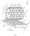
- Fig. 1 shows a magnetic rack-and-pinion coupling system 1 for contactless transfer of kinetic energy.
- the system 1 comprises a rack component 3 and a pinion stack component 5.
- the rack component 3 comprises a first pattern of ferromagnetic structure being repetitive along a linear axis L.
- the pinion stack component 5 is rotatable about a rotor axis R.
- a right-handed Cartesian coordinate system is displayed in Fig. 1 , wherein the x-axis extends along the rotor axis R and the y-axis extends along the linear axis L.
- the z-axis is the direction along which a gap 7 between the rack component 3 and the pinion stack component 5 extends.
- the rack component 3 is a single integral part made of ferromagnetic material, wherein the first pattern of ferromagnetic structure is defined by a crenelated top side forming teeth that extend like bars along a lateral alignment direction A, which extends along the x-axis in this embodiment.
- the first pattern of ferromagnetic structure defines a first period P1.
- the pinion stack component 5 comprises a stack of four identical pinion discs 9a,b,c,d each comprising a second pattern of ferromagnetic structure being repetitive along a circumference of the respective pinion disc 9a,b,c,d.
- each of the four pinion discs 9a,b,c,d is a single integral part made of ferromagnetic material, wherein the second pattern of ferromagnetic structure is formed radially extending teeth 11 like teeth of a mechanical gear.
- the second pattern of ferromagnetic structure defines a second period P2, wherein the ratio between the first period P1 and the second period P2 is essentially 1 or ranges between 0.8 and 1.25.
- the pinion stack component 5 further comprises a three magnetic discs 13a,b,c, wherein each magnetic disc 13a,b,c is sandwiched between two neighbouring pinion discs 9a,b,c,d.
- Each magnetic disc 13a,b,c is permanently magnetic with one magnetic pole N,S at an axial front side 14 of the magnetic disc 13a,b,c and the other magnetic pole S,N at an axial end side 16 of the magnetic disc 13a,b,c.
- the magnetic discs 13a,b,c are arranged in such a way that the magnetic pole orientation alternates between neighbouring magnetic discs 13a,b,c. This means that the axially central magnetic disc 13b has a different magnetic pole orientation than the other axially outer two magnetic discs 13a,c.
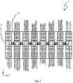
- Fig. 2 illustrates this nicely by showing magnetic field lines in another embodiment of the pinion stack component.
- the alternating magnetic pole orientation is applicable in all embodiments of the present disclosure.
- the rack component 3 and/or the pinion stack component 5 are movable relative to each other along the linear axis L.
- a relative motion along the linear axis L results in a torque on the pinion stack component 5 around the rotor axis R, because the magnetic flux is influenced by the relative position between the bars of the rack component 3 and the teeth 11 of the pinion discs 9a,b,c,d.
- the rotation of the pinion stack component 5 induced by a relative linear motion of the rack component 3 may be used to drive an electric generator, for instance.
- the relative linear motion of the rack component 3 may for instance be induced by heaving forces of sea waves as explained in more detail below.
- a motor may drive the pinion stack component 5 to rotate and thereby induces a linear displacement of the rack component 3.
- the radius of the magnetic discs 13a,b,c is essentially the same as the diameter of the pinion discs 9a,b,c,d from the rotor axis R to the top land 15 of the teeth 11.
- the magnetic discs 13a,b,c are designed as axially thinner and radially smaller without compromising too much on the maximally transferable torque. It was found that the magnetic discs 13a,b,c can be designed axially thinner than the pinion discs 9a,b,c,d.
- the axial thickness of the magnetic discs 13a,b,c may be 30% or more of the axial thickness of the pinion discs 9a,b,c,d without compromising too much on the maximally transferable torque.
- the radial extension of the magnetic discs 13a,b,c can be reduced such that the teeth 11 extend radially further than the diameter of the magnetic discs 13a,b,c (see Figs. 4 , 6 , 8 and 9 ).
- the bottom land 17 of the tooth spaces 19 is in the embodiment of Fig. 1 round with a single circular or oval fillet between neighbouring teeth 11.
- the top land 15 of the teeth 11 is very important for the transfer of magnetic flux. Therefore, the ratio between the angular width of the top land 15 of each tooth 11 and the angular width of the root 21 of each tooth 11 ranges between 0.8 and 1.25, and is preferably essentially 1.
- the embodiment of Fig. 3 differs from the embodiment of Fig. 1 in several aspects.
- the rack component 3 is not a single integral part of ferromagnetic material, but composed of a row of ferromagnetic bars 23 extending along a lateral alignment direction A.
- the lateral alignment direction A does not extend along the x-axis, but is skewed by an angle ⁇ , wherein the angle ⁇ is spanned between a lateral alignment direction A and the x-axis.
- the pinion stack component 5 only comprises three pinion discs 9a,b,c and two magnetic discs 13a,b.
- neighbouring pinion discs 9a,b,c have a rotational position shifted by an angle ⁇ with respect to each other.
- the angle ⁇ is correspondingly chosen so that all pinion discs 9,a,b,c have the same phase with respect to the skewed bars 23 of the rack component 3. This reduces a "sputtering” or “staggering” of the torque transfer.
- the shift angle ⁇ corresponds to a relative angular shift about half the circular width of the teeth 11 between neighbouring pinion discs 9,a,b,c.
- the shape of the teeth 11 is different with a flat bottom land 17 of the tooth spaces 19 and radially extending flanks 25.
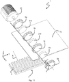
- the embodiment shown in Figs. 4, 5 and 6 has again four pinion discs 9a,b,c,d and three magnetic discs 13a,b,c, wherein no skew angle ⁇ or shift angle ⁇ is applied.
- the shape of the teeth 11 is essentially the same as in Fig. 3 .
- the rack component 3 is a single integral ferromagnetic part with a crenelated top side as shown in Fig. 1 .
- the pinion stack component 5 is coupled to a rotor axle 27 along the rotor axis R for driving an electric generator 29 or to be driven by any kind of motor 29.
- a separating wall structure 31 is placed in the gap 7 between the rack component 7 and the pinion stack component 5.
- Figs. 7 and 8 show a rack component 3 composed of a row of bars 23 without any skew angle ⁇ applied. Otherwise, the embodiment is the same as in Figs. 4, 5 and 6 .
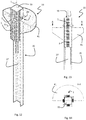
- Figs. 9, 10 and 11 show an integral rack component 3 with a skew angle ⁇ applied to the first pattern of ferromagnetic structure in form of a crenelated top side. Accordingly, a shift angle ⁇ is applied in view of the angular position of neighbouring pinion discs 9a,b,c,d with relative to another.
- the shift angle ⁇ corresponds here to half a tooth width, i.e. 6° for 15 teeth 11 per pinion disc 9a,b,c,d and 15 tooth spaces 19 with the same angular width as the teeth 11.
- the teeth 11 of each pinion disc 9a,b,c,d are skewed by a twist angle ⁇ about the rotor axis R to adapt the shape of the teeth 11 to the skewed rack component 3.
- the ratio between the first period P1 defined by the first pattern of ferromagnetic structure and the second period P2 defined by the second pattern of ferromagnetic structure is approximately 1.25.
- the ratio may be chosen in the range of 0.8 to 1.25.
- all embodiments shown in the Figures have a pinion stack component 5 with an axial through-hole 32 along the rotor axis R for receiving a rotor axle 27.
- the pinion stack component 5 may be arranged in a drum or the stack is held together otherwise so that an axial through-hole 32 is not necessarily needed for the pinion stack component 5.
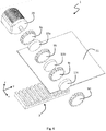
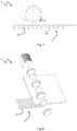
- Figs. 12, 13 and 14 show a sea wave energy conversion system 33 making use of four magnetic rack-and-pinion coupling systems 1 as described above.
- the sea wave energy conversion system 33 comprises a guiding structure 35 defining a tubular inner volume 37 having a squared cross-section and extending longitudinally along a linear axis L, which essentially corresponds to the vertical axis.
- the sea wave energy conversion system 33 further comprises a buoyance body 39 being movable within the tubular inner volume 37 along the linear axis L relative to the guiding structure 35.
- the sea wave energy conversion system 33 further comprises four magnetic rack-and-pinion coupling systems 1, of which one is located at each of the four sides of the tubular inner volume 37.
- Each magnetic rack-and-pinion coupling systems 1 is configured to transfer a linear motion of the buoyance body 39 relative to the guiding structure 35 to a rotational motion of a rotor axis R for driving an associated electric generator 29.
- the rack component 3 of each magnetic rack-and-pinion coupling system 1 extends along the linear axis L at the associated lateral side fixed to the buoyant body 39.
- the pinion stack component 5 and the electric generator 29 are mounted to the guiding structure 35 at the associated lateral side to the tubular inner volume 37.
- the magnetic rack-and-pinion coupling systems 1 are arranged in a fourfold rotational symmetry around the linear axis L at essentially the same height along the linear axis L.
- the guiding structure 35 may be attached and/or moored to a floating, preferably anchored, structure (not shown) in a way which allows almost free vertical motion of the guiding structure 35.
- the guiding structure 35 may be anchored or moored itself or fixed relative to the seabed.
- the guiding structure 35 in the shown embodiments is buoyant due to a buoyance portion 41 of the guiding structure 35.
- the buoyance portion 41 surrounds an upper section of the tubular inner volume 37.
- the guiding structure 35 thus follows heaving forces of sea waves quicker than the buoyance body 39 within the tubular inner volume 37 where it is somewhat shielded from the direct wave influence and therefore reacts with a delay and/or a different frequency. Thereby, the sea waves drive a motion of the buoyant body 39 relative to the buoyant guiding structure 35.
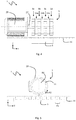
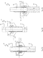
- Figs. 15a,b,c show three different stages of relative linear motion between the buoyance body 39 and the guiding structure 35 of another embodiment of the sea wave energy conversion system 33.
- the pinion stack components 5 of the magnetic rack-and-pinion coupling systems 1 are each enclosed in a housing 43 against the corrosive environment of sea water.
- Fig. 15a shows an equilibrium stage for a flat sea without waves (indicated by a virtual flat sea level NN).
- Fig. 15b shows the stage when a peak of a sea wave W passes the sea wave energy conversion system 33.
- the buoyant guiding structure 35 with the buoyant portion 41 follows quickly and is at a high altitude.
- the buoyance body 39 within the tubular inner volume 37 follows slower and is thus positioned low relative to the guiding structure 35.
- Fig. 15c The opposite stage is shown in Fig. 15c when a trough of a sea wave W passes the sea wave energy conversion system 33.
- the buoyant guiding structure 35 with the buoyant portion 41 follows quickly and is at a low altitude, whereas the water level in the tubular inner volume 37 is still high so that the buoyance body 39 is positioned high relative to the guiding structure 35.
- the magnetic rack-and-pinion coupling systems 1 provide a robust, efficient and low-maintenance solution for transferring the relative linear motion into a rotational torque for driving an electric generator 29, or for transferring a rotational motion of a motor 29 into a linear motion of the rack component 3 relative to the pinion stack component 5.
Landscapes
- Engineering & Computer Science (AREA)
- Power Engineering (AREA)
- Chemical & Material Sciences (AREA)
- Combustion & Propulsion (AREA)
- Mechanical Engineering (AREA)
- General Engineering & Computer Science (AREA)
- Transmission Devices (AREA)
Priority Applications (4)
| Application Number | Priority Date | Filing Date | Title |
|---|---|---|---|
| EP18180948.4A EP3587793A1 (de) | 2018-06-29 | 2018-06-29 | Magnetisches zahnstangenkupplungssystem und meereswellenenergieumwandlungssystem |
| PCT/EP2019/067280 WO2020002568A1 (en) | 2018-06-29 | 2019-06-28 | Magnetic rack-and-pinion coupling system and sea wave energy conversion system |
| EP19735281.8A EP3814625A1 (de) | 2018-06-29 | 2019-06-28 | Magnetisches zahnstangenkupplungssystem und meereswellenenergieumwandlungssystem |
| US17/255,069 US11159081B2 (en) | 2018-06-29 | 2019-06-28 | Magnetic rack-and-pinion coupling system and sea wave energy conversion system |
Applications Claiming Priority (1)
| Application Number | Priority Date | Filing Date | Title |
|---|---|---|---|
| EP18180948.4A EP3587793A1 (de) | 2018-06-29 | 2018-06-29 | Magnetisches zahnstangenkupplungssystem und meereswellenenergieumwandlungssystem |
Publications (1)
| Publication Number | Publication Date |
|---|---|
| EP3587793A1 true EP3587793A1 (de) | 2020-01-01 |
Family
ID=62837805
Family Applications (2)
| Application Number | Title | Priority Date | Filing Date |
|---|---|---|---|
| EP18180948.4A Withdrawn EP3587793A1 (de) | 2018-06-29 | 2018-06-29 | Magnetisches zahnstangenkupplungssystem und meereswellenenergieumwandlungssystem |
| EP19735281.8A Withdrawn EP3814625A1 (de) | 2018-06-29 | 2019-06-28 | Magnetisches zahnstangenkupplungssystem und meereswellenenergieumwandlungssystem |
Family Applications After (1)
| Application Number | Title | Priority Date | Filing Date |
|---|---|---|---|
| EP19735281.8A Withdrawn EP3814625A1 (de) | 2018-06-29 | 2019-06-28 | Magnetisches zahnstangenkupplungssystem und meereswellenenergieumwandlungssystem |
Country Status (3)
| Country | Link |
|---|---|
| US (1) | US11159081B2 (de) |
| EP (2) | EP3587793A1 (de) |
| WO (1) | WO2020002568A1 (de) |
Cited By (1)
| Publication number | Priority date | Publication date | Assignee | Title |
|---|---|---|---|---|
| US20250283446A1 (en) * | 2024-03-11 | 2025-09-11 | Thomas Mitchell Rock | Wave-powered electric generator |
Families Citing this family (1)
| Publication number | Priority date | Publication date | Assignee | Title |
|---|---|---|---|---|
| CN114876708B (zh) * | 2022-04-06 | 2025-05-27 | 中国人民解放军军事科学院系统工程研究院 | 将直线往复运动转化为发电机单向转动的能量传递系统 |
Citations (5)
| Publication number | Priority date | Publication date | Assignee | Title |
|---|---|---|---|---|
| WO1996022630A1 (en) * | 1995-01-21 | 1996-07-25 | Alan Keith Robinson | Improvements relating to magnetic coupling systems |
| WO2004005760A1 (fr) * | 2002-06-21 | 2004-01-15 | Lehan Wei | Type d'engrenage magnetique compose multiplicateur et sa transmission |
| WO2010130821A2 (en) | 2009-05-13 | 2010-11-18 | Wavebob Limited | A wave energy conversion system |
| US20140103765A1 (en) * | 2009-01-14 | 2014-04-17 | Lawrence Livermore National Security, Llc | Gear trains employing magnetic coupling |
| WO2014148349A1 (ja) * | 2013-03-19 | 2014-09-25 | アズビル株式会社 | 磁気リニアアクチュエータ |
Family Cites Families (1)
| Publication number | Priority date | Publication date | Assignee | Title |
|---|---|---|---|---|
| US10090749B2 (en) * | 2014-03-11 | 2018-10-02 | Jak Research, Llc | Magnetic gears for a contactless and frictionless magnetic gear system |
-
2018
- 2018-06-29 EP EP18180948.4A patent/EP3587793A1/de not_active Withdrawn
-
2019
- 2019-06-28 EP EP19735281.8A patent/EP3814625A1/de not_active Withdrawn
- 2019-06-28 US US17/255,069 patent/US11159081B2/en not_active Expired - Fee Related
- 2019-06-28 WO PCT/EP2019/067280 patent/WO2020002568A1/en not_active Ceased
Patent Citations (5)
| Publication number | Priority date | Publication date | Assignee | Title |
|---|---|---|---|---|
| WO1996022630A1 (en) * | 1995-01-21 | 1996-07-25 | Alan Keith Robinson | Improvements relating to magnetic coupling systems |
| WO2004005760A1 (fr) * | 2002-06-21 | 2004-01-15 | Lehan Wei | Type d'engrenage magnetique compose multiplicateur et sa transmission |
| US20140103765A1 (en) * | 2009-01-14 | 2014-04-17 | Lawrence Livermore National Security, Llc | Gear trains employing magnetic coupling |
| WO2010130821A2 (en) | 2009-05-13 | 2010-11-18 | Wavebob Limited | A wave energy conversion system |
| WO2014148349A1 (ja) * | 2013-03-19 | 2014-09-25 | アズビル株式会社 | 磁気リニアアクチュエータ |
Non-Patent Citations (1)
| Title |
|---|
| MCGILTON BEN ET AL: "Review of magnetic gear technologies and their applications in marine energy", IET RENEWABLE POWER GENERATION, THE INSTITUTION OF ENGINEERING AND TECHNOLOGY, MICHAEL FARADAY HOUSE, SIX HILLS WAY, STEVENAGE, HERTS. SG1 2AY, UK, vol. 12, no. 2, 5 February 2018 (2018-02-05), pages 174 - 181, XP006065287, ISSN: 1752-1416, DOI: 10.1049/IET-RPG.2017.0210 * |
Cited By (1)
| Publication number | Priority date | Publication date | Assignee | Title |
|---|---|---|---|---|
| US20250283446A1 (en) * | 2024-03-11 | 2025-09-11 | Thomas Mitchell Rock | Wave-powered electric generator |
Also Published As
| Publication number | Publication date |
|---|---|
| US11159081B2 (en) | 2021-10-26 |
| EP3814625A1 (de) | 2021-05-05 |
| US20210273546A1 (en) | 2021-09-02 |
| WO2020002568A1 (en) | 2020-01-02 |
Similar Documents
| Publication | Publication Date | Title |
|---|---|---|
| EP3587793A1 (de) | Magnetisches zahnstangenkupplungssystem und meereswellenenergieumwandlungssystem | |
| US9124167B2 (en) | Electrical machine | |
| EP2610524B1 (de) | Kraftübertragungsmechanismus | |
| EP3120014B1 (de) | Hydrokinetisches energieumwandlungssystem und verwendung davon | |
| EP2916958B1 (de) | Trommel für magnetscheider und zugehöriges herstellungsverfahren | |
| SE416040B (sv) | Manuellt driven vinsch | |
| CN102723840A (zh) | 圆周割磁流体发电装置 | |
| KR101918011B1 (ko) | 듀얼타입의 파동기어장치 | |
| CN1172426C (zh) | 多层磁啮轮及磁性传动装置 | |
| US20170016424A1 (en) | Apparatuses, methods and systems for harnessing fluid flow with flexible mechanical transducers | |
| EP2938896A2 (de) | Toleranzring mit diskreten toleranzringplatten | |
| US8810099B2 (en) | Power magnetic planetary gear set | |
| WO2018229737A1 (en) | Torque amplifier | |
| KR101834815B1 (ko) | 듀얼타입의 파동기어장치 | |
| WO2012171602A2 (de) | Synchronmotor | |
| KR950010306A (ko) | 리니어 펄스 모터 | |
| US20110124449A1 (en) | Deceleration mechanism and transmission device utilized thereby | |
| US9748805B2 (en) | Generator | |
| US3512757A (en) | Magnetic traction line haul | |
| DK2885203T3 (en) | RING SCREW WITH PREVENTION | |
| CA2566843A1 (en) | Magnetorheological clutch with laminated strips | |
| EP3252936A1 (de) | Reluktanzmagnetgetriebe | |
| US10371241B1 (en) | Stress-wave actuator and reducer | |
| CA3156013A1 (en) | GEAR WHEEL | |
| KR101227458B1 (ko) | 코깅 감소용 마그네틱 기어 및 이를 이용한 이송장치 |
Legal Events
| Date | Code | Title | Description |
|---|---|---|---|
| PUAI | Public reference made under article 153(3) epc to a published international application that has entered the european phase |
Free format text: ORIGINAL CODE: 0009012 |
|
| STAA | Information on the status of an ep patent application or granted ep patent |
Free format text: STATUS: THE APPLICATION HAS BEEN PUBLISHED |
|
| AK | Designated contracting states |
Kind code of ref document: A1 Designated state(s): AL AT BE BG CH CY CZ DE DK EE ES FI FR GB GR HR HU IE IS IT LI LT LU LV MC MK MT NL NO PL PT RO RS SE SI SK SM TR |
|
| AX | Request for extension of the european patent |
Extension state: BA ME |
|
| STAA | Information on the status of an ep patent application or granted ep patent |
Free format text: STATUS: THE APPLICATION IS DEEMED TO BE WITHDRAWN |
|
| 18D | Application deemed to be withdrawn |
Effective date: 20200702 |