EP3587786B1 - Akustikpaneel für schubumkehrvorrichtungen - Google Patents
Akustikpaneel für schubumkehrvorrichtungen Download PDFInfo
- Publication number
- EP3587786B1 EP3587786B1 EP19177596.4A EP19177596A EP3587786B1 EP 3587786 B1 EP3587786 B1 EP 3587786B1 EP 19177596 A EP19177596 A EP 19177596A EP 3587786 B1 EP3587786 B1 EP 3587786B1
- Authority
- EP
- European Patent Office
- Prior art keywords
- composite material
- layer
- cantilevered portion
- base
- acoustic panel
- Prior art date
- Legal status (The legal status is an assumption and is not a legal conclusion. Google has not performed a legal analysis and makes no representation as to the accuracy of the status listed.)
- Active
Links
Images







Classifications
-
- F—MECHANICAL ENGINEERING; LIGHTING; HEATING; WEAPONS; BLASTING
- F02—COMBUSTION ENGINES; HOT-GAS OR COMBUSTION-PRODUCT ENGINE PLANTS
- F02K—JET-PROPULSION PLANTS
- F02K1/00—Plants characterised by the form or arrangement of the jet pipe or nozzle; Jet pipes or nozzles peculiar thereto
- F02K1/78—Other construction of jet pipes
- F02K1/82—Jet pipe walls, e.g. liners
- F02K1/827—Sound absorbing structures or liners
-
- B—PERFORMING OPERATIONS; TRANSPORTING
- B64—AIRCRAFT; AVIATION; COSMONAUTICS
- B64C—AEROPLANES; HELICOPTERS
- B64C1/00—Fuselages; Constructional features common to fuselages, wings, stabilising surfaces or the like
- B64C1/40—Sound or heat insulation, e.g. using insulation blankets
-
- B—PERFORMING OPERATIONS; TRANSPORTING
- B64—AIRCRAFT; AVIATION; COSMONAUTICS
- B64D—EQUIPMENT FOR FITTING IN OR TO AIRCRAFT; FLIGHT SUITS; PARACHUTES; ARRANGEMENT OR MOUNTING OF POWER PLANTS OR PROPULSION TRANSMISSIONS IN AIRCRAFT
- B64D29/00—Power-plant nacelles, fairings or cowlings
-
- F—MECHANICAL ENGINEERING; LIGHTING; HEATING; WEAPONS; BLASTING
- F02—COMBUSTION ENGINES; HOT-GAS OR COMBUSTION-PRODUCT ENGINE PLANTS
- F02C—GAS-TURBINE PLANTS; AIR INTAKES FOR JET-PROPULSION PLANTS; CONTROLLING FUEL SUPPLY IN AIR-BREATHING JET-PROPULSION PLANTS
- F02C7/00—Features, components parts, details or accessories, not provided for in, or of interest apart form groups F02C1/00 - F02C6/00; Air intakes for jet-propulsion plants
- F02C7/24—Heat or noise insulation
-
- F—MECHANICAL ENGINEERING; LIGHTING; HEATING; WEAPONS; BLASTING
- F02—COMBUSTION ENGINES; HOT-GAS OR COMBUSTION-PRODUCT ENGINE PLANTS
- F02K—JET-PROPULSION PLANTS
- F02K1/00—Plants characterised by the form or arrangement of the jet pipe or nozzle; Jet pipes or nozzles peculiar thereto
- F02K1/54—Nozzles having means for reversing jet thrust
- F02K1/64—Reversing fan flow
- F02K1/70—Reversing fan flow using thrust reverser flaps or doors mounted on the fan housing
- F02K1/72—Reversing fan flow using thrust reverser flaps or doors mounted on the fan housing the aft end of the fan housing being movable to uncover openings in the fan housing for the reversed flow
-
- F—MECHANICAL ENGINEERING; LIGHTING; HEATING; WEAPONS; BLASTING
- F05—INDEXING SCHEMES RELATING TO ENGINES OR PUMPS IN VARIOUS SUBCLASSES OF CLASSES F01-F04
- F05D—INDEXING SCHEME FOR ASPECTS RELATING TO NON-POSITIVE-DISPLACEMENT MACHINES OR ENGINES, GAS-TURBINES OR JET-PROPULSION PLANTS
- F05D2250/00—Geometry
- F05D2250/20—Three-dimensional
- F05D2250/28—Three-dimensional patterned
- F05D2250/283—Three-dimensional patterned honeycomb
-
- F—MECHANICAL ENGINEERING; LIGHTING; HEATING; WEAPONS; BLASTING
- F05—INDEXING SCHEMES RELATING TO ENGINES OR PUMPS IN VARIOUS SUBCLASSES OF CLASSES F01-F04
- F05D—INDEXING SCHEME FOR ASPECTS RELATING TO NON-POSITIVE-DISPLACEMENT MACHINES OR ENGINES, GAS-TURBINES OR JET-PROPULSION PLANTS
- F05D2260/00—Function
- F05D2260/96—Preventing, counteracting or reducing vibration or noise
-
- F—MECHANICAL ENGINEERING; LIGHTING; HEATING; WEAPONS; BLASTING
- F05—INDEXING SCHEMES RELATING TO ENGINES OR PUMPS IN VARIOUS SUBCLASSES OF CLASSES F01-F04
- F05D—INDEXING SCHEME FOR ASPECTS RELATING TO NON-POSITIVE-DISPLACEMENT MACHINES OR ENGINES, GAS-TURBINES OR JET-PROPULSION PLANTS
- F05D2300/00—Materials; Properties thereof
- F05D2300/60—Properties or characteristics given to material by treatment or manufacturing
- F05D2300/603—Composites; e.g. fibre-reinforced
-
- Y—GENERAL TAGGING OF NEW TECHNOLOGICAL DEVELOPMENTS; GENERAL TAGGING OF CROSS-SECTIONAL TECHNOLOGIES SPANNING OVER SEVERAL SECTIONS OF THE IPC; TECHNICAL SUBJECTS COVERED BY FORMER USPC CROSS-REFERENCE ART COLLECTIONS [XRACs] AND DIGESTS
- Y02—TECHNOLOGIES OR APPLICATIONS FOR MITIGATION OR ADAPTATION AGAINST CLIMATE CHANGE
- Y02T—CLIMATE CHANGE MITIGATION TECHNOLOGIES RELATED TO TRANSPORTATION
- Y02T50/00—Aeronautics or air transport
- Y02T50/60—Efficient propulsion technologies, e.g. for aircraft
Definitions
- the present disclosure is generally related to acoustic panels including a cantilevered doubler.
- Airplanes with jet engines are often equipped with thrust reversers that increase drag on the airplane during landings, thereby reducing the speed of the aircraft.
- a thrust reverser increases drag by effectively reversing the flow of bypass or exhaust gases through the jet engine.
- a transcowl on the jet engine nacelle translates rearwardly to redirect the airflow forwardly and thereby produce reverse thrust.
- the transcowl is coupled to an acoustic panel which reduces engine noise and provides aerodynamic surfaces on both sides (inside and outside surfaces) of the acoustic panel.
- the acoustic panel is a complex part because it has very high design requirements for noise reduction, aerodynamic drag, and structural support.
- the acoustic panel is coupled to the transcowl via fasteners that go through the entire thickness of the acoustic panel, fasteners that only attach to one facesheet of the acoustic panel, or adhesives. When fasteners are used, the area where the acoustic panel is coupled to transcowl may not be acoustically active and may be heavier because fasteners are used to join the two pieces.
- Document US 4,826,106 A relates to an aircraft cowl, and in particular a translating cowl, used as a component of a thrust reverser, formed of at least one-piece bondment cured in a single operation.
- a one-piece inner bondment and a one-piece outer bondment fastened together at a joining region.
- the bondments have constant density cores and tapered closures.
- Acoustically absorbing materials are part of the lay up for one of the bondments and are integrally cured therein.
- a vehicle for a thrust reverser.
- a vehicle includes an engine, a cowl partially enclosing the engine, and a thrust reverser assembly.
- the thrust reverser assembly is coupled to the cowl.
- the thrust reverser assembly includes a transcowl and includes an acoustic panel configured to attenuate noise from the engine.
- the acoustic panel includes a base having a surface defining a plurality of cavities.
- the acoustic panel also includes a cantilevered portion extending from the base and configured to be removably coupled with a portion of the transcowl.
- the acoustic panel includes a gap defined by the base and the cantilevered portion.
- the acoustic panel further includes a support member coupled to the cantilevered portion and coupled to the base, the support member configured to support the cantilevered portion.
- a method of manufacturing an acoustic panel for a thrust reverser also includes applying a layup support member to the layer of composite materials.
- the method further includes forming a cantilevered portion extending from the base.
- the layup support material is positioned between the base and the cantilevered portion. After forming, the cantilevered portion is configured to be coupled to and support another component, and a portion of a surface of the cantilevered portion is an aerodynamic surface.
- the cantilevered portion can be attached to another component and the acoustic panel has an increased acoustically active area, a potential for a lower weight configuration, and offers easier maintenance and servicing of the acoustic panels. Additionally, maintaining and servicing the acoustic panel does not degrade performance like compared to conventional configurations. Accordingly, engine noise is decreased, which leads to less noise pollution and enables an aircraft to operate during restricted noise times.
- the disclosed embodiments provide a lighter and higher performing acoustic panel for use in thrust reversers to make the thrust reversers easier to assemble and disassemble.
- a method of manufacturing the acoustic panel is also disclosed.
- Thrust reversers are commonly included in or form a portion of a nacelle of an aircraft.
- acoustic performance, manufacturing costs, and repairability are major factors.
- Acoustic performance is primarily affected by an amount of surface area that is acoustically active, i.e., a larger acoustically active area reduces engine noise output. For example, the acoustically active area vibrates to dissipate or dampen noise generated by the engine.
- fasteners e.g., removable fasteners
- Special permanent fasteners e.g., blind permanent fasteners that only attach to one facesheet of the acoustic panel and that penetrate the acoustically active area
- blind permanent fasteners can be used to limit the reduction in acoustically active area, but upon servicing the part or area, the benefit is lost.
- Nacelle components are high value components and are expensive to produce because their structural and functional requirements (e.g., aerodynamic and acoustical properties).
- the manufacturing of nacelle components includes multiple tools, machines, and processes.
- a thrust reverser outer acoustic panel has aerodynamic requirements on both the outer and inner surfaces, and is the most expensive component of the thrust reverser.
- In-service repairs are common as nacelles are exposed to both man-made and natural damage. The close proximity of these structures to the ground and regular engine maintenance requirements makes them very susceptible to damage from tool drop, handling, and support vehicles. Nacelles are also commonly exposed to natural damage such as lightning strikes and hail strikes.
- the acoustic panels described herein include a cantilevered portion that extends outwards from a base of the acoustic panel.
- the cantilevered portion is supported by a support member and is configured to attach to another component, such as the transcowl.
- the cantilevered portion simplifies bond panel manufacturing operations, reduces weight, increases the acoustically active area, and makes the translating sleeve more repairable.
- Cantilevering an attachment area e.g., an attachment flange
- an attachment area e.g., an attachment flange
- transcowl can attach to this attachment area using a nut plate and bolt. Furthermore, disassembly of the transcowl from the cantilevered portion does not result in an acoustically active area loss and can be done with less specialized tools as compared to conventional configurations.
- FIG. 1 illustrates a block diagram of an example of an aircraft 100 that includes a nacelle 102 and a propulsor 112.
- the nacelle 102 is configured to house the propulsor 112 and to be coupled to the aircraft 100.
- the propulsor 112 is housed within the nacelle 102 and is configured to generate thrust.
- the propulsor 112 includes or corresponds to a jet engine or another type of propulsor.
- the nacelle 102 includes a cowl 114 and a thrust reverser assembly 116 (referred to herein as a thrust reverser 116).
- the nacelle 102 is coupled to the aircraft 100 via a strut or a pylon.
- the nacelle 102 can be connected to a wing of the aircraft 100, a fuselage of the aircraft 100, or an empennage (tail section) of the aircraft 100.
- the cowl 114 is configured to house (partially encase or enclose) the propulsor 112 and includes multiple sections or pieces. As illustrated in FIG. 1 , the cowl 114 includes an inlet cowl 122. The cowl 114 is configured to reduce propulsor noise, to protect the propulsor 112, and to direct airflow to the propulsor 112. In some implementations, the cowl 114 includes a second portion (e.g., a fan cowl 212 of FIG. 2 ). The second portion (e.g., the fan cowl 212) may form an intermediary portion of the nacelle 102 and may be positioned between the inlet cowl 122 and a transcowl 124.
- a second portion e.g., a fan cowl 212 of FIG. 2
- the thrust reverser 116 is configured to generate thrust.
- the thrust reverser 116 is configured to generate forward thrust in a first configuration and is configured to generate reverse thrust in a second configuration.
- the reverse thrust includes thrust in a direction opposite the propulsor 112, thrust in a direction that opposes a direction of travel of the aircraft 100, and/or thrust that reduces the forward thrust (e.g., thrust that propels the aircraft 100 in a forward direction).
- the thrust reverser 116 includes or corresponds to a translating thrust reverser, a cascade thrust reverser, a cold stream thrust reverser, a clamshell thrust reverser, or a combination thereof.
- the thrust reverser 116 vents bypass airflow from the propulsor 112 out of an opening in the nacelle 102.
- the opening in the nacelle 102 is created by the transcowl 124 translating rearwards or aft from the cowl 114 (e.g., the inlet cowl 122 and/or the fan cowl 212 of FIG. 2 ), as described further with respect to FIGS. 2-4 .
- the thrust reverser 116 is coupled (e.g., moveably coupled) to the cowl 114 and includes the transcowl 124 and an acoustic panel 132 configured to reduce or attenuate propulsor noise.
- the acoustic panel 132 also directs airflow within the nacelle 102 and forms an outer portion of the nacelle 102.
- the acoustic panel 132 has aerodynamic surfaces.
- the aerodynamic surfaces are configured to provide low drag.
- the surfaces (or portions of the surfaces) of the acoustic panel 132 are machined to have a contour that reduces drag and have a composition (e.g., a surface material and/or smoothness) that reduces drag.
- the acoustic panel 132 includes a base 142, a cantilevered portion 144, and a support member 146.
- the base 142, the cantilevered portion 144, and the support member 146 are joined (e.g., fixedly coupled or fixedly adhered) to form a monolithic piece. Fabrication of the acoustic panel 132 is further described with reference to FIGS. 9-13 and 18 .
- the acoustic panel 132 i.e., the cantilevered portion 144 thereof
- the acoustic panel 132 forms and/or defines an exterior portion or surface of the nacelle 102.
- the nacelle 102 e.g., the cowl 114 thereof
- the base 142 (e.g., a base member) includes a plurality of cavities configured to reduce or attenuate propulsor noise.
- the base 142 includes a plurality of hexagonal shaped (e.g., honeycomb shaped) cavities that dampen or absorb sound waves and block sound waves generated by the propulsor 112.
- the hexagonal shaped cavities also provide a relatively high degree of strength per weight and are repeatable without overlaps or gaps (i.e., hexagonal shaped cavities are capable of being efficiently tessellated).
- the cantilevered portion 144 is configured to couple to a portion of the transcowl 124.
- the cantilevered portion 144 is coupled to the transcowl 124 via fasteners, as described further with reference to FIG. 17 .
- the cantilevered portion 144 may include or correspond to a doubler (or a portion thereof), as described further with reference to FIG. 8 .
- a doubler is a laminated support member and is often used as a support for a skin or an external portion of the aircraft 100.
- coupling the cantilevered portion 144 to the transcowl 124 increases the acoustically active area of the acoustic panel 132, reduces a weight of the acoustic panel 132, and facilitates maintenance and servicing without performance losses.
- the support member 146 is configured to support the cantilevered portion 144 and to absorb loads during operation of the aircraft 100.
- the support member 146 may include or correspond to a noodle 814 or a molded insert 1512, as described with reference to FIGS. 8 and 15 .
- the propulsor 112 is included in a fuselage or empennage of the aircraft 100, such as in a tri-jet aircraft.
- the cantilevered portion 144 is coupled to a portion of the fuselage or empennage of the aircraft instead of being coupled to a portion of the transcowl 124.
- the acoustic panel 132 has been described as an acoustic panel (e.g., an outer acoustic panel or wall) of a thrust reverser 116, the acoustic panel 132 may couple to other components.
- the aerodynamic surfaces of the acoustic panel 132 provide low drag and the cantilevered portion 144 allows the acoustic panel 132 to be coupled with other components and provide a higher quality aerodynamic surface.
- the acoustic panel 132 may be coupled to flight control surfaces and components thereof.
- the acoustic panel 132 may be manufactured by exemplary methods of manufacturing described with reference to FIGS. 9-13 and 18 . Additionally, the methods of manufacturing the acoustic panel 132 can be applied to manufacturing other components to increase an active area of a base member thereof, to join two components to form an aerodynamic surface, or to couple a second component to a first component via a cantilevered portion 144 rather than via a base 142 of the first component, such as for design constraints (e.g., repairability, manufacturing time, costs, etc.).
- design constraints e.g., repairability, manufacturing time, costs, etc.
- FIG. 2 is a diagram 200 that illustrates a side view of the nacelle 102 of the aircraft 100 depicting the transcowl 124 having shifted rearwardly (as indicated by the arrow) to expose the (cascade-type) thrust reverser 116.
- FIG. 3 is a diagram 300 that illustrates a perspective view of the nacelle 102 and the thrust reverser 116 shown in FIG. 2 .
- FIG. 4 is a diagram 400 that illustrates a cross-section view of a portion of the nacelle 102 shown in FIGS. 2 and 3 , depicting airflow through the thrust reverser 116.
- the cascade-type thrust reverser 116 includes a plurality of circumferentially arranged, thrust reversing cascade grid panels 202, sometimes referred to as cascade baskets.
- the transcowl 124 is in a closed, forward position, joining the transcowl 124 with the cowl 114 (e.g., the inlet cowl 122 and/or the fan cowl 212), and thereby covering the cascade grid panels 202.
- the transcowl 124 is moved from its closed position to its open, rearwardly extended position (as shown in FIGS. 2-4 ) by actuator rods 410 of FIG. 4 . Opening the transcowl 124 exposes the cascade grid panels 202 to the surrounding environment.
- the thrust reverser 116 is activated by deploying circumferentially located blocker doors 408 of FIG. 4 . Deploying the blocker doors 408 prevents bypass exhaust from flowing out of a nozzle 312 of FIG. 3 and forces the bypass exhaust through the cascade grid panels 202, as shown by the arrows 412 in FIG. 4 .
- Each of the cascade grid panels 202 includes a plurality of axially extending strongbacks (not shown), a plurality of vanes 406 extending between the strongbacks, and fore and aft mounting flanges 402, 404 respectively.
- the cascade grid panels 202 direct the flow of the exhaust forward, and optionally radially outward, producing a reversal in the direction of the exhaust flow. This reversal of the bypass exhaust flow results in a reversal of thrust that assists in slowing down the aircraft 100.
- the acoustic panel 132 is coupled to the transcowl 124 and forms an exterior portion of the nacelle 102.
- an exterior surface (i.e., an aerodynamic surface) of the acoustic panel 132 corresponds to or forms a portion of an exterior portion of the nacelle 102 (e.g., forms a portion of the transcowl 124).
- FIG. 4 also illustrates that an interior surface of the acoustic panel 132 defines the nozzle 312 and is a second aerodynamic surface which directs the bypass exhaust when the transcowl 124 is in the forward or closed position.
- the acoustic panel 132 (e.g., the plurality of cavities thereof) attenuates noise produced by the propulsor 112.
- FIG. 5 is a diagram 500 that illustrates a cross-section view of an example of the acoustic panel 132 of FIG. 1 . Because the acoustic panel 132 is annular shaped, the cross-section illustrated in FIG. 5 includes an upper portion 512 (e.g., an upper-cross section) and a lower portion 514 (e.g., a lower cross-section). The acoustic panel 132 of FIG. 5 has a similar shape to the shape of the acoustic panel 132 of FIGS. 3 and 4 .
- the acoustic panel 132 includes aerodynamic surfaces 522, 524.
- a first aerodynamic surface 522 includes or corresponds to an exterior or external aerodynamic surface, i.e., an aerodynamic surface for exterior airflow of the nacelle 102.
- a second aerodynamic surface 524 includes or corresponds to an interior aerodynamic surface, i.e., an aerodynamic surface for fan duct bypass air flowing out of the nozzle 312 of FIG. 3 (when the blocker doors 408 of FIG. 4 are stowed).
- the upper portion 512 includes aerodynamic surfaces 522A and 524A and the lower portion 514 includes aerodynamic surfaces 522B and 524B.
- the upper portion 512 illustrates two areas of the acoustic panel 132 in dashed boxes, a fore portion 532 and an aft portion 534.
- the fore portion 532 includes a first machined transition area 542. In the machined transition areas, a surface of the acoustic panel 132 may be machined, processed, or finished to meet design requirements regarding a thickness of the acoustic panel 132.
- the aft portion 534 includes that cantilevered portion 144 and the support member 146.
- a second machined transition area 544 begins near the aft portion 534 (e.g., at the cantilevered portion) and extends rearward or aftward. The second machined transition area 544 may extend to a rear or aft end of the acoustic panel 132 in some implementations.
- FIG. 6 illustrates a side view of the acoustic panel 132 of FIG. 5 .
- the machined transition areas 542, 544 are shown in dashed boxes 612.
- the cross-section of the acoustic panel 132 is not the same over the entire span of the acoustic panel 132, i.e., the acoustic panel 132 may be non-symmetrical with respect to a particular axis.
- the nacelle 102 may include multiple acoustic panels 132, each acoustic panel 132 may have a different shape than another acoustic panel 132.
- the acoustic panel 132 has a reduction in machined transition areas 542, 544 (e.g., machined transitions surfaces).
- machined transition areas 542, 544 e.g., machined transitions surfaces
- the entire acoustic panel 132 has machined surfaces, which increases fabrication time and costs.
- FIGS. 7A-7C illustrate an example of the acoustic panel 132 and the base 142 thereof.
- FIG. 7A is a diagram that illustrates a cross-section view of the fore portion 532 of the acoustic panel 132 of FIG. 3 .
- the base 142 of the acoustic panel 132 has a first surface 712 and a second surface 714.
- the base 142 includes a plurality of cavities 722, as illustrated in FIG. 7B , positioned (e.g., sandwiched) between two facesheets 742, 744, as illustrated in FIG. 7C .
- FIG. 7B depicts surfaces 732, 734 of the base 142 defining the plurality of cavities 722.
- the plurality of cavities 722 of the base 142 have a hexagonal shape (e.g., a honeycomb shape), and the base 142 includes or corresponds to a "honeycomb structure" with the plurality of cavities 722 forming a "core" of the honeycomb structure.
- one or more of the plurality of cavities 722 have other shapes, such as a circular shape, a rectangular shape, a square shape, a pentagonal shape, an octagonal shape, another shape which may be tessellated, or a combination thereof.
- the plurality of cavities 722 are illustrated in FIG.
- the plurality of cavities 722 correspond to through holes and are defined by both surfaces 732, 734.
- the plurality of cavities 722 do not extend through the acoustic panel 132.
- each of the surfaces 732, 734 defines a corresponding plurality of cavities 722.
- the acoustic panel 132 (e.g., portions thereof) includes facesheets 742, 744 coupled to the surfaces 732, 734 that define the plurality of cavities 722 of the base 142, as illustrated in FIG. 7C .
- the facesheets 742, 744 include composite material, as further described with reference to FIG. 8 .
- the facesheets 742, 744 may include or correspond to a skin of the acoustic panel 132 (and the nacelle 102) and include the surfaces 712, 714.
- FIG. 8 illustrates a cross-section view of an example of the aft portion 534 of the acoustic panel 132 of FIG. 3 .
- the aft portion 534 of the acoustic panel 132 includes the base 142, the cantilevered portion 144, and the support member 146.
- the base 142 includes a top surface (corresponding to the first surface 712 of FIG. 7 ) and a bottom surface (corresponding to the second surface 714 of FIG. 7 ).
- a first layer of composite material 812 is coupled to at least a portion of the top surface of the base 142.
- the first layer of composite material 812 is configured to adhere or secure a doubler 816 to the base 142, as described with reference to FIGS. 9-13 .
- the doubler 816 is coupled to the base 142 and extends from the base 142 defining a gap 820. As illustrated in FIG. 8 , the doubler 816 is in contact with the first layer of composite material 812 and is in contact with the base 142. In other implementations, the doubler 816 is in contact with the first layer of composite material 812 and the first layer of composite material 812 is in contact with the first surface 712 (e.g., the top surface) of the base 142.
- the doubler 816 includes a proximal end 832 (proximal portion) and a distal end 834 (distal portion).
- the proximal end 832 is fixed or anchored to the base 142, such as a fixed or anchored end.
- the distal end 834 is free or floating relative to the base 142, such as a free end.
- a portion of the doubler 816 near and including the distal end 834 includes or corresponds to the cantilevered portion 144 of FIG. 1 , as depicted in FIG. 8 .
- the cantilevered portion 144 of the doubler 816 is configured to be coupled to the transcowl 124 of FIG. 1 (or another component).
- the cantilevered portion 144 is removably coupled with the transcowl 124 by fasteners (not shown in FIG. 8 ), as illustrated and described with reference to FIG. 17 .
- the doubler 816 includes composite material, such as carbon fiber reinforced polymers (CFRP).
- CFRP carbon fiber reinforced polymers
- the doubler 816 is pre-formed (e.g., pre-cured) prior to attachment to the base 142 and assembly/formation of the acoustic panel 132, as described with reference to FIGS. 9-13 and 18 .
- the doubler 816 is formed by disposing composite materials (e.g., uncured composite materials) onto the base 142 (or layers and components thereof) and curing the composite materials to form the doubler 816.
- a gap 820 is formed between and defined by the cantilevered portion 144 of the doubler 816 and the base 142.
- a support member 146 is positioned between the doubler 816 and the base 142. As illustrated in FIG. 8 , the support member 146 is a noodle 814 and is positioned between and in contact with the first layer of composite material 812 and the doubler 816.
- the noodle 814 is configured to support the doubler 816.
- the noodle 814 supports the doubler 816 during operation and when coupled to the transcowl 124 of FIG. 1 .
- a separate component or material e.g., a layup support member 1112 of FIG. 11 ) may be used to support the doubler 816 during attachment of the doubler 816 to the base 142 or during formation of the doubler 816, as described with reference to FIG. 12 .
- the noodle 814 includes a material having similar properties to the surrounding materials.
- the noodle 814 includes a material that has similar elasticity and strength to the composite materials of the doubler 816 and the layers of composite material 812, 818, 822.
- the acoustic panel 132 further includes a second layer of composite material 818 coupled to the first layer of composite material 812, the support member 146, and the doubler 816.
- the second layer of composite material 818 is configured to support the cantilevered portion 144 during operation and to couple (e.g., secure) the support member 146 to the first layer of composite material 812 and the base 142.
- the acoustic panel 132 includes adhesive 824.
- the acoustic panel 132 includes a layer of the adhesive 824 positioned between the second layer of composite material 818 and each of the first layer of composite material 812, the noodle 814, and the doubler 816.
- the adhesive 824 is configured to couple (e.g. fixedly couple or adhere) the second layer of composite material 818 to each of the first layer of composite material 812, the noodle 814, and the doubler 816.
- the adhesive 824 is an epoxy-type adhesive. In other implementations, other type of adhesives can be used which can join composite materials.
- a third layer of composite material 822 is coupled to the second surface 714 (e.g., the bottom surface) of the base 142.
- the composite material of the layers of composite material 812, 818, 822 may include or correspond to uncured composite material.
- the composite material of the layers of composite material 812, 818, 822 include uncured (e.g., "green") CFRP plies.
- the composite material of the layers of composite material 812, 818, 822 may include the same type of composite material or different types of composite material.
- the layers of composite material 812, 822 may include or correspond to facesheets, such as the facesheets 742, 744 of FIG. 7 .
- the doubler 816 is tapered 862.
- the distal end 834 of the doubler 816 is thicker than the proximal end 832 of the doubler 816.
- FIG. 8 illustrates the aerodynamic surface 522 and 524 of FIG. 5 .
- a portion of the cantilevered portion 144 forms a portion of the first aerodynamic surface 522 of the acoustic panel 132.
- a portion of the surface of cantilevered portion 144 that is aftward or rearward of the transcowl 124 and extends in towards the aft of the acoustic panel 132 forms a portion of the first aerodynamic surface 522 of the acoustic panel 132.
- FIG. 9 is a diagram 900 illustrating a first manufacturing stage of a process of manufacturing an acoustic panel 132 according to a particular aspect of the disclosure.
- the first manufacturing stage includes placing the base 142 on a tool 902 and depositing the first layer of composite material 812 on at least a portion of the base 142.
- the first layer of composite material 812 has a tapered section 912 near an aft end of the first layer of composite material 812.
- the tapered section 912 may extend further forward or the entire layer of the composite material 812 may be tapered.
- the layer of composite material 812 may extend to the aft edge of the base 142.
- the first layer of composite material 812 may be applied or deposited by hand or by machine.
- the composite material of the first layer of composite material 812 is uncured (e.g., "green") CFRP plies.
- the tool 902 is configured to support components of the acoustic panel 132 during layup and curing of the components of the acoustic panel 132.
- the tool 902 includes a geometry or shape that is configured to support formation of the acoustic panel 132 or components thereof. Although a single tool 902 is illustrated in FIGS. 9-13 , multiple tools 902 may be used in other implementations.
- the third layer of composite material 822 is deposited prior to depositing the first layer of composite material 812, as illustrated in FIG. 9 . In other implementations, the third layer of composite material 822 is deposited after depositing the first layer of composite material 812. Applying the third layer of composite material 822 to the base 142 may be done similar to applying the first layer of composite material 812. For example, the third layer of composite material 822 is deposited on the tool 902 and the base 142 is applied on top of the third layer of composite material 822 or the base 142 is placed on the tool 902 or another tool and the third layer of composite material 822 is applied to the base 142 by hand or by machine.
- the first manufacturing stage further includes a curing step to cure the first layer of composite material 812, the third layer of composite material 822, or both.
- the first layer of composite material 812, the third layer of composite material 822, or both can be cured during a later manufacturing stage.
- the third layer of composite material 822 can be cured at an earlier manufacturing stage.
- FIG. 10 is a diagram 1000 illustrating a second manufacturing stage of a process of manufacturing the acoustic panel 132 according to a particular aspect of the disclosure.
- the second manufacturing stage illustrated in FIG. 10 may be subsequent to the first manufacturing stage of FIG. 9 .
- support material 1012 (which is cured to form the support member 146 of FIG. 1 ) is deposited or applied to the base 142. As illustrated in FIG. 10 , the support material 1012 is deposited on and is in contact with the first layer of composite material 812.
- the support material 1012 may include or correspond to composite materials, such as uncured CFRP, or another material which has material properties similar to the composite materials.
- the support member 146 is placed or positioned on the base 142. In such implementations, the support member 146 is pre-cured, pre-formed, or machined prior to placement on the base 142.
- the second manufacturing stage further includes a curing step to cure the support material 1012, the first layer of composite material 812, the third layer of composite material 822, or a combination thereof.
- the support material 1012, the first layer of composite material 812, the third layer of composite material 822, or a combination thereof can be cured during a later manufacturing stage.
- FIG. 11 is a diagram 1100 illustrating a third manufacturing stage of a process of manufacturing the acoustic panel 132 according to a particular aspect of the disclosure.
- the third manufacturing stage illustrated in FIG. 11 may be subsequent to the second manufacturing stage of FIG. 10 .
- a layup support member 1112 and the second layer of composite material 818 are placed or positioned on the base 142.
- the second layer of composite material 818 is applied to the layup support member 1112 and the joined layup support member 1112 and second layer of composite material 818 is positioned on the base 142 (e.g., positioned in the gap 820 illustrated in FIG. 8 ).
- the second layer of composite material 818 is in contact with the layup support member 1112, the first layer of composite material 812, and the support member 146 or the support material 1012.
- the layup support member 1112 may include or correspond to a rubber material, as an illustrative, non-limiting example.
- the layup support member 1112 can include or correspond to other materials that can support composite materials under heat and/vacuum pressure without deforming outside of design tolerances.
- the layup support member 1112 is configured to support the second layer of composite material 818 and the cantilevered portion 144 prior to coupling the cantilevered portion to the base 142, as described with reference to FIG. 12 .
- the third manufacturing stage further includes applying the adhesive 824 to at least a portion of an outside surface of the second layer of composite material 818.
- the adhesive 824 may be applied to the second layer of composite material 818 before or after deposition of the second layer of composite material 818 onto the layup support member 1112. Additionally or alternatively, the adhesive 824 is applied to first layer of composite material 812, the support material 1012, the support member 146, or another component that the second layer of composite material is coupled to.
- the third manufacturing stage further includes curing the second layer of composite material 818, the support material 1012, the first layer of composite material 812, the third layer of composite material 822, the adhesive 824, or a combination thereof.
- the second layer of composite material 818, the support material 1012, the first layer of composite material 812, the third layer of composite material 822, the adhesive 824, or a combination thereof can be cured during a later manufacturing stage.
- FIG. 12 is a diagram 1200 illustrating a fourth manufacturing stage of a process of manufacturing the acoustic panel 132 according to a particular aspect of the disclosure.
- the fourth manufacturing stage illustrated in FIG. 12 may be subsequent to the third manufacturing stage of FIG. 11 .
- a pre-cured (pre-formed) composite component 1216 (e.g., the doubler 816) is placed on the base 142, the support member 146, and the layup support member 1112 to form the cantilevered portion 144 and the gap 820.
- the components are then cured to secure the pre-cured (pre-formed) composite component 1216 to the base 142 to form the doubler 816 and the cantilevered portion 144.
- the components are cured in an autoclave or formed by a draping process (e.g., hot draping or vacuum deposition).
- uncured composite material (referred to as second composite material) is deposited on the second layer of composite material 818, the support member 146 (e.g., the support material 1012), and/or the layup support member 1112 and is cured to form the cantilevered portion 144.
- second composite material is laid up on one or more of the support member 146 (e.g., the support material 1012) and the second layer of composite material 818 (which is supported by the layup support member 1112), and a rigid tool (e.g., a caul plate) is placed on top of the second composite material. Heat and pressure are applied to the caul plate during a curing process, and the caul plate transfers the heat and pressure to cure the second composite material.
- curing the second composite material using the caul plate can be used to cure one or more layers of composite material 812, 818, 822, the support material 1012, or a combination thereof.
- the layup support member 1112, the second layer of composite materials 818, or both may extend to or past the distal portion of the cantilevered portion 144, as illustrated in FIG. 12 .
- the second layer of composite material 818 is formed such that the second layer of composite material 818 extends to the distal end 834 of the cantilevered portion 144 and the pre-cured (pre-formed) composite component 1216 and the second layer of composite material 818 is later reduced (e.g., by cutting or machining) such that the second layer of composite material 818 does not extend to the distal end 834 (similar to the second layer of composite material 818 of FIG. 8 ).
- the second layer of composite material 818 is formed such that it does not extend to distal end 834 of the cantilevered portion 144 and the pre-cured (pre-formed) composite component 1216.
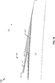
- FIG. 13 is a diagram 1300 illustrating a fifth manufacturing stage of a process of manufacturing the acoustic panel 132 according to a particular aspect of the disclosure.
- the fifth manufacturing stage illustrated in FIG. 13 may be subsequent to the fourth manufacturing stage of FIG. 12 .
- the layup support member 1112 is removed and the gap 820 is formed.
- the acoustic panel 132 is machined after curing.
- the third layer of composite material 822 is deposited after the layup support member 1112 is removed. In other implementations, the third layer of composite material 822 is deposited prior to the layup support member 1112 being removed. For example, the third layer of composite material 822 may be deposited on the base 142 prior to the first manufacturing stage or prior to the fifth manufacturing stage.
- fasteners or fastener supports are placed on the cantilevered portion 144, as described further with reference to FIG. 17 .
- an acoustically active area of the base 142 is increased.
- the base 142 has an additional acoustically active area indicated by an area within a dashed box 1302 of FIG. 13 as compared to acoustic panels which couple the acoustic panel 132 to another component by using fasteners in the area within the dashed box 1302.
- Special blind permanent fasteners can limit acoustic area losses initially, but lose that performance if the panels are separated for maintenance and servicing.
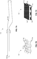
- FIG. 14 is a diagram 1400 that illustrates a cross-section view of another example of the aft portion 534 of the acoustic panel 132 of FIG. 3 .
- the doubler 816 and the cantilevered portion 144 include a joggle 1412 (e.g., a notch or faired in portion).
- the joggle 1412 provides a recessed portion 1414 (recessed surface) for coupling with another component to form an aerodynamic surface.
- the recessed portion 1414 provides for a smoother transition between an exterior surface of the cantilevered portion 144 and an exterior surface of the other component to which the cantilevered portion 144 is attached.
- no aerodynamic seal is used between the other component and the acoustic panel 132 or a size of an aerodynamic seal between the other component and the acoustic panel 132 is reduced.
- FIG. 15 is a diagram 1500 that illustrates a cross-section view of another example of the aft portion 534 of the acoustic panel 132 of FIG. 3 .
- the acoustic panel 132 of FIG. 15 has a molded insert 1512 for the support member 146.
- the molded insert 1512 includes or corresponds to a thermoplastic material or a thermoset polymer material.
- the molded insert 1512 is larger than the noodle 814 and extends further towards the distal end 834 than the noodle 814 of FIGS. 8 and 14 .
- the molded insert 1512 extends to the distal end 834 in the example illustrated in FIG. 15 , in other implementations the molded insert 1512 does not extend all the way to the distal end 834.
- the second layer of composite material 818 is larger (longer) and extends further towards the distal end 834 than the second layer of composite material 818 of FIG. 8 .
- the second layer of composite material 818 extends to the distal end 834 in the example illustrated in FIG. 15 , in other implementations, the second layer of composite material 818 does not extend all the way to the distal end 834.
- the pre-cured composite component 1216 (e.g., the doubler 816) is thinner than the pre-cured composite component 1216 (e.g., the doubler 816) of FIGS. 13 and 14 .
- the pre-cured composite component 1216 (e.g., the doubler 816) of FIG. 15 has a substantially constant cross-section and thickness (i.e., does not taper), as compared to the tapered pre-cured composite component 1216 (e.g., the doubler 816) of FIGS. 13 and 14 .
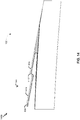
- FIG. 16 is a diagram 1600 that illustrates a cross-section view of another example of the aft portion 534 of the acoustic panel 132 of FIG. 3 .
- the acoustic panel 132 of FIG. 16 has a molded insert 1512 for the support member 146.
- the cantilevered portion 144 of the acoustic panel 132 of FIG. 16 is joggled.
- the acoustic panel 132 includes a joggle 1412 and a recessed receiving portion 1414, similar to the cantilevered portion 144 of the acoustic panel 132 of FIG. 14 .
- the second layer of composite material 818 is larger (longer) and extends further towards the distal end 834 than the second layer of composite material 818 of FIG. 8 .
- the second layer of composite material 818 extends to the distal end 834 in the example illustrated in FIG. 16 , in other implementations, the second layer of composite material 818 does not extend all the way to the distal end 834.
- the pre-cured composite component 1216 (e.g., the doubler 816) of FIG. 15 , the pre-cured composite component 1216 (e.g., the doubler 816) of FIG. 16 has a substantially constant cross-section and thickness (i.e., does not taper).
- the acoustic panels 132 of FIGS. 14-17 may be manufactured similar to the acoustic panel 132 of FIG. 8 , e.g., by one of more of the manufacturing stages illustrated in FIGS. 9-13 .
- the acoustic panels 132 of FIGS. 14-16 include adhesive 824, as described with reference to FIGS. 8 and 11 .
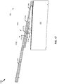
- FIG. 17 is a diagram 1700 that illustrates a cross-section view of an example coupling between the cantilevered portion 144 of the acoustic panel 132 of FIG. 3 and the transcowl 124 of FIG. 1 .
- a first coupling includes a first fastener assembly 1702 extending through the transcowl 124 and the cantilevered portion 144.
- the first fastener assembly 1702 includes a bolt 1712 and a nut 1714.
- the bolt 1712 and the nut 1714 include or correspond to flush head bolt and nut or a double-flush head bolt and nut.
- a technician (or two technicians) may require access to both the top surface and bottom surface (e.g., access to the gap 820) to fasten and unfasten (remove) the first fastener assembly 1702.
- a second coupling includes a second fastener assembly 1704, such as a nut plate 1724, rivets 1726, and the bolt 1712.
- the bolt 1712 extends through the transcowl 124 and the cantilevered portion 144.
- the nut plate 1724 is coupled to the cantilevered portion 144 by fasteners (e.g., the rivets 1726, screws, etc.) or adhesive or is fixed to the cantilevered portion 144 during curing.
- the transcowl 124 can be decoupled from the acoustic panel 132 without access to the gap 820.
- the transcowl 124 may be coupled to the cantilevered portion 144 using one or more first fastener assemblies 1702, one or more second fastener assemblies 1704, or a combination thereof.
- first fastener assembly 1702 is illustrated as extending through the middle of the cantilevered portion 144 (e.g., the doubler 816), the first fastener assembly 1702 (e.g., the bolt 1712 thereof) may extend through the proximal portion of the cantilevered portion (e.g., extend through the doubler 816 and the second layer of composite material 818).
- the cantilevered portion 144 includes the joggle 1412 and the transcowl 124 has a shape complementary to a shape of the joggle 1412 to form a smooth aerodynamic transition at an area 1732 near the joggle 1412.
- an aerodynamic filler is not utilized or a size of the aerodynamic filler is reduced.
- the aerodynamic transition is relatively smoother and imparts less drag than aerodynamic transitions between the transcowl 124 and cantilevered portion 144 without a joggle 1412, such as a cantilevered portion having a cross-section that is substantially straight or is straight in a longitudinal axis (e.g., fore to aft).
- the acoustic panel 132 is coupled to another component of a nacelle, a vehicle, or an aircraft, such as the aircraft 100 of FIG. 1 .
- FIG. 18 illustrates a particular example of a method 1800 for controlling generating an acoustic panel, such as the acoustic panel 132 of FIG. 1 .
- the method 1800 may be performed by computer (e.g., a controller of a composite part fabrication system).
- the method 1800 includes, at 1802, applying a layer of composite material to a base, the base having a surface defining a plurality of cavities.
- the layer of composite material may include or correspond to the first layer of composite material 812 of FIG. 8 or the second layer of composite material 818 of FIG. 8 .
- the base may include or correspond to the base 142 of FIG. 1 .
- the first layer of composite material 812 is deposited (e.g., directly deposited) on the base 142 or the second layer of composite material 818 is deposited on the base 142 and is in contact with the first layer of composite material 812.
- the method 1800 includes, at 1804, applying a layup support member to the layer of composite materials.
- the layup support member may include or correspond to the layup support member 1112 of FIG. 11 .
- the layup support member 1112 is placed on the base 142 (or the first layer of composite material 818) before curing (e.g., by a first cure or a second cure) the pre-cured composite component 1216 to the base 142, as described with reference to FIG. 12 .
- the method 1800 also includes, at 1806, forming a cantilevered portion extending from the base.
- the layup support material is positioned between the base and the cantilevered portion.
- the cantilevered portion is configured to be coupled to and support another component.
- a portion of a surface of the cantilevered portion is an aerodynamic surface, as described with reference to FIG. 8 .
- FIG. 18 illustrates two exemplary method of forming 1806 the cantilevered portion 144 in dashed boxes.
- forming 1806 includes applying 1812 second composite material to the layer of composite material and the layup support member.
- the layup support material is positioned between the base and the second composite material.
- the second composite material may include or correspond to uncured (e.g., "green") CFRP plies, as described with reference to FIG. 11 .
- the uncured CFRP plies are placed (laid-up) on the support material 1012 and the second layer of composite material 818 (which is supported by the layup support member 1112).
- forming 1806 also includes placing 1814 a caul plate on the second composite material and curing 1816 the layer of composite material and the second composite material to form the cantilevered portion.
- a caul plate is placed on top of the uncured CFRP plies. Heat and pressure are applied to the caul plate which transfers the heat and pressure to cure the uncured CFRP plies and one or more layers of composite material 812, 818 to form the cantilevered portion 144 and secure it to the base 142. After curing, the caul plate is removed.
- forming 1806 includes applying 1822 a pre-cured composite component to the layer of composite material and the layup support member to form a cantilevered portion extending from the base.
- the layup support member is positioned between the base and the cantilevered portion.
- the pre-cured composite component may include or correspond to the cantilevered portion 144 of FIG. 1 , the doubler 816 of FIG. 8 , the pre-cured composite component 1216 of FIG. 1 , or a combination thereof.
- the pre-cured composite component 1216 is placed on the layup support member 1112 and the support member 146 or the support material 1012, as described with reference to FIG. 12 .
- Curing one or more layers of composite material 812, 818 affixes the pre-cured composite component 1216 to the base 142 to form the doubler 816 which includes a portion that is attached to the base 142 (e.g., via the first layer of composite material 812) and a portion that extends from the base 142, i.e., the cantilevered portion 144.
- forming 1806 further includes curing 1824 the layer of composite material to fixedly couple the pre-cured composite component to the base. For example, heat and pressure is applied to cure the first layer of composite material 812, the second layer of composite material 818, or both, to fixedly adhere the pre-cured composite component 1216 to the base 142, as described with reference to FIG. 12 .
- Adhering the pre-cured composite component 1216 to the base 142 generates a cantilevered portion 144 for joining another component (e.g., a portion of the transcowl 124) and enlarges an active acoustic area of the base 142 (e.g., prevents reduction of an acoustically active area caused by fasteners joining the acoustic panel 132 and the other component).
- the acoustic panel 132 may be easily disconnected from the other component because of the use of fasteners not penetrating the base 142 (as opposed to adhesives, such as fasteners assemblies 1702, 1704) which improves repairability, aerodynamic performance, and acoustic performance (especially after repair or maintenance of the nacelle that requires disassembly to the acoustic panel 132 and the transcowl 124).
- the cantilevered portion is fixedly coupled or fixedly adhered to the base.
- the support member may be fixedly coupled or fixedly adhered to the base, the cantilevered portion, or both.
- the base 142, the cantilevered portion 144, and the support member 146 form a monolithic structure.
- one or more fasteners extend through the cantilevered portion and the portion of the transcowl to couple the cantilevered portion to the portion of the transcowl.
- one or more nut plates 1724 are fastened to the cantilevered portion 144, and the cantilevered portion 144 is joined with the portion of the transcowl 124 via bolts 1712 extending through the portion of the transcowl 124 and threading with the nut plate 1724.
- the plurality of cavities such as the plurality of cavities 722 of FIG. 7B , have a hexagonal shape (e.g., a honeycomb shape).
- the plurality of cavities has a circular shape, a rectangular shape, a square shape, a pentagonal shape, an octagonal shape, or a combination thereof, as described with reference to FIG. 7B .
- the cantilevered portion has a joggled portion to receive the portion of the transcowl.
- the cantilevered portion 144 is a joggled, notched, or faired in cantilevered portion 144 (e.g., includes the joggle 1412) and maintains aerodynamic smoothness when coupled with the transcowl 124, as illustrated in FIGS. 14 and 17 .
- the cantilevered portion 144 has a longitudinal cross-section that is substantially straight or is straight in a longitudinal axis (e.g., fore to aft), as illustrated in FIGS. 8 and 15 . Additional or alternatively, the cantilevered portion 144 is tapered, as illustrated in FIGS. 8 and 14 .
- the distal end 834 of the doubler 816 (or the pre-cured composite component 1216) is thicker than the proximal end 832 of the doubler 816 (or the pre-cured composite component 1216).
- the support member includes or corresponds to a noodle, such as the noodle 814 of FIGS. 8 and 14 .
- the noodle 814 includes or corresponds to a material having a similar elasticity to carbon fiber reinforced polymer of the cantilevered portion 144.
- the support member includes or corresponds to a molded insert, such as the molded insert 1512 of FIGS. 15 and 16 .
- the molded insert includes or corresponds to a thermoplastic material or a thermoset polymer material.
- the engine e.g., the propulsor 112
- the thrust reversal assembly e.g., the thrust reverser 116
- the thrust reversal assembly is configured to redirect a portion of the thrust generated by the engine to generate second thrust (and/or increase drag) that partially opposes the thrust, as described with reference to FIG. 1 .
- the method 1800 further includes removing the layup support member and inserting a support material into a cavity positioned between the layer of composite material and the cantilevered portion, as described with reference to FIGS. 10 and 13 .
- the method 1800 further includes applying a second layer of composite material to the layer of composite material, the support material, and the cantilevered portion and curing the second layer of composite material to couple the cantilevered portion (e.g., the pre-cured composite component), the support material, and the layer of composite material, as described with reference to FIGS. 11-13 .
- a second layer of composite material to the layer of composite material, the support material, and the cantilevered portion and curing the second layer of composite material to couple the cantilevered portion (e.g., the pre-cured composite component), the support material, and the layer of composite material, as described with reference to FIGS. 11-13 .
- the layer of composite material is applied to a first surface of the base.
- the method 1800 further includes applying a third layer of composite material to a second surface of the base.
- the second surface opposite the first surface and corresponding to a first aerodynamic surface.
- the first surface and a surface of the cantilevered portion correspond to a second aerodynamic surface, as described with reference to FIGS. 5 , 8 , and 9 .
- the method 1800 further includes, prior to applying the pre-cured composite component to the base applying carbon fiber reinforced polymer to a tool and curing (or partially curing) the carbon fiber reinforced polymer to generate the pre-cured composite component, as described with reference to FIG. 12 .
- the pre-cured composite component (or doubler) is tapered, as described with reference to FIG. 8 .
- the methods 1800 of FIG. 18 may be initiated or controlled by an application-specific integrated circuit (ASIC), a processing unit, such as a central processing unit (CPU), a controller, another hardware device, a firmware device, a field-programmable gate array (FPGA) device, or any combination thereof.
- ASIC application-specific integrated circuit
- the method 1800 of FIG. 18 can be initiated or controlled by one or more processors, such as one or more processors included in a control system.
- a portion of the method 1800 of FIG. 18 may be combined with a second portion of the method 1800 of FIG. 18 .
- one or more operations described with reference to FIG. 18 may be optional and/or may be performed in a different order than shown or described. Two or more operations described with reference to FIG. 18 may be performed at least partially concurrently.
- a vehicle produced by the vehicle manufacturing and service method 1900 of FIG. 19 may include an aircraft, an airship, a rocket, a satellite, a submarine, or another vehicle, as illustrative, non-limiting examples.
- the vehicle 2002 may be manned or unmanned (e.g., a drone or an unmanned aerial vehicle (UAV)).
- UAV unmanned aerial vehicle
- the exemplary method 1900 includes, at 1902, specification and design of a vehicle, such as a vehicle 2002 described with reference to FIG. 20 .
- the method 1900 may include specifying a design of an acoustic panel, such as the acoustic panel 132 of FIG. 1 .
- the method 1900 includes material procurement.
- the method 1900 may include procuring materials for the acoustic panel 132 of the vehicle 2002.
- the method 1900 includes, at 1906, component and subassembly manufacturing and, at 1908, system integration of the vehicle 2002.
- the method 1900 may include component and subassembly manufacturing (e.g., manufacturing the acoustic panel 132 of FIG. 1 ) of the vehicle 2002 and system integration (e.g., coupling the acoustic panel 132 of FIG. 1 to one or more components of the vehicle 2002, such as the transcowl 124).
- the method 1900 includes certification and delivery of the vehicle 2002 and, at 1912, placing the vehicle 2002 in service. Certification and delivery may include certifying the acoustic panel 132 of FIG. 1 by inspection or non-destructive testing.
- the vehicle 2002 While in service by a customer, the vehicle 2002 may be scheduled for routine maintenance and service (which may also include modification, reconfiguration, refurbishment, and so on).
- the method 1900 includes performing maintenance and service on the vehicle 2002.
- the method 1900 may include performing maintenance and service of the propulsor 112, the thrust reverser 116, or the acoustic panel 132 of FIG. 1 .
- maintenance and service of the propulsor 112 may include decoupling the acoustic panel 132 from the transcowl 124 or replacing the acoustic panel 132.
- Each of the processes of the method 1900 may be performed or carried out by a system integrator, a third party, and/or an operator (e.g., a customer).
- a system integrator may include without limitation any number of vehicle manufacturers and major-system subcontractors
- a third party may include without limitation any number of venders, subcontractors, and suppliers
- an operator may be an airline, leasing company, military entity, service organization, and so on.
- FIG. 20 a block diagram 2000 of an illustrative implementation of the vehicle 2002 that includes an acoustic panel, such as the acoustic panel 132 of FIG. 1 .
- the vehicle 2002 may include an aircraft, such as the aircraft 100 of FIG. 1 , as an illustrative, non-limiting example.
- the vehicle 2002 may have been produced by at least a portion of the method 1900 of FIG. 19 .
- the vehicle 2002 e.g., the aircraft 100 of FIG. 1
- the vehicle 2002 includes an airframe 2018, an interior 2022, the nacelle 102, and a plurality of systems 2020.
- the plurality of systems 2020 may include one or more of a propulsion system 2024, an electrical system 2026, an environmental system 2028, or a hydraulic system 2030.
- the nacelle 102 includes the acoustic panel 132, and the acoustic panel 132 includes the base 142, the cantilevered portion 144, and the support member 146.
- the acoustic panel 132 may be manufactured by one or more steps of the method 1800 of FIG. 18 and/or as described with reference to FIGS. 9-13 .
- Apparatus and methods included herein may be employed during any one or more of the stages of the method 1900 of FIG. 19 .
- components or subassemblies corresponding to production process 1908 may be fabricated or manufactured in a manner similar to components or subassemblies produced while the vehicle 2002 is in service, at 1912 for example and without limitation.
- one or more apparatus implementations, method implementations, or a combination thereof may be utilized during the production stages (e.g., stages 1902-1910 of the method 1900), for example, by substantially expediting assembly of or reducing the cost of the vehicle 2002.
- one or more of apparatus implementations, method implementations, or a combination thereof may be utilized while the vehicle 2002 is in service, at 1912 for example and without limitation, to maintenance and service, at 1914.
Landscapes
- Engineering & Computer Science (AREA)
- Chemical & Material Sciences (AREA)
- Combustion & Propulsion (AREA)
- Mechanical Engineering (AREA)
- General Engineering & Computer Science (AREA)
- Aviation & Aerospace Engineering (AREA)
- Soundproofing, Sound Blocking, And Sound Damping (AREA)
- Composite Materials (AREA)
- Moulding By Coating Moulds (AREA)
- Laminated Bodies (AREA)
Claims (15)
- Akustikpanel (132) für einen Schubumkehrer, mit:einer Basis (142), die eine Fläche (712, 714, 732, 734) aufweist, die eine Mehrzahl von Hohlräumen (722) definiert, die dazu konfiguriert sind, Lärm von einem Triebwerk zu dämpfen;einen ausladenden Abschnitt (144), der sich von der Basis (142) erstreckt und dazu konfiguriert ist, entfernbar, wenn in Benutzung, mit einem Abschnitt einer Übergangsverkleidung (124) gekoppelt zu sein;einer Lücke (820), die durch die Basis und den ausladenden Abschnitt (144) definiert ist; undeinem Stützelement (146), das mit dem ausladenden Abschnitt (144) gekoppelt ist und mit der Basis (142) gekoppelt ist, wobei das Stützelement (146) dazu konfiguriert ist, den ausladenden Abschnitt (144) stützen,einer ersten Schicht von Verbundwerkstoffmaterial (812), die mit zumindest einem Abschnitt der Basis (142) gekoppelt ist, wobei ein Abschnitt der ersten Schicht von Verbundwerkstoffmaterial (812) mit einem Abschnitt des ausladenden Abschnitts (144) gekoppelt ist, und wobei die erste Schicht des Verbundwerkstoffmaterials (812) zwischen der Basis (142) und dem ausladenden Abschnitt (144) angeordnet ist;einer zweiten Schicht von Verbundwerkstoffmaterial (818), die mit dem ausladenden Abschnitt (144), dem Stützelement (146), und der ersten Schicht von Verbundwerkstoffmaterial (812) gekoppelt ist;einem Klebstoff (824), der die zweite Schicht von Verbundwerkstoffmaterial (818) mit jedem von dem ausladenden Abschnitt (144), dem Stützelement (146), und der ersten Schicht von Verbundwerkstoffmaterial (812) koppelt.
- Akustikpanel (132) nach Anspruch 1, wobei die erste Schicht von Verbundwerkstoffmaterial (812) mit zumindest einem Abschnitt auf einer ersten Fläche (712) der Basis (142) gekoppelt ist, und des Weiteren mit einer dritten Schicht von Verbundwerkstoffmaterial (822), die mit zumindest einem Abschnitt einer zweiten Fläche (714) der Basis (1420) gekoppelt ist, wobei der mindestens eine Abschnitt von der ersten Fläche (712) und mindestens ein Abschnitt einer Fläche des ausladenden Abschnitts (144) einer ersten aerodynamischen Fläche (522) entsprechen, und wobei die zweite Fläche (714) entgegengesetzt zu der ersten Fläche (712) ist und einer zweiten aerodynamischen Fläche (524) entspricht.
- Akustikpanel (132) nach einem der Ansprüche 1-2, wobei der ausladende Abschnitt (144) einen gestauchten bzw. gestuften Abschnitt (1412) zum Aufnehmen des Abschnitts der Übergangsverkleidung (124) aufweist.
- Akustikpanel (132) nach einem der Ansprüche 1-3, wobei der ausladende Abschnitt (144) derart verjüngt (862) ist, dass ein Distalende (834) des ausladenden Abschnitts (144) dicker als ein Proximalende (832) des ausladenden Abschnitts (144) ist, und wobei das Distalende (834) des ausladenden Abschnitts (144) weiter von der Basis (142) als das Proximalende (832) ist.
- Akustikpanel (132) nach einem der Ansprüche 1-4, wobei das Stützelement (146) eine Nudel (814) aufweist, und wobei die Nudel (814) ein Material aufweist, das eine ähnliche Elastizität wie carbonfaserverstärktes Polymer des ausladenden Abschnitts (144) aufweist.
- Akustikpanel (132) nach einem der Ansprüche 1-4, wobei das Stützelement(146) einen geformten bzw. gespritzten Einsatz (1512) aufweist, und wobei der ausladende Abschnitt (144) eine im Wesentlichen konstante Dicke aufweist.
- Akustikpanel (132) nach Anspruch 6, wobei der geformte bzw. gespritzte Einsatz (1512) ein thermoplastisches oder duroplastisches Polymermaterial aufweist.
- Fahrzeug (100, 2002) mit:
einem Triebwerk (112); einer Triebwerksverkleidung (114, 122), die das Triebwerk teilweise umschließt; und einer Schubumkehrbaugruppe (116), die mit der Triebwerksverkleidung gekoppelt ist, wobei die Schubumkehrbaugruppe eine Übergangsverkleidung (124) und das Akustikpanel (132) gemäß einem der voranstehenden Ansprüche aufweist, das dazu konfiguriert ist, Lärm von dem Triebwerk zu dämpfen. - Fahrzeug (100, 2002) nach Anspruch 8, wobei das Triebwerk dazu konfiguriert ist, Schub zu erzeugen, und wobei die Schubumkehrbaugruppe dazu konfiguriert ist, einen Teil des durch das Triebwerk erzeugten Schubs umzurichten, um einen zweiten Schub zu erzeugen, der teilweise entgegengesetzt zu dem Schub ist.
- Fahrzeug (100, 2002) nach Anspruch 8, wobei die Triebwerksverkleidung und das Akustikpanel aerodynamische Flächen (522, 524) aufweisen, und wobei das Fahrzeug ein Luftfahrzeug ist, und wobei das Triebwerk und die Schubumkehrbaugruppe in einer Triebwerksgondel des Luftfahrzeugs vorhanden sind.
- Verfahren (1800) zum Herstellen eines Akustikpanels (132) nach einem der voranstehenden Ansprüche, wobei das Verfahren aufweist:Beaufschlagen (1802) einer ersten Schicht von Verbundwerkstoffmaterial (812) auf eine Basis (142), wobei die Basis (142) eine Fläche aufweist, die eine Mehrzahl von Hohlräumen (722) definiert;Beaufschlagen (1804) eines Schichtstützmaterials (1112) auf die erste Schicht von Verbundwerkstoffmaterial (812); undFormen (1806) eines ausladenden Abschnitts (144), der sich von der Basis (142) aus erstreckt, wobei das Schichtstützmaterial (1112) zwischen der Basis (142) und dem ausladenden Abschnitt (144) angeordnet ist, wobei das Formen des ausladenden Abschnitts (144) aufweist:- Beaufschlagen (1812) einer zweiten Schicht von Verbundwerkstoffmaterial (818) auf die erste Schicht von Verbundwerkstoffmaterial (812) und das Schichtlagenstützmaterial (1112);- Platzieren (1814) einer Druckplatte auf der zweiten Schicht von Verbundwerkstoffmaterial (818); und- Aushärten (1816) der ersten Schicht von Verbundwerkstoffmaterial (812) und der zweiten Schicht von Verbundwerkstoffmaterial (818), um den ausladenden Abschnitt (144) auszubilden,wobei nach dem Formen der ausladende Abschnitt (144) dazu konfiguriert ist, mit einer anderen Komponente gekoppelt zu sein und diese zu stützen, und wobei ein Abschnitt einer Fläche des ausladenden Abschnitts (144) eine aerodynamische Fläche aufweist.
- Verfahren nach Anspruch 11, wobei das Formen des ausladenden Abschnitts (144) aufweist:Beaufschlagen (1822) einer vorausgehärteten Verbundwerkstoffkomponente auf die erste Schicht von Verbundwerkstoffmaterial (812) und das Schichtlagenstützmaterial (1112), um den ausladenden Abschnitt (144) auszubilden; undAushärten (1824) der ersten Schicht von Verbundwerkstoffmaterial (812), um die vorausgehärteten Verbundwerkstoffkomponente fest mit der Basis (142) zu koppeln.
- Verfahren nach Anspruch 11, des Weiteren mit:vor dem Formen des ausladenden Abschnitts (144), Einfügen eines Stützmaterials (1012) in einen Hohlraum, der zwischen der Schicht von Verbundwerkstoffmaterial (812) und dem ausladenden Abschnitt (144) angeordnet ist; undnach dem Aushärten, Entfernen des Schichtlagenstützmaterials.
- Verfahren nach Anspruch 13, des Weiteren mit dem Beaufschlagen einer zweiten Schicht von Verbundwerkstoffmaterial (818) auf die Schicht von Verbundwerkstoffmaterial (812), das Stützmaterial und den ausladenden Abschnitt (144).
- Verfahren nach Anspruch 11, wobei die Schicht von Verbundwerkstoffmaterial (812) auf eine erste Fläche (712) der Basis (142) beaufschlagt ist, und des Weiteren mit dem Beaufschlagen einer dritten Schicht von Verbundwerkstoffmaterial (822) auf eine zweite Fläche (714) der Basis (142), wobei die erste Fläche und eine Fläche des ausladenden Abschnitts (144) einer ersten aerodynamischen Fläche (522) entsprechen, und wobei die zweite Fläche entgegengesetzt zu der ersten Fläche ist und einer zweiten aerodynamischen Fläche (524) entspricht.
Applications Claiming Priority (1)
| Application Number | Priority Date | Filing Date | Title |
|---|---|---|---|
| US16/023,512 US11047308B2 (en) | 2018-06-29 | 2018-06-29 | Acoustic panel for thrust reversers |
Publications (2)
| Publication Number | Publication Date |
|---|---|
| EP3587786A1 EP3587786A1 (de) | 2020-01-01 |
| EP3587786B1 true EP3587786B1 (de) | 2021-12-15 |
Family
ID=66685406
Family Applications (1)
| Application Number | Title | Priority Date | Filing Date |
|---|---|---|---|
| EP19177596.4A Active EP3587786B1 (de) | 2018-06-29 | 2019-05-31 | Akustikpaneel für schubumkehrvorrichtungen |
Country Status (3)
| Country | Link |
|---|---|
| US (1) | US11047308B2 (de) |
| EP (1) | EP3587786B1 (de) |
| CN (1) | CN110654527B (de) |
Families Citing this family (5)
| Publication number | Priority date | Publication date | Assignee | Title |
|---|---|---|---|---|
| FR3122904B1 (fr) * | 2021-05-17 | 2023-04-28 | Safran Nacelles | Inverseur de poussée à grilles mobiles, comprenant une structure arrière de support de grilles intégrant une fonction acoustique |
| FR3137133B1 (fr) * | 2022-06-22 | 2024-10-18 | Safran Nacelles | Volet de blocage d’un inverseur de poussée d’aéronef |
| FR3141681B1 (fr) * | 2022-11-09 | 2025-03-21 | Airbus Helicopters | Aéronef muni d’un conduit d’échappement couplé à un système de stabilisation |
| CN117227207A (zh) * | 2023-08-10 | 2023-12-15 | 湖北三江航天江北机械工程有限公司 | 带滑块类复合材料发动机壳体的成型方法 |
| CN117301572B (zh) * | 2023-11-02 | 2024-04-19 | 哈尔滨远驰航空装备有限公司 | 一种发动机内衬及其成型方法、模具 |
Family Cites Families (13)
| Publication number | Priority date | Publication date | Assignee | Title |
|---|---|---|---|---|
| US4826106A (en) | 1987-02-18 | 1989-05-02 | Grumman Aerospace Corporation | Advanced composite aircraft cowl |
| US6129311A (en) | 1997-07-30 | 2000-10-10 | The Boeing Company | Engine nacelle outer cowl panel with integral track fairings |
| EP0895223B1 (de) * | 1997-07-30 | 2003-04-16 | The Boeing Company | Akustikplatte für Motorgondel mit integrierte Keilverkleidung und Vorderring |
| US20010048048A1 (en) * | 1999-01-13 | 2001-12-06 | Brian L Riedel | Backside fitting attachment for nacelle acoustic panels |
| IT1318059B1 (it) * | 2000-06-28 | 2003-07-21 | Aermacchi S P A | Struttura fonoassorbente e di rinforzo per pannelli acustici digondole motore. |
| GB2395175B (en) | 2000-10-19 | 2005-01-05 | Short Brothers Plc | Aircraft propulsive power unit |
| US20100192590A1 (en) | 2009-01-30 | 2010-08-05 | Michael Robert Johnson | Thermally balanced materials |
| US9016040B2 (en) | 2012-11-30 | 2015-04-28 | General Electric Company | Thrust reverser system with translating-rotating cascade and method of operation |
| US9895840B2 (en) | 2014-05-15 | 2018-02-20 | The Boeing Company | Thermoformed cascades for jet engine thrust reversers |
| US10329009B2 (en) * | 2014-09-17 | 2019-06-25 | The Boeing Company | Composite wing edge attachment and method |
| US9902342B2 (en) * | 2015-05-28 | 2018-02-27 | Sabic Global Technologies B.V. | Bulkhead including a support structure and an acoustic component |
| US10738738B2 (en) * | 2016-06-17 | 2020-08-11 | Rohr, Inc. | Nacelle with bifurcation extension and integral structural reinforcement |
| US10794326B2 (en) * | 2016-08-29 | 2020-10-06 | The Boeing Company | Blocker door assembly having a thermoplastic blocker door for use in a turbine engine |
-
2018
- 2018-06-29 US US16/023,512 patent/US11047308B2/en active Active
-
2019
- 2019-05-31 EP EP19177596.4A patent/EP3587786B1/de active Active
- 2019-06-20 CN CN201910534590.9A patent/CN110654527B/zh active Active
Also Published As
| Publication number | Publication date |
|---|---|
| US11047308B2 (en) | 2021-06-29 |
| CN110654527A (zh) | 2020-01-07 |
| EP3587786A1 (de) | 2020-01-01 |
| US20200003124A1 (en) | 2020-01-02 |
| CN110654527B (zh) | 2024-03-15 |
Similar Documents
| Publication | Publication Date | Title |
|---|---|---|
| EP3587786B1 (de) | Akustikpaneel für schubumkehrvorrichtungen | |
| EP3594127B1 (de) | Aktives laminares durchflusskontrollsystem mit verbundplatte | |
| US9845769B2 (en) | Plastic core blocker door | |
| CN103826835B (zh) | 用于制造复合部件的包括净和脏部分的室 | |
| US20170259905A1 (en) | Mechanically Joining Airframe Members at Solid Insert | |
| EP3628586B1 (de) | Verteilerplattenanordnung für aktive laminarströmungssteuerung | |
| CN109834748B (zh) | 蜂窝芯材面板的结构重修 | |
| US10450054B2 (en) | Adhesively joining airframe members at solid insert | |
| US9410501B2 (en) | Translating sleeve actuation system and apparatus | |
| EP3584434B1 (de) | Schubumkehrkaskade und verfahren zur herstellung | |
| EP3628589B1 (de) | Strukturelle sammelkammerstütze für aktive laminarströmungssteuerung | |
| US20170259521A1 (en) | Large Cell Core Stiffened Panels with Solid Inserts | |
| US11022071B2 (en) | Load distribution panel assembly, system and method | |
| US20240110535A1 (en) | Thrust reverser cascade and method of manufacture | |
| US10800117B2 (en) | Method of forming an acoustic bond panel with insertable acoustic assemblies | |
| US11524770B2 (en) | Active laminar flow control plenum panel arrangements and installation methods | |
| EP3578790B1 (de) | Kaskadenanordnung für einen schubumkehrer eines strahltriebwerks | |
| CN114571825B (zh) | 用于复合结构的返工部件 | |
| US10240560B2 (en) | Boot for repair of chevron on nacelle | |
| US20200392923A1 (en) | Thrust reverser cascade and method of manufacture | |
| US20250382047A1 (en) | Composite panels with titanium ends | |
| JP2023130325A (ja) | 主翼に取り付けられるエンジン用のフェアリング |
Legal Events
| Date | Code | Title | Description |
|---|---|---|---|
| STAA | Information on the status of an ep patent application or granted ep patent |
Free format text: STATUS: EXAMINATION IS IN PROGRESS |
|
| PUAI | Public reference made under article 153(3) epc to a published international application that has entered the european phase |
Free format text: ORIGINAL CODE: 0009012 |
|
| 17P | Request for examination filed |
Effective date: 20190531 |
|
| AK | Designated contracting states |
Kind code of ref document: A1 Designated state(s): AL AT BE BG CH CY CZ DE DK EE ES FI FR GB GR HR HU IE IS IT LI LT LU LV MC MK MT NL NO PL PT RO RS SE SI SK SM TR |
|
| AX | Request for extension of the european patent |
Extension state: BA ME |
|
| 17Q | First examination report despatched |
Effective date: 20191205 |
|
| GRAP | Despatch of communication of intention to grant a patent |
Free format text: ORIGINAL CODE: EPIDOSNIGR1 |
|
| STAA | Information on the status of an ep patent application or granted ep patent |
Free format text: STATUS: GRANT OF PATENT IS INTENDED |
|
| RIC1 | Information provided on ipc code assigned before grant |
Ipc: F02K 1/82 20060101AFI20210624BHEP Ipc: F02K 1/72 20060101ALI20210624BHEP Ipc: F02C 7/24 20060101ALI20210624BHEP |
|
| INTG | Intention to grant announced |
Effective date: 20210726 |
|
| GRAJ | Information related to disapproval of communication of intention to grant by the applicant or resumption of examination proceedings by the epo deleted |
Free format text: ORIGINAL CODE: EPIDOSDIGR1 |
|
| STAA | Information on the status of an ep patent application or granted ep patent |
Free format text: STATUS: EXAMINATION IS IN PROGRESS |
|
| GRAP | Despatch of communication of intention to grant a patent |
Free format text: ORIGINAL CODE: EPIDOSNIGR1 |
|
| STAA | Information on the status of an ep patent application or granted ep patent |
Free format text: STATUS: GRANT OF PATENT IS INTENDED |
|
| GRAJ | Information related to disapproval of communication of intention to grant by the applicant or resumption of examination proceedings by the epo deleted |
Free format text: ORIGINAL CODE: EPIDOSDIGR1 |
|
| INTC | Intention to grant announced (deleted) | ||
| GRAP | Despatch of communication of intention to grant a patent |
Free format text: ORIGINAL CODE: EPIDOSNIGR1 |
|
| INTG | Intention to grant announced |
Effective date: 20210930 |
|
| INTG | Intention to grant announced |
Effective date: 20210930 |
|
| GRAS | Grant fee paid |
Free format text: ORIGINAL CODE: EPIDOSNIGR3 |
|
| INTG | Intention to grant announced |
Effective date: 20211012 |
|
| GRAA | (expected) grant |
Free format text: ORIGINAL CODE: 0009210 |
|
| STAA | Information on the status of an ep patent application or granted ep patent |
Free format text: STATUS: THE PATENT HAS BEEN GRANTED |
|
| INTG | Intention to grant announced |
Effective date: 20211018 |
|
| AK | Designated contracting states |
Kind code of ref document: B1 Designated state(s): AL AT BE BG CH CY CZ DE DK EE ES FI FR GB GR HR HU IE IS IT LI LT LU LV MC MK MT NL NO PL PT RO RS SE SI SK SM TR |
|
| REG | Reference to a national code |
Ref country code: GB Ref legal event code: FG4D Ref country code: CH Ref legal event code: EP |
|
| REG | Reference to a national code |
Ref country code: DE Ref legal event code: R096 Ref document number: 602019010017 Country of ref document: DE |
|
| REG | Reference to a national code |
Ref country code: IE Ref legal event code: FG4D |
|
| REG | Reference to a national code |
Ref country code: AT Ref legal event code: REF Ref document number: 1455664 Country of ref document: AT Kind code of ref document: T Effective date: 20220115 |
|
| REG | Reference to a national code |
Ref country code: LT Ref legal event code: MG9D |
|
| REG | Reference to a national code |
Ref country code: NL Ref legal event code: MP Effective date: 20211215 |
|
| PG25 | Lapsed in a contracting state [announced via postgrant information from national office to epo] |
Ref country code: RS Free format text: LAPSE BECAUSE OF FAILURE TO SUBMIT A TRANSLATION OF THE DESCRIPTION OR TO PAY THE FEE WITHIN THE PRESCRIBED TIME-LIMIT Effective date: 20211215 Ref country code: LT Free format text: LAPSE BECAUSE OF FAILURE TO SUBMIT A TRANSLATION OF THE DESCRIPTION OR TO PAY THE FEE WITHIN THE PRESCRIBED TIME-LIMIT Effective date: 20211215 Ref country code: FI Free format text: LAPSE BECAUSE OF FAILURE TO SUBMIT A TRANSLATION OF THE DESCRIPTION OR TO PAY THE FEE WITHIN THE PRESCRIBED TIME-LIMIT Effective date: 20211215 Ref country code: BG Free format text: LAPSE BECAUSE OF FAILURE TO SUBMIT A TRANSLATION OF THE DESCRIPTION OR TO PAY THE FEE WITHIN THE PRESCRIBED TIME-LIMIT Effective date: 20220315 |
|
| REG | Reference to a national code |
Ref country code: AT Ref legal event code: MK05 Ref document number: 1455664 Country of ref document: AT Kind code of ref document: T Effective date: 20211215 |
|
| PG25 | Lapsed in a contracting state [announced via postgrant information from national office to epo] |
Ref country code: SE Free format text: LAPSE BECAUSE OF FAILURE TO SUBMIT A TRANSLATION OF THE DESCRIPTION OR TO PAY THE FEE WITHIN THE PRESCRIBED TIME-LIMIT Effective date: 20211215 Ref country code: NO Free format text: LAPSE BECAUSE OF FAILURE TO SUBMIT A TRANSLATION OF THE DESCRIPTION OR TO PAY THE FEE WITHIN THE PRESCRIBED TIME-LIMIT Effective date: 20220315 Ref country code: LV Free format text: LAPSE BECAUSE OF FAILURE TO SUBMIT A TRANSLATION OF THE DESCRIPTION OR TO PAY THE FEE WITHIN THE PRESCRIBED TIME-LIMIT Effective date: 20211215 Ref country code: HR Free format text: LAPSE BECAUSE OF FAILURE TO SUBMIT A TRANSLATION OF THE DESCRIPTION OR TO PAY THE FEE WITHIN THE PRESCRIBED TIME-LIMIT Effective date: 20211215 Ref country code: GR Free format text: LAPSE BECAUSE OF FAILURE TO SUBMIT A TRANSLATION OF THE DESCRIPTION OR TO PAY THE FEE WITHIN THE PRESCRIBED TIME-LIMIT Effective date: 20220316 |
|
| PG25 | Lapsed in a contracting state [announced via postgrant information from national office to epo] |
Ref country code: NL Free format text: LAPSE BECAUSE OF FAILURE TO SUBMIT A TRANSLATION OF THE DESCRIPTION OR TO PAY THE FEE WITHIN THE PRESCRIBED TIME-LIMIT Effective date: 20211215 |
|
| PG25 | Lapsed in a contracting state [announced via postgrant information from national office to epo] |
Ref country code: SM Free format text: LAPSE BECAUSE OF FAILURE TO SUBMIT A TRANSLATION OF THE DESCRIPTION OR TO PAY THE FEE WITHIN THE PRESCRIBED TIME-LIMIT Effective date: 20211215 Ref country code: SK Free format text: LAPSE BECAUSE OF FAILURE TO SUBMIT A TRANSLATION OF THE DESCRIPTION OR TO PAY THE FEE WITHIN THE PRESCRIBED TIME-LIMIT Effective date: 20211215 Ref country code: RO Free format text: LAPSE BECAUSE OF FAILURE TO SUBMIT A TRANSLATION OF THE DESCRIPTION OR TO PAY THE FEE WITHIN THE PRESCRIBED TIME-LIMIT Effective date: 20211215 Ref country code: PT Free format text: LAPSE BECAUSE OF FAILURE TO SUBMIT A TRANSLATION OF THE DESCRIPTION OR TO PAY THE FEE WITHIN THE PRESCRIBED TIME-LIMIT Effective date: 20220418 Ref country code: ES Free format text: LAPSE BECAUSE OF FAILURE TO SUBMIT A TRANSLATION OF THE DESCRIPTION OR TO PAY THE FEE WITHIN THE PRESCRIBED TIME-LIMIT Effective date: 20211215 Ref country code: EE Free format text: LAPSE BECAUSE OF FAILURE TO SUBMIT A TRANSLATION OF THE DESCRIPTION OR TO PAY THE FEE WITHIN THE PRESCRIBED TIME-LIMIT Effective date: 20211215 Ref country code: CZ Free format text: LAPSE BECAUSE OF FAILURE TO SUBMIT A TRANSLATION OF THE DESCRIPTION OR TO PAY THE FEE WITHIN THE PRESCRIBED TIME-LIMIT Effective date: 20211215 |
|
| PG25 | Lapsed in a contracting state [announced via postgrant information from national office to epo] |
Ref country code: PL Free format text: LAPSE BECAUSE OF FAILURE TO SUBMIT A TRANSLATION OF THE DESCRIPTION OR TO PAY THE FEE WITHIN THE PRESCRIBED TIME-LIMIT Effective date: 20211215 Ref country code: AT Free format text: LAPSE BECAUSE OF FAILURE TO SUBMIT A TRANSLATION OF THE DESCRIPTION OR TO PAY THE FEE WITHIN THE PRESCRIBED TIME-LIMIT Effective date: 20211215 |
|
| REG | Reference to a national code |
Ref country code: DE Ref legal event code: R097 Ref document number: 602019010017 Country of ref document: DE |
|
| PG25 | Lapsed in a contracting state [announced via postgrant information from national office to epo] |
Ref country code: IS Free format text: LAPSE BECAUSE OF FAILURE TO SUBMIT A TRANSLATION OF THE DESCRIPTION OR TO PAY THE FEE WITHIN THE PRESCRIBED TIME-LIMIT Effective date: 20220415 |
|
| PLBE | No opposition filed within time limit |
Free format text: ORIGINAL CODE: 0009261 |
|
| STAA | Information on the status of an ep patent application or granted ep patent |
Free format text: STATUS: NO OPPOSITION FILED WITHIN TIME LIMIT |
|
| PG25 | Lapsed in a contracting state [announced via postgrant information from national office to epo] |
Ref country code: DK Free format text: LAPSE BECAUSE OF FAILURE TO SUBMIT A TRANSLATION OF THE DESCRIPTION OR TO PAY THE FEE WITHIN THE PRESCRIBED TIME-LIMIT Effective date: 20211215 Ref country code: AL Free format text: LAPSE BECAUSE OF FAILURE TO SUBMIT A TRANSLATION OF THE DESCRIPTION OR TO PAY THE FEE WITHIN THE PRESCRIBED TIME-LIMIT Effective date: 20211215 |
|
| 26N | No opposition filed |
Effective date: 20220916 |
|
| PG25 | Lapsed in a contracting state [announced via postgrant information from national office to epo] |
Ref country code: SI Free format text: LAPSE BECAUSE OF FAILURE TO SUBMIT A TRANSLATION OF THE DESCRIPTION OR TO PAY THE FEE WITHIN THE PRESCRIBED TIME-LIMIT Effective date: 20211215 |
|
| REG | Reference to a national code |
Ref country code: CH Ref legal event code: PL |
|
| REG | Reference to a national code |
Ref country code: BE Ref legal event code: MM Effective date: 20220531 |
|
| PG25 | Lapsed in a contracting state [announced via postgrant information from national office to epo] |
Ref country code: MC Free format text: LAPSE BECAUSE OF FAILURE TO SUBMIT A TRANSLATION OF THE DESCRIPTION OR TO PAY THE FEE WITHIN THE PRESCRIBED TIME-LIMIT Effective date: 20211215 Ref country code: LU Free format text: LAPSE BECAUSE OF NON-PAYMENT OF DUE FEES Effective date: 20220531 Ref country code: LI Free format text: LAPSE BECAUSE OF NON-PAYMENT OF DUE FEES Effective date: 20220531 Ref country code: CH Free format text: LAPSE BECAUSE OF NON-PAYMENT OF DUE FEES Effective date: 20220531 |
|
| PG25 | Lapsed in a contracting state [announced via postgrant information from national office to epo] |
Ref country code: IE Free format text: LAPSE BECAUSE OF NON-PAYMENT OF DUE FEES Effective date: 20220531 |
|
| PG25 | Lapsed in a contracting state [announced via postgrant information from national office to epo] |
Ref country code: IT Free format text: LAPSE BECAUSE OF FAILURE TO SUBMIT A TRANSLATION OF THE DESCRIPTION OR TO PAY THE FEE WITHIN THE PRESCRIBED TIME-LIMIT Effective date: 20211215 Ref country code: BE Free format text: LAPSE BECAUSE OF NON-PAYMENT OF DUE FEES Effective date: 20220531 |
|
| P01 | Opt-out of the competence of the unified patent court (upc) registered |
Effective date: 20230516 |
|
| PG25 | Lapsed in a contracting state [announced via postgrant information from national office to epo] |
Ref country code: MK Free format text: LAPSE BECAUSE OF FAILURE TO SUBMIT A TRANSLATION OF THE DESCRIPTION OR TO PAY THE FEE WITHIN THE PRESCRIBED TIME-LIMIT Effective date: 20211215 Ref country code: CY Free format text: LAPSE BECAUSE OF FAILURE TO SUBMIT A TRANSLATION OF THE DESCRIPTION OR TO PAY THE FEE WITHIN THE PRESCRIBED TIME-LIMIT Effective date: 20211215 |
|
| PG25 | Lapsed in a contracting state [announced via postgrant information from national office to epo] |
Ref country code: HU Free format text: LAPSE BECAUSE OF FAILURE TO SUBMIT A TRANSLATION OF THE DESCRIPTION OR TO PAY THE FEE WITHIN THE PRESCRIBED TIME-LIMIT; INVALID AB INITIO Effective date: 20190531 |
|
| PG25 | Lapsed in a contracting state [announced via postgrant information from national office to epo] |
Ref country code: TR Free format text: LAPSE BECAUSE OF FAILURE TO SUBMIT A TRANSLATION OF THE DESCRIPTION OR TO PAY THE FEE WITHIN THE PRESCRIBED TIME-LIMIT Effective date: 20211215 |
|
| PG25 | Lapsed in a contracting state [announced via postgrant information from national office to epo] |
Ref country code: MT Free format text: LAPSE BECAUSE OF FAILURE TO SUBMIT A TRANSLATION OF THE DESCRIPTION OR TO PAY THE FEE WITHIN THE PRESCRIBED TIME-LIMIT Effective date: 20211215 |
|
| PGFP | Annual fee paid to national office [announced via postgrant information from national office to epo] |
Ref country code: DE Payment date: 20250529 Year of fee payment: 7 |
|
| PGFP | Annual fee paid to national office [announced via postgrant information from national office to epo] |
Ref country code: GB Payment date: 20250527 Year of fee payment: 7 |
|
| PGFP | Annual fee paid to national office [announced via postgrant information from national office to epo] |
Ref country code: FR Payment date: 20250526 Year of fee payment: 7 |