EP3587715A1 - A method and a system for unlocking a hood of a vehicle - Google Patents
A method and a system for unlocking a hood of a vehicle Download PDFInfo
- Publication number
- EP3587715A1 EP3587715A1 EP18179893.5A EP18179893A EP3587715A1 EP 3587715 A1 EP3587715 A1 EP 3587715A1 EP 18179893 A EP18179893 A EP 18179893A EP 3587715 A1 EP3587715 A1 EP 3587715A1
- Authority
- EP
- European Patent Office
- Prior art keywords
- hood
- safety catch
- latch
- vehicle
- striker
- Prior art date
- Legal status (The legal status is an assumption and is not a legal conclusion. Google has not performed a legal analysis and makes no representation as to the accuracy of the status listed.)
- Granted
Links
Images



Classifications
-
- E—FIXED CONSTRUCTIONS
- E05—LOCKS; KEYS; WINDOW OR DOOR FITTINGS; SAFES
- E05B—LOCKS; ACCESSORIES THEREFOR; HANDCUFFS
- E05B83/00—Vehicle locks specially adapted for particular types of wing or vehicle
- E05B83/16—Locks for luggage compartments, car boot lids or car bonnets
- E05B83/24—Locks for luggage compartments, car boot lids or car bonnets for car bonnets
- E05B83/243—Hood clamps, i.e. individually actuated, usually yielding hooks
-
- E—FIXED CONSTRUCTIONS
- E05—LOCKS; KEYS; WINDOW OR DOOR FITTINGS; SAFES
- E05B—LOCKS; ACCESSORIES THEREFOR; HANDCUFFS
- E05B77/00—Vehicle locks characterised by special functions or purposes
- E05B77/54—Automatic securing or unlocking of bolts triggered by certain vehicle parameters, e.g. exceeding a speed threshold
-
- B—PERFORMING OPERATIONS; TRANSPORTING
- B62—LAND VEHICLES FOR TRAVELLING OTHERWISE THAN ON RAILS
- B62D—MOTOR VEHICLES; TRAILERS
- B62D25/00—Superstructure or monocoque structure sub-units; Parts or details thereof not otherwise provided for
- B62D25/08—Front or rear portions
- B62D25/10—Bonnets or lids, e.g. for trucks, tractors, busses, work vehicles
- B62D25/12—Parts or details thereof
-
- E—FIXED CONSTRUCTIONS
- E05—LOCKS; KEYS; WINDOW OR DOOR FITTINGS; SAFES
- E05B—LOCKS; ACCESSORIES THEREFOR; HANDCUFFS
- E05B81/00—Power-actuated vehicle locks
- E05B81/54—Electrical circuits
- E05B81/64—Monitoring or sensing, e.g. by using switches or sensors
- E05B81/66—Monitoring or sensing, e.g. by using switches or sensors the bolt position, i.e. the latching status
- E05B81/68—Monitoring or sensing, e.g. by using switches or sensors the bolt position, i.e. the latching status by sensing the position of the detent
-
- E—FIXED CONSTRUCTIONS
- E05—LOCKS; KEYS; WINDOW OR DOOR FITTINGS; SAFES
- E05B—LOCKS; ACCESSORIES THEREFOR; HANDCUFFS
- E05B83/00—Vehicle locks specially adapted for particular types of wing or vehicle
- E05B83/16—Locks for luggage compartments, car boot lids or car bonnets
- E05B83/24—Locks for luggage compartments, car boot lids or car bonnets for car bonnets
-
- E—FIXED CONSTRUCTIONS
- E05—LOCKS; KEYS; WINDOW OR DOOR FITTINGS; SAFES
- E05B—LOCKS; ACCESSORIES THEREFOR; HANDCUFFS
- E05B79/00—Mounting or connecting vehicle locks or parts thereof
- E05B79/10—Connections between movable lock parts
- E05B79/20—Connections between movable lock parts using flexible connections, e.g. Bowden cables
-
- E—FIXED CONSTRUCTIONS
- E05—LOCKS; KEYS; WINDOW OR DOOR FITTINGS; SAFES
- E05B—LOCKS; ACCESSORIES THEREFOR; HANDCUFFS
- E05B81/00—Power-actuated vehicle locks
- E05B81/02—Power-actuated vehicle locks characterised by the type of actuators used
- E05B81/04—Electrical
- E05B81/08—Electrical using electromagnets or solenoids
-
- E—FIXED CONSTRUCTIONS
- E05—LOCKS; KEYS; WINDOW OR DOOR FITTINGS; SAFES
- E05B—LOCKS; ACCESSORIES THEREFOR; HANDCUFFS
- E05B85/00—Details of vehicle locks not provided for in groups E05B77/00 - E05B83/00
- E05B85/20—Bolts or detents
- E05B85/24—Bolts rotating about an axis
- E05B85/26—Cooperation between bolts and detents
Definitions
- the present disclosure relates to a method for unlocking a hood of a vehicle, wherein a hood locking mechanism comprises a latch, a safety catch, a locking member, and a striker; wherein the latch and the safety catch are arranged for engaging the striker and the locking member is arranged for engaging the safety catch.
- the disclosure further relates to a system for unlocking a hood, and a vehicle having a system for unlocking a hood.
- Single-pull hood latch systems are opening a hood locking mechanism from a fully locked mode to an intermediate locked mode through a single-pull action from the user.
- the hood locking mechanism is opened to the intermediate locked mode.
- a manual action from the user is required, and often a safety catch arranged in connection to the hood locking mechanism at the front section of the car must be released to open the hood. Since with the single-pull system the user is required to release the safety catch manually, the opening operation is many times inconvenient and complicated, and there is also a risk that the user's hands or clothes are getting soiled.
- Double-pull hood latch systems are opening the hood locking mechanism from the fully locked mode to the open mode through a double-pull action from the user.
- the hood locking mechanism is opened from the fully locked mode to the intermediate locked mode.
- the opening handle needs to be released and then pulled again in a second sequence to move the hood locking mechanism from the intermediate locked mode to the open mode.
- the double-pull system the user is not required to release a safety catch arranged at the front section of the car, which simplifies the opening of the hood, and further eliminates the need for manually opening the hood in front of the car, which many times are complicated and risking that the user's hands or clothes are getting soiled.
- the double-pull systems are considered to provide a more simplified opening of the hood with a premium feeling compared to the single-pull systems. However, since double-pull systems are not constructed with a safety catch, they are considered to be less safe in accidents or crash situations. The dual-pull action is also considered to be an inconvenient way of opening the hood.
- An object of the present disclosure is to provide a method for unlocking a hood of the vehicle, a system for unlocking a hood, and a vehicle having a system for unlocking a hood, where the previously mentioned problems are avoided.
- This object is at least partly achieved by the features of the independent claims.
- the dependent claims contain further developments of the method for unlocking the hood of a vehicle.
- a hood locking mechanism comprises a latch, a safety catch, a locking member, and a striker.
- the latch and the safety catch are arranged for engaging the striker and the locking member is arranged for engaging the safety catch.
- the method comprises the steps; manually displacing a door of the vehicle, wherein the door in a closed position is blocking an inner hood handle, from the closed position to an open position in a fully locked mode of the hood locking mechanism for giving access to the inner hood handle; manually activating the inner hood handle for moving the hood locking mechanism from the fully locked mode to an intermediate locked mode, wherein the activation of the inner hood handle mechanically is displacing the latch from a closed position where the latch is in locking engagement with the striker to an open position where the latch is disengaged from the striker; triggering a sensor by the latch, when the latch is displaced to the open position, wherein an electrical signal from the sensor is activating the locking member after a predetermined time interval if at least one predetermined vehicle condition is fulfilled, where upon activation, the locking member is displaced from a first position where the locking member is in locking engagement with the safety catch to a second position where the locking member is disengaged from the safety catch; displacing the safety catch if the at least
- the method is providing a simple way for unlocking the hood of the vehicle with only a single-pull action, where the method is convenient to the user of the vehicle and fulfils the safety regulations.
- a solution that is not requiring double manual operation from the user is achieved with the same safety level as with traditional single-pull systems, since the system is equipped with a safety catch.
- the user is with the method not required to open the hood at the front section of the car and with only a single-pull action at least the same premium feeling as with a double-pull system is achieved.
- the method is providing a more convenient opening of the hood compared to both the single-pull systems and the double-pull systems used today.
- the latch and the safety catch are in locking engagement with the striker, and the locking member is in locking engagement with the safety catch.
- the intermediate locked mode the latch is disengaged from the striker, the safety catch is in locking engagement with the striker, and the locking member is in locking engagement with the safety catch.
- the open mode the latch and the safety catch are disengaged from the striker, and the locking member is disengaged from the safety catch.
- the intermediate locking mode is configured so that the system cannot move the hood locking mechanism to the open mode unless the predetermined vehicle conditions are fulfilled, as described above.
- both the latch and the safety catch are securing that the striker is engaged and that the hood is not opened, which for example could happen in a crash situation or accident.
- the safety catch is engaging the striker preventing that the hood is further opened, for example if an accident occurs.
- the at least one predetermined vehicle condition is a standstill position of the vehicle, an open position of a vehicle driver door, an activated position of a parking brake, and/or a parking position of a transmission of the vehicle.
- the predetermined vehicle conditions are used to secure that the hood is opened only in safe vehicle situations.
- the predetermined vehicle conditions are one or more prerequisites that needs to be fulfilled before it is possible to open the hood.
- the prerequisites a standstill position of the vehicle, an activated position of a parking brake, and/or a parking position of a transmission of the vehicle are securing that the vehicle is not moving when opening the hood.
- the prerequisite open position of a vehicle driver door can be used to secure that the user of the vehicle actively is performing a conscious action, and could especially be used in combination with the one or more other conditions where the vehicle is in a standstill position.
- the at least one predetermined vehicle condition is a determination if a user is standing in front of the vehicle, and the determination if the user is standing in front of the vehicle is established through key position recognition and/or biometric recognition.
- This condition could be used to secure that the user of the vehicle is actively taking action and is standing in front of the vehicle before the hood is opened, and could especially be used in combination with the one or more other conditions where the vehicle is in a standstill position. Also with this prerequisite, the user of the vehicle is actively performing a conscious action.
- the locking member is electrically displaced from the first position to the second position.
- the system can be designed to automatically unlock the hood without any interaction from the user of the vehicle, which is providing a simple and efficient opening of the hood.
- the system may be designed so that the locking member is mechanically displaced from the second position to the first position during a closing operation of the hood.
- the safety catch in the open state is blocking the locking member, preventing the locking member from being displaced from the second position to the first position. This feature is preventing that the locking member is repositioned to the first position when the safety catch is in the open state.
- the blocking function is used to secure that the locking member can be repositioned only when the safety catch is in the closed state and when returning to the first position, the locking member is engaging the safety catch preventing the safety catch to move to the open state.
- the predetermined time interval is in the range 1-30 seconds.
- the time interval is chosen so that a relevant level of safety is met with the method, and any time interval between 1-30 second is possible to use.
- a suitable time interval could for example be dependent on safety regulations or legislations.
- the hood locking mechanism is a single-pull action hood unlocking mechanism, wherein the manual activation of the inner hood handle is a single-pull action, releasing the hood of the vehicle from the from the fully locked mode to the intermediate locked mode.
- the single-pull action mechanism is a simple and easy-to-use method for the user of the vehicle.
- the single-pull activation of the hood locking mechanism according to the disclosure is providing a method where only one opening action is required by the user if the at least one predetermined vehicle condition is fulfilled, since the system automatically will unlock the hood locking mechanism once the single pull action is completed.
- the locking member is a solenoid comprising a plunger, which plunger when activated is electrically displaced from the first position to the second position, and when not activated through spring action is held in the first position.
- Solenoids are simple in construction and also reliable.
- the spring action is used for repositioning the locking member from the second position to the first position and also to hold the locking mechanism in the first position.
- the safety catch when the locking member is disengaged from the safety catch, is displaced from the closed state to the open state through spring action.
- the spring activation of the safety catch is a simple and reliable constructional design that is moving or repositioning the safety catch from the closed state to the open state.
- the safety catch is free to move to the open state.
- the method further comprises the steps; activating a notification signal when the latch is displaced to the open position; and/or when the safety catch is displaced to the open state.
- the notification signal is indicating to the user that the latch and/or the safety catch has been repositioned and the notification signal is used for a convenient and safe unlocking procedure of the hood.
- the notification signal is a visual indication in the vehicle and/or in an external device; and/or an audial indication in the vehicle and/or in an external device.
- a visual and/or an audial indication in the vehicle is a simple and efficient way to notify the user.
- the vehicle is then equipped with suitable notification means for the visual and/or audial notification.
- a signal could also be sent to an external device, such as a mobile phone, and visually and/or audibly notify the user via the external device.
- the method further comprises the step; activating a visual and/or an audial warning signal if the vehicle is moving when the latch is in the open position and/or when the safety catch is in the open state.
- This is an important safety feature that is securing that the vehicle cannot move without a warning signal being sent out if the hood locking mechanism is in the intermediate locked mode or in the open mode. The user is thus notified to avoid accidents.
- the hood locking mechanism is moved from the intermediate locked mode to the fully locked mode if the at least one predetermined vehicle condition is not fulfilled after the predetermined time interval. This is further increasing the safety of the system, since with this function the hood can be automatically closed if the at least one predetermined vehicle condition is not fulfilled after the predetermined time interval.
- the disclosure further concerns a system for unlocking a hood of a vehicle, and a vehicle having a system for unlocking a hood, where the system is including a hood locking mechanism comprising a latch, a safety catch, a locking member, and a striker.
- the latch and the safety catch are arranged for engaging the striker and the locking member is arranged for engaging the safety catch.
- a door of the vehicle in a closed position is blocking an inner hood handle, wherein the door is arranged for giving access to the inner hood handle when the door is manually displaced from the closed position to an open position in a fully locked mode of the hood locking mechanism.
- the inner hood handle is arranged for moving the hood locking mechanism from the fully locked mode to an intermediate locked mode through manual activation, wherein the activation of the inner hood handle mechanically is displacing the latch from a closed position where the latch is in locking engagement with the striker to an open position where the latch is disengaged from the striker.
- a sensor is arranged for being triggered by the latch, when the latch is displaced to the open position, wherein an electrical signal from the sensor is activating the locking member after a predetermined time interval if at least one predetermined vehicle condition is fulfilled, where upon activation, the locking member is configured to being displaced from a first position wherein the locking member is in locking engagement with the safety catch to a second position where the locking member is disengaged from the safety catch.
- the safety catch is arranged for being displaced from a closed state where the safety catch is in locking engagement with the striker to an open state where the safety catch is disengaged from the striker for moving the hood locking mechanism from the intermediate locked mode to an open mode.
- the hood unlocking system is providing a simple way for unlocking the hood of the vehicle with only a single-pull action, which gives a premium feeling to the user of the vehicle.
- a solution that is not requiring double manual operation from the user is achieved with the same safety level as with traditional single-pull systems, since the system is equipped with a safety catch.
- the system is further convenient to use and fulfils the safety regulations, and the user is with the hood unlocking system not required to open the hood at the front section of the car. Therefore, the system is providing a more convenient opening of the hood compared to both the single-pull systems and the double-pull systems used today.
- FIG. 1 schematically shows a vehicle with a system for unlocking a hood 1 of the vehicle, where a hood locking mechanism 2 is used for unlocking the hood 1.
- the hood 1 of the vehicle needs to be opened by a user of the vehicle, or by other persons, such as service technicians, that are having access to the vehicle.
- the hood 1 is designed so that during driving the hood 1 is firmly closed by the hood locking mechanism 2.
- the hood locking mechanism 2 is preventing that the hood 1 is unintentionally opened during driving. In crash situations or accidents, the hood 1 should remain in its closed position to avoid unnecessary injuries or damage and therefore the hood locking mechanism 2 is made in a robust construction.
- the hood locking mechanism 2 comprises a latch 3, a safety catch 4, a locking member 5, and a striker 6.
- the striker 6 is attached to the hood 1 of the vehicle and the striker 6 is arranged to interact with the latch 3 and the safety catch 4.
- the latch 6 may be of any suitable construction and is following the hood 1 when the hood 1 is moved between a closed position and an open position.
- the latch 3, the safety catch 4 and the locking member 5 are arranged in connection to each other in a front section of the vehicle and may as an example be integrated in a front frame structure 14 positioned below the hood 1, as illustrated in figure 1 .
- the latch 3 and the safety catch 4 may for example be arranged in a conventional way in a lock housing structure or similar arrangement to form a locking unit that is attached to the front frame structure 14.
- the latch 3 and the safety catch 4 are arranged for engaging the striker 6 and the locking member 5 is arranged for engaging the safety catch 4, as will be further described below.
- the hood locking mechanism 2 is designed to be arranged in three different modes, where the striker 6 is having different positions in relation to the latch 3 and/or the safety catch 4 in the different modes.
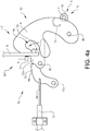
- the hood locking mechanism 2 is moving from a fully locked mode M1, as shown in figure 4a , to an open mode M3, as shown in figure 4c .
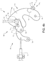
- the hood locking mechanism 2 is having an intermediate locked mode M2 between the fully locked mode M1 and the open mode M3 to prevent unintentional opening of the hood, as shown in figure 4b .
- the three different modes are providing a safe hood locking and unlocking system, and the hood 1 is opened from the fully locked mode M1 to the open mode M3 in two different steps.
- the intermediate locked mode M2 is securing that the hood 1 is not fully opened in only one step which could cause accidents if the hood 1 is opened unintentionally, for example during driving.
- the intermediate locking mode M2 is thus configured so that the system cannot move the hood locking mechanism 2 directly from the fully locked mode M1 to the open mode M3.
- both the latch 3 and the safety catch 4 are securing that the striker 6 is engaged and that the hood 1 cannot be opened.
- the safety catch 4 is engaging the striker 6 preventing that the hood 1 is being further opened.
- the hood unlocking system and the method for unlocking the hood 1 is designed to provide a simple way for unlocking the hood 1 of the vehicle, where the method is convenient to the user of the vehicle and fulfils the safety regulations.
- the system is configured as a single-pull action unlocking mechanism, and with the method, a solution that is not requiring double manual operation from the user is achieved with the same safety level as with traditional single-pull systems.
- the user is with the system and method not required to open the hood 1 at the front section of the car as with traditional single-pull systems, and with only a single-pull action at least the same premium feeling as with a traditional double-pull system is achieved.
- the method is providing a more convenient opening of the hood compared to both the single-pull systems and the double-pull systems used today.
- FIG 4a the fully locked mode M1 of the hood locking mechanism 2 is shown.
- the latch 3 and the safety catch 4 are in locking engagement with the striker 6, preventing that the hood 1 is being opened.
- the latch 3 is provided with a latch slot 3a that is holding the striker 6 in a locked position.
- the safety catch 4 is provided with a safety catch slot 4a that is arranged to catch the striker 6 if the latch 3 is unintentionally unlocked, for example if a malfunction of the latch 3 occurs.
- the striker 6 is arranged inside the safety catch slot 4a and the safety catch 4 is thus in locking engagement with the striker 6.
- FIG 4b the intermediate locked mode M2 of the hood locking mechanism 2 is shown.
- the latch 3 is disengaged from the striker 6, and the safety catch 4 is in locking engagement with the striker 6, preventing that the hood 1 is being opened.
- the striker 6 is released from the latch slot 3a, and the safety catch slot 4a of the safety catch 4 is engaging the striker 6 in the intermediate locked mode M2.
- the striker 6 is arranged inside the safety catch slot 4a and the safety catch 4 is thus in locking engagement with the striker 6.
- FIG 4c the open mode M3 of the hood locking mechanism 2 is shown.
- the latch 3 and the safety catch 4 are disengaged from the striker 6, allowing the hood 1 to be opened.
- the striker 6 is released from the latch slot 3a, and also from the safety catch slot 4a.
- the latch 3 is arranged to being displaced from a closed position P C in the fully locked mode M1, as shown in figure 4a , to an open position P O in the intermediate locked mode M2 and in the open mode M3, as shown in figures 4b and 4c .
- the latch 3 In the closed position P C the latch 3 is in locking engagement with the striker 6, and in the open position P O the latch 3 is disengaged from the striker 6.
- the latch 3 is configured so that it can pivot or rotate around a latch axis 3b, between the open position P O and the closed position P C .
- the latch axis 3b may for example be attached to the lock housing structure and the latch 3 is rotatably arranged around the latch axis 3b in relation to the lock housing structure.
- a pawl 12 is arranged to hold the latch 3 in the closed position P C
- the pawl 12 in the embodiment shown is arranged with a pawl locking surface 12a that is in contact with the latch 3 in the locked position, preventing that the latch 3 can rotate around the latch axis 3a to the open position P O
- the pawl 12 is configured so that it can rotate around a pawl axis 12b between a locked configuration, as shown in figure 4a , where the pawl locking surface 12a is in locking engagement with the latch 3, and an unlocked configuration, as shown in figures 4b and 4c , where the pawl 12 is disengaged from the latch 3.
- the pawl locking surface 12a may be arranged on a suitable part of the pawl 12 and is designed to interact with the latch 3 so that the latch 3 cannot move when the pawl 12 is in engagement with the latch 3.
- the pawl axis 12b may for example be attached to the lock housing structure and the pawl 12 is rotatably arranged around the pawl axis 12b in relation to the lock housing structure.
- the pawl 12 can be connected to a release member, such as a Bowden cable 13 connected to an inner hood handle 8, which is moving the pawl 12 from the locked configuration to the unlocked configuration through activation by a user of the vehicle.
- the pawl 12 may be provided with a return arrangement to move the pawl 12 from the unlocked configuration back to the locked configuration.
- a compression spring, an extension spring, a torsion spring, or other suitable mechanism may be used as the return arrangement for the pawl 12.
- the latch 3 may be provided with a repositioning arrangement to move the latch 3 from the closed position P C to the open position P O when the pawl 12 is disengaged from the latch 3.
- a compression spring, an extension spring, a torsion spring, or other suitable mechanism may be used as the repositioning arrangement for the latch 3.
- a sensor 9 may be arranged in connection to the latch 3, and the sensor 9 is configured to be triggered by the latch 3 when the latch 3 is displaced to the open position P O .
- the sensor 9 may be of any suitable configuration, for example a position detection sensor, a magnetic sensor, a laser sensor or an electrical switch, such as a micro switch, that is activated when the latch 3 is in the open position P O .
- the sensor 9 is used for detecting that the latch 3 is in the open position P O and the sensor 9 is sending a signal to a control unit used for controlling the hood locking system.
- the control unit may be a processing device, such as a CPU that is directing the operation of a processor and used for controlling and steering the operation of the hood locking mechanism 2.
- the safety catch 4 is arranged to being displaced from a closed state S C in the fully locked mode M1 and in the intermediate locked mode M2, as shown in figures 4a and 4b , to an open state S O in the open mode M3, as shown in figure 4c .
- the closed state S C the safety catch 4 is in locking engagement with the striker 6 and in the open state S O the safety catch 4 is disengaged from the striker 6.
- the safety catch 4 is configured so that it can pivot or rotate around a safety catch axis 4b, between the closed state S C and the open state S O .
- the safety catch axis 4b may for example be attached to the lock housing structure and the safety catch 4 is rotatably arranged around the safety catch axis 4b in relation to the lock housing structure.
- a locking member 5 is arranged to hold the safety catch 4 in the closed state S C .
- the locking member 5 In the fully locked mode M1 and in the intermediate locked mode M2, as shown in figures 4a and 4b , the locking member 5 is in locking engagement with the safety catch 4.
- the locking member 5 In the open mode M3, the locking member 5 is disengaged from the safety catch 4, as shown in figure 4c .
- the locking member in the embodiment shown in the figures is a solenoid 10, comprising a movable plunger 11.
- the solenoid 10 may be of any suitable design and construction known in the art, and is converting electrical energy into linear motion.
- the solenoid 10 comprises a coil of wire, and when a current is applied to the coil a magnetic field generated by the coil is moving the plunger 11 through the electromagnetic force generated, from an extended first position P 1 to a retracted second position P 2 .
- the plunger 11 is being moved from the retracted second position P 2 to the extended first position P 1 through spring action, where a spring mechanism arranged in the solenoid 10 in a conventional way is pushing the plunger to the extended first position P1.
- the solenoid 10 when being electrically activated, is displacing the plunger 11 from the first position P 1 , as shown in figures 3 , 4a and 4b where the locking member 5 is in locking engagement with the safety catch 4 to the second position P 2 , as shown in figure 4c , where the locking member 5 is disengaged from the safety catch 4.
- the solenoid 10 When the solenoid 10 is not activated, the plunger 11 is, as described above, through spring action held in the first position P 1 . In the first position P 1 , the plunger 11 is in the extended state and is preventing the safety catch 4 from moving through direct contact with the safety catch 4.
- the locking member 5 is electrically displaced from the first position P 1 to the second position P 2 , and the plunger 11 when activated is electrically displaced from the first position P 1 to the second position P 2 .
- the plunger 11 is through spring action held in the first position P 1 .
- the control unit When the control unit is receiving the signal from the sensor 9 indicating that the latch 3 is in the open position P O , the control unit is starting the calculation of the predetermined time interval T. After the predetermined time interval T, the control unit is activating the locking member 5, wherein the locking member 5 is being displaced to the second position P 2 if certain conditions are fulfilled, as will be further described below.
- the safety catch 4 can be provided with a repositioning arrangement to move the safety catch 4 from the closed state S C to the open state S O when the locking member 5 is disengaged from the safety catch 4.
- a compression spring, an extension spring, a torsion spring, or other suitable mechanism may be used as the repositioning arrangement for the safety catch 4.
- the safety catch 4 when the locking member 5 is disengaged from the safety catch 4, is displaced from the closed state S C to the open state S O through spring action.
- the locking member may comprise a stopping member 15 preventing further movement of the safety catch 4, as shown in figure 4c .
- the stopping member 15 can for example be arranged as a protrusion that is engaging a part of the locking member 5 in the open state S O .
- the safety catch 4 is in the open state S O blocking the locking member 5, preventing that the locking member 5 is being displaced from the second position P 2 to the first position P 1 .
- the plunger 11 is blocked by the body of the safety catch 4 through the position of the safety catch 4 in the open state S O .
- the solenoid 10 only needs to be activated until the safety catch 4 has been moved from the closed state S C to the open state S O .
- the plunger 11 is prevented from moving to the second position through spring action since the safety catch 4 is blocking the movement of the plunger 11.
- the plunger 11 is free to move to the first position P1 through spring action when the safety catch 4 has been moved to the closed state S C .
- electric power only needs to be supplied to the solenoid 10 until the safety catch 4 has been moved to the open state S O , which provides an energy efficient solution minimizing the energy consumption of the system.
- the plunger 11 When the solenoid is activated, the plunger 11 is being displaced from the first position P 1 to the second position P 2 . In the second position P 2 , the plunger 11 is in the retracted state and is allowing the safety catch 4 to move from the closed state S C to the open state S O through spring action. Thus, in the second position P 2 , the locking member 5 is no longer blocking the movement of the safety catch 4, wherein the safety catch 4, when the locking member 5 is disengaged from the safety catch 4, is displaced from the closed state S C to the open state S O through spring action.
- the plunger 11 may be provided with a rounded head or similar arrangement so that the safety catch 4 easily can move past the plunger 11 to the open state S O .
- the user should manually displace the latch 3 from the closed position P C to the open position P O .
- the user is displacing the pawl 12 from the locked configuration to the unlocked configuration via the inner hood handle 8 arranged within the interior structure of the vehicle.
- the inner hood handle 8 is connected to the pawl 12 with the Bowden cable 13 and when pulling the inner hood handle 8, the Bowden cable 13 is displacing the pawl 12 from the locked configuration to the unlocked configuration.
- the pawl 12 is displaced by a single-pull action by the user and when the pawl 12 is displaced into the unlocked configuration, the latch 3 is allowed to move from the closed position P C to the open position P O , since the pawl 12 is disengaged from the latch 3.
- the inner hood handle 8 may be of any suitable construction known in the art, such as for example a pivoting or translating handle arranged to displace the pawl 12 via the Bowden cable 13.
- FIGS 2a and 2b an interior structure of the vehicle is shown.
- a door 7 of the vehicle is shown in a closed position, and in figure 2b the door 7 is shown in an open position.
- the inner hood handle 8 is arranged in relation to the door 7 so that at least a part of a door structure of the door 7 is preventing opening of the inner hood handle 8 when the door 7 is in the closed position.
- the door 7 according to the disclosure may be any of the side doors of the vehicle, but normally the inner hood handle 8 is arranged in relation to the driver's side door.
- the door 7 may be configured in a way where the door structure, such as for example a part of a door frame or a part of a door panel, in the closed position is covering at least a part of the inner hood handle 8 preventing access to the inner hood handle 8.
- the door 7 in the closed position is blocking the displacement or activation of the inner hood handle 8 preventing that the inner hood handle can be used for opening the hood 1.
- This design of the door 7 in relation to the inner hood handle 8 is used for preventing that the inner hood handle 8 can be used for opening the hood 1 when the door 7 is in the closed position.
- the user In order to open the hood 1, the user must open the door 7 and thereafter displace or activate the inner hood handle 8 to open the hood 1.
- the purpose with this arrangement is to further increase the safety of the method and system.
- the steps described below need to be executed in relation to the hood unlocking system and the hood locking mechanism 2.
- the hood locking mechanism comprises the latch 3, the safety catch 4, the locking member 5, and the striker 6.
- the latch and the safety catch are arranged for engaging the striker and the locking member is arranged for engaging the safety catch.
- the door 7 of the vehicle is manually displaced from the closed position to the open position for giving access to the inner hood handle 8, where the door 7 in the closed position is blocking the inner hood handle 8.
- the user of the vehicle is thus manually opening the door 7 to get access to the inner hood handle 8.
- the hood handle 8 is blocked by the door 7 and therefore the opening of the door 7 is required in order to get access to the inner hood handle 8.
- getting access to the inner hood handle 8 is meant that the user in a consecutive step should have the possibility to displace or activate the inner hood handle.
- the inner hood handle 8 is manually activated for moving the hood locking mechanism 2 from the fully locked mode M1 to the intermediate locked mode M2.
- the activation of the inner hood handle 8 is mechanically displacing the latch 3 from the closed position P C where the latch 3 is in locking engagement with the striker 6 to the open position P O where the latch 3 is disengaged from the striker 6.
- the pawl 12 is moved to the unlocked configuration through the interaction with the inner hood handle 8 via the Bowden cable 13.
- the latch 3 When the pawl 12 is in the unlocked configuration, the latch 3 is as described above displaced from the closed position P C to the open position P O through spring action, where in the open position P O the latch 3 is disengaged from the striker 6. Through the disengagement of the striker 6, the system is in the intermediate locking mode M2.
- the sensor 9 is triggered by the latch 3, when the latch 3 is displaced to the open position P O .
- An electrical signal from the sensor 9 is activating the locking member 5 after a predetermined time interval T if at least one predetermined vehicle condition is fulfilled, where upon activation, the locking member 5 is displaced from the first position P 1 where the locking member 5 is in locking engagement with the safety catch 4 to the second position P 2 where the locking member 5 is disengaged from the safety catch 4.
- the control unit may for example be used to determine if the at least one predetermined vehicle condition is fulfilled.
- the predetermined vehicle conditions are used for further increasing the safety of the system, as will be further described below, and unless the at least one predetermined vehicle condition is fulfilled the locking member 5 will not be activated and displaced to the second position P 2 where the locking member 5 is disengaged from the safety catch 4. Thus, if the at least one predetermined vehicle condition is not fulfilled, the locking member 5 will remain in the first position P 1 where the locking member 5 is in locking engagement with the safety catch 4.
- the predetermined time interval T is chosen to secure that a high level of safety of the system is achieved with the method, which is ensuring that the at least one predetermined vehicle condition is fulfilled after the predetermined time interval T.
- the predetermined time interval T may be in the range of 1-30 seconds.
- a suitable predetermined time interval T may for example be dependent on safety regulations or legislations.
- the safety catch 4 is displaced from the closed state S C where the safety catch 4 is in locking engagement with the striker 6 to the open state S O where the safety catch 4 is disengaged from the striker 6.
- the hood locking mechanism 2 is moved from the intermediate locked mode M2 to the open mode M3.
- the striker 6 is fully disengaged from both the latch 3 and the safety catch 4 and the user can move the hood 1 to an open position if desired.
- the safety catch 4 is displaced from the closed state S C to the open state S O through spring action, where in the open state S O the safety catch 4 is disengaged from the striker 6.
- the at least one predetermined vehicle condition can be a standstill position of the vehicle, an open position of a vehicle driver door, an activated position of a parking brake, and/or a parking position of a transmission of the vehicle, and thus the predetermined vehicle conditions are one or more prerequisites that needs to be fulfilled before it is possible to open the hood 1. If the one or more predetermined vehicle conditions are not fulfilled, the system will refuse a continued unlocking of the hood 1. The evaluation if the predetermined vehicle conditions are fulfilled can be done by the control unit. Since the one or more predetermined vehicle conditions can be used as prerequisites for a continued hood unlocking process, the predetermined vehicle conditions are securing that the hood 1 is opened only in safe vehicle situations.
- the prerequisites a standstill position of the vehicle, an activated position of a parking brake, and/or a parking position of a transmission of the vehicle is securing that the vehicle is not moving when opening the hood 1.
- the prerequisite open position of a vehicle driver door can be used to secure that the user of the vehicle actively is performing a conscious action, and could especially be used in combination with another of the conditions where the vehicle is in a standstill position.
- the at least one predetermined vehicle condition can also be a determination if a user is standing in front of the vehicle.
- the determination if the user is standing in front of the vehicle can for example be established through key position recognition and/or biometric recognition.
- the vehicle can for example with known systems be designed to recognize or detect if the vehicle key is in a position if front of the vehicle.
- the vehicle may be equipped with a biometric sensor that is recognising if the user is positioned in front of the vehicle.
- the biometric sensor may for example be a face recognition sensor that is detecting the face of the user. Other types of suitable biometric sensors may also be used, such as fingerprint sensors, hand detection sensors or eye detection sensors.
- This prerequisite may be used to secure that the user of the vehicle is actively taking action and is standing in front of the vehicle before the hood is opened.
- the user of the vehicle must actively perform a conscious action before the hood 1 can be unlocked.
- the condition if a user is standing in front of the vehicle could especially be used in combination with another of the conditions where the vehicle is in a standstill position.
- the safety level of the system can easily be modified through the at least one predetermined vehicle condition.
- the safety level can be specifically designed for the vehicle, or be modified for example if safety regulations are changing.
- Other predetermined vehicle conditions than the ones described above may also be used.
- the disclosed hood locking mechanism 2 is a single-pull action hood unlocking mechanism.
- the manual activation of the inner hood handle 8 is a single-pull action that is releasing the hood 1 of the vehicle from the fully locked mode M1 to the intermediate locked mode M2.
- the system will automatically perform the necessary actions, provided that the at least one predetermined vehicle conditions is fulfilled.
- the user of the vehicle needs to secure that the prerequisites for unlocking the hood are fulfilled and thereafter through the single-pull action activate the system.
- the system is further providing an energy efficient solution, where the components involved only need to be supplied with electrical power during activation or displacement.
- the system and method may further comprise an activation of a notification signal when the latch 3 is displaced to the open position P O , and/or when the safety catch 4 is displaced to the open state S O .
- a notification signal an indication is given to the user that the latch and/or the safety catch has been repositioned, and the notification signal is used for a convenient and safe unlocking procedure of the hood 1.
- the notification signal may as an example be a visual indication in the vehicle and/or in an external device.
- the notification signal may be an audial indication in the vehicle and/or in an external device.
- a visual indication or an audial indication in the vehicle is a simple and efficient way to notify the user.
- the vehicle may be equipped with suitable notification means for the visual and/or audial notification, such as a display or a loudspeaker.
- suitable notification means for the visual and/or audial notification such as a display or a loudspeaker.
- the displays and sound systems already present in the vehicle may be used for notifying the user.
- a signal could also be sent to an external device, such as a mobile phone, and visually and/or audibly notify the user via the external device that the latch 3 is displaced to the open position P O , and/or that the safety catch 4 is displaced to the open state S O .
- the system and method may further comprise an activation of a visual and/or an audial warning signal if the vehicle is moving when the latch 3 is in the open position P O and/or when the safety catch 4 is in the open state S O .
- This is an important safety feature that is securing that the vehicle cannot move without a warning signal being sent out if the hood locking mechanism 2 is in the intermediate locked mode M2 or in the open mode M3.
- the user is notified in an efficient way with the warning signal, which may prevent accidents.
- the warning signal may in the same way as with the notification signal described above be a visual indication in the vehicle and/or in an external device.
- the warning signal may be an audial indication in the vehicle and/or in an external device.
- the vehicle may be equipped with suitable warning means for the visual and/or audial warning signal, such as a display or a loudspeaker.
- suitable warning means for the visual and/or audial warning signal such as a display or a loudspeaker.
- the displays and sound systems already present in the vehicle may be used for warning the user that the vehicle is moving when the latch 3 is in the open position P O , and/or when the safety catch 4 is in the open state S O .
- a signal could also be sent to an external device, such as a mobile phone, and visually and/or audibly notify the user via the external device.
- the system for unlocking the hood 1 of the vehicle comprises the hood locking mechanism 2 comprising the latch 3, the safety catch 4, the locking member 5, and the striker 6, where the latch 3 and the safety catch 4 are arranged for engaging the striker 6 and the locking member 5 is arranged for engaging the safety catch 4.
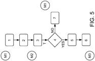
- the unlocking sequence of the hood locking mechanism 2 is schematically shown.
- the door 7 of the vehicle is in the closed position blocking the inner hood handle 8, and the door 7 is arranged for giving access to the inner hood handle 8 when the door 7 is manually displaced from the closed position to the open position in the fully locked mode M1 of the hood locking mechanism 2.
- Step 1 in the unlocking sequence in figure 5 is corresponding to the manual displacement of the door 7 from the closed position to the open position for giving access to the inner hood handle 8.
- the inner hood handle 8 is arranged for moving the hood locking mechanism 2 from the fully locked mode M1 to an intermediate locked mode M2 through manual activation.
- the manual activation of the inner hood handle 8 is mechanically displacing the latch 3 from the closed position P C where the latch 3 is in locking engagement with the striker 6 to the open position P O where the latch 3 is disengaged from the striker 6, and this sequence is corresponding to step 2 in figure 5 .
- the hood locking mechanism 2 has been moved from the fully locked mode M1 to the intermediate locked mode M2.
- the sensor 9 is arranged for being triggered by the latch 3 when the latch 3 is displaced to the open position P O , and an electrical signal from the sensor 9 is activating the locking member 5 after the predetermined time interval T if the at least one predetermined vehicle condition is fulfilled.
- the triggering of the sensor 9 is illustrated in figure 5 as step 3.
- step 4 shown in figure 5 it is determined if the at least one predetermined vehicle condition is fulfilled, and the predetermined time interval T must be completed before the system is moving from step 3 to step 4. If the at least one predetermined condition is fulfilled, the locking member 5 is being activated in step 5 in figure 5 .
- the locking member 5 Upon activation, the locking member 5 is configured to being displaced from the first position P 1 wherein the locking member 5 is in locking engagement with the safety catch 4 to the second position P 2 where the locking member 5 is disengaged from the safety catch 4.
- the safety catch 4 is being displaced for moving the hood locking mechanism 2 from the intermediate locked mode M2 to the open mode M3.
- the safety catch 4 is arranged for being displaced from the closed state S C where the safety catch 4 is in locking engagement with the striker 6 to the open state S O where the safety catch 4 is disengaged from the striker 6 for moving the hood locking mechanism 2 from the intermediate locked mode M2 to the open mode M3.
- the hood is simply manually displaced by the user in a closing direction of the hood 1, which normally is in a downwards direction.
- the striker 6 is engaging the safety catch 4 so that the safety catch 4 is moving from the open state S O to the closed state S C .
- the locking member 5 is being displaced to the first position P 1 from the second position P 2 through spring action, since the safety catch 4 is no longer blocking the plunger 11.
- the striker 6 is engaging the latch 3 so that the latch is displaced from the open position P O to the closed position P C .
- the closing of the hood 1 is in this way a mechanical operation without the need for electric power.
- the system and method could automatically activate the hood locking mechanism 2 so that the hood 1 is moved from the intermediate locked mode M2 to the fully locked mode M1, which is illustrated as step 7 in figure 5 .
- This may for example be accomplished by an actuating mechanism that is pulling the hood 1 in the closing direction from the intermediate locked mode M2 to the fully locked mode M1.
- the actuating mechanism could for example be arranged as a separate actuator that is connected to the hood 1 and to the vehicle front frame structure 14.
- the latch 3 can be connected to an electric motor that is rotating the latch 3 from the open position P O to the closed position P C , and with this arrangement the latch 3 is pulling the striker 6 with the rotational motion so that the hood 1 is moving in the closing direction for closing the hood 1.
- the electric motor could be directly or indirectly connected to for example the latch axis 3b for rotating the latch 3 from the open position P O to the closed position P C .
- the control unit can be used for determining if the predetermined vehicle condition is not fulfilled after the predetermined time interval T, and the control unit could initiate the automated closing action of the hood 1 as described above.
Landscapes
- Engineering & Computer Science (AREA)
- Physics & Mathematics (AREA)
- Electromagnetism (AREA)
- Chemical & Material Sciences (AREA)
- Combustion & Propulsion (AREA)
- Transportation (AREA)
- Mechanical Engineering (AREA)
- Lock And Its Accessories (AREA)
Abstract
Description
- The present disclosure relates to a method for unlocking a hood of a vehicle, wherein a hood locking mechanism comprises a latch, a safety catch, a locking member, and a striker; wherein the latch and the safety catch are arranged for engaging the striker and the locking member is arranged for engaging the safety catch. The disclosure further relates to a system for unlocking a hood, and a vehicle having a system for unlocking a hood.
- There are mainly two different systems and methods for unlocking vehicle hoods, such as car hoods, that are used on today's vehicles on the market. Due to safety regulations, the systems use a two-step opening process, where the hood is opened through a double action from a user of the vehicle. There are mainly two different systems on the market, the single-pull hood latch system and the double-pull latch system.
- Single-pull hood latch systems are opening a hood locking mechanism from a fully locked mode to an intermediate locked mode through a single-pull action from the user. When the user is pulling an opening handle arranged in the interior structure of the car, the hood locking mechanism is opened to the intermediate locked mode. To further move the hood locking mechanism into an open mode, a manual action from the user is required, and often a safety catch arranged in connection to the hood locking mechanism at the front section of the car must be released to open the hood. Since with the single-pull system the user is required to release the safety catch manually, the opening operation is many times inconvenient and complicated, and there is also a risk that the user's hands or clothes are getting soiled.
- Double-pull hood latch systems are opening the hood locking mechanism from the fully locked mode to the open mode through a double-pull action from the user. When the user is pulling the opening handle in a first sequence, the hood locking mechanism is opened from the fully locked mode to the intermediate locked mode. Thereafter, the opening handle needs to be released and then pulled again in a second sequence to move the hood locking mechanism from the intermediate locked mode to the open mode. With the double-pull system the user is not required to release a safety catch arranged at the front section of the car, which simplifies the opening of the hood, and further eliminates the need for manually opening the hood in front of the car, which many times are complicated and risking that the user's hands or clothes are getting soiled. The double-pull systems are considered to provide a more simplified opening of the hood with a premium feeling compared to the single-pull systems. However, since double-pull systems are not constructed with a safety catch, they are considered to be less safe in accidents or crash situations. The dual-pull action is also considered to be an inconvenient way of opening the hood.
- There is thus a need for an improved hood opening system and method where the opening system fulfils the safety regulations, has the same safety level as the single-pull systems with the premium feeling of the double-pull systems, but with a more convenient opening procedure as with the two systems used today.
- An object of the present disclosure is to provide a method for unlocking a hood of the vehicle, a system for unlocking a hood, and a vehicle having a system for unlocking a hood, where the previously mentioned problems are avoided. This object is at least partly achieved by the features of the independent claims. The dependent claims contain further developments of the method for unlocking the hood of a vehicle.
- The disclosure concerns a method for unlocking a hood of a vehicle, wherein a hood locking mechanism comprises a latch, a safety catch, a locking member, and a striker. The latch and the safety catch are arranged for engaging the striker and the locking member is arranged for engaging the safety catch. The method comprises the steps; manually displacing a door of the vehicle, wherein the door in a closed position is blocking an inner hood handle, from the closed position to an open position in a fully locked mode of the hood locking mechanism for giving access to the inner hood handle; manually activating the inner hood handle for moving the hood locking mechanism from the fully locked mode to an intermediate locked mode, wherein the activation of the inner hood handle mechanically is displacing the latch from a closed position where the latch is in locking engagement with the striker to an open position where the latch is disengaged from the striker; triggering a sensor by the latch, when the latch is displaced to the open position, wherein an electrical signal from the sensor is activating the locking member after a predetermined time interval if at least one predetermined vehicle condition is fulfilled, where upon activation, the locking member is displaced from a first position where the locking member is in locking engagement with the safety catch to a second position where the locking member is disengaged from the safety catch; displacing the safety catch if the at least one predetermined vehicle condition is fulfilled from a closed state wherein the safety catch is in locking engagement with the striker to an open state where the safety catch is disengaged from the striker for moving the hood locking mechanism from the intermediate locked mode to an open mode.
- The method is providing a simple way for unlocking the hood of the vehicle with only a single-pull action, where the method is convenient to the user of the vehicle and fulfils the safety regulations. With the method, a solution that is not requiring double manual operation from the user is achieved with the same safety level as with traditional single-pull systems, since the system is equipped with a safety catch. The user is with the method not required to open the hood at the front section of the car and with only a single-pull action at least the same premium feeling as with a double-pull system is achieved. Further, the method is providing a more convenient opening of the hood compared to both the single-pull systems and the double-pull systems used today.
- According to an aspect of the disclosure, in the fully locked mode, the latch and the safety catch are in locking engagement with the striker, and the locking member is in locking engagement with the safety catch. In the intermediate locked mode, the latch is disengaged from the striker, the safety catch is in locking engagement with the striker, and the locking member is in locking engagement with the safety catch. In the open mode, the latch and the safety catch are disengaged from the striker, and the locking member is disengaged from the safety catch. The three different modes are providing a safe system, where the hood is opened in two different steps. The intermediate locked mode is securing that the hood is not directly fully opened which could cause accidents if opened unintentionally, for example during driving. The intermediate locking mode is configured so that the system cannot move the hood locking mechanism to the open mode unless the predetermined vehicle conditions are fulfilled, as described above. In the fully locked mode both the latch and the safety catch are securing that the striker is engaged and that the hood is not opened, which for example could happen in a crash situation or accident. In the intermediate locked mode, the safety catch is engaging the striker preventing that the hood is further opened, for example if an accident occurs.
- According to another aspect of the disclosure, the at least one predetermined vehicle condition is a standstill position of the vehicle, an open position of a vehicle driver door, an activated position of a parking brake, and/or a parking position of a transmission of the vehicle. The predetermined vehicle conditions are used to secure that the hood is opened only in safe vehicle situations. The predetermined vehicle conditions are one or more prerequisites that needs to be fulfilled before it is possible to open the hood. The prerequisites a standstill position of the vehicle, an activated position of a parking brake, and/or a parking position of a transmission of the vehicle are securing that the vehicle is not moving when opening the hood. The prerequisite open position of a vehicle driver door can be used to secure that the user of the vehicle actively is performing a conscious action, and could especially be used in combination with the one or more other conditions where the vehicle is in a standstill position.
- According to other aspects of the disclosure, the at least one predetermined vehicle condition is a determination if a user is standing in front of the vehicle, and the determination if the user is standing in front of the vehicle is established through key position recognition and/or biometric recognition. This condition could be used to secure that the user of the vehicle is actively taking action and is standing in front of the vehicle before the hood is opened, and could especially be used in combination with the one or more other conditions where the vehicle is in a standstill position. Also with this prerequisite, the user of the vehicle is actively performing a conscious action.
- According to an aspect of the disclosure, the locking member is electrically displaced from the first position to the second position. Through electrical displacement, the system can be designed to automatically unlock the hood without any interaction from the user of the vehicle, which is providing a simple and efficient opening of the hood. However, the system may be designed so that the locking member is mechanically displaced from the second position to the first position during a closing operation of the hood.
- According to a further aspect of the disclosure, the safety catch in the open state is blocking the locking member, preventing the locking member from being displaced from the second position to the first position. This feature is preventing that the locking member is repositioned to the first position when the safety catch is in the open state. The blocking function is used to secure that the locking member can be repositioned only when the safety catch is in the closed state and when returning to the first position, the locking member is engaging the safety catch preventing the safety catch to move to the open state.
- According to an aspect of the disclosure, the predetermined time interval is in the range 1-30 seconds. The time interval is chosen so that a relevant level of safety is met with the method, and any time interval between 1-30 second is possible to use. A suitable time interval could for example be dependent on safety regulations or legislations.
- According to another aspect of the disclosure, the hood locking mechanism is a single-pull action hood unlocking mechanism, wherein the manual activation of the inner hood handle is a single-pull action, releasing the hood of the vehicle from the from the fully locked mode to the intermediate locked mode. The single-pull action mechanism is a simple and easy-to-use method for the user of the vehicle. The single-pull activation of the hood locking mechanism according to the disclosure is providing a method where only one opening action is required by the user if the at least one predetermined vehicle condition is fulfilled, since the system automatically will unlock the hood locking mechanism once the single pull action is completed.
- According to a further aspect of the disclosure, the locking member is a solenoid comprising a plunger, which plunger when activated is electrically displaced from the first position to the second position, and when not activated through spring action is held in the first position. Solenoids are simple in construction and also reliable. The spring action is used for repositioning the locking member from the second position to the first position and also to hold the locking mechanism in the first position.
- According to an aspect of the disclosure, the safety catch, when the locking member is disengaged from the safety catch, is displaced from the closed state to the open state through spring action. The spring activation of the safety catch is a simple and reliable constructional design that is moving or repositioning the safety catch from the closed state to the open state. When the locking member is disengaged from the safety catch the safety catch is free to move to the open state.
- According to another aspect of the disclosure, the method further comprises the steps; activating a notification signal when the latch is displaced to the open position; and/or when the safety catch is displaced to the open state. The notification signal is indicating to the user that the latch and/or the safety catch has been repositioned and the notification signal is used for a convenient and safe unlocking procedure of the hood.
- According to a further aspect of the disclosure, the notification signal is a visual indication in the vehicle and/or in an external device; and/or an audial indication in the vehicle and/or in an external device. A visual and/or an audial indication in the vehicle is a simple and efficient way to notify the user. The vehicle is then equipped with suitable notification means for the visual and/or audial notification. A signal could also be sent to an external device, such as a mobile phone, and visually and/or audibly notify the user via the external device.
- According to an aspect of the disclosure, the method further comprises the step; activating a visual and/or an audial warning signal if the vehicle is moving when the latch is in the open position and/or when the safety catch is in the open state. This is an important safety feature that is securing that the vehicle cannot move without a warning signal being sent out if the hood locking mechanism is in the intermediate locked mode or in the open mode. The user is thus notified to avoid accidents.
- According to an aspect of the disclosure, the hood locking mechanism is moved from the intermediate locked mode to the fully locked mode if the at least one predetermined vehicle condition is not fulfilled after the predetermined time interval. This is further increasing the safety of the system, since with this function the hood can be automatically closed if the at least one predetermined vehicle condition is not fulfilled after the predetermined time interval.
- The disclosure further concerns a system for unlocking a hood of a vehicle, and a vehicle having a system for unlocking a hood, where the system is including a hood locking mechanism comprising a latch, a safety catch, a locking member, and a striker. The latch and the safety catch are arranged for engaging the striker and the locking member is arranged for engaging the safety catch. A door of the vehicle in a closed position is blocking an inner hood handle, wherein the door is arranged for giving access to the inner hood handle when the door is manually displaced from the closed position to an open position in a fully locked mode of the hood locking mechanism. The inner hood handle is arranged for moving the hood locking mechanism from the fully locked mode to an intermediate locked mode through manual activation, wherein the activation of the inner hood handle mechanically is displacing the latch from a closed position where the latch is in locking engagement with the striker to an open position where the latch is disengaged from the striker. A sensor is arranged for being triggered by the latch, when the latch is displaced to the open position, wherein an electrical signal from the sensor is activating the locking member after a predetermined time interval if at least one predetermined vehicle condition is fulfilled, where upon activation, the locking member is configured to being displaced from a first position wherein the locking member is in locking engagement with the safety catch to a second position where the locking member is disengaged from the safety catch. The safety catch is arranged for being displaced from a closed state where the safety catch is in locking engagement with the striker to an open state where the safety catch is disengaged from the striker for moving the hood locking mechanism from the intermediate locked mode to an open mode.
- The hood unlocking system is providing a simple way for unlocking the hood of the vehicle with only a single-pull action, which gives a premium feeling to the user of the vehicle. With the system, a solution that is not requiring double manual operation from the user is achieved with the same safety level as with traditional single-pull systems, since the system is equipped with a safety catch. The system is further convenient to use and fulfils the safety regulations, and the user is with the hood unlocking system not required to open the hood at the front section of the car. Therefore, the system is providing a more convenient opening of the hood compared to both the single-pull systems and the double-pull systems used today.
- The disclosure will be described in greater detail in the following, with reference to the attached drawings, in which
- Fig. 1
- shows schematically, a vehicle with a system for unlocking a hood according to the disclosure,
- Fig. 2a-b
- show schematically, an interior structure of the vehicle with the system for unlocking the hood according to the disclosure,
- Fig. 3
- shows schematically, in a perspective view, a hood locking mechanism of the system for unlocking the hood in a fully locked mode, according to the disclosure,
- Fig. 4a
- shows schematically, a hood locking mechanism of the system for unlocking the hood in a fully locked mode, according to the disclosure,
- Fig. 4b
- shows schematically, the hood locking mechanism of the system for unlocking the hood in an intermediate locked mode, according to the disclosure,
- Fig. 4c
- shows schematically, the hood locking mechanism of the system for unlocking the hood in an open mode, according to the disclosure, and
- Fig. 5
- shows schematically, a flow chart for the method for unlocking a hood, according to the disclosure.
- Various aspects of the disclosure will hereinafter be described in conjunction with the appended drawings to illustrate and not to limit the disclosure, wherein like designations denote like elements, and variations of the described aspects are not restricted to the specifically shown embodiments, but are applicable on other variations of the disclosure.
-
Figure 1 schematically shows a vehicle with a system for unlocking ahood 1 of the vehicle, where ahood locking mechanism 2 is used for unlocking thehood 1. During vehicle service, maintenance, or inspection, thehood 1 of the vehicle needs to be opened by a user of the vehicle, or by other persons, such as service technicians, that are having access to the vehicle. For safety reasons, thehood 1 is designed so that during driving thehood 1 is firmly closed by thehood locking mechanism 2. Thehood locking mechanism 2 is preventing that thehood 1 is unintentionally opened during driving. In crash situations or accidents, thehood 1 should remain in its closed position to avoid unnecessary injuries or damage and therefore thehood locking mechanism 2 is made in a robust construction. - In
figures 3 ,4a-c , details of thehood locking mechanism 2 are shown in schematic views. Thehood locking mechanism 2 comprises alatch 3, asafety catch 4, a lockingmember 5, and astriker 6. Thestriker 6 is attached to thehood 1 of the vehicle and thestriker 6 is arranged to interact with thelatch 3 and thesafety catch 4. Thelatch 6 may be of any suitable construction and is following thehood 1 when thehood 1 is moved between a closed position and an open position. Thelatch 3, thesafety catch 4 and the lockingmember 5 are arranged in connection to each other in a front section of the vehicle and may as an example be integrated in afront frame structure 14 positioned below thehood 1, as illustrated infigure 1 . Thelatch 3 and thesafety catch 4 may for example be arranged in a conventional way in a lock housing structure or similar arrangement to form a locking unit that is attached to thefront frame structure 14. Thelatch 3 and thesafety catch 4 are arranged for engaging thestriker 6 and the lockingmember 5 is arranged for engaging thesafety catch 4, as will be further described below. - The
hood locking mechanism 2 is designed to be arranged in three different modes, where thestriker 6 is having different positions in relation to thelatch 3 and/or thesafety catch 4 in the different modes. During the unlocking operation, thehood locking mechanism 2 is moving from a fully locked mode M1, as shown infigure 4a , to an open mode M3, as shown infigure 4c . Thehood locking mechanism 2 is having an intermediate locked mode M2 between the fully locked mode M1 and the open mode M3 to prevent unintentional opening of the hood, as shown infigure 4b . The three different modes are providing a safe hood locking and unlocking system, and thehood 1 is opened from the fully locked mode M1 to the open mode M3 in two different steps. The intermediate locked mode M2 is securing that thehood 1 is not fully opened in only one step which could cause accidents if thehood 1 is opened unintentionally, for example during driving. The intermediate locking mode M2 is thus configured so that the system cannot move thehood locking mechanism 2 directly from the fully locked mode M1 to the open mode M3. In the fully locked mode both thelatch 3 and thesafety catch 4 are securing that thestriker 6 is engaged and that thehood 1 cannot be opened. In the intermediate locked mode M2, thesafety catch 4 is engaging thestriker 6 preventing that thehood 1 is being further opened. - The hood unlocking system and the method for unlocking the
hood 1 is designed to provide a simple way for unlocking thehood 1 of the vehicle, where the method is convenient to the user of the vehicle and fulfils the safety regulations. According to the disclosure, the system is configured as a single-pull action unlocking mechanism, and with the method, a solution that is not requiring double manual operation from the user is achieved with the same safety level as with traditional single-pull systems. The user is with the system and method not required to open thehood 1 at the front section of the car as with traditional single-pull systems, and with only a single-pull action at least the same premium feeling as with a traditional double-pull system is achieved. Thus, the method is providing a more convenient opening of the hood compared to both the single-pull systems and the double-pull systems used today. - In
figure 4a , the fully locked mode M1 of thehood locking mechanism 2 is shown. In the fully locked mode M1, thelatch 3 and thesafety catch 4 are in locking engagement with thestriker 6, preventing that thehood 1 is being opened. As shown infigure 4a , thelatch 3 is provided with alatch slot 3a that is holding thestriker 6 in a locked position. Thesafety catch 4 is provided with asafety catch slot 4a that is arranged to catch thestriker 6 if thelatch 3 is unintentionally unlocked, for example if a malfunction of thelatch 3 occurs. As shown infigure 4a , thestriker 6 is arranged inside thesafety catch slot 4a and thesafety catch 4 is thus in locking engagement with thestriker 6. - In
figure 4b , the intermediate locked mode M2 of thehood locking mechanism 2 is shown. In the intermediate locked mode M2, thelatch 3 is disengaged from thestriker 6, and thesafety catch 4 is in locking engagement with thestriker 6, preventing that thehood 1 is being opened. As shown infigure 4b , thestriker 6 is released from thelatch slot 3a, and thesafety catch slot 4a of thesafety catch 4 is engaging thestriker 6 in the intermediate locked mode M2. As shown infigure 4b , thestriker 6 is arranged inside thesafety catch slot 4a and thesafety catch 4 is thus in locking engagement with thestriker 6. - In
figure 4c , the open mode M3 of thehood locking mechanism 2 is shown. In the open mode M3, thelatch 3 and thesafety catch 4 are disengaged from thestriker 6, allowing thehood 1 to be opened. As shown infigure 4c , thestriker 6 is released from thelatch slot 3a, and also from thesafety catch slot 4a. - The
latch 3 is arranged to being displaced from a closed position PC in the fully locked mode M1, as shown infigure 4a , to an open position PO in the intermediate locked mode M2 and in the open mode M3, as shown infigures 4b and4c . In the closed position PC thelatch 3 is in locking engagement with thestriker 6, and in the open position PO thelatch 3 is disengaged from thestriker 6. Thelatch 3 is configured so that it can pivot or rotate around alatch axis 3b, between the open position PO and the closed position PC. Thelatch axis 3b may for example be attached to the lock housing structure and thelatch 3 is rotatably arranged around thelatch axis 3b in relation to the lock housing structure. - As shown in
figure 4a , apawl 12 is arranged to hold thelatch 3 in the closed position PC, and thepawl 12 in the embodiment shown is arranged with apawl locking surface 12a that is in contact with thelatch 3 in the locked position, preventing that thelatch 3 can rotate around thelatch axis 3a to the open position PO. Thepawl 12 is configured so that it can rotate around apawl axis 12b between a locked configuration, as shown infigure 4a , where thepawl locking surface 12a is in locking engagement with thelatch 3, and an unlocked configuration, as shown infigures 4b and4c , where thepawl 12 is disengaged from thelatch 3. Thepawl locking surface 12a may be arranged on a suitable part of thepawl 12 and is designed to interact with thelatch 3 so that thelatch 3 cannot move when thepawl 12 is in engagement with thelatch 3. Thepawl axis 12b may for example be attached to the lock housing structure and thepawl 12 is rotatably arranged around thepawl axis 12b in relation to the lock housing structure. Thepawl 12 can be connected to a release member, such as aBowden cable 13 connected to aninner hood handle 8, which is moving thepawl 12 from the locked configuration to the unlocked configuration through activation by a user of the vehicle. Thepawl 12 may be provided with a return arrangement to move thepawl 12 from the unlocked configuration back to the locked configuration. A compression spring, an extension spring, a torsion spring, or other suitable mechanism may be used as the return arrangement for thepawl 12. - The
latch 3 may be provided with a repositioning arrangement to move thelatch 3 from the closed position PC to the open position PO when thepawl 12 is disengaged from thelatch 3. A compression spring, an extension spring, a torsion spring, or other suitable mechanism may be used as the repositioning arrangement for thelatch 3. - A
sensor 9 may be arranged in connection to thelatch 3, and thesensor 9 is configured to be triggered by thelatch 3 when thelatch 3 is displaced to the open position PO. Thesensor 9 may be of any suitable configuration, for example a position detection sensor, a magnetic sensor, a laser sensor or an electrical switch, such as a micro switch, that is activated when thelatch 3 is in the open position PO. Thesensor 9 is used for detecting that thelatch 3 is in the open position PO and thesensor 9 is sending a signal to a control unit used for controlling the hood locking system. The control unit may be a processing device, such as a CPU that is directing the operation of a processor and used for controlling and steering the operation of thehood locking mechanism 2. - The
safety catch 4 is arranged to being displaced from a closed state SC in the fully locked mode M1 and in the intermediate locked mode M2, as shown infigures 4a and4b , to an open state SO in the open mode M3, as shown infigure 4c . In the closed state SC thesafety catch 4 is in locking engagement with thestriker 6 and in the open state SO thesafety catch 4 is disengaged from thestriker 6. Thesafety catch 4 is configured so that it can pivot or rotate around asafety catch axis 4b, between the closed state SC and the open state SO. Thesafety catch axis 4b may for example be attached to the lock housing structure and thesafety catch 4 is rotatably arranged around thesafety catch axis 4b in relation to the lock housing structure. - As shown in
figures 4a and4b , a lockingmember 5 is arranged to hold thesafety catch 4 in the closed state SC. In the fully locked mode M1 and in the intermediate locked mode M2, as shown infigures 4a and4b , the lockingmember 5 is in locking engagement with thesafety catch 4. In the open mode M3, the lockingmember 5 is disengaged from thesafety catch 4, as shown infigure 4c . The locking member in the embodiment shown in the figures is asolenoid 10, comprising amovable plunger 11. Thesolenoid 10 may be of any suitable design and construction known in the art, and is converting electrical energy into linear motion. Thesolenoid 10 according to disclosure comprises a coil of wire, and when a current is applied to the coil a magnetic field generated by the coil is moving theplunger 11 through the electromagnetic force generated, from an extended first position P1 to a retracted second position P2. When the current is no longer applied to the coil, theplunger 11 is being moved from the retracted second position P2 to the extended first position P1 through spring action, where a spring mechanism arranged in thesolenoid 10 in a conventional way is pushing the plunger to the extended first position P1. - In the embodiment shown in
figures 3 and4a-c , thesolenoid 10 when being electrically activated, is displacing theplunger 11 from the first position P1, as shown infigures 3 ,4a and4b where the lockingmember 5 is in locking engagement with thesafety catch 4 to the second position P2, as shown infigure 4c , where the lockingmember 5 is disengaged from thesafety catch 4. When thesolenoid 10 is not activated, theplunger 11 is, as described above, through spring action held in the first position P1. In the first position P1, theplunger 11 is in the extended state and is preventing thesafety catch 4 from moving through direct contact with thesafety catch 4. Thus, with the system described, the lockingmember 5 is electrically displaced from the first position P1 to the second position P2, and theplunger 11 when activated is electrically displaced from the first position P1 to the second position P2. When thesolenoid 10 is not activated, theplunger 11 is through spring action held in the first position P1. - When the control unit is receiving the signal from the
sensor 9 indicating that thelatch 3 is in the open position PO, the control unit is starting the calculation of the predetermined time interval T. After the predetermined time interval T, the control unit is activating the lockingmember 5, wherein the lockingmember 5 is being displaced to the second position P2 if certain conditions are fulfilled, as will be further described below. - The
safety catch 4 can be provided with a repositioning arrangement to move thesafety catch 4 from the closed state SC to the open state SO when the lockingmember 5 is disengaged from thesafety catch 4. A compression spring, an extension spring, a torsion spring, or other suitable mechanism may be used as the repositioning arrangement for thesafety catch 4. With this arrangement, thesafety catch 4, when the lockingmember 5 is disengaged from thesafety catch 4, is displaced from the closed state SC to the open state SO through spring action. To secure that thesafety catch 4 is moved to a correct position in relation to the lockingmember 5 in the open state SO, the locking member may comprise a stoppingmember 15 preventing further movement of thesafety catch 4, as shown infigure 4c . The stoppingmember 15 can for example be arranged as a protrusion that is engaging a part of the lockingmember 5 in the open state SO. - As shown in
figure 4c , thesafety catch 4 is in the open state SO blocking the lockingmember 5, preventing that the lockingmember 5 is being displaced from the second position P2 to the first position P1. Infigure 4c , theplunger 11 is blocked by the body of thesafety catch 4 through the position of thesafety catch 4 in the open state SO. With this arrangement, thesolenoid 10 only needs to be activated until thesafety catch 4 has been moved from the closed state SC to the open state SO. In the open state SO, theplunger 11 is prevented from moving to the second position through spring action since thesafety catch 4 is blocking the movement of theplunger 11. Theplunger 11 is free to move to the first position P1 through spring action when thesafety catch 4 has been moved to the closed state SC. With this arrangement, electric power only needs to be supplied to thesolenoid 10 until thesafety catch 4 has been moved to the open state SO, which provides an energy efficient solution minimizing the energy consumption of the system. - When the solenoid is activated, the
plunger 11 is being displaced from the first position P1 to the second position P2. In the second position P2, theplunger 11 is in the retracted state and is allowing thesafety catch 4 to move from the closed state SC to the open state SO through spring action. Thus, in the second position P2, the lockingmember 5 is no longer blocking the movement of thesafety catch 4, wherein thesafety catch 4, when the lockingmember 5 is disengaged from thesafety catch 4, is displaced from the closed state SC to the open state SO through spring action. Theplunger 11 may be provided with a rounded head or similar arrangement so that thesafety catch 4 easily can move past theplunger 11 to the open state SO. - To open the
hood 1 of the vehicle, the user should manually displace thelatch 3 from the closed position PC to the open position PO. To displace thelatch 3, the user is displacing thepawl 12 from the locked configuration to the unlocked configuration via the inner hood handle 8 arranged within the interior structure of the vehicle. The inner hood handle 8 is connected to thepawl 12 with theBowden cable 13 and when pulling theinner hood handle 8, theBowden cable 13 is displacing thepawl 12 from the locked configuration to the unlocked configuration. Thepawl 12 is displaced by a single-pull action by the user and when thepawl 12 is displaced into the unlocked configuration, thelatch 3 is allowed to move from the closed position PC to the open position PO, since thepawl 12 is disengaged from thelatch 3. The inner hood handle 8 may be of any suitable construction known in the art, such as for example a pivoting or translating handle arranged to displace thepawl 12 via theBowden cable 13. - In
figures 2a and 2b an interior structure of the vehicle is shown. Infigure 2a , adoor 7 of the vehicle is shown in a closed position, and infigure 2b thedoor 7 is shown in an open position. The inner hood handle 8 is arranged in relation to thedoor 7 so that at least a part of a door structure of thedoor 7 is preventing opening of the inner hood handle 8 when thedoor 7 is in the closed position. Thedoor 7 according to the disclosure may be any of the side doors of the vehicle, but normally the inner hood handle 8 is arranged in relation to the driver's side door. Thedoor 7 may be configured in a way where the door structure, such as for example a part of a door frame or a part of a door panel, in the closed position is covering at least a part of the inner hood handle 8 preventing access to theinner hood handle 8. As an alternative, thedoor 7 in the closed position is blocking the displacement or activation of the inner hood handle 8 preventing that the inner hood handle can be used for opening thehood 1. This design of thedoor 7 in relation to the inner hood handle 8 is used for preventing that the inner hood handle 8 can be used for opening thehood 1 when thedoor 7 is in the closed position. In order to open thehood 1, the user must open thedoor 7 and thereafter displace or activate the inner hood handle 8 to open thehood 1. The purpose with this arrangement is to further increase the safety of the method and system. - To unlock the
hood 1 of the vehicle, the steps described below need to be executed in relation to the hood unlocking system and thehood locking mechanism 2. As described above, the hood locking mechanism comprises thelatch 3, thesafety catch 4, the lockingmember 5, and thestriker 6. The latch and the safety catch are arranged for engaging the striker and the locking member is arranged for engaging the safety catch. - In the fully locked mode M1 of the
hood locking mechanism 2, thedoor 7 of the vehicle is manually displaced from the closed position to the open position for giving access to theinner hood handle 8, where thedoor 7 in the closed position is blocking theinner hood handle 8. The user of the vehicle is thus manually opening thedoor 7 to get access to theinner hood handle 8. In the closed position of thedoor 7, the hood handle 8 is blocked by thedoor 7 and therefore the opening of thedoor 7 is required in order to get access to theinner hood handle 8. With getting access to the inner hood handle 8 is meant that the user in a consecutive step should have the possibility to displace or activate the inner hood handle. - In the fully locked mode M1, the inner hood handle 8 is manually activated for moving the
hood locking mechanism 2 from the fully locked mode M1 to the intermediate locked mode M2. The activation of the inner hood handle 8 is mechanically displacing thelatch 3 from the closed position PC where thelatch 3 is in locking engagement with thestriker 6 to the open position PO where thelatch 3 is disengaged from thestriker 6. When activating theinner hood handle 8, for example through a pulling action, which may depend on the design of the handle, thepawl 12 is moved to the unlocked configuration through the interaction with the inner hood handle 8 via theBowden cable 13. When thepawl 12 is in the unlocked configuration, thelatch 3 is as described above displaced from the closed position PC to the open position PO through spring action, where in the open position PO thelatch 3 is disengaged from thestriker 6. Through the disengagement of thestriker 6, the system is in the intermediate locking mode M2. - The
sensor 9 is triggered by thelatch 3, when thelatch 3 is displaced to the open position PO. An electrical signal from thesensor 9 is activating the lockingmember 5 after a predetermined time interval T if at least one predetermined vehicle condition is fulfilled, where upon activation, the lockingmember 5 is displaced from the first position P1 where the lockingmember 5 is in locking engagement with thesafety catch 4 to the second position P2 where the lockingmember 5 is disengaged from thesafety catch 4. The control unit may for example be used to determine if the at least one predetermined vehicle condition is fulfilled. The predetermined vehicle conditions are used for further increasing the safety of the system, as will be further described below, and unless the at least one predetermined vehicle condition is fulfilled the lockingmember 5 will not be activated and displaced to the second position P2 where the lockingmember 5 is disengaged from thesafety catch 4. Thus, if the at least one predetermined vehicle condition is not fulfilled, the lockingmember 5 will remain in the first position P1 where the lockingmember 5 is in locking engagement with thesafety catch 4. The predetermined time interval T is chosen to secure that a high level of safety of the system is achieved with the method, which is ensuring that the at least one predetermined vehicle condition is fulfilled after the predetermined time interval T. As an example, the predetermined time interval T may be in the range of 1-30 seconds. A suitable predetermined time interval T may for example be dependent on safety regulations or legislations. - If the at least one predetermined vehicle condition is fulfilled, the
safety catch 4 is displaced from the closed state SC where thesafety catch 4 is in locking engagement with thestriker 6 to the open state SO where thesafety catch 4 is disengaged from thestriker 6. When thesafety catch 4 is disengaged from thestriker 6, thehood locking mechanism 2 is moved from the intermediate locked mode M2 to the open mode M3. In the open mode M3, thestriker 6 is fully disengaged from both thelatch 3 and thesafety catch 4 and the user can move thehood 1 to an open position if desired. As described above, thesafety catch 4 is displaced from the closed state SC to the open state SO through spring action, where in the open state SO thesafety catch 4 is disengaged from thestriker 6. - With the operational method described, a single-pull solution that is not requiring double manual operation from the user is achieved. This gives a premium feeling to the vehicle, and the solution is further avoiding the problem with less safe double-pull activated hood opening mechanisms, where a single opening mechanism is used for unlocking the hood.
- To increase the safety of the system, the at least one predetermined vehicle condition can be a standstill position of the vehicle, an open position of a vehicle driver door, an activated position of a parking brake, and/or a parking position of a transmission of the vehicle, and thus the predetermined vehicle conditions are one or more prerequisites that needs to be fulfilled before it is possible to open the
hood 1. If the one or more predetermined vehicle conditions are not fulfilled, the system will refuse a continued unlocking of thehood 1. The evaluation if the predetermined vehicle conditions are fulfilled can be done by the control unit. Since the one or more predetermined vehicle conditions can be used as prerequisites for a continued hood unlocking process, the predetermined vehicle conditions are securing that thehood 1 is opened only in safe vehicle situations. The prerequisites a standstill position of the vehicle, an activated position of a parking brake, and/or a parking position of a transmission of the vehicle is securing that the vehicle is not moving when opening thehood 1. The prerequisite open position of a vehicle driver door can be used to secure that the user of the vehicle actively is performing a conscious action, and could especially be used in combination with another of the conditions where the vehicle is in a standstill position. - To even further increase the safety of the system, the at least one predetermined vehicle condition can also be a determination if a user is standing in front of the vehicle. The determination if the user is standing in front of the vehicle can for example be established through key position recognition and/or biometric recognition. The vehicle can for example with known systems be designed to recognize or detect if the vehicle key is in a position if front of the vehicle. Further, the vehicle may be equipped with a biometric sensor that is recognising if the user is positioned in front of the vehicle. The biometric sensor may for example be a face recognition sensor that is detecting the face of the user. Other types of suitable biometric sensors may also be used, such as fingerprint sensors, hand detection sensors or eye detection sensors. This prerequisite may be used to secure that the user of the vehicle is actively taking action and is standing in front of the vehicle before the hood is opened. The user of the vehicle must actively perform a conscious action before the
hood 1 can be unlocked. The condition if a user is standing in front of the vehicle could especially be used in combination with another of the conditions where the vehicle is in a standstill position. - The safety level of the system can easily be modified through the at least one predetermined vehicle condition. By specifying one or more of the predetermined vehicle conditions for a certain vehicle or vehicle application the safety level can be specifically designed for the vehicle, or be modified for example if safety regulations are changing. Other predetermined vehicle conditions than the ones described above may also be used.
- The disclosed
hood locking mechanism 2 is a single-pull action hood unlocking mechanism. The manual activation of the inner hood handle 8 is a single-pull action that is releasing thehood 1 of the vehicle from the fully locked mode M1 to the intermediate locked mode M2. To further move thehood locking mechanism 2 from the intermediate locked mode M2 to the open mode M3, the system will automatically perform the necessary actions, provided that the at least one predetermined vehicle conditions is fulfilled. The user of the vehicle needs to secure that the prerequisites for unlocking the hood are fulfilled and thereafter through the single-pull action activate the system. The system is further providing an energy efficient solution, where the components involved only need to be supplied with electrical power during activation or displacement. - The system and method may further comprise an activation of a notification signal when the
latch 3 is displaced to the open position PO, and/or when thesafety catch 4 is displaced to the open state SO. With the notification signal an indication is given to the user that the latch and/or the safety catch has been repositioned, and the notification signal is used for a convenient and safe unlocking procedure of thehood 1. The notification signal may as an example be a visual indication in the vehicle and/or in an external device. As an alternative, the notification signal may be an audial indication in the vehicle and/or in an external device. There is also a possibility to combine a visual indication in the vehicle and/or in an external device with an audial indication in the vehicle and/or in an external device. A visual indication or an audial indication in the vehicle is a simple and efficient way to notify the user. The vehicle may be equipped with suitable notification means for the visual and/or audial notification, such as a display or a loudspeaker. The displays and sound systems already present in the vehicle may be used for notifying the user. A signal could also be sent to an external device, such as a mobile phone, and visually and/or audibly notify the user via the external device that thelatch 3 is displaced to the open position PO, and/or that thesafety catch 4 is displaced to the open state SO. - The system and method may further comprise an activation of a visual and/or an audial warning signal if the vehicle is moving when the
latch 3 is in the open position PO and/or when thesafety catch 4 is in the open state SO. This is an important safety feature that is securing that the vehicle cannot move without a warning signal being sent out if thehood locking mechanism 2 is in the intermediate locked mode M2 or in the open mode M3. The user is notified in an efficient way with the warning signal, which may prevent accidents. The warning signal may in the same way as with the notification signal described above be a visual indication in the vehicle and/or in an external device. As an alternative, the warning signal may be an audial indication in the vehicle and/or in an external device. There is also a possibility to combine a visual indication in the vehicle and/or in an external device with an audial indication in the vehicle and/or in an external device. The vehicle may be equipped with suitable warning means for the visual and/or audial warning signal, such as a display or a loudspeaker. The displays and sound systems already present in the vehicle may be used for warning the user that the vehicle is moving when thelatch 3 is in the open position PO, and/or when thesafety catch 4 is in the open state SO. A signal could also be sent to an external device, such as a mobile phone, and visually and/or audibly notify the user via the external device. - The system for unlocking the
hood 1 of the vehicle according to the disclosure, comprises thehood locking mechanism 2 comprising thelatch 3, thesafety catch 4, the lockingmember 5, and thestriker 6, where thelatch 3 and thesafety catch 4 are arranged for engaging thestriker 6 and the lockingmember 5 is arranged for engaging thesafety catch 4. Infigure 5 , the unlocking sequence of thehood locking mechanism 2 is schematically shown. Thedoor 7 of the vehicle is in the closed position blocking theinner hood handle 8, and thedoor 7 is arranged for giving access to the inner hood handle 8 when thedoor 7 is manually displaced from the closed position to the open position in the fully locked mode M1 of thehood locking mechanism 2.Step 1 in the unlocking sequence infigure 5 is corresponding to the manual displacement of thedoor 7 from the closed position to the open position for giving access to theinner hood handle 8. The inner hood handle 8 is arranged for moving thehood locking mechanism 2 from the fully locked mode M1 to an intermediate locked mode M2 through manual activation. The manual activation of the inner hood handle 8 is mechanically displacing thelatch 3 from the closed position PC where thelatch 3 is in locking engagement with thestriker 6 to the open position PO where thelatch 3 is disengaged from thestriker 6, and this sequence is corresponding to step 2 infigure 5 . Aftersteps hood locking mechanism 2 has been moved from the fully locked mode M1 to the intermediate locked mode M2. Thesensor 9 is arranged for being triggered by thelatch 3 when thelatch 3 is displaced to the open position PO, and an electrical signal from thesensor 9 is activating the lockingmember 5 after the predetermined time interval T if the at least one predetermined vehicle condition is fulfilled. The triggering of thesensor 9 is illustrated infigure 5 asstep 3. Instep 4 shown infigure 5 , it is determined if the at least one predetermined vehicle condition is fulfilled, and the predetermined time interval T must be completed before the system is moving fromstep 3 to step 4. If the at least one predetermined condition is fulfilled, the lockingmember 5 is being activated instep 5 infigure 5 . Upon activation, the lockingmember 5 is configured to being displaced from the first position P1 wherein the lockingmember 5 is in locking engagement with thesafety catch 4 to the second position P2 where the lockingmember 5 is disengaged from thesafety catch 4. Instep 6, thesafety catch 4 is being displaced for moving thehood locking mechanism 2 from the intermediate locked mode M2 to the open mode M3. Thesafety catch 4 is arranged for being displaced from the closed state SC where thesafety catch 4 is in locking engagement with thestriker 6 to the open state SO where thesafety catch 4 is disengaged from thestriker 6 for moving thehood locking mechanism 2 from the intermediate locked mode M2 to the open mode M3. - To close the
hood 1 when thehood locking mechanism 2 is in the open mode M3, the hood is simply manually displaced by the user in a closing direction of thehood 1, which normally is in a downwards direction. When displacing the hood in the closing direction, thestriker 6 is engaging thesafety catch 4 so that thesafety catch 4 is moving from the open state SO to the closed state SC. When thesafety catch 4 is moved to the closed state SC, the lockingmember 5 is being displaced to the first position P1 from the second position P2 through spring action, since thesafety catch 4 is no longer blocking theplunger 11. Further, thestriker 6 is engaging thelatch 3 so that the latch is displaced from the open position PO to the closed position PC. The closing of thehood 1 is in this way a mechanical operation without the need for electric power. However, it may be possible depending on the design of the vehicle to have, instead of the manual closing of thehood 1, an electric actuator that is moving thehood 1 in the closing direction. - It would also be possible to design the system and method to automatically close the
hood 1 if thehood locking mechanism 2 is in the intermediate locked mode M2 and the at least one predetermined vehicle condition is not fulfilled after the predetermined time interval T. If the at least one predetermined vehicle condition is not fulfilled, for example if the vehicle is moving, the system could automatically activate thehood locking mechanism 2 so that thehood 1 is moved from the intermediate locked mode M2 to the fully locked mode M1, which is illustrated asstep 7 infigure 5 . This may for example be accomplished by an actuating mechanism that is pulling thehood 1 in the closing direction from the intermediate locked mode M2 to the fully locked mode M1. The actuating mechanism could for example be arranged as a separate actuator that is connected to thehood 1 and to the vehiclefront frame structure 14. As an alternative, thelatch 3 can be connected to an electric motor that is rotating thelatch 3 from the open position PO to the closed position PC, and with this arrangement thelatch 3 is pulling thestriker 6 with the rotational motion so that thehood 1 is moving in the closing direction for closing thehood 1. The electric motor could be directly or indirectly connected to for example thelatch axis 3b for rotating thelatch 3 from the open position PO to the closed position PC. The control unit can be used for determining if the predetermined vehicle condition is not fulfilled after the predetermined time interval T, and the control unit could initiate the automated closing action of thehood 1 as described above. - It will be appreciated that the above description is merely exemplary in nature and is not intended to limit the present disclosure, its application or uses. While specific examples have been described in the specification and illustrated in the drawings, it will be understood by those of ordinary skill in the art that various changes may be made and equivalents may be substituted for elements thereof without departing from the scope of the present disclosure as defined in the claims. Furthermore, modifications may be made to adapt a particular situation or material to the teachings of the present disclosure without departing from the essential scope thereof. Therefore, it is intended that the present disclosure not be limited to the particular examples illustrated by the drawings and described in the specification as the best mode presently contemplated for carrying out the teachings of the present disclosure, but that the scope of the present disclosure will include any embodiments falling within the foregoing description and the appended claims. Reference signs mentioned in the claims should not be seen as limiting the extent of the matter protected by the claims, and their sole function is to make claims easier to understand.
-
- 1:
- Hood
- 2:
- Hood locking mechanism
- 3:
- Latch
- 3a:
- Latch slot
- 3b:
- Latch axis
- 4:
- Safety catch
- 4a:
- Safety catch slot
- 4b:
- Safety catch axis
- 5:
- Locking member
- 6:
- Striker
- 7:
- Door
- 8:
- Inner hood handle
- 9:
- Sensor
- 10:
- Solenoid
- 11:
- Plunger
- 12:
- Pawl
- 12a:
- Pawl locking surface
- 12b:
- Pawl axis
- 13:
- Bowden cable
- 14:
- Front frame structure
- 15:
- Stopping member
Claims (17)
- A method for unlocking a hood (1) of a vehicle, wherein a hood locking mechanism (2) comprises a latch (3), a safety catch (4), a locking member (5), and a striker (6); wherein the latch (3) and the safety catch (4) are arranged for engaging the striker (6) and the locking member (5) is arranged for engaging the safety catch (4), wherein the method comprises the steps;manually displacing a door (7) of the vehicle, wherein the door (7) in a closed position is blocking an inner hood handle (8), from the closed position to an open position in a fully locked mode (M1) of the hood locking mechanism (2) for giving access to the inner hood handle (8);manually activating the inner hood handle (8) for moving the hood locking mechanism (2) from the fully locked mode (M1) to an intermediate locked mode (M2), wherein the activation of the inner hood handle (8) mechanically is displacing the latch (3) from a closed position (Pc) where the latch (3) is in locking engagement with the striker (6) to an open position (PO) where the latch (3) is disengaged from the striker (6);triggering a sensor (9) by the latch (3), when the latch (3) is displaced to the open position (PO), wherein an electrical signal from the sensor (9) is activating the locking member (5) after a predetermined time interval (T) if at least one predetermined vehicle condition is fulfilled, where upon activation, the locking member (5) is displaced from a first position (P1) where the locking member (5) is in locking engagement with the safety catch (4) to a second position (P2) where the locking member (5) is disengaged from the safety catch (4);displacing the safety catch (4) if the at least one predetermined vehicle condition is fulfilled from a closed state (SC) wherein the safety catch (4) is in locking engagement with the striker (6) to an open state (SO) where the safety catch (4) is disengaged from the striker (6) for moving the hood locking mechanism (2) from the intermediate locked mode (M2) to an open mode (M3).
- A method according to claim 1,
wherein in the fully locked mode (M1), the latch (3) and the safety catch (4) are in locking engagement with the striker (6), and the locking member (5) is in locking engagement with the safety catch (4); in the intermediate locked mode (M2), the latch (3) is disengaged from the striker (6), the safety catch (4) is in locking engagement with the striker (6), and the locking member (5) is in locking engagement with the safety catch (4); and in the open mode (M3), the latch (3) and the safety catch (4) are disengaged from the striker (6), and the locking member (5) is disengaged from the safety catch (4). - A method according to claim 1 or 2,
wherein the at least one predetermined vehicle condition is a standstill position of the vehicle, an open position of a vehicle driver door, an activated position of a parking brake, and/or a parking position of a transmission of the vehicle. - A method according to any of the preceding claims,
wherein the at least one predetermined vehicle condition is a determination if a user is standing in front of the vehicle. - A method according to claim 4,
wherein the determination if the user is standing in front of the vehicle is established through key position recognition and/or biometric recognition. - A method according to any of the preceding claims,
wherein the locking member (5) is electrically displaced from the first position (P1) to the second position (P2). - A method according to any of the preceding claims,
wherein the safety catch (4) in the open state (SO) is blocking the locking member (5) preventing the locking member (5) from being displaced from the second position (P2) to the first position (Pi). - A method according to any of the preceding claims,
wherein the predetermined time interval is in the range 1-30 seconds. - A method according to any of the preceding claims,
wherein the hood locking mechanism (2) is a single-pull action hood unlocking mechanism, wherein the manual activation of the inner hood handle (8) is a single-pull action, releasing the hood (1) of the vehicle from the from the fully locked mode (M1) to the intermediate locked mode (M2). - A method according to any of the preceding claims,
wherein the locking member (5) is a solenoid (10) comprising a plunger (11), which plunger (11) when activated is electrically displaced from the first position (P1) to the second position (P2), and when not activated through spring action is held in the first position (P1). - A method according to any of the preceding claims,
wherein the safety catch (4), when the locking member (5) is disengaged from the safety catch (4), is displaced from the closed state (SC) to the open state (SO) through spring action. - A method according to any of the preceding claims,
wherein the method further comprises the steps; activating a notification signal when the latch (3) is displaced to the open position (PO); and/or when the safety catch (4) is displaced to the open state (SO). - A method according to claim 12,
wherein the notification signal is a visual indication in the vehicle and/or in an external device; and/or an audial indication in the vehicle and/or in an external device. - A method according to any of the preceding claims,
wherein the method further comprises the step; activating a visual and/or an audial warning signal if the vehicle is moving when the latch (3) is in the open position (PO) and/or when the safety catch (4) is in the open state (SO). - A method according to any of the preceding claims,
wherein the hood locking mechanism (2) is moved from the intermediate locked mode (M2) to the fully locked mode (M1) if the at least one predetermined vehicle condition is not fulfilled after the predetermined time interval (T). - A system for unlocking a hood (1) of a vehicle, including a hood locking mechanism (2) comprising a latch (3), a safety catch (4), a locking member (5), and a striker (6); wherein the latch (3) and the safety catch (4) are arranged for engaging the striker (6) and the locking member (5) is arranged for engaging the safety catch (4),wherein a door (7) of the vehicle in a closed position is blocking an inner hood handle (8), wherein the door (7) is arranged for giving access to the inner hood handle (8) when the door (7) is manually displaced from the closed position to an open position in a fully locked mode (M1) of the hood locking mechanism (2);wherein the inner hood handle (8) is arranged for moving the hood locking mechanism (2) from the fully locked mode (M1) to an intermediate locked mode (M2) through manual activation, wherein the activation of the inner hood handle (8) mechanically is displacing the latch (3) from a closed position (Pc) where the latch (3) is in locking engagement with the striker (6) to an open position (PO) where the latch (3) is disengaged from the striker (6);wherein a sensor (9) is arranged for being triggered by the latch (3), when the latch (3) is displaced to the open position (PO), wherein an electrical signal from the sensor (9) is activating the locking member (5) after a predetermined time interval (T) if at least one predetermined vehicle condition is fulfilled, where upon activation, the locking member (5) is configured to being displaced from a first position (P1) wherein the locking member (5) is in locking engagement with the safety catch (4) to a second position (P2) where the locking member (5) is disengaged from the safety catch (4);wherein the safety catch (4) is arranged for being displaced from a closed state (SC) where the safety catch (4) is in locking engagement with the striker (6) to an open state (SO) where the safety catch (4) is disengaged from the striker (6) for moving the hood locking mechanism (2) from the intermediate locked mode (M2) to an open mode (M3).
- A vehicle, having a system for unlocking a hood (1) according to claim 15.
Priority Applications (4)
| Application Number | Priority Date | Filing Date | Title |
|---|---|---|---|
| EP18179893.5A EP3587715B1 (en) | 2018-06-26 | 2018-06-26 | A method and a system for unlocking a hood of a vehicle |
| PCT/CN2019/091356 WO2020001297A1 (en) | 2018-06-26 | 2019-06-14 | A method for unlocking a hood of a vehicle |
| CN201980040871.7A CN112352085B (en) | 2018-06-26 | 2019-06-14 | Method for unlocking a hood of a vehicle |
| US17/125,782 US11702871B2 (en) | 2018-06-26 | 2020-12-17 | Method for unlocking a hood of a vehicle |
Applications Claiming Priority (1)
| Application Number | Priority Date | Filing Date | Title |
|---|---|---|---|
| EP18179893.5A EP3587715B1 (en) | 2018-06-26 | 2018-06-26 | A method and a system for unlocking a hood of a vehicle |
Publications (2)
| Publication Number | Publication Date |
|---|---|
| EP3587715A1 true EP3587715A1 (en) | 2020-01-01 |
| EP3587715B1 EP3587715B1 (en) | 2021-05-26 |
Family
ID=62791623
Family Applications (1)
| Application Number | Title | Priority Date | Filing Date |
|---|---|---|---|
| EP18179893.5A Active EP3587715B1 (en) | 2018-06-26 | 2018-06-26 | A method and a system for unlocking a hood of a vehicle |
Country Status (4)
| Country | Link |
|---|---|
| US (1) | US11702871B2 (en) |
| EP (1) | EP3587715B1 (en) |
| CN (1) | CN112352085B (en) |
| WO (1) | WO2020001297A1 (en) |
Families Citing this family (6)
| Publication number | Priority date | Publication date | Assignee | Title |
|---|---|---|---|---|
| DE102021105648A1 (en) * | 2021-03-09 | 2022-09-15 | ABUS August Bremicker Söhne Kommanditgesellschaft | Method for operating a vehicle lock |
| DE102021119876A1 (en) * | 2021-07-30 | 2023-02-02 | Bayerische Motoren Werke Aktiengesellschaft | Device for fully electric opening of a vehicle hatch |
| CN114658302B (en) * | 2022-03-08 | 2023-02-28 | 东风汽车股份有限公司 | Engine cover buckle structure |
| WO2025029239A2 (en) * | 2023-07-31 | 2025-02-06 | Orau Orhan Otomoti̇v Kontrol Si̇stemleri̇ Sanayi̇i̇ Anoni̇m Şi̇rketi̇ | A lock mechanism |
| DE102023123283A1 (en) * | 2023-08-30 | 2025-03-06 | Daimler Truck AG | Driver's cab for a commercial vehicle and a method for unlocking a locking device for the driver's cab |
| US12416183B2 (en) * | 2023-09-25 | 2025-09-16 | Elevate Aircraft Seating Llc | Latch lock assembly with fault monitoring, and closure structure having such a latch lock assembly |
Citations (4)
| Publication number | Priority date | Publication date | Assignee | Title |
|---|---|---|---|---|
| WO1998045559A1 (en) * | 1997-04-08 | 1998-10-15 | Dura Automotive Systems, Inc. | Dual release hood latch and handle and system for operation |
| US5853060A (en) * | 1996-10-04 | 1998-12-29 | Chao; Yi Jen | Automotive vehicle hood latch release system |
| WO2013087454A1 (en) * | 2011-12-17 | 2013-06-20 | Volkswagen Aktiengesellschaft | Locking device for a cover of a vehicle, method for operation |
| WO2017174980A2 (en) * | 2016-04-08 | 2017-10-12 | John Phillip Chevalier | Latching systems for latching movable panels |
Family Cites Families (17)
| Publication number | Priority date | Publication date | Assignee | Title |
|---|---|---|---|---|
| US9174597B2 (en) * | 2007-04-25 | 2015-11-03 | Ford Global Technologies, Llc | Electro-mechanical protector for vehicle latches during crash conditions and method for operating the same |
| KR100984959B1 (en) * | 2008-08-27 | 2010-10-04 | 쌍용자동차 주식회사 | A vehicle unlocking device having a solenoid mounted on a hood latch. |
| KR20130019686A (en) * | 2011-08-17 | 2013-02-27 | 현대자동차주식회사 | Safety hook of hood latch |
| DE102011120188B4 (en) * | 2011-12-05 | 2013-08-29 | Audi Ag | Emergency release device for a vehicle boot |
| DE102012004792A1 (en) * | 2012-03-07 | 2013-09-12 | Volkswagen Aktiengesellschaft | Emergency lockable locking system, vehicle and method of operating the locking system |
| CN104033048A (en) * | 2013-03-04 | 2014-09-10 | 平和精工株式会社 | Hood latch with double-unlocking function |
| KR101449334B1 (en) * | 2013-10-10 | 2014-10-08 | 현대자동차주식회사 | Apparatus for active hood latch of automobile |
| WO2015103363A2 (en) * | 2014-01-04 | 2015-07-09 | Tieman Craig A | Wirelessly controlled vehicle hood lock |
| US10590683B2 (en) * | 2015-06-15 | 2020-03-17 | Magna Closures Inc. | Vehicle hood latch and method of unlatching a vehicle hood |
| US9777516B2 (en) * | 2015-08-24 | 2017-10-03 | Ford Global Technologies, Llc | Gesture-activated hood release system |
| US20170138098A1 (en) * | 2015-11-13 | 2017-05-18 | Ford Global Technologies, Llc | Hood release system for a motor vehicle that automatically raises the hood |
| US10060164B2 (en) * | 2016-02-24 | 2018-08-28 | Ford Global Technologies, Llc | Wireless-based system and method for opening a hood of a motor vehicle |
| US10808436B2 (en) * | 2016-09-13 | 2020-10-20 | Ford Global Technologies, Llc | Remote secondary hood latch release |
| DE102016117279A1 (en) * | 2016-09-14 | 2018-03-15 | Kiekert Ag | MOTOR VEHICLE LOCK |
| DE102017108266A1 (en) * | 2017-04-19 | 2018-10-25 | Kiekert Ag | CASTLE FOR A MOTOR VEHICLE |
| US20190128028A1 (en) * | 2017-11-01 | 2019-05-02 | Ford Global Technologies, Llc | Dual mechanical and electrical hood release system |
| KR102663659B1 (en) * | 2018-08-31 | 2024-05-03 | 현대자동차주식회사 | Hood latch apparatus for vehicle |
-
2018
- 2018-06-26 EP EP18179893.5A patent/EP3587715B1/en active Active
-
2019
- 2019-06-14 CN CN201980040871.7A patent/CN112352085B/en active Active
- 2019-06-14 WO PCT/CN2019/091356 patent/WO2020001297A1/en not_active Ceased
-
2020
- 2020-12-17 US US17/125,782 patent/US11702871B2/en active Active
Patent Citations (4)
| Publication number | Priority date | Publication date | Assignee | Title |
|---|---|---|---|---|
| US5853060A (en) * | 1996-10-04 | 1998-12-29 | Chao; Yi Jen | Automotive vehicle hood latch release system |
| WO1998045559A1 (en) * | 1997-04-08 | 1998-10-15 | Dura Automotive Systems, Inc. | Dual release hood latch and handle and system for operation |
| WO2013087454A1 (en) * | 2011-12-17 | 2013-06-20 | Volkswagen Aktiengesellschaft | Locking device for a cover of a vehicle, method for operation |
| WO2017174980A2 (en) * | 2016-04-08 | 2017-10-12 | John Phillip Chevalier | Latching systems for latching movable panels |
Also Published As
| Publication number | Publication date |
|---|---|
| US11702871B2 (en) | 2023-07-18 |
| EP3587715B1 (en) | 2021-05-26 |
| US20210108452A1 (en) | 2021-04-15 |
| WO2020001297A1 (en) | 2020-01-02 |
| CN112352085B (en) | 2022-06-07 |
| CN112352085A (en) | 2021-02-09 |
Similar Documents
| Publication | Publication Date | Title |
|---|---|---|
| US11702871B2 (en) | Method for unlocking a hood of a vehicle | |
| US6523376B2 (en) | Lock, in particular for motor vehicle doors | |
| CN111335755B (en) | Vehicle door emergency unlocking control method and vehicle door system | |
| JP6074037B2 (en) | Dual function power door | |
| JP6717912B2 (en) | Outer door handle mechanism for automobile | |
| US9534427B2 (en) | Motor vehicle door closure | |
| CN113107289B (en) | Electric door latch apparatus for vehicle | |
| KR101855757B1 (en) | E-latch with mechanical backup and electronic override cancel feature for vehicle door latch assembly | |
| JP5746043B2 (en) | Safety device for opening control part of vehicle door | |
| JP6989208B2 (en) | Car door handle | |
| US20150284977A1 (en) | Motor vehicle door lock | |
| JP7486716B2 (en) | Vehicle Door Opening Assembly | |
| CN112900994B (en) | Door leaf handle for a motor vehicle | |
| CN118234917A (en) | Motor vehicle locks, especially motor vehicle door locks | |
| US20260055647A1 (en) | Vehicle Door for a Motor Vehicle, in Particular for a Passenger Car, and Motor Vehicle | |
| CN114320038B (en) | Vehicle emergency door opening device and method and vehicle | |
| CN112154248B (en) | Emergency actuating device | |
| EP1375792A1 (en) | Latch device of a vehicle | |
| US20250243695A1 (en) | Safety device for a vehicle door handle assembly | |
| KR100373039B1 (en) | Door opening and shutting system to clutch | |
| KR100691211B1 (en) | Inside handle module | |
| KR20070063324A (en) | Door opening and closing device | |
| CN117627477A (en) | Inner door handle control system and vehicle having the same | |
| JP2007211522A (en) | Vehicle safety device | |
| KR19980028384U (en) | Door lock |
Legal Events
| Date | Code | Title | Description |
|---|---|---|---|
| PUAI | Public reference made under article 153(3) epc to a published international application that has entered the european phase |
Free format text: ORIGINAL CODE: 0009012 |
|
| STAA | Information on the status of an ep patent application or granted ep patent |
Free format text: STATUS: REQUEST FOR EXAMINATION WAS MADE |
|
| 17P | Request for examination filed |
Effective date: 20180626 |
|
| AK | Designated contracting states |
Kind code of ref document: A1 Designated state(s): AL AT BE BG CH CY CZ DE DK EE ES FI FR GB GR HR HU IE IS IT LI LT LU LV MC MK MT NL NO PL PT RO RS SE SI SK SM TR |
|
| AX | Request for extension of the european patent |
Extension state: BA ME |
|
| RIC1 | Information provided on ipc code assigned before grant |
Ipc: E05B 81/08 20140101ALN20201126BHEP Ipc: E05B 81/68 20140101ALI20201126BHEP Ipc: E05B 77/54 20140101AFI20201126BHEP Ipc: E05B 83/24 20140101ALI20201126BHEP |
|
| GRAP | Despatch of communication of intention to grant a patent |
Free format text: ORIGINAL CODE: EPIDOSNIGR1 |
|
| STAA | Information on the status of an ep patent application or granted ep patent |
Free format text: STATUS: GRANT OF PATENT IS INTENDED |
|
| INTG | Intention to grant announced |
Effective date: 20210113 |
|
| GRAS | Grant fee paid |
Free format text: ORIGINAL CODE: EPIDOSNIGR3 |
|
| GRAA | (expected) grant |
Free format text: ORIGINAL CODE: 0009210 |
|
| STAA | Information on the status of an ep patent application or granted ep patent |
Free format text: STATUS: THE PATENT HAS BEEN GRANTED |
|
| AK | Designated contracting states |
Kind code of ref document: B1 Designated state(s): AL AT BE BG CH CY CZ DE DK EE ES FI FR GB GR HR HU IE IS IT LI LT LU LV MC MK MT NL NO PL PT RO RS SE SI SK SM TR |
|
| REG | Reference to a national code |
Ref country code: GB Ref legal event code: FG4D |
|
| REG | Reference to a national code |
Ref country code: CH Ref legal event code: EP |
|
| REG | Reference to a national code |
Ref country code: AT Ref legal event code: REF Ref document number: 1396368 Country of ref document: AT Kind code of ref document: T Effective date: 20210615 |
|
| REG | Reference to a national code |
Ref country code: DE Ref legal event code: R096 Ref document number: 602018017545 Country of ref document: DE |
|
| REG | Reference to a national code |
Ref country code: IE Ref legal event code: FG4D |
|
| REG | Reference to a national code |
Ref country code: LT Ref legal event code: MG9D |
|
| REG | Reference to a national code |
Ref country code: AT Ref legal event code: MK05 Ref document number: 1396368 Country of ref document: AT Kind code of ref document: T Effective date: 20210526 |
|
| PG25 | Lapsed in a contracting state [announced via postgrant information from national office to epo] |
Ref country code: AT Free format text: LAPSE BECAUSE OF FAILURE TO SUBMIT A TRANSLATION OF THE DESCRIPTION OR TO PAY THE FEE WITHIN THE PRESCRIBED TIME-LIMIT Effective date: 20210526 Ref country code: BG Free format text: LAPSE BECAUSE OF FAILURE TO SUBMIT A TRANSLATION OF THE DESCRIPTION OR TO PAY THE FEE WITHIN THE PRESCRIBED TIME-LIMIT Effective date: 20210826 Ref country code: FI Free format text: LAPSE BECAUSE OF FAILURE TO SUBMIT A TRANSLATION OF THE DESCRIPTION OR TO PAY THE FEE WITHIN THE PRESCRIBED TIME-LIMIT Effective date: 20210526 Ref country code: LT Free format text: LAPSE BECAUSE OF FAILURE TO SUBMIT A TRANSLATION OF THE DESCRIPTION OR TO PAY THE FEE WITHIN THE PRESCRIBED TIME-LIMIT Effective date: 20210526 Ref country code: HR Free format text: LAPSE BECAUSE OF FAILURE TO SUBMIT A TRANSLATION OF THE DESCRIPTION OR TO PAY THE FEE WITHIN THE PRESCRIBED TIME-LIMIT Effective date: 20210526 |
|
| REG | Reference to a national code |
Ref country code: NL Ref legal event code: MP Effective date: 20210526 |
|
| PG25 | Lapsed in a contracting state [announced via postgrant information from national office to epo] |
Ref country code: PT Free format text: LAPSE BECAUSE OF FAILURE TO SUBMIT A TRANSLATION OF THE DESCRIPTION OR TO PAY THE FEE WITHIN THE PRESCRIBED TIME-LIMIT Effective date: 20210927 Ref country code: NO Free format text: LAPSE BECAUSE OF FAILURE TO SUBMIT A TRANSLATION OF THE DESCRIPTION OR TO PAY THE FEE WITHIN THE PRESCRIBED TIME-LIMIT Effective date: 20210826 Ref country code: LV Free format text: LAPSE BECAUSE OF FAILURE TO SUBMIT A TRANSLATION OF THE DESCRIPTION OR TO PAY THE FEE WITHIN THE PRESCRIBED TIME-LIMIT Effective date: 20210526 Ref country code: PL Free format text: LAPSE BECAUSE OF FAILURE TO SUBMIT A TRANSLATION OF THE DESCRIPTION OR TO PAY THE FEE WITHIN THE PRESCRIBED TIME-LIMIT Effective date: 20210526 Ref country code: SE Free format text: LAPSE BECAUSE OF FAILURE TO SUBMIT A TRANSLATION OF THE DESCRIPTION OR TO PAY THE FEE WITHIN THE PRESCRIBED TIME-LIMIT Effective date: 20210526 Ref country code: RS Free format text: LAPSE BECAUSE OF FAILURE TO SUBMIT A TRANSLATION OF THE DESCRIPTION OR TO PAY THE FEE WITHIN THE PRESCRIBED TIME-LIMIT Effective date: 20210526 Ref country code: IS Free format text: LAPSE BECAUSE OF FAILURE TO SUBMIT A TRANSLATION OF THE DESCRIPTION OR TO PAY THE FEE WITHIN THE PRESCRIBED TIME-LIMIT Effective date: 20210926 |
|
| PG25 | Lapsed in a contracting state [announced via postgrant information from national office to epo] |
Ref country code: NL Free format text: LAPSE BECAUSE OF FAILURE TO SUBMIT A TRANSLATION OF THE DESCRIPTION OR TO PAY THE FEE WITHIN THE PRESCRIBED TIME-LIMIT Effective date: 20210526 |
|
| PG25 | Lapsed in a contracting state [announced via postgrant information from national office to epo] |
Ref country code: RO Free format text: LAPSE BECAUSE OF FAILURE TO SUBMIT A TRANSLATION OF THE DESCRIPTION OR TO PAY THE FEE WITHIN THE PRESCRIBED TIME-LIMIT Effective date: 20210526 Ref country code: DK Free format text: LAPSE BECAUSE OF FAILURE TO SUBMIT A TRANSLATION OF THE DESCRIPTION OR TO PAY THE FEE WITHIN THE PRESCRIBED TIME-LIMIT Effective date: 20210526 Ref country code: CZ Free format text: LAPSE BECAUSE OF FAILURE TO SUBMIT A TRANSLATION OF THE DESCRIPTION OR TO PAY THE FEE WITHIN THE PRESCRIBED TIME-LIMIT Effective date: 20210526 Ref country code: ES Free format text: LAPSE BECAUSE OF FAILURE TO SUBMIT A TRANSLATION OF THE DESCRIPTION OR TO PAY THE FEE WITHIN THE PRESCRIBED TIME-LIMIT Effective date: 20210526 Ref country code: EE Free format text: LAPSE BECAUSE OF FAILURE TO SUBMIT A TRANSLATION OF THE DESCRIPTION OR TO PAY THE FEE WITHIN THE PRESCRIBED TIME-LIMIT Effective date: 20210526 Ref country code: SK Free format text: LAPSE BECAUSE OF FAILURE TO SUBMIT A TRANSLATION OF THE DESCRIPTION OR TO PAY THE FEE WITHIN THE PRESCRIBED TIME-LIMIT Effective date: 20210526 Ref country code: SM Free format text: LAPSE BECAUSE OF FAILURE TO SUBMIT A TRANSLATION OF THE DESCRIPTION OR TO PAY THE FEE WITHIN THE PRESCRIBED TIME-LIMIT Effective date: 20210526 |
|
| REG | Reference to a national code |
Ref country code: CH Ref legal event code: PL |
|
| REG | Reference to a national code |
Ref country code: DE Ref legal event code: R097 Ref document number: 602018017545 Country of ref document: DE |
|
| REG | Reference to a national code |
Ref country code: BE Ref legal event code: MM Effective date: 20210630 |
|
| PLBE | No opposition filed within time limit |
Free format text: ORIGINAL CODE: 0009261 |
|
| STAA | Information on the status of an ep patent application or granted ep patent |
Free format text: STATUS: NO OPPOSITION FILED WITHIN TIME LIMIT |
|
| PG25 | Lapsed in a contracting state [announced via postgrant information from national office to epo] |
Ref country code: MC Free format text: LAPSE BECAUSE OF FAILURE TO SUBMIT A TRANSLATION OF THE DESCRIPTION OR TO PAY THE FEE WITHIN THE PRESCRIBED TIME-LIMIT Effective date: 20210526 Ref country code: LU Free format text: LAPSE BECAUSE OF NON-PAYMENT OF DUE FEES Effective date: 20210626 |
|
| PG25 | Lapsed in a contracting state [announced via postgrant information from national office to epo] |
Ref country code: LI Free format text: LAPSE BECAUSE OF NON-PAYMENT OF DUE FEES Effective date: 20210630 Ref country code: IE Free format text: LAPSE BECAUSE OF NON-PAYMENT OF DUE FEES Effective date: 20210626 Ref country code: CH Free format text: LAPSE BECAUSE OF NON-PAYMENT OF DUE FEES Effective date: 20210630 |
|
| 26N | No opposition filed |
Effective date: 20220301 |
|
| PG25 | Lapsed in a contracting state [announced via postgrant information from national office to epo] |
Ref country code: IS Free format text: LAPSE BECAUSE OF FAILURE TO SUBMIT A TRANSLATION OF THE DESCRIPTION OR TO PAY THE FEE WITHIN THE PRESCRIBED TIME-LIMIT Effective date: 20210926 Ref country code: AL Free format text: LAPSE BECAUSE OF FAILURE TO SUBMIT A TRANSLATION OF THE DESCRIPTION OR TO PAY THE FEE WITHIN THE PRESCRIBED TIME-LIMIT Effective date: 20210526 |
|
| PG25 | Lapsed in a contracting state [announced via postgrant information from national office to epo] |
Ref country code: IT Free format text: LAPSE BECAUSE OF FAILURE TO SUBMIT A TRANSLATION OF THE DESCRIPTION OR TO PAY THE FEE WITHIN THE PRESCRIBED TIME-LIMIT Effective date: 20210526 Ref country code: BE Free format text: LAPSE BECAUSE OF NON-PAYMENT OF DUE FEES Effective date: 20210630 |
|
| PG25 | Lapsed in a contracting state [announced via postgrant information from national office to epo] |
Ref country code: CY Free format text: LAPSE BECAUSE OF FAILURE TO SUBMIT A TRANSLATION OF THE DESCRIPTION OR TO PAY THE FEE WITHIN THE PRESCRIBED TIME-LIMIT Effective date: 20210526 |
|
| PG25 | Lapsed in a contracting state [announced via postgrant information from national office to epo] |
Ref country code: HU Free format text: LAPSE BECAUSE OF FAILURE TO SUBMIT A TRANSLATION OF THE DESCRIPTION OR TO PAY THE FEE WITHIN THE PRESCRIBED TIME-LIMIT; INVALID AB INITIO Effective date: 20180626 Ref country code: GR Free format text: LAPSE BECAUSE OF FAILURE TO SUBMIT A TRANSLATION OF THE DESCRIPTION OR TO PAY THE FEE WITHIN THE PRESCRIBED TIME-LIMIT Effective date: 20210526 |
|
| PG25 | Lapsed in a contracting state [announced via postgrant information from national office to epo] |
Ref country code: MK Free format text: LAPSE BECAUSE OF FAILURE TO SUBMIT A TRANSLATION OF THE DESCRIPTION OR TO PAY THE FEE WITHIN THE PRESCRIBED TIME-LIMIT Effective date: 20210526 |
|
| PG25 | Lapsed in a contracting state [announced via postgrant information from national office to epo] |
Ref country code: MT Free format text: LAPSE BECAUSE OF FAILURE TO SUBMIT A TRANSLATION OF THE DESCRIPTION OR TO PAY THE FEE WITHIN THE PRESCRIBED TIME-LIMIT Effective date: 20210526 |
|
| PGFP | Annual fee paid to national office [announced via postgrant information from national office to epo] |
Ref country code: DE Payment date: 20250618 Year of fee payment: 8 |
|
| PGFP | Annual fee paid to national office [announced via postgrant information from national office to epo] |
Ref country code: GB Payment date: 20250402 Year of fee payment: 8 |
|
| PGFP | Annual fee paid to national office [announced via postgrant information from national office to epo] |
Ref country code: FR Payment date: 20250515 Year of fee payment: 8 |
|
| PG25 | Lapsed in a contracting state [announced via postgrant information from national office to epo] |
Ref country code: TR Free format text: LAPSE BECAUSE OF FAILURE TO SUBMIT A TRANSLATION OF THE DESCRIPTION OR TO PAY THE FEE WITHIN THE PRESCRIBED TIME-LIMIT Effective date: 20210526 |