EP3587631A1 - Filling level measurement of a fiber flock store - Google Patents
Filling level measurement of a fiber flock store Download PDFInfo
- Publication number
- EP3587631A1 EP3587631A1 EP19175839.0A EP19175839A EP3587631A1 EP 3587631 A1 EP3587631 A1 EP 3587631A1 EP 19175839 A EP19175839 A EP 19175839A EP 3587631 A1 EP3587631 A1 EP 3587631A1
- Authority
- EP
- European Patent Office
- Prior art keywords
- machine
- store
- support points
- fiber
- load
- Prior art date
- Legal status (The legal status is an assumption and is not a legal conclusion. Google has not performed a legal analysis and makes no representation as to the accuracy of the status listed.)
- Granted
Links
Images
Classifications
-
- D—TEXTILES; PAPER
- D01—NATURAL OR MAN-MADE THREADS OR FIBRES; SPINNING
- D01G—PRELIMINARY TREATMENT OF FIBRES, e.g. FOR SPINNING
- D01G23/00—Feeding fibres to machines; Conveying fibres between machines
- D01G23/02—Hoppers; Delivery shoots
- D01G23/04—Hoppers; Delivery shoots with means for controlling the feed
- D01G23/045—Hoppers; Delivery shoots with means for controlling the feed by successive weighing; Weighing hoppers
-
- D—TEXTILES; PAPER
- D01—NATURAL OR MAN-MADE THREADS OR FIBRES; SPINNING
- D01G—PRELIMINARY TREATMENT OF FIBRES, e.g. FOR SPINNING
- D01G21/00—Combinations of machines, apparatus, or processes, e.g. for continuous processing
-
- D—TEXTILES; PAPER
- D01—NATURAL OR MAN-MADE THREADS OR FIBRES; SPINNING
- D01G—PRELIMINARY TREATMENT OF FIBRES, e.g. FOR SPINNING
- D01G31/00—Warning or safety devices, e.g. automatic fault detectors, stop motions
- D01G31/006—On-line measurement and recording of process and product parameters
-
- G—PHYSICS
- G01—MEASURING; TESTING
- G01G—WEIGHING
- G01G17/00—Apparatus for or methods of weighing material of special form or property
- G01G17/02—Apparatus for or methods of weighing material of special form or property for weighing material of filamentary or sheet form
Definitions
- the invention relates to a machine in a spinning preparation for processing fiber flocks, and a method for measuring a filling level.
- the machine has a fiber flock inlet, a store, a fiber flock outlet, and a machine frame, the machine frame being mounted on at least four support points on a foundation.
- Fiber processing machines such as cleaners, intermediate stores (so-called condensers), mixers, or carding machines are used in a spinning preparation for cleaning, mixing, and separating the fiber material into individual fibers and parallelizing them.
- CH 662 456 A5 discloses an electronic pressure switch for use in flock feed devices.
- the drawback of the known approaches according to the prior art is the dependency on specific properties of the fiber flocks, and a high level of soiling of the sensors due to the necessary installation in the flock stream.
- pressure measurements for example, are affected by the surroundings, and are subject to severe fluctuations due to the low pressures that prevail in the conveying and storage systems.
- the machine for a spinning preparation for processing fiber flocks has a fiber flock inlet, a store, a fiber flock outlet, and a machine frame, the machine frame being mounted on at least four support points on a foundation.
- a travel axis is defined by a connecting line from the fiber flock inlet to the fiber flock outlet.
- At least one load cell for measuring a filling level of the store is provided between the machine frame and the foundation. The arrangement of the load cell in one of the support points or between the support points may be selected based on the size and design of the machine.
- a resulting change in weight is proportional to a load on the machine frame and on the individual support points of the machine.
- force transducers may be used in load cells.
- the use of force transducers is known in which the force acts on an elastic spring body and deforms it.
- the deformation of the spring body is converted to the change in a voltage via strain gauges, whose electrical resistance changes with the strain.
- the voltage, and thus the change in strain is recorded via a measuring amplifier.
- This value may be converted to a measured force value due to the elastic properties of the spring body.
- Bending bars, ring torsion springs, or other designs are used as a spring body.
- Piezoceramic elements are used in another design of load cells.
- the targeted deformation of a piezoelectric material results in the formation of microscopic dipoles within the unit cells of the piezo crystal. Summing over the associated electrical field in all unit cells of the crystal results in a macroscopically measurable voltage that can be converted to a measured force value.
- Load cells are known from the prior art, and are currently widely used in force and weight measurement.
- the at least two load cells are situated in each case in one of the support points, a connecting line of the two support points being situated transverse to the travel axis.
- a load cell is situated in all support points of the machine.
- the machine has four support points, and the support points that are not provided with load cells have an articulated design.
- An articulated design of the support points ensures that even small changes in weight due to the store filling level may be recognized by the load cells during the measurement.
- This design is advantageous in particular when there is a small distance between the support points. A small distance between the support points results in a rigid structure of the machine frame; with a nonarticulated design of the support points, their rigidity would result in an excessively high level of load transfer with increasing filling of the store.
- the load cells are advantageously connected to a shared evaluation device.
- the instantaneous filling level is directly output by the evaluation device.
- the central controller of the machine may also be used as an evaluation device.
- Corresponding modules that are connected to the load cells are inserted into the central controller; a connection may also be established wirelessly.
- the machine is preferably decoupled from components or piping, connected to the machine, by compensators. The situation may thus be avoided that load changes in the adjoining components or piping are transferred to the filling level measurement, resulting in distortion of the results.
- Vibration dampers are advantageously provided in the support points. Vibration that results from operation of the machine is thus compensated for in the support points, and is not transferred to the overall machine frame and thus, to the filling level measurement.
- a method for measuring a filling level of a store of a machine in the spinning preparation wherein a change in a weight load on the load cells during filling or emptying of the store is measured using at least two load cells between a machine frame and a foundation. It is advantageous when, after a prior calibration with the store empty and/or full, the filling level of the store is calculated from the change in the weight load on the load cells.
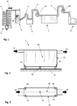
- FIG. 1 shows a schematic illustration of a spinning preparation.
- Fiber flocks 26 are separated from fiber bales 2 by a bale opener 1 and relayed in the conveying direction 12 to a condenser 3.
- the fiber flocks 26 are separated from the transport air in the condenser 3 and temporarily stored.
- the fiber flocks 26 are subsequently conveyed out of the condenser 3 via a transport line 7, and to a mixer 5 via a cleaner 4 and a further transport line 8.
- the conveying of the fiber flocks takes place pneumatically with the aid of a fan 10.
- the fiber flocks are introduced into various chambers, and as a mixture are supplied to a corresponding fan 11 of one or more carding machines 6 via a further transport line 9.
- the fiber flocks are ultimately separated into individual fibers, cleaned, parallelized, and laid down in the form of a sliver, or in the form of a fiber fleece are provided for further processing.
- the illustration of the spinning preparation according to Figure 1 is simplified in order to show one possible sequence of machines, wherein individual machines have a store.
- spinning preparations may have a much more complicated design, and may contain multiple machines, for example further openers or fine cleaners as well as other machines or devices for separating foreign matter.
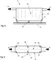
- the installation is provided in such a way that in the empty state of the store 13 of the mixer 5, the load cell 23 is already under a certain load. If the store 13 of the mixer 5 is now filled, the machine frame 16 is slightly bent between the support points 17 and 19 or 18 and 20, as the result of which the load on the load cell 23 increases. This load difference is proportional to the increase in the filling of the store 13 with fiber flocks, on the basis of which the filling level of the mixer 5 may be determined.
- a load cell 23 and 24 are respectively situated on each side of the travel axis 22, between two support points 17 and 19, and 18 and 20, respectively, in such a way that a connecting line 25 through the two load cells 23 and 24 is transverse to the travel axis 22.
- the load cell 23, 24 is installed between the foundation 21 and the machine frame 16. The installation is provided in such a way that in the empty state of the store 13 of the mixer 5, the load cell 23, 24 is already under a certain load. If the store 13 of the mixer 5 is now filled, the machine frame 16 is slightly bent between the support points 17 and 19 or 18 and 20, as the result of which the load on the load cells 23, 24 increases. This load difference is proportional to the increase in the filling of the store 13 with fiber flocks, on the basis of which the filling level of the mixer 5 may be determined.
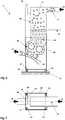
- a discharge element 30 is situated below the store 13.
- the discharge element 30 is made up of multiple pairs of rollers and a conveying air supply line.
- the supplied conveying air 31 accepts the fiber flocks 26 removed from the store 13 by the discharge element 30, and transports them through the fiber flock outlet 15 to a subsequent machine (not shown).
- the condenser 3 and its machine frame 16 are supported in four support points 17 through 20 on a foundation 21.
- the support points 17 through 20 are situated in pairs on both sides of a travel axis 22, which is formed by the connection of the fiber flock inlet 14 to the fiber flock outlet 15.
- a load cell 23, 24 is situated in each case in two of the four support points 17 through 20, as the result of which the machine frame is supported in two support points 17 and 18 on the foundation 21 via the load cells 23 and 24.
Landscapes
- Engineering & Computer Science (AREA)
- Textile Engineering (AREA)
- Preliminary Treatment Of Fibers (AREA)
Abstract
Description
- The invention relates to a machine in a spinning preparation for processing fiber flocks, and a method for measuring a filling level. The machine has a fiber flock inlet, a store, a fiber flock outlet, and a machine frame, the machine frame being mounted on at least four support points on a foundation.
- Fiber processing machines such as cleaners, intermediate stores (so-called condensers), mixers, or carding machines are used in a spinning preparation for cleaning, mixing, and separating the fiber material into individual fibers and parallelizing them.
- In a spinning preparation, the fibers to be prepared for the spinning go through multiple processing steps. For example, in a first step the fibers in the form of fiber flocks are separated from fiber bales. So-called bale openers are usually used for this purpose. These fiber flocks are taken out of the bale opener via a pneumatic flock conveyor and brought to a subsequent cleaning machine. A condenser may be provided as an intermediate store to equalize the flock flow upstream from the cleaner. In this case the pneumatic flock conveyor transports the fiber flocks in a first conveying section from the bale opener to the condenser. In the condenser the fiber flocks are separated from the transport air and supplied to a store. The transport air is discharged as exhaust air via an exhaust air system. From the store, the fiber flocks are supplied to the cleaner with the aid of a fan in a second conveying section. From the cleaner, for example in a further conveying section, the cleaned fiber flocks are pneumatically supplied to a mixer with the aid of a further fan. In the mixer, the fiber flocks are separated from the transport air and stored in various mixing chambers (stores). The stripped transport air is discharged from the mixer. The mixed fiber flocks are transported from the mixer in a further conveying section to an intermediate store with the aid of a fan. The intermediate store is used as an equalizing tank upstream from a further conveying section that supplies the fiber flocks to one or more carding machines. The carding machines, which separate the fiber flocks into individual fibers and form them into a sliver, represent the conclusion of the spinning preparation.
- Various approaches are known from the prior art for filling level measurement in the various types of stores for the spinning preparation machines. According to
DE 1 971 420CH 673 660 A5 DE 10 2013 113 194 A1 proposes to provide within the filling chute (store) a measuring device that detects the change in density of the fiber material as a function of the level of the fiber material. InDE 201 02 245 U1 it is proposed to determine the filling level of filling chutes by means of pressure sensors. For this purpose,CH 662 456 A5 - Accordingly, the object of the invention is to provide a device and a method for measuring a filling level in a store of a machine in the spinning preparation, which allows continuous, interference-free determination of the filling level without being influenced by the design and operation of the filling or emptying of the store, or by the product and its specific properties.
- The object is achieved by the features in the characterizing part of the independent claims.
- To achieve the object, a novel method for measuring the filling level of a store in a spinning preparation and a corresponding machine for a spinning preparation are proposed. The machine for a spinning preparation for processing fiber flocks has a fiber flock inlet, a store, a fiber flock outlet, and a machine frame, the machine frame being mounted on at least four support points on a foundation. A travel axis is defined by a connecting line from the fiber flock inlet to the fiber flock outlet. At least one load cell for measuring a filling level of the store is provided between the machine frame and the foundation. The arrangement of the load cell in one of the support points or between the support points may be selected based on the size and design of the machine. During filling or emptying of the store of the machine, a resulting change in weight is proportional to a load on the machine frame and on the individual support points of the machine.
- However, the load cell is preferably situated in the travel axis. In this way, an asymmetrical load on the load cell may be precluded.
- Various designs of so-called force transducers may be used in load cells. For example, the use of force transducers is known in which the force acts on an elastic spring body and deforms it. The deformation of the spring body is converted to the change in a voltage via strain gauges, whose electrical resistance changes with the strain. The voltage, and thus the change in strain, is recorded via a measuring amplifier. This value may be converted to a measured force value due to the elastic properties of the spring body. Bending bars, ring torsion springs, or other designs are used as a spring body. Piezoceramic elements are used in another design of load cells. The targeted deformation of a piezoelectric material results in the formation of microscopic dipoles within the unit cells of the piezo crystal. Summing over the associated electrical field in all unit cells of the crystal results in a macroscopically measurable voltage that can be converted to a measured force value. Load cells are known from the prior art, and are currently widely used in force and weight measurement.
- The known disadvantages of the filling level measurement in the past are eliminated by use of a load cell. The load cell is not situated in the product stream, thus allowing soiling by the product to be excluded. The filling level measurement by use of a load cell is also independent of the product properties, and the material allocation in the conveying stream likewise has no effect on the filling level measurement. In contrast to a filling level measurement via a pressure sensor inside the store, according to the invention the particular operating pressure that acts on the store does not play a role. The prevailing operating pressure may thus be adapted to the height of the filling level without having to make a corresponding correction of the filling level measurement itself. In addition, operation-related pressure fluctuations in the pneumatic flock conveying system do not affect the filling level measurement.
- Two load cells are advantageously situated between two support points in each case, with a connecting line of the respective two support points being situated transverse to the travel axis. As a result of the arrangement of the load cells between the support points, the load cells are placed under load due to the bending of the machine frame between the support points. However, the primary load on the machine is absorbed in the support points without load cells. In this way it may also be ensured that no transverse forces act on the load cells. In this case, transverse forces that arise are absorbed by the support points without load cells. Arranging the load cells in a line transverse to the travel axis ensures that a one-sided filling level measurement does not take place; instead, the weight of the fiber flocks as a whole in the store is detected. This type of arrangement is suited in particular for machines having a large store, for example mixers, which have a filling capacity of several hundred kilograms. This results in measurable bending of the machine frame between two support points when the machine frame has a suitable design.
- For smaller machines such as intermediate stores or condensers, no measurable bending of the machine frame between the support points is to be expected on account of the smaller filling volume of 50 kg or less. Therefore, as an alternative to the above approach, the at least two load cells are situated in each case in one of the support points, a connecting line of the two support points being situated transverse to the travel axis.
- In another alternative, a load cell is situated in all support points of the machine. Although this design is complicated, it has proven suitable in machines having small stores.
- In addition, it is advantageous when the machine has four support points, and the support points that are not provided with load cells have an articulated design. An articulated design of the support points ensures that even small changes in weight due to the store filling level may be recognized by the load cells during the measurement. This design is advantageous in particular when there is a small distance between the support points. A small distance between the support points results in a rigid structure of the machine frame; with a nonarticulated design of the support points, their rigidity would result in an excessively high level of load transfer with increasing filling of the store.
- The load cells are advantageously connected to a shared evaluation device. The instantaneous filling level is directly output by the evaluation device. The central controller of the machine may also be used as an evaluation device. Corresponding modules that are connected to the load cells are inserted into the central controller; a connection may also be established wirelessly.
- The machine is preferably decoupled from components or piping, connected to the machine, by compensators. The situation may thus be avoided that load changes in the adjoining components or piping are transferred to the filling level measurement, resulting in distortion of the results.
- Vibration dampers are advantageously provided in the support points. Vibration that results from operation of the machine is thus compensated for in the support points, and is not transferred to the overall machine frame and thus, to the filling level measurement.
- In addition, a method for measuring a filling level of a store of a machine in the spinning preparation is proposed, wherein a change in a weight load on the load cells during filling or emptying of the store is measured using at least two load cells between a machine frame and a foundation. It is advantageous when, after a prior calibration with the store empty and/or full, the filling level of the store is calculated from the change in the weight load on the load cells.
- The invention is explained in greater detail below with reference to exemplary embodiments and by use of drawings.
- Figure 1
- shows a schematic illustration of a spinning preparation;
- Figure 2
- shows a schematic illustration of a view of a first embodiment, using a mixer as an example;
- Figure 3
- shows a schematic illustration of a top view of the embodiment according to
Figure 3 ; - Figure 4
- shows a schematic illustration of a view of a second embodiment, using a mixer as an example;
- Figure 5
- shows a schematic illustration of a top view of the embodiment according to
Figure 4 ; - Figure 6
- shows a schematic illustration of a view of a third embodiment, using a condenser as an example; and
- Figure 7
- shows a schematic illustration of a top view of the embodiment according to
Figure 6 . -
Figure 1 shows a schematic illustration of a spinning preparation.Fiber flocks 26 are separated fromfiber bales 2 by abale opener 1 and relayed in the conveyingdirection 12 to acondenser 3. Thefiber flocks 26 are separated from the transport air in thecondenser 3 and temporarily stored. Thefiber flocks 26 are subsequently conveyed out of thecondenser 3 via atransport line 7, and to amixer 5 via acleaner 4 and afurther transport line 8. The conveying of the fiber flocks takes place pneumatically with the aid of afan 10. In the mixer, the fiber flocks are introduced into various chambers, and as a mixture are supplied to a correspondingfan 11 of one ormore carding machines 6 via afurther transport line 9. By means of the carding machines, the fiber flocks are ultimately separated into individual fibers, cleaned, parallelized, and laid down in the form of a sliver, or in the form of a fiber fleece are provided for further processing. The illustration of the spinning preparation according toFigure 1 is simplified in order to show one possible sequence of machines, wherein individual machines have a store. However, spinning preparations may have a much more complicated design, and may contain multiple machines, for example further openers or fine cleaners as well as other machines or devices for separating foreign matter. -
Figure 2 shows a schematic illustration of a view, andFigure 3 shows a top view, of a first embodiment using amixer 5 as an example. Themixer 5 has astore 13 that is situated between afiber flock inlet 14 and afiber flock outlet 15. In addition, themixer 5 has amachine frame 16 that is mounted in foursupport points 17 through 20 on afoundation 21. Thefiber flock inlet 14 and thefiber flock outlet 15 in their connection define atravel axis 22. The support points 17 through 20 are situated in pairs on both sides of thetravel axis 22, at the ends of themixer 5. Aload cell 23 is situated between the support points 17 through 20 in thetravel axis 22. Theload cell 23 is installed between thefoundation 21 and themachine frame 16. The installation is provided in such a way that in the empty state of thestore 13 of themixer 5, theload cell 23 is already under a certain load. If thestore 13 of themixer 5 is now filled, themachine frame 16 is slightly bent between the support points 17 and 19 or 18 and 20, as the result of which the load on theload cell 23 increases. This load difference is proportional to the increase in the filling of thestore 13 with fiber flocks, on the basis of which the filling level of themixer 5 may be determined. -
Figure 4 shows a schematic illustration of a view, andFigure 5 shows a top view, of a first embodiment using amixer 5 as an example. Themixer 5 has astore 13 situated between afiber flock inlet 14 and afiber flock outlet 15. In addition, themixer 5 has amachine frame 16 that is mounted in foursupport points 17 through 20 on afoundation 21. Thefiber flock inlet 14 and thefiber flock outlet 15 in their connection define atravel axis 22. The support points 17 through 20 are situated in pairs on both sides of thetravel axis 22, at the ends of themixer 5. Aload cell travel axis 22, between twosupport points line 25 through the twoload cells travel axis 22. Theload cell foundation 21 and themachine frame 16. The installation is provided in such a way that in the empty state of thestore 13 of themixer 5, theload cell store 13 of themixer 5 is now filled, themachine frame 16 is slightly bent between the support points 17 and 19 or 18 and 20, as the result of which the load on theload cells store 13 with fiber flocks, on the basis of which the filling level of themixer 5 may be determined. -
Figure 6 shows a schematic illustration of a view, andFigure 7 shows a top view, of a second embodiment using acondenser 3 as an example. Thecondenser 3 is made up essentially of amachine frame 16 and astore 13 held in themachine frame 16. Thefiber flocks 26 in a fiber flock-conveyingair mixture 27 are introduced into thestore 13 via afiber flock inlet 14. Thestore 13 has an air-permeable partition 28 by means of which the conveying air is separated from thefiber flocks 26. As a result, the conveying air is discharged from thecondenser 3 asexhaust air 29. As thefilling level 32 rises, the air-permeable wall 28 becomes increasingly covered, resulting in a greater resistance for the conveyingair 29, and thus, a pressure rise in thestore 13. This circumstance has been utilized in the past to determine thefilling level 32 by means of a pressure measurement. - A
discharge element 30 is situated below thestore 13. Thedischarge element 30 is made up of multiple pairs of rollers and a conveying air supply line. The supplied conveyingair 31 accepts thefiber flocks 26 removed from thestore 13 by thedischarge element 30, and transports them through thefiber flock outlet 15 to a subsequent machine (not shown). Thecondenser 3 and itsmachine frame 16 are supported in foursupport points 17 through 20 on afoundation 21. The support points 17 through 20 are situated in pairs on both sides of atravel axis 22, which is formed by the connection of thefiber flock inlet 14 to thefiber flock outlet 15. Aload cell support points 17 through 20, as the result of which the machine frame is supported in twosupport points foundation 21 via theload cells line 25 of the twoload cells travel axis 22. When the height of thefilling level 32 increases, the weight of theoverall condenser 3 also increases. This change in weight may be directly measured by theload cells instantaneous filling level 32 may thus be determined at any time based on the weight measurement. - The present invention is not limited to the exemplary embodiments illustrated and described. Within the scope of the patent claims, modifications are possible as well as a combination of the features, even when they are illustrated and described in different exemplary embodiments.
-
- 1
- bale opener
- 2
- fiber bales
- 3
- condenser
- 4
- cleaner
- 5
- mixer
- 6
- carding machine
- 7, 8, 9
- conveying line
- 10,11
- fan
- 12
- conveying direction
- 13
- store
- 14
- fiber flock inlet
- 15
- fiber flock outlet
- 16
- machine frame
- 17-20
- support point
- 21
- foundation
- 22
- travel axis
- 23, 24
- load cell
- 25
- connecting line
- 26
- fiber flocks
- 27
- mixture of fiber flocks and conveying air
- 28
- air-permeable partition
- 29
- exhaust air
- 30
- discharge element
- 31
- conveying air
- 32
- filling level
Claims (11)
- A machine (3, 5) in a spinning preparation for processing fiber flocks (26), having a fiber flock inlet (14), a store (13), a fiber flock outlet (15), and a machine frame (16), wherein the machine frame (16) is mounted on at least four support points (17, 18, 19, 20) on a foundation (21), and a travel axis (22) is defined by a connecting line from the fiber flock inlet (14) to the fiber flock outlet (15), characterized in that at least one load cell (23) for measuring a filling level (32) of the store (13) is provided between the machine frame (16) and the foundation (21).
- The machine (3, 5) according to Claim 1, characterized in that the load cell (23) is situated in the travel axis (22).
- The machine (3, 5) according to Claim 1, characterized in that two load cells (23, 24) are situated between two support points (17, 18, 19, 20) in each case, a connecting line (25) of the two load cells (23, 24) being situated transverse to the travel axis (22).
- The machine (3, 5) according to Claim 1, characterized in that at least two load cells (23, 24) are situated in each case in one of the support points (17, 18, 19, 20), a connecting line (25) of the two load cells (23, 24) being situated transverse to the travel axis (22).
- The machine (3, 5) according to Claim 1, characterized in that a load cell (23, 24) is situated in all support points (17, 18, 19, 20) of the machine (3, 5).
- The machine (3, 5) according to one of Claims 1 to 4, characterized in that the machine (3, 5) has four support points (17, 18, 19, 20), and the support points (17, 18, 19, 20) that are not provided with load cells (23, 24) have an articulated design.
- The machine (3, 5) according to one of Claims 3 to 6, characterized in that the load cells (23, 24) are connected to a shared evaluation device.
- The machine (3, 5) according to one of the preceding claims, characterized in that the machine (3, 5) is decoupled from components or piping, connected to the machine (3, 5), by compensators.
- The machine (3, 5) according to one of the preceding claims, characterized in that vibration dampers are provided in the support points (17, 18, 19, 20).
- A method for measuring a filling level (32) of a store (13) of a machine (3, 5) in a spinning preparation, characterized in that a change in a weight load on the load cell (23) during filling or emptying of the store (13) is measured using at least one load cell (23) between a machine frame (16) and a foundation (21).
- The method according to Claim 10, characterized in that after a prior calibration with the store (13) empty and/or full, the filling level (32) of the store (13) is calculated from the change in the weight load on the at least one load cell (23).
Applications Claiming Priority (1)
| Application Number | Priority Date | Filing Date | Title |
|---|---|---|---|
| CH00735/18A CH715076A1 (en) | 2018-06-07 | 2018-06-07 | Level measurement of a fiber flake storage. |
Publications (2)
| Publication Number | Publication Date |
|---|---|
| EP3587631A1 true EP3587631A1 (en) | 2020-01-01 |
| EP3587631B1 EP3587631B1 (en) | 2024-01-03 |
Family
ID=66630188
Family Applications (1)
| Application Number | Title | Priority Date | Filing Date |
|---|---|---|---|
| EP19175839.0A Active EP3587631B1 (en) | 2018-06-07 | 2019-05-22 | Filling level measurement of a fiber flock store |
Country Status (3)
| Country | Link |
|---|---|
| EP (1) | EP3587631B1 (en) |
| CN (1) | CN110578191A (en) |
| CH (1) | CH715076A1 (en) |
Cited By (3)
| Publication number | Priority date | Publication date | Assignee | Title |
|---|---|---|---|---|
| WO2021149073A1 (en) * | 2020-01-22 | 2021-07-29 | Jothimurugan Amirthalingam | Weight measuring apparatus for spinning containers and a method therefor |
| GB2594681A (en) * | 2020-02-07 | 2021-11-10 | Lightowlers Yarns Ltd | Improvements in and relating to manufacture of yarn and fabric |
| WO2023174885A1 (en) | 2022-03-18 | 2023-09-21 | Trützschler Group SE | Spinning preparation machine for processing fibre flocks |
Citations (10)
| Publication number | Priority date | Publication date | Assignee | Title |
|---|---|---|---|---|
| DE1971420U (en) | 1966-09-03 | 1967-10-26 | Truetzschler & Co | DEVICE FOR CONVEYING FIBERS OD. DGL. BY AIR PRESSURE. |
| CH662456A5 (en) | 1982-02-12 | 1987-09-30 | Truetzschler & Co | ELECTRONIC PRESSURE SWITCH, ESPECIALLY AS A MEASURING PART FOR DETECTING PRESSURE VARIATIONS IN TEXTILE MACHINES. |
| US4723344A (en) * | 1985-04-13 | 1988-02-09 | Trutzschler Gmbh & Co. Kg | Method and apparatus for opening fiber bales |
| US4823440A (en) * | 1986-07-18 | 1989-04-25 | John D. Hollingsworth On Wheels, Inc. | Web weight control system |
| CH673660A5 (en) | 1986-06-23 | 1990-03-30 | Truetzschler & Co | |
| DE20102245U1 (en) | 2001-02-09 | 2001-04-12 | Maschinenfabrik Rieter Ag, Winterthur | Device for the pneumatic feeding of fiber flakes to the filling shafts of cards placed in a carding line |
| US20040255429A1 (en) * | 2003-05-13 | 2004-12-23 | Peter Clausen | Fiber dispensing apparatus |
| DE102013113194A1 (en) | 2013-02-06 | 2014-08-07 | TRüTZSCHLER GMBH & CO. KG | Apparatus for controlling material flows in plants for processing of e.g. natural fibers, has measurement device comprising measuring points and controller and utilizing measurement signal of measuring point to control mass flow of material |
| US20150308884A1 (en) * | 2012-11-27 | 2015-10-29 | Yamato Scale Co., Ltd | Packer Scale |
| DE202014010744U1 (en) * | 2014-08-07 | 2016-06-29 | Trützschler GmbH & Co Kommanditgesellschaft | Device for mixing fiber components |
Family Cites Families (10)
| Publication number | Priority date | Publication date | Assignee | Title |
|---|---|---|---|---|
| GB1558101A (en) * | 1976-04-26 | 1979-12-19 | Vibro Dynamics Corp | Load sensing support system |
| DE3534933A1 (en) * | 1985-10-01 | 1987-04-09 | Truetzschler & Co | DEVICE FOR MEASURING THE QUANTITY OF FIBERS TO BE SUPPLIED TO A TEXTILE MACHINE |
| DE3905139A1 (en) * | 1989-02-20 | 1990-08-23 | Truetzschler & Co | METHOD AND DEVICE FOR MEASURING, REGULATING AND CONTROLLING THE AMOUNT OF A FLOW OF FIBER FLAKES IN FLIGHT |
| DE4200240C2 (en) * | 1992-01-08 | 1993-11-25 | Leopold Jungbauer | Weighing and filling device for fluffy material that can be transported by air |
| US5575040A (en) * | 1993-05-14 | 1996-11-19 | Trutzschler Gmbh & Co. Kg | Apparatus for controlling sliver deposition in a coiler can |
| NL1013821C1 (en) * | 1999-12-10 | 2001-06-12 | Meneba Meel B V | Device and method for the supply in bulk of ground or granular products to small consumers. |
| CH706658A1 (en) * | 2012-06-29 | 2013-12-31 | Rieter Ag Maschf | Method and apparatus for controlling the supply of fiber to a carding machine. |
| US9266662B1 (en) * | 2012-09-11 | 2016-02-23 | Vm Fiber Feeders Inc. | Bulk fiber dispenser |
| DE102015106415A1 (en) * | 2014-12-13 | 2016-06-16 | Trützschler GmbH + Co KG Textilmaschinenfabrik | Method and device for feeding a system with fibers |
| CN205839221U (en) * | 2016-07-25 | 2016-12-28 | 青岛曹大海机械有限公司 | A kind of full-automatic opener fills cotton production line |
-
2018
- 2018-06-07 CH CH00735/18A patent/CH715076A1/en not_active Application Discontinuation
-
2019
- 2019-05-22 EP EP19175839.0A patent/EP3587631B1/en active Active
- 2019-06-05 CN CN201910487147.0A patent/CN110578191A/en active Pending
Patent Citations (10)
| Publication number | Priority date | Publication date | Assignee | Title |
|---|---|---|---|---|
| DE1971420U (en) | 1966-09-03 | 1967-10-26 | Truetzschler & Co | DEVICE FOR CONVEYING FIBERS OD. DGL. BY AIR PRESSURE. |
| CH662456A5 (en) | 1982-02-12 | 1987-09-30 | Truetzschler & Co | ELECTRONIC PRESSURE SWITCH, ESPECIALLY AS A MEASURING PART FOR DETECTING PRESSURE VARIATIONS IN TEXTILE MACHINES. |
| US4723344A (en) * | 1985-04-13 | 1988-02-09 | Trutzschler Gmbh & Co. Kg | Method and apparatus for opening fiber bales |
| CH673660A5 (en) | 1986-06-23 | 1990-03-30 | Truetzschler & Co | |
| US4823440A (en) * | 1986-07-18 | 1989-04-25 | John D. Hollingsworth On Wheels, Inc. | Web weight control system |
| DE20102245U1 (en) | 2001-02-09 | 2001-04-12 | Maschinenfabrik Rieter Ag, Winterthur | Device for the pneumatic feeding of fiber flakes to the filling shafts of cards placed in a carding line |
| US20040255429A1 (en) * | 2003-05-13 | 2004-12-23 | Peter Clausen | Fiber dispensing apparatus |
| US20150308884A1 (en) * | 2012-11-27 | 2015-10-29 | Yamato Scale Co., Ltd | Packer Scale |
| DE102013113194A1 (en) | 2013-02-06 | 2014-08-07 | TRüTZSCHLER GMBH & CO. KG | Apparatus for controlling material flows in plants for processing of e.g. natural fibers, has measurement device comprising measuring points and controller and utilizing measurement signal of measuring point to control mass flow of material |
| DE202014010744U1 (en) * | 2014-08-07 | 2016-06-29 | Trützschler GmbH & Co Kommanditgesellschaft | Device for mixing fiber components |
Cited By (9)
| Publication number | Priority date | Publication date | Assignee | Title |
|---|---|---|---|---|
| WO2021149073A1 (en) * | 2020-01-22 | 2021-07-29 | Jothimurugan Amirthalingam | Weight measuring apparatus for spinning containers and a method therefor |
| GB2594681A (en) * | 2020-02-07 | 2021-11-10 | Lightowlers Yarns Ltd | Improvements in and relating to manufacture of yarn and fabric |
| GB2594681B (en) * | 2020-02-07 | 2022-09-21 | Moorbrook Textiles Ltd | Improvements in and relating to manufacture of yarn and fabric |
| WO2023174885A1 (en) | 2022-03-18 | 2023-09-21 | Trützschler Group SE | Spinning preparation machine for processing fibre flocks |
| WO2023174886A1 (en) | 2022-03-18 | 2023-09-21 | Trützschler Group SE | Method for gravimetrically measuring the fill level of a spinning preparation machine, and spinning preparation machine |
| CN118140018A (en) * | 2022-03-18 | 2024-06-04 | 特吕茨施勒集团欧洲公司 | Spinning preparation machines for processing fiber bundles |
| CN118284726A (en) * | 2022-03-18 | 2024-07-02 | 特吕茨施勒集团欧洲公司 | Method for gravimetric measurement of the filling state of a spinning preparation machine and spinning preparation machine |
| EP4671420A2 (en) | 2022-03-18 | 2025-12-31 | Trützschler Group SE | METHOD FOR GRAVIMETRICAL LEVEL MEASUREMENT OF A SPINNING RICE PREPARATION MACHINE AND SPINNING RICE PREPARATION MACHINE |
| EP4671420A3 (en) * | 2022-03-18 | 2026-03-11 | Trützschler Group SE | Method for gravimetric fill level measurement of a spinning preparation machine and spinning preparation machine |
Also Published As
| Publication number | Publication date |
|---|---|
| EP3587631B1 (en) | 2024-01-03 |
| CH715076A1 (en) | 2019-12-13 |
| CN110578191A (en) | 2019-12-17 |
Similar Documents
| Publication | Publication Date | Title |
|---|---|---|
| EP3587631A1 (en) | Filling level measurement of a fiber flock store | |
| US9637320B2 (en) | Pneumatic transport system of granular material and control method of such system | |
| JP4880321B2 (en) | Combination weigher and weighing device using the same | |
| US4901807A (en) | Combination weigher with multiple compartment weighing receptacles | |
| CN102616393B (en) | Medicine weighing and loading machine and use method thereof | |
| CA2646431C (en) | Combination weigher | |
| AU2016216986B2 (en) | Conveyor apparatus and combined weighing apparatus | |
| CN102209475A (en) | Device and method for feeding cut tobacco from a tobacco delivery unit to a tobacco processing machine | |
| US6186194B1 (en) | Process and device for bagging a certain number of grains in each sack | |
| US7566837B2 (en) | Combination weigher | |
| CN107209048B (en) | Combined metering device | |
| US4744453A (en) | Apparatus for temporary storage of cigarettes or the like | |
| US5455395A (en) | Pipe chain conveyor | |
| CN108268930B (en) | Bar weighing counter and weighing counting method | |
| US5121522A (en) | Humidity and temperature air conditioning in a textile processing line | |
| GB2183349A (en) | Measuring fibre supplied to a textile machine | |
| CN114223936A (en) | Material flexible metering unit and multi-bin single-tube metering flexible feeding system and method | |
| CN110088580B (en) | Combined metering device | |
| CN206556758U (en) | The online scale correcting apparatus of belted electronic balance | |
| CN210047681U (en) | Combined weighing device | |
| EP3633086B1 (en) | Flock conveyance in a fiber preparation system | |
| CN104760918B (en) | Weighing box of woolen filling machine with buffer function and wooden filling method thereof | |
| CN218756225U (en) | Mixed ring type crossed blending system | |
| CN205470030U (en) | Accurate count system of irregular lump material | |
| CN101619511A (en) | Feeding device |
Legal Events
| Date | Code | Title | Description |
|---|---|---|---|
| PUAI | Public reference made under article 153(3) epc to a published international application that has entered the european phase |
Free format text: ORIGINAL CODE: 0009012 |
|
| STAA | Information on the status of an ep patent application or granted ep patent |
Free format text: STATUS: THE APPLICATION HAS BEEN PUBLISHED |
|
| AK | Designated contracting states |
Kind code of ref document: A1 Designated state(s): AL AT BE BG CH CY CZ DE DK EE ES FI FR GB GR HR HU IE IS IT LI LT LU LV MC MK MT NL NO PL PT RO RS SE SI SK SM TR |
|
| AX | Request for extension of the european patent |
Extension state: BA ME |
|
| STAA | Information on the status of an ep patent application or granted ep patent |
Free format text: STATUS: REQUEST FOR EXAMINATION WAS MADE |
|
| 17P | Request for examination filed |
Effective date: 20200612 |
|
| RBV | Designated contracting states (corrected) |
Designated state(s): AL AT BE BG CH CY CZ DE DK EE ES FI FR GB GR HR HU IE IS IT LI LT LU LV MC MK MT NL NO PL PT RO RS SE SI SK SM TR |
|
| STAA | Information on the status of an ep patent application or granted ep patent |
Free format text: STATUS: EXAMINATION IS IN PROGRESS |
|
| 17Q | First examination report despatched |
Effective date: 20211029 |
|
| P01 | Opt-out of the competence of the unified patent court (upc) registered |
Effective date: 20230519 |
|
| RIC1 | Information provided on ipc code assigned before grant |
Ipc: D01G 31/00 20060101ALI20230623BHEP Ipc: D01G 23/04 20060101AFI20230623BHEP |
|
| GRAP | Despatch of communication of intention to grant a patent |
Free format text: ORIGINAL CODE: EPIDOSNIGR1 |
|
| STAA | Information on the status of an ep patent application or granted ep patent |
Free format text: STATUS: GRANT OF PATENT IS INTENDED |
|
| INTG | Intention to grant announced |
Effective date: 20230816 |
|
| GRAS | Grant fee paid |
Free format text: ORIGINAL CODE: EPIDOSNIGR3 |
|
| GRAA | (expected) grant |
Free format text: ORIGINAL CODE: 0009210 |
|
| STAA | Information on the status of an ep patent application or granted ep patent |
Free format text: STATUS: THE PATENT HAS BEEN GRANTED |
|
| AK | Designated contracting states |
Kind code of ref document: B1 Designated state(s): AL AT BE BG CH CY CZ DE DK EE ES FI FR GB GR HR HU IE IS IT LI LT LU LV MC MK MT NL NO PL PT RO RS SE SI SK SM TR |
|
| REG | Reference to a national code |
Ref country code: GB Ref legal event code: FG4D |
|
| REG | Reference to a national code |
Ref country code: DE Ref legal event code: R096 Ref document number: 602019044313 Country of ref document: DE |
|
| REG | Reference to a national code |
Ref country code: CH Ref legal event code: EP |
|
| REG | Reference to a national code |
Ref country code: IE Ref legal event code: FG4D |
|
| REG | Reference to a national code |
Ref country code: LT Ref legal event code: MG9D |
|
| PG25 | Lapsed in a contracting state [announced via postgrant information from national office to epo] |
Ref country code: ES Free format text: LAPSE BECAUSE OF FAILURE TO SUBMIT A TRANSLATION OF THE DESCRIPTION OR TO PAY THE FEE WITHIN THE PRESCRIBED TIME-LIMIT Effective date: 20240103 |
|
| PG25 | Lapsed in a contracting state [announced via postgrant information from national office to epo] |
Ref country code: ES Free format text: LAPSE BECAUSE OF FAILURE TO SUBMIT A TRANSLATION OF THE DESCRIPTION OR TO PAY THE FEE WITHIN THE PRESCRIBED TIME-LIMIT Effective date: 20240103 |
|
| REG | Reference to a national code |
Ref country code: NL Ref legal event code: MP Effective date: 20240103 |
|
| REG | Reference to a national code |
Ref country code: AT Ref legal event code: MK05 Ref document number: 1646859 Country of ref document: AT Kind code of ref document: T Effective date: 20240103 |
|
| PG25 | Lapsed in a contracting state [announced via postgrant information from national office to epo] |
Ref country code: NL Free format text: LAPSE BECAUSE OF FAILURE TO SUBMIT A TRANSLATION OF THE DESCRIPTION OR TO PAY THE FEE WITHIN THE PRESCRIBED TIME-LIMIT Effective date: 20240103 |
|
| PG25 | Lapsed in a contracting state [announced via postgrant information from national office to epo] |
Ref country code: NL Free format text: LAPSE BECAUSE OF FAILURE TO SUBMIT A TRANSLATION OF THE DESCRIPTION OR TO PAY THE FEE WITHIN THE PRESCRIBED TIME-LIMIT Effective date: 20240103 |
|
| PG25 | Lapsed in a contracting state [announced via postgrant information from national office to epo] |
Ref country code: IS Free format text: LAPSE BECAUSE OF FAILURE TO SUBMIT A TRANSLATION OF THE DESCRIPTION OR TO PAY THE FEE WITHIN THE PRESCRIBED TIME-LIMIT Effective date: 20240503 |
|
| PG25 | Lapsed in a contracting state [announced via postgrant information from national office to epo] |
Ref country code: LT Free format text: LAPSE BECAUSE OF FAILURE TO SUBMIT A TRANSLATION OF THE DESCRIPTION OR TO PAY THE FEE WITHIN THE PRESCRIBED TIME-LIMIT Effective date: 20240103 |
|
| PG25 | Lapsed in a contracting state [announced via postgrant information from national office to epo] |
Ref country code: GR Free format text: LAPSE BECAUSE OF FAILURE TO SUBMIT A TRANSLATION OF THE DESCRIPTION OR TO PAY THE FEE WITHIN THE PRESCRIBED TIME-LIMIT Effective date: 20240404 |
|
| PG25 | Lapsed in a contracting state [announced via postgrant information from national office to epo] |
Ref country code: HR Free format text: LAPSE BECAUSE OF FAILURE TO SUBMIT A TRANSLATION OF THE DESCRIPTION OR TO PAY THE FEE WITHIN THE PRESCRIBED TIME-LIMIT Effective date: 20240103 Ref country code: RS Free format text: LAPSE BECAUSE OF FAILURE TO SUBMIT A TRANSLATION OF THE DESCRIPTION OR TO PAY THE FEE WITHIN THE PRESCRIBED TIME-LIMIT Effective date: 20240403 |
|
| PG25 | Lapsed in a contracting state [announced via postgrant information from national office to epo] |
Ref country code: AT Free format text: LAPSE BECAUSE OF FAILURE TO SUBMIT A TRANSLATION OF THE DESCRIPTION OR TO PAY THE FEE WITHIN THE PRESCRIBED TIME-LIMIT Effective date: 20240103 Ref country code: CZ Free format text: LAPSE BECAUSE OF FAILURE TO SUBMIT A TRANSLATION OF THE DESCRIPTION OR TO PAY THE FEE WITHIN THE PRESCRIBED TIME-LIMIT Effective date: 20240103 |
|
| PG25 | Lapsed in a contracting state [announced via postgrant information from national office to epo] |
Ref country code: RS Free format text: LAPSE BECAUSE OF FAILURE TO SUBMIT A TRANSLATION OF THE DESCRIPTION OR TO PAY THE FEE WITHIN THE PRESCRIBED TIME-LIMIT Effective date: 20240403 Ref country code: NO Free format text: LAPSE BECAUSE OF FAILURE TO SUBMIT A TRANSLATION OF THE DESCRIPTION OR TO PAY THE FEE WITHIN THE PRESCRIBED TIME-LIMIT Effective date: 20240403 Ref country code: LT Free format text: LAPSE BECAUSE OF FAILURE TO SUBMIT A TRANSLATION OF THE DESCRIPTION OR TO PAY THE FEE WITHIN THE PRESCRIBED TIME-LIMIT Effective date: 20240103 Ref country code: IS Free format text: LAPSE BECAUSE OF FAILURE TO SUBMIT A TRANSLATION OF THE DESCRIPTION OR TO PAY THE FEE WITHIN THE PRESCRIBED TIME-LIMIT Effective date: 20240503 Ref country code: HR Free format text: LAPSE BECAUSE OF FAILURE TO SUBMIT A TRANSLATION OF THE DESCRIPTION OR TO PAY THE FEE WITHIN THE PRESCRIBED TIME-LIMIT Effective date: 20240103 Ref country code: GR Free format text: LAPSE BECAUSE OF FAILURE TO SUBMIT A TRANSLATION OF THE DESCRIPTION OR TO PAY THE FEE WITHIN THE PRESCRIBED TIME-LIMIT Effective date: 20240404 Ref country code: CZ Free format text: LAPSE BECAUSE OF FAILURE TO SUBMIT A TRANSLATION OF THE DESCRIPTION OR TO PAY THE FEE WITHIN THE PRESCRIBED TIME-LIMIT Effective date: 20240103 Ref country code: BG Free format text: LAPSE BECAUSE OF FAILURE TO SUBMIT A TRANSLATION OF THE DESCRIPTION OR TO PAY THE FEE WITHIN THE PRESCRIBED TIME-LIMIT Effective date: 20240103 Ref country code: AT Free format text: LAPSE BECAUSE OF FAILURE TO SUBMIT A TRANSLATION OF THE DESCRIPTION OR TO PAY THE FEE WITHIN THE PRESCRIBED TIME-LIMIT Effective date: 20240103 |
|
| PG25 | Lapsed in a contracting state [announced via postgrant information from national office to epo] |
Ref country code: PL Free format text: LAPSE BECAUSE OF FAILURE TO SUBMIT A TRANSLATION OF THE DESCRIPTION OR TO PAY THE FEE WITHIN THE PRESCRIBED TIME-LIMIT Effective date: 20240103 Ref country code: PT Free format text: LAPSE BECAUSE OF FAILURE TO SUBMIT A TRANSLATION OF THE DESCRIPTION OR TO PAY THE FEE WITHIN THE PRESCRIBED TIME-LIMIT Effective date: 20240503 |
|
| RAP4 | Party data changed (patent owner data changed or rights of a patent transferred) |
Owner name: RIETER AG |
|
| PG25 | Lapsed in a contracting state [announced via postgrant information from national office to epo] |
Ref country code: SE Free format text: LAPSE BECAUSE OF FAILURE TO SUBMIT A TRANSLATION OF THE DESCRIPTION OR TO PAY THE FEE WITHIN THE PRESCRIBED TIME-LIMIT Effective date: 20240103 Ref country code: PT Free format text: LAPSE BECAUSE OF FAILURE TO SUBMIT A TRANSLATION OF THE DESCRIPTION OR TO PAY THE FEE WITHIN THE PRESCRIBED TIME-LIMIT Effective date: 20240503 Ref country code: PL Free format text: LAPSE BECAUSE OF FAILURE TO SUBMIT A TRANSLATION OF THE DESCRIPTION OR TO PAY THE FEE WITHIN THE PRESCRIBED TIME-LIMIT Effective date: 20240103 Ref country code: LV Free format text: LAPSE BECAUSE OF FAILURE TO SUBMIT A TRANSLATION OF THE DESCRIPTION OR TO PAY THE FEE WITHIN THE PRESCRIBED TIME-LIMIT Effective date: 20240103 |
|
| REG | Reference to a national code |
Ref country code: DE Ref legal event code: R097 Ref document number: 602019044313 Country of ref document: DE |
|
| PG25 | Lapsed in a contracting state [announced via postgrant information from national office to epo] |
Ref country code: DK Free format text: LAPSE BECAUSE OF FAILURE TO SUBMIT A TRANSLATION OF THE DESCRIPTION OR TO PAY THE FEE WITHIN THE PRESCRIBED TIME-LIMIT Effective date: 20240103 |
|
| PG25 | Lapsed in a contracting state [announced via postgrant information from national office to epo] |
Ref country code: SM Free format text: LAPSE BECAUSE OF FAILURE TO SUBMIT A TRANSLATION OF THE DESCRIPTION OR TO PAY THE FEE WITHIN THE PRESCRIBED TIME-LIMIT Effective date: 20240103 |
|
| PG25 | Lapsed in a contracting state [announced via postgrant information from national office to epo] |
Ref country code: EE Free format text: LAPSE BECAUSE OF FAILURE TO SUBMIT A TRANSLATION OF THE DESCRIPTION OR TO PAY THE FEE WITHIN THE PRESCRIBED TIME-LIMIT Effective date: 20240103 |
|
| PG25 | Lapsed in a contracting state [announced via postgrant information from national office to epo] |
Ref country code: SK Free format text: LAPSE BECAUSE OF FAILURE TO SUBMIT A TRANSLATION OF THE DESCRIPTION OR TO PAY THE FEE WITHIN THE PRESCRIBED TIME-LIMIT Effective date: 20240103 |
|
| PG25 | Lapsed in a contracting state [announced via postgrant information from national office to epo] |
Ref country code: SM Free format text: LAPSE BECAUSE OF FAILURE TO SUBMIT A TRANSLATION OF THE DESCRIPTION OR TO PAY THE FEE WITHIN THE PRESCRIBED TIME-LIMIT Effective date: 20240103 Ref country code: SK Free format text: LAPSE BECAUSE OF FAILURE TO SUBMIT A TRANSLATION OF THE DESCRIPTION OR TO PAY THE FEE WITHIN THE PRESCRIBED TIME-LIMIT Effective date: 20240103 Ref country code: RO Free format text: LAPSE BECAUSE OF FAILURE TO SUBMIT A TRANSLATION OF THE DESCRIPTION OR TO PAY THE FEE WITHIN THE PRESCRIBED TIME-LIMIT Effective date: 20240103 Ref country code: EE Free format text: LAPSE BECAUSE OF FAILURE TO SUBMIT A TRANSLATION OF THE DESCRIPTION OR TO PAY THE FEE WITHIN THE PRESCRIBED TIME-LIMIT Effective date: 20240103 Ref country code: DK Free format text: LAPSE BECAUSE OF FAILURE TO SUBMIT A TRANSLATION OF THE DESCRIPTION OR TO PAY THE FEE WITHIN THE PRESCRIBED TIME-LIMIT Effective date: 20240103 |
|
| PLBE | No opposition filed within time limit |
Free format text: ORIGINAL CODE: 0009261 |
|
| STAA | Information on the status of an ep patent application or granted ep patent |
Free format text: STATUS: NO OPPOSITION FILED WITHIN TIME LIMIT |
|
| PG25 | Lapsed in a contracting state [announced via postgrant information from national office to epo] |
Ref country code: IT Free format text: LAPSE BECAUSE OF FAILURE TO SUBMIT A TRANSLATION OF THE DESCRIPTION OR TO PAY THE FEE WITHIN THE PRESCRIBED TIME-LIMIT Effective date: 20240103 |
|
| 26N | No opposition filed |
Effective date: 20241007 |
|
| REG | Reference to a national code |
Ref country code: CH Ref legal event code: PL |
|
| PG25 | Lapsed in a contracting state [announced via postgrant information from national office to epo] |
Ref country code: IT Free format text: LAPSE BECAUSE OF FAILURE TO SUBMIT A TRANSLATION OF THE DESCRIPTION OR TO PAY THE FEE WITHIN THE PRESCRIBED TIME-LIMIT Effective date: 20240103 |
|
| PG25 | Lapsed in a contracting state [announced via postgrant information from national office to epo] |
Ref country code: MC Free format text: LAPSE BECAUSE OF FAILURE TO SUBMIT A TRANSLATION OF THE DESCRIPTION OR TO PAY THE FEE WITHIN THE PRESCRIBED TIME-LIMIT Effective date: 20240103 |
|
| PG25 | Lapsed in a contracting state [announced via postgrant information from national office to epo] |
Ref country code: LU Free format text: LAPSE BECAUSE OF NON-PAYMENT OF DUE FEES Effective date: 20240522 |
|
| GBPC | Gb: european patent ceased through non-payment of renewal fee |
Effective date: 20240522 |
|
| PG25 | Lapsed in a contracting state [announced via postgrant information from national office to epo] |
Ref country code: MC Free format text: LAPSE BECAUSE OF FAILURE TO SUBMIT A TRANSLATION OF THE DESCRIPTION OR TO PAY THE FEE WITHIN THE PRESCRIBED TIME-LIMIT Effective date: 20240103 Ref country code: LU Free format text: LAPSE BECAUSE OF NON-PAYMENT OF DUE FEES Effective date: 20240522 Ref country code: CH Free format text: LAPSE BECAUSE OF NON-PAYMENT OF DUE FEES Effective date: 20240531 |
|
| REG | Reference to a national code |
Ref country code: BE Ref legal event code: MM Effective date: 20240531 |
|
| PG25 | Lapsed in a contracting state [announced via postgrant information from national office to epo] |
Ref country code: IE Free format text: LAPSE BECAUSE OF NON-PAYMENT OF DUE FEES Effective date: 20240522 |
|
| PG25 | Lapsed in a contracting state [announced via postgrant information from national office to epo] |
Ref country code: SI Free format text: LAPSE BECAUSE OF FAILURE TO SUBMIT A TRANSLATION OF THE DESCRIPTION OR TO PAY THE FEE WITHIN THE PRESCRIBED TIME-LIMIT Effective date: 20240103 Ref country code: BE Free format text: LAPSE BECAUSE OF NON-PAYMENT OF DUE FEES Effective date: 20240531 |
|
| PG25 | Lapsed in a contracting state [announced via postgrant information from national office to epo] |
Ref country code: FR Free format text: LAPSE BECAUSE OF NON-PAYMENT OF DUE FEES Effective date: 20240531 |
|
| PG25 | Lapsed in a contracting state [announced via postgrant information from national office to epo] |
Ref country code: GB Free format text: LAPSE BECAUSE OF NON-PAYMENT OF DUE FEES Effective date: 20240522 |
|
| PGFP | Annual fee paid to national office [announced via postgrant information from national office to epo] |
Ref country code: DE Payment date: 20250519 Year of fee payment: 7 |
|
| PGFP | Annual fee paid to national office [announced via postgrant information from national office to epo] |
Ref country code: TR Payment date: 20250515 Year of fee payment: 7 |
|
| PG25 | Lapsed in a contracting state [announced via postgrant information from national office to epo] |
Ref country code: CY Free format text: LAPSE BECAUSE OF FAILURE TO SUBMIT A TRANSLATION OF THE DESCRIPTION OR TO PAY THE FEE WITHIN THE PRESCRIBED TIME-LIMIT; INVALID AB INITIO Effective date: 20190522 |
|
| PG25 | Lapsed in a contracting state [announced via postgrant information from national office to epo] |
Ref country code: HU Free format text: LAPSE BECAUSE OF FAILURE TO SUBMIT A TRANSLATION OF THE DESCRIPTION OR TO PAY THE FEE WITHIN THE PRESCRIBED TIME-LIMIT; INVALID AB INITIO Effective date: 20190522 |
|
| PG25 | Lapsed in a contracting state [announced via postgrant information from national office to epo] |
Ref country code: FI Free format text: LAPSE BECAUSE OF FAILURE TO SUBMIT A TRANSLATION OF THE DESCRIPTION OR TO PAY THE FEE WITHIN THE PRESCRIBED TIME-LIMIT Effective date: 20240103 |