EP3587620A1 - Device for pulsed laser deposition and a substrate with a substrate surface for reduction of particles on the substrate - Google Patents
Device for pulsed laser deposition and a substrate with a substrate surface for reduction of particles on the substrate Download PDFInfo
- Publication number
- EP3587620A1 EP3587620A1 EP18180369.3A EP18180369A EP3587620A1 EP 3587620 A1 EP3587620 A1 EP 3587620A1 EP 18180369 A EP18180369 A EP 18180369A EP 3587620 A1 EP3587620 A1 EP 3587620A1
- Authority
- EP
- European Patent Office
- Prior art keywords
- plasma
- substrate
- target
- passage opening
- hole plate
- Prior art date
- Legal status (The legal status is an assumption and is not a legal conclusion. Google has not performed a legal analysis and makes no representation as to the accuracy of the status listed.)
- Pending
Links
- 239000000758 substrate Substances 0.000 title claims abstract description 64
- 238000004549 pulsed laser deposition Methods 0.000 title claims abstract description 8
- 239000002245 particle Substances 0.000 title description 46
- 238000011144 upstream manufacturing Methods 0.000 claims abstract description 30
- 239000013077 target material Substances 0.000 claims abstract description 9
- 238000001914 filtration Methods 0.000 description 7
- 238000000151 deposition Methods 0.000 description 4
- 230000008021 deposition Effects 0.000 description 3
- 230000000694 effects Effects 0.000 description 2
- 238000000034 method Methods 0.000 description 2
- 238000011109 contamination Methods 0.000 description 1
- 238000005457 optimization Methods 0.000 description 1
- 230000008092 positive effect Effects 0.000 description 1
- 238000007493 shaping process Methods 0.000 description 1
Images


Classifications
-
- C—CHEMISTRY; METALLURGY
- C23—COATING METALLIC MATERIAL; COATING MATERIAL WITH METALLIC MATERIAL; CHEMICAL SURFACE TREATMENT; DIFFUSION TREATMENT OF METALLIC MATERIAL; COATING BY VACUUM EVAPORATION, BY SPUTTERING, BY ION IMPLANTATION OR BY CHEMICAL VAPOUR DEPOSITION, IN GENERAL; INHIBITING CORROSION OF METALLIC MATERIAL OR INCRUSTATION IN GENERAL
- C23C—COATING METALLIC MATERIAL; COATING MATERIAL WITH METALLIC MATERIAL; SURFACE TREATMENT OF METALLIC MATERIAL BY DIFFUSION INTO THE SURFACE, BY CHEMICAL CONVERSION OR SUBSTITUTION; COATING BY VACUUM EVAPORATION, BY SPUTTERING, BY ION IMPLANTATION OR BY CHEMICAL VAPOUR DEPOSITION, IN GENERAL
- C23C14/00—Coating by vacuum evaporation, by sputtering or by ion implantation of the coating forming material
- C23C14/22—Coating by vacuum evaporation, by sputtering or by ion implantation of the coating forming material characterised by the process of coating
- C23C14/34—Sputtering
- C23C14/3485—Sputtering using pulsed power to the target
-
- C—CHEMISTRY; METALLURGY
- C23—COATING METALLIC MATERIAL; COATING MATERIAL WITH METALLIC MATERIAL; CHEMICAL SURFACE TREATMENT; DIFFUSION TREATMENT OF METALLIC MATERIAL; COATING BY VACUUM EVAPORATION, BY SPUTTERING, BY ION IMPLANTATION OR BY CHEMICAL VAPOUR DEPOSITION, IN GENERAL; INHIBITING CORROSION OF METALLIC MATERIAL OR INCRUSTATION IN GENERAL
- C23C—COATING METALLIC MATERIAL; COATING MATERIAL WITH METALLIC MATERIAL; SURFACE TREATMENT OF METALLIC MATERIAL BY DIFFUSION INTO THE SURFACE, BY CHEMICAL CONVERSION OR SUBSTITUTION; COATING BY VACUUM EVAPORATION, BY SPUTTERING, BY ION IMPLANTATION OR BY CHEMICAL VAPOUR DEPOSITION, IN GENERAL
- C23C14/00—Coating by vacuum evaporation, by sputtering or by ion implantation of the coating forming material
- C23C14/22—Coating by vacuum evaporation, by sputtering or by ion implantation of the coating forming material characterised by the process of coating
- C23C14/56—Apparatus specially adapted for continuous coating; Arrangements for maintaining the vacuum, e.g. vacuum locks
- C23C14/564—Means for minimising impurities in the coating chamber such as dust, moisture, residual gases
-
- C—CHEMISTRY; METALLURGY
- C23—COATING METALLIC MATERIAL; COATING MATERIAL WITH METALLIC MATERIAL; CHEMICAL SURFACE TREATMENT; DIFFUSION TREATMENT OF METALLIC MATERIAL; COATING BY VACUUM EVAPORATION, BY SPUTTERING, BY ION IMPLANTATION OR BY CHEMICAL VAPOUR DEPOSITION, IN GENERAL; INHIBITING CORROSION OF METALLIC MATERIAL OR INCRUSTATION IN GENERAL
- C23C—COATING METALLIC MATERIAL; COATING MATERIAL WITH METALLIC MATERIAL; SURFACE TREATMENT OF METALLIC MATERIAL BY DIFFUSION INTO THE SURFACE, BY CHEMICAL CONVERSION OR SUBSTITUTION; COATING BY VACUUM EVAPORATION, BY SPUTTERING, BY ION IMPLANTATION OR BY CHEMICAL VAPOUR DEPOSITION, IN GENERAL
- C23C14/00—Coating by vacuum evaporation, by sputtering or by ion implantation of the coating forming material
- C23C14/22—Coating by vacuum evaporation, by sputtering or by ion implantation of the coating forming material characterised by the process of coating
- C23C14/24—Vacuum evaporation
- C23C14/28—Vacuum evaporation by wave energy or particle radiation
-
- C—CHEMISTRY; METALLURGY
- C23—COATING METALLIC MATERIAL; COATING MATERIAL WITH METALLIC MATERIAL; CHEMICAL SURFACE TREATMENT; DIFFUSION TREATMENT OF METALLIC MATERIAL; COATING BY VACUUM EVAPORATION, BY SPUTTERING, BY ION IMPLANTATION OR BY CHEMICAL VAPOUR DEPOSITION, IN GENERAL; INHIBITING CORROSION OF METALLIC MATERIAL OR INCRUSTATION IN GENERAL
- C23C—COATING METALLIC MATERIAL; COATING MATERIAL WITH METALLIC MATERIAL; SURFACE TREATMENT OF METALLIC MATERIAL BY DIFFUSION INTO THE SURFACE, BY CHEMICAL CONVERSION OR SUBSTITUTION; COATING BY VACUUM EVAPORATION, BY SPUTTERING, BY ION IMPLANTATION OR BY CHEMICAL VAPOUR DEPOSITION, IN GENERAL
- C23C14/00—Coating by vacuum evaporation, by sputtering or by ion implantation of the coating forming material
- C23C14/22—Coating by vacuum evaporation, by sputtering or by ion implantation of the coating forming material characterised by the process of coating
- C23C14/50—Substrate holders
-
- H—ELECTRICITY
- H01—ELECTRIC ELEMENTS
- H01J—ELECTRIC DISCHARGE TUBES OR DISCHARGE LAMPS
- H01J37/00—Discharge tubes with provision for introducing objects or material to be exposed to the discharge, e.g. for the purpose of examination or processing thereof
- H01J37/32—Gas-filled discharge tubes
- H01J37/32009—Arrangements for generation of plasma specially adapted for examination or treatment of objects, e.g. plasma sources
- H01J37/32321—Discharge generated by other radiation
- H01J37/32339—Discharge generated by other radiation using electromagnetic radiation
-
- H—ELECTRICITY
- H01—ELECTRIC ELEMENTS
- H01J—ELECTRIC DISCHARGE TUBES OR DISCHARGE LAMPS
- H01J37/00—Discharge tubes with provision for introducing objects or material to be exposed to the discharge, e.g. for the purpose of examination or processing thereof
- H01J37/32—Gas-filled discharge tubes
- H01J37/32431—Constructional details of the reactor
- H01J37/3244—Gas supply means
- H01J37/32449—Gas control, e.g. control of the gas flow
-
- H—ELECTRICITY
- H01—ELECTRIC ELEMENTS
- H01J—ELECTRIC DISCHARGE TUBES OR DISCHARGE LAMPS
- H01J37/00—Discharge tubes with provision for introducing objects or material to be exposed to the discharge, e.g. for the purpose of examination or processing thereof
- H01J37/32—Gas-filled discharge tubes
- H01J37/34—Gas-filled discharge tubes operating with cathodic sputtering
- H01J37/3464—Operating strategies
- H01J37/3467—Pulsed operation, e.g. HIPIMS
-
- H—ELECTRICITY
- H01—ELECTRIC ELEMENTS
- H01J—ELECTRIC DISCHARGE TUBES OR DISCHARGE LAMPS
- H01J37/00—Discharge tubes with provision for introducing objects or material to be exposed to the discharge, e.g. for the purpose of examination or processing thereof
- H01J37/32—Gas-filled discharge tubes
- H01J37/34—Gas-filled discharge tubes operating with cathodic sputtering
- H01J37/3488—Constructional details of particle beam apparatus not otherwise provided for, e.g. arrangement, mounting, housing, environment; special provisions for cleaning or maintenance of the apparatus
-
- B—PERFORMING OPERATIONS; TRANSPORTING
- B01—PHYSICAL OR CHEMICAL PROCESSES OR APPARATUS IN GENERAL
- B01J—CHEMICAL OR PHYSICAL PROCESSES, e.g. CATALYSIS OR COLLOID CHEMISTRY; THEIR RELEVANT APPARATUS
- B01J19/00—Chemical, physical or physico-chemical processes in general; Their relevant apparatus
- B01J19/08—Processes employing the direct application of electric or wave energy, or particle radiation; Apparatus therefor
- B01J19/12—Processes employing the direct application of electric or wave energy, or particle radiation; Apparatus therefor employing electromagnetic waves
- B01J19/121—Coherent waves, e.g. laser beams
Definitions
- the invention relates to a device for pulsed laser deposition and a substrate with a substrate surface, which device comprises:
- Such a device is for example known from EP 2410074 .
- a device for pulsed laser deposition PLD is shown, wherein a velocity filter is arranged between the target and the substrate to wipe particles trailing the plasma plume by catching these particles on one of the blades of the rotating velocity filter.
- a target is hit at a target spot by a pulsed laser beam, a part of the target material will evaporate and a plasma plume of target material is generated.
- This plasma plume has an elongate shape with a main direction perpendicular to the surface of the target at the target spot.
- particles can be generated during the PLD process, such as particles breaking loose from the target, and these particles will scatter in any direction.
- the target spot can be considered a point source for these particles.
- the velocity filter tries to catch as much of these scattered particles as possible.
- particles having a directional component in the same direction as the direction of rotation of the velocity filter will have a relative longer time to pass the velocity filter between the blades of the filter, than particles having a directional component in the opposite direction as the direction of rotation of the velocity filter.
- the velocity filter will still let pass a certain amount of particles, which will negatively influence the quality of the deposition on the substrate.
- a device which device is characterized by a plasma hole plate arranged between the target and the substrate, which plasma hole plate has a plasma passage opening, wherein the plasma passage opening is divided in an upstream section and a downstream section by a dividing plane, which is perpendicular to the direction of rotation of the velocity filter, wherein the target spot coincides with the dividing plane, and wherein the surface area of the upstream section is larger than the surface area of the downstream section.
- downstream section is located, seen in direction of rotation of the velocity filter, beyond the upstream section.
- the plasma hole plate provides a basic filtering of particles as particles can only pass the plasma hole plate via the plasma passage opening and will be blocked / filtered by the plate itself.
- the target spot can be considered a point source for the particles
- the particles with a directional component in the same direction as the direction of rotation of the velocity filter will be directed towards the downstream section of the plasma passage opening, whereas the particles with a directional component opposite the direction of rotation will be directed towards the upstream section.
- the particles directed towards the upstream section will encounter the velocity filter sooner due to the direction of rotation, than the particles directed to the downstream section.
- the particles directed to the downstream section have a relative longer period of time to pass the velocity filter. So, more particles directed towards the upstream section will be filtered by the velocity filter, than the particles directed towards the downstream section.
- the plasma passage opening is larger at the upstream side than on the downstream side, such that on the downstream side the plasma hole plate contributes more to the filtering of the particles.
- downstream section of the plasma passage hole has a smaller surface area, also part of the plasma plume could be blocked by the plasma hole plate. This will reduce the deposition rate at the substrate, but the advantage of the substantially increased filtering of the plasma hole plate and the velocity filter outweighs this disadvantage.
- the shape of the plasma passage opening can still be symmetrical. In such a case the center of the symmetrical plasma passage opening will be offset relative to the target spot when viewed in a direction perpendicular to the surface of the target spot.
- the length of the upstream section of the plasma passage opening in the direction of rotation of the velocity filter is larger than the length of the downstream section of the plasma passage opening in the direction of rotation of the velocity filter.
- the plasma hole plate is arranged between the velocity filter and the substrate.
- the undesired particles are in this embodiment first filtered by the velocity filter, while any passing particles can be further filtered by the plasma hole plate.
- a part of the generated plasma plume is shielded by the plasma hole plate on the downstream section side of the dividing plane.
- the size of the downstream section can be chosen such that a part of the generated plasma plume is shielded and the deposition rate is reduced, this outweighs the quality of the deposited target material, due to the increased filtering action of the plasma hole plate.
- a larger part of the generated plasma plume is shielded on the downstream section side of the dividing plane than on the upstream section side of the dividing plane.
- the shape and size of the plasma passage opening contributes to the filtering of particles, but also contributes to shaping of the plasma plume, which could have a positive effect on the deposited layer of target material.
- the plasma hole plate rotates in opposite direction compared to the direction of rotation of the velocity filter.
- the dynamic effect is that the surface area of the upstream section is larger than the surface area of the downstream section. So, when the plasma plume passes the plasma passage opening, the passage opening is moving, such that the surface area of the downstream section is smaller than the surface area of the upstream section. As a result particles trailing the plasma plume still passing the velocity filter will be caught by the plasma hole plate.
- the plasma passage opening is asymmetrically shaped in relation to the radial direction of the plasma hole plate.
- a flange can be arranged on the edge of the plasma passage opening, which flange extends towards the target and is arranged at least in the upstream section.
- the plasma plume expands depending on the pressure in the chamber in which the PLD process is performed.
- the flange can be shaped to correspond to the shape of the plasma plume to allow the plasma plume a free passage through the plasma passage opening, while the flange can provide a shield for the undesired particles, which are emitted from the target spot in random direction.
- the surface of the target at the target spot parallel to the substrate surface, providing an angle between the surface of the target spot and the substrate surface larger than 0° can contribute to the filtering action, as the plasma plume will always leave the target spot surface perpendicularly, while the undesired particles will leave the target spot surface at any direction.
- Figure 1A shows a substrate 1 with a substrate surface 2.
- the substrate 1 is typically arranged in a substrate holder (not shown).
- a target 3 is arranged facing the substrate surface 2.
- the target 3 has a target spot 4 on which a laser beam 5 is directed.
- the laser beam 5 is moved over the target and the substrate 1 is moved, for example rotated, such that a larger area of the substrate surface 2 can be treated.
- the pulsed laser 5 is fired at the target spot 4 when the filter passage opening 7 is positioned over the target spot 4 and the generated plasma plume 10 can freely pass the velocity filter 6 through the filter passage opening 7 (See figure 1A ).
- the plasma plume 10 will move towards the substrate surface 2 via the filter passage opening 7 and the plasma passage opening 9.
- particles 11 will start to be expelled from the surface of the target spot 4 in random direction, where the target spot 4 can be considered a point source (see figure 1B ).
- a dividing plane 12 which is perpendicular to the direction of rotation R of the velocity filter 6 and wherein the target spot 4 coincides with the dividing plane 12, divides the space between the substrate 1 and the target 3 in an upstream part U and a downstream part D.
- the filter passage opening 7 moves away from the target spot 4, such that particles 11 having a direction into the downstream part D will encounter the velocity filter 6 sooner, than the particles 11 having a direction into the upstream part U (i.e. particles 11 having a directional component in the direction of rotation R of the velocity filter 6).
- the plasma passage opening 9 has a downstream section 13 which is larger than the upstream section 14. Due to the smaller upstream section 14, part of the plasma plume 10 will deposit onto the plasma hole plate 8 and will be lost, while the remaining part of the plasma plume 10 passes the downstream section 13 and will be deposited on the substrate surface 2.
- the velocity filter 6 When more time passes, the velocity filter 6 will have rotated further, such that the filter passage opening 7 has fully passed beyond the dividing plane 12. Any particles 11 having a direction towards the downstream part D will be caught by the velocity filter 6, while some of the particles 11 having a direction towards the upstream part U could pass through the filter passage opening 7 but will be caught by the plasma hole plate 8 (see figure 1C ).
- the velocity filter 6 After the emission of particles 11 from the target spot 4 has stopped, the velocity filter 6 will have rotated even further and has caught a large part of the particles 11. The particles 11 with a direction towards the upstream part and which managed to pass the filter passage opening 7 will have been caught by the plasma hole plate 8. The plasma plume 10 will have formed a deposit layer of target material onto the substrate surface 2 (see figure 1D ).
- FIGS 2A - 2I show different shapes for the plasma passage opening 9 in the plasma hole plate 8 of the device according to figure 1 .
- each plasma passage opening 9 has an upstream section 13 with a larger surface than the downstream section 14.
- FIG 2D even a shape is proposed, where the downstream section 14 has a surface area of zero.
- the shape of the plasma passage opening 9 can be determined by a person skilled in the art merely based on an optimization of for example filtering action of the plasma hole plate 8 and the reduction of the depositing rate by the plasma hole plate 8.
- FIG. 3A shows a second embodiment of a device according to the invention.
- a substrate 21 with a substrate surface 22 is arranged in a substrate holder (not shown).
- a target 23 is provided opposite of the substrate 21.
- a target spot 24 is irradiated by a pulsed laser 25 such that a plasma plume 30 is generated.
- a velocity filter 26 with a filter passage opening 27 is rotated in the direction R between the substrate 21 and target 23.
- a plasma hole plate 28 with a plasma passage opening 29 is arranged between the substrate 21 and the velocity filter 26.
- the plasma hole plate 28 is also rotated but in direction O opposite of the direction R of the velocity filter 26.
- the plasma passage opening 29 can be symmetrical, for example circular.
- the pulsed laser 25 generate a plasma plume 30 when the filter passage opening 26 and plasma passage opening 29 align over the target spot 24.
- a dividing plane 32 which is perpendicular to the direction of rotation R of the velocity filter 26 and wherein the target spot 24 coincides with the dividing plane 32, divides the space between the substrate 21 and the target 23 in an upstream part U and a downstream part D.
- the plasma plume 30 will leave the target 23 towards the substrate 21 via the filter passage opening 27 and the plasma passage opening 29.
- the plasma plume 30 will be trailed by undesired particles 31.
- the filter passage opening 27 will no longer be aligned over the target spot, which is the point source of the particles 31, such that particles 31 directed towards the downstream part D will be caught by the velocity filter 26.
- the plasma hole plate 28 will have rotated in the opposite direction O, such that the plasma passage opening 29 has, relative to the dividing plane 32, an downstream section 33 with a larger surface area than the surface area of the upstream section 34.
- the reduced size of the upstream section 34 cuts of part of the plasma plume 30, it will also reduce the possibility of particles 31 passing through the plasma passage opening 29 and contaminating the substrate surface 22 (see figure 3B ).
- Figure 3D shows the position in which the plasma plume 30 has been deposited onto the substrate 21 and wherein the last particles 31 are caught by the plasma hole plate 28.
Landscapes
- Chemical & Material Sciences (AREA)
- Engineering & Computer Science (AREA)
- Physics & Mathematics (AREA)
- Materials Engineering (AREA)
- Chemical Kinetics & Catalysis (AREA)
- Mechanical Engineering (AREA)
- Metallurgy (AREA)
- Organic Chemistry (AREA)
- Plasma & Fusion (AREA)
- Analytical Chemistry (AREA)
- Toxicology (AREA)
- Health & Medical Sciences (AREA)
- Electromagnetism (AREA)
- Physical Vapour Deposition (AREA)
Abstract
- a substrate holder for holding the substrate;
- a target arranged facing the substrate surface of the substrate;
- a velocity filter arranged between the substrate and the target, which velocity filter comprises a rotating body with at least one filter passage opening;
- a pulsed laser directed onto the target at a target spot for generating a plasma plume of target material, wherein the surface of the target at the target spot faces the substrate surface; and
- a plasma hole plate arranged between the target and the substrate, which plasma hole plate has a plasma passage opening, wherein the plasma passage opening is divided in an upstream section and a downstream section by a dividing plane, which is perpendicular to the direction of rotation of the velocity filter, wherein the target spot coincides with the dividing plane, and wherein the surface area of the upstream section is larger than the surface area of the downstream section.
Description
- The invention relates to a device for pulsed laser deposition and a substrate with a substrate surface, which device comprises:
- a substrate holder for holding the substrate;
- a target arranged facing the substrate surface of the substrate;
- a velocity filter arranged between the substrate and the target, which velocity filter comprises a rotating body with at least one filter passage opening; and
- a pulsed laser directed onto the target at a target spot for generating a plasma plume of target material, wherein the surface of the target at the target spot faces the substrate surface.
- Such a device is for example known from
EP 2410074 . In this publication a device for pulsed laser deposition (PLD) is shown, wherein a velocity filter is arranged between the target and the substrate to wipe particles trailing the plasma plume by catching these particles on one of the blades of the rotating velocity filter. - If a target is hit at a target spot by a pulsed laser beam, a part of the target material will evaporate and a plasma plume of target material is generated. This plasma plume has an elongate shape with a main direction perpendicular to the surface of the target at the target spot. Apart from the generated plasma plume, also particles can be generated during the PLD process, such as particles breaking loose from the target, and these particles will scatter in any direction. The target spot can be considered a point source for these particles.
- With the device according to
EP 2410074 , the velocity filter tries to catch as much of these scattered particles as possible. However, particles having a directional component in the same direction as the direction of rotation of the velocity filter will have a relative longer time to pass the velocity filter between the blades of the filter, than particles having a directional component in the opposite direction as the direction of rotation of the velocity filter. As a result, the velocity filter will still let pass a certain amount of particles, which will negatively influence the quality of the deposition on the substrate. - It is an object of the invention to reduce or even remove the above mentioned disadvantages.
- This object is achieved with a device according to the preamble, which device is characterized by a plasma hole plate arranged between the target and the substrate, which plasma hole plate has a plasma passage opening, wherein the plasma passage opening is divided in an upstream section and a downstream section by a dividing plane, which is perpendicular to the direction of rotation of the velocity filter, wherein the target spot coincides with the dividing plane, and wherein the surface area of the upstream section is larger than the surface area of the downstream section.
- It should according to the invention be understood, that the downstream section is located, seen in direction of rotation of the velocity filter, beyond the upstream section.
- The plasma hole plate provides a basic filtering of particles as particles can only pass the plasma hole plate via the plasma passage opening and will be blocked / filtered by the plate itself.
- Because the target spot can be considered a point source for the particles, the particles with a directional component in the same direction as the direction of rotation of the velocity filter will be directed towards the downstream section of the plasma passage opening, whereas the particles with a directional component opposite the direction of rotation will be directed towards the upstream section.
- The particles directed towards the upstream section will encounter the velocity filter sooner due to the direction of rotation, than the particles directed to the downstream section. The particles directed to the downstream section have a relative longer period of time to pass the velocity filter. So, more particles directed towards the upstream section will be filtered by the velocity filter, than the particles directed towards the downstream section.
- In order to compensate for this difference the plasma passage opening is larger at the upstream side than on the downstream side, such that on the downstream side the plasma hole plate contributes more to the filtering of the particles.
- Because the downstream section of the plasma passage hole has a smaller surface area, also part of the plasma plume could be blocked by the plasma hole plate. This will reduce the deposition rate at the substrate, but the advantage of the substantially increased filtering of the plasma hole plate and the velocity filter outweighs this disadvantage.
- It should be noted that although the plasma passage opening has an upstream section with a larger surface area than the downstream section, the shape of the plasma passage opening can still be symmetrical. In such a case the center of the symmetrical plasma passage opening will be offset relative to the target spot when viewed in a direction perpendicular to the surface of the target spot.
- In a preferred embodiment of the device according to the invention the length of the upstream section of the plasma passage opening in the direction of rotation of the velocity filter is larger than the length of the downstream section of the plasma passage opening in the direction of rotation of the velocity filter.
- In a further preferred embodiment of the device according to the invention the plasma hole plate is arranged between the velocity filter and the substrate.
- The undesired particles are in this embodiment first filtered by the velocity filter, while any passing particles can be further filtered by the plasma hole plate.
- In another embodiment of the device according to the invention, in use, a part of the generated plasma plume is shielded by the plasma hole plate on the downstream section side of the dividing plane. Although the size of the downstream section can be chosen such that a part of the generated plasma plume is shielded and the deposition rate is reduced, this outweighs the quality of the deposited target material, due to the increased filtering action of the plasma hole plate.
- Preferably, in use, a larger part of the generated plasma plume is shielded on the downstream section side of the dividing plane than on the upstream section side of the dividing plane. In this embodiment, the shape and size of the plasma passage opening contributes to the filtering of particles, but also contributes to shaping of the plasma plume, which could have a positive effect on the deposited layer of target material.
- In yet another embodiment of the device according to the invention the plasma hole plate rotates in opposite direction compared to the direction of rotation of the velocity filter.
- By rotating the plasma hole plate and accordingly the plasma passage opening, the dynamic effect is that the surface area of the upstream section is larger than the surface area of the downstream section. So, when the plasma plume passes the plasma passage opening, the passage opening is moving, such that the surface area of the downstream section is smaller than the surface area of the upstream section. As a result particles trailing the plasma plume still passing the velocity filter will be caught by the plasma hole plate.
- By using the dynamic effect, it is possible to have a symmetrical plasma passage opening. Also with a stationary plasma hole plate, it is possible to use a symmetrical shaped plasma passage opening by having the dividing plane extending off-center from the plasma passage opening.
- With a stationary plasma hole plate it is however preferred that the plasma passage opening is asymmetrically shaped in relation to the radial direction of the plasma hole plate.
- In a further embodiment, a flange can be arranged on the edge of the plasma passage opening, which flange extends towards the target and is arranged at least in the upstream section.
- The plasma plume expands depending on the pressure in the chamber in which the PLD process is performed. The flange can be shaped to correspond to the shape of the plasma plume to allow the plasma plume a free passage through the plasma passage opening, while the flange can provide a shield for the undesired particles, which are emitted from the target spot in random direction.
- Furthermore, although it is preferred to have the surface of the target at the target spot parallel to the substrate surface, providing an angle between the surface of the target spot and the substrate surface larger than 0° can contribute to the filtering action, as the plasma plume will always leave the target spot surface perpendicularly, while the undesired particles will leave the target spot surface at any direction.
- These and other features of the invention will be elucidated in conjunction with the accompanying drawings.
-
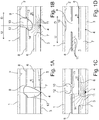
Figures 1A - 1D show a schematic cross-sectional view of a first embodiment of a device according to the invention in four different positions. -
Figures 2A - 2I show different shapes for the plasma passage opening. -
Figures 3A - 3D show a schematic cross-sectional view of a second embodiment of a device according to the invention in four different positions. -
Figure 1A shows asubstrate 1 with asubstrate surface 2. Thesubstrate 1 is typically arranged in a substrate holder (not shown). Atarget 3 is arranged facing thesubstrate surface 2. Thetarget 3 has atarget spot 4 on which alaser beam 5 is directed. Typically thelaser beam 5 is moved over the target and thesubstrate 1 is moved, for example rotated, such that a larger area of thesubstrate surface 2 can be treated. - A
velocity filter 6, which is a disc with a filter passage opening 7, rotates between thesubstrate 1 and thetarget 3. Furthermore aplasma hole plate 8 with aplasma passage opening 9 is arranged between thevelocity filter 6 and thesubstrate 1. The plasma passage opening 9 is arranged stationary relative to thetarget spot 4. So, if thelaser beam 5 is moved over thetarget 3 to treat a larger surface of thesubstrate 1, then the plasma passage opening 9 moves along with thetarget spot 4. - The
pulsed laser 5 is fired at thetarget spot 4 when thefilter passage opening 7 is positioned over thetarget spot 4 and the generatedplasma plume 10 can freely pass thevelocity filter 6 through the filter passage opening 7 (Seefigure 1A ). - After the
laser beam 5 has been fired, theplasma plume 10 will move towards thesubstrate surface 2 via thefilter passage opening 7 and the plasma passage opening 9. - Also
particles 11 will start to be expelled from the surface of thetarget spot 4 in random direction, where thetarget spot 4 can be considered a point source (seefigure 1B ). - A
dividing plane 12, which is perpendicular to the direction of rotation R of thevelocity filter 6 and wherein thetarget spot 4 coincides with thedividing plane 12, divides the space between thesubstrate 1 and thetarget 3 in an upstream part U and a downstream part D. - Because the
velocity filter 6 rotates, the filter passage opening 7 moves away from thetarget spot 4, such thatparticles 11 having a direction into the downstream part D will encounter thevelocity filter 6 sooner, than theparticles 11 having a direction into the upstream part U (i.e. particles 11 having a directional component in the direction of rotation R of the velocity filter 6). - The plasma passage opening 9 has a
downstream section 13 which is larger than theupstream section 14. Due to the smallerupstream section 14, part of theplasma plume 10 will deposit onto theplasma hole plate 8 and will be lost, while the remaining part of theplasma plume 10 passes thedownstream section 13 and will be deposited on thesubstrate surface 2. - When more time passes, the
velocity filter 6 will have rotated further, such that thefilter passage opening 7 has fully passed beyond the dividingplane 12. Anyparticles 11 having a direction towards the downstream part D will be caught by thevelocity filter 6, while some of theparticles 11 having a direction towards the upstream part U could pass through thefilter passage opening 7 but will be caught by the plasma hole plate 8 (seefigure 1C ). - After the emission of
particles 11 from thetarget spot 4 has stopped, thevelocity filter 6 will have rotated even further and has caught a large part of theparticles 11. Theparticles 11 with a direction towards the upstream part and which managed to pass thefilter passage opening 7 will have been caught by theplasma hole plate 8. Theplasma plume 10 will have formed a deposit layer of target material onto the substrate surface 2 (seefigure 1D ). - Thus, by reducing the
plasma passage opening 9 on the upstream part U,particles 11 managing to pass thefilter passage opening 7 will still be filtered by theplasma hole plate 8. This reduces the contamination byparticles 11 of thesubstrate surface 11 and the layer of target material deposited thereon. -
Figures 2A - 2I show different shapes for theplasma passage opening 9 in theplasma hole plate 8 of the device according tofigure 1 . Clearly eachplasma passage opening 9 has anupstream section 13 with a larger surface than thedownstream section 14. Infigure 2D even a shape is proposed, where thedownstream section 14 has a surface area of zero. - It will be clear that the shape of the
plasma passage opening 9 can be determined by a person skilled in the art merely based on an optimization of for example filtering action of theplasma hole plate 8 and the reduction of the depositing rate by theplasma hole plate 8. -
Figure 3A shows a second embodiment of a device according to the invention. Asubstrate 21 with asubstrate surface 22 is arranged in a substrate holder (not shown). Atarget 23 is provided opposite of thesubstrate 21. Atarget spot 24 is irradiated by apulsed laser 25 such that aplasma plume 30 is generated. - Furthermore, a
velocity filter 26 with afilter passage opening 27 is rotated in the direction R between thesubstrate 21 andtarget 23. - Also a
plasma hole plate 28 with aplasma passage opening 29 is arranged between thesubstrate 21 and thevelocity filter 26. In this embodiment theplasma hole plate 28 is also rotated but in direction O opposite of the direction R of thevelocity filter 26. The plasma passage opening 29 can be symmetrical, for example circular. - As shown in
figure 3A , thepulsed laser 25 generate aplasma plume 30 when thefilter passage opening 26 andplasma passage opening 29 align over thetarget spot 24. - A dividing
plane 32, which is perpendicular to the direction of rotation R of thevelocity filter 26 and wherein thetarget spot 24 coincides with the dividingplane 32, divides the space between thesubstrate 21 and thetarget 23 in an upstream part U and a downstream part D. - After the
target spot 24 has been irradiated by thelaser 25, theplasma plume 30 will leave thetarget 23 towards thesubstrate 21 via thefilter passage opening 27 and theplasma passage opening 29. Theplasma plume 30 will be trailed byundesired particles 31. - As the
velocity filter 26 rotates further in the direction R, thefilter passage opening 27 will no longer be aligned over the target spot, which is the point source of theparticles 31, such thatparticles 31 directed towards the downstream part D will be caught by thevelocity filter 26. - At the same time, the
plasma hole plate 28 will have rotated in the opposite direction O, such that theplasma passage opening 29 has, relative to the dividingplane 32, andownstream section 33 with a larger surface area than the surface area of theupstream section 34. Although the reduced size of theupstream section 34 cuts of part of theplasma plume 30, it will also reduce the possibility ofparticles 31 passing through theplasma passage opening 29 and contaminating the substrate surface 22 (seefigure 3B ). - In
figure 3C thevelocity filter 26 has rotated further, such that thefilter passage opening 27 has fully past the dividingplane 32, while theplasma hole plate 28 has rotated further such that theplasma passage opening 29 is also past the dividingplane 32. This ensures that noparticles 31 can reach any longer thesubstrate surface 21 and that all remainingparticles 31 are caught by either thevelocity filter 26 or theplasma hole plate 28. -
Figure 3D shows the position in which theplasma plume 30 has been deposited onto thesubstrate 21 and wherein thelast particles 31 are caught by theplasma hole plate 28.
Claims (8)
- Device for pulsed laser deposition and a substrate with a substrate surface, which device comprises:- a substrate holder for holding the substrate;- a target arranged facing the substrate surface of the substrate;- a velocity filter arranged between the substrate and the target, which velocity filter comprises a rotating body with at least one filter passage opening; and- a pulsed laser directed onto the target at a target spot for generating a plasma plume of target material, wherein the surface of the target at the target spot faces the substrate surfacecharacterized by- a plasma hole plate arranged between the target and the substrate, which plasma hole plate has a plasma passage opening, wherein the plasma passage opening is divided in an upstream section and a downstream section by a dividing plane, which is perpendicular to the direction of rotation of the velocity filter, wherein the target spot coincides with the dividing plane, and wherein the surface area of the upstream section is larger than the surface area of the downstream section at least at the moment of generation of a plasma plume by the pulsed laser.
- Device according to claim 1, wherein the length of the upstream section of the plasma passage opening in the direction of rotation of the velocity filter is larger than the length of the downstream section of the plasma passage opening in the direction of rotation of the velocity filter.
- Device according to claim 1 or 2, wherein the plasma hole plate is arranged between the velocity filter and the substrate.
- Device according to any of the preceding claims, wherein, in use, a part of the generated plasma plume is shielded by the plasma hole plate on the downstream section side of the dividing plane.
- Device according to claim 4, wherein, in use, a larger part of the generated plasma plume is shielded on the downstream section side of the dividing plane than on the upstream section side of the dividing plane.
- Device according to any of the preceding claims, wherein the plasma hole plate rotates in opposite direction compared to the direction of rotation of the velocity filter.
- Device according to any of the preceding claims, wherein the surface of the target at the target spot is parallel to the substrate surface.
- Device according to any of the preceding claims, wherein the plasma passage opening is asymmetrically shaped in relation to the radial direction of the plasma hole plate.
Priority Applications (6)
| Application Number | Priority Date | Filing Date | Title |
|---|---|---|---|
| EP18180369.3A EP3587620A1 (en) | 2018-06-28 | 2018-06-28 | Device for pulsed laser deposition and a substrate with a substrate surface for reduction of particles on the substrate |
| TW108120581A TWI841569B (en) | 2018-06-28 | 2019-06-14 | Device for pulsed laser deposition and a substrate with a substrate surface for reduction of particles on the substrate |
| JP2019112906A JP7506461B2 (en) | 2018-06-28 | 2019-06-18 | Apparatus for pulsed laser deposition for particle reduction on a substrate and substrate having a substrate surface - Patents.com |
| KR1020190075512A KR102805929B1 (en) | 2018-06-28 | 2019-06-25 | Device for pulsed laser depostion and a substrate with a substrate surface for reduction of particles on the substrate |
| US16/451,282 US11655535B2 (en) | 2018-06-28 | 2019-06-25 | Device for pulsed laser deposition and a substrate with a substrate surface for reduction of particles on the substrate |
| CN201910570727.6A CN110656312A (en) | 2018-06-28 | 2019-06-28 | Apparatus for pulsed laser deposition and substrate having a substrate surface |
Applications Claiming Priority (1)
| Application Number | Priority Date | Filing Date | Title |
|---|---|---|---|
| EP18180369.3A EP3587620A1 (en) | 2018-06-28 | 2018-06-28 | Device for pulsed laser deposition and a substrate with a substrate surface for reduction of particles on the substrate |
Publications (1)
| Publication Number | Publication Date |
|---|---|
| EP3587620A1 true EP3587620A1 (en) | 2020-01-01 |
Family
ID=62837604
Family Applications (1)
| Application Number | Title | Priority Date | Filing Date |
|---|---|---|---|
| EP18180369.3A Pending EP3587620A1 (en) | 2018-06-28 | 2018-06-28 | Device for pulsed laser deposition and a substrate with a substrate surface for reduction of particles on the substrate |
Country Status (6)
| Country | Link |
|---|---|
| US (1) | US11655535B2 (en) |
| EP (1) | EP3587620A1 (en) |
| JP (1) | JP7506461B2 (en) |
| KR (1) | KR102805929B1 (en) |
| CN (1) | CN110656312A (en) |
| TW (1) | TWI841569B (en) |
Cited By (3)
| Publication number | Priority date | Publication date | Assignee | Title |
|---|---|---|---|---|
| EP3868916A1 (en) * | 2020-02-19 | 2021-08-25 | Solmates B.V. | Filter for a plasma plume |
| EP3919650A1 (en) | 2020-06-04 | 2021-12-08 | Solmates B.V. | Device for pulsed laser deposition |
| EP3964605A1 (en) | 2020-09-03 | 2022-03-09 | Solmates B.V. | Device for pulsed laser deposition |
Citations (2)
| Publication number | Priority date | Publication date | Assignee | Title |
|---|---|---|---|---|
| JP2001192811A (en) * | 2000-01-17 | 2001-07-17 | Canon Inc | Film forming method and film forming apparatus |
| EP2410074A1 (en) | 2010-07-21 | 2012-01-25 | Solmates B.V. | Heat shield and filter |
Family Cites Families (11)
| Publication number | Priority date | Publication date | Assignee | Title |
|---|---|---|---|---|
| DE69028662T2 (en) | 1989-07-06 | 1997-03-06 | Toyoda Chuo Kenkyusho Kk | Method and device for laser vapor deposition |
| US5411772A (en) * | 1994-01-25 | 1995-05-02 | Rockwell International Corporation | Method of laser ablation for uniform thin film deposition |
| US6805916B2 (en) | 2001-01-17 | 2004-10-19 | Research Foundation Of The City University Of New York | Method for making films utilizing a pulsed laser for ion injection and deposition |
| JP3787719B2 (en) * | 2002-07-05 | 2006-06-21 | 独立行政法人科学技術振興機構 | Method for producing ternary phase diagram thin film and masking mechanism for combinatorial film forming apparatus used therefor |
| JP2005068449A (en) * | 2003-08-25 | 2005-03-17 | Japan Science & Technology Agency | Laser ablation deposition system with high-speed rotary vane filter |
| US8828506B2 (en) * | 2007-02-23 | 2014-09-09 | Picodeon Ltd Oy | Arrangement |
| EP2243855B1 (en) * | 2009-04-22 | 2021-03-03 | Solmates B.V. | Pulsed laser deposition with exchangeable shadow masks |
| FI20096012A0 (en) * | 2009-10-02 | 2009-10-02 | Picodeon Ltd Oy | Method and arrangement for producing crystalline structures |
| JP5356627B2 (en) | 2011-03-11 | 2013-12-04 | シャープ株式会社 | Vapor deposition particle injection apparatus and vapor deposition apparatus |
| EP2722412B1 (en) | 2012-10-17 | 2018-04-25 | Solmates B.V. | Method for depositing a target material onto a sensitive material |
| FI126769B (en) * | 2014-12-23 | 2017-05-15 | Picodeon Ltd Oy | Lighthouse type scanner with a rotating mirror and a circular target |
-
2018
- 2018-06-28 EP EP18180369.3A patent/EP3587620A1/en active Pending
-
2019
- 2019-06-14 TW TW108120581A patent/TWI841569B/en active
- 2019-06-18 JP JP2019112906A patent/JP7506461B2/en active Active
- 2019-06-25 US US16/451,282 patent/US11655535B2/en active Active
- 2019-06-25 KR KR1020190075512A patent/KR102805929B1/en active Active
- 2019-06-28 CN CN201910570727.6A patent/CN110656312A/en active Pending
Patent Citations (2)
| Publication number | Priority date | Publication date | Assignee | Title |
|---|---|---|---|---|
| JP2001192811A (en) * | 2000-01-17 | 2001-07-17 | Canon Inc | Film forming method and film forming apparatus |
| EP2410074A1 (en) | 2010-07-21 | 2012-01-25 | Solmates B.V. | Heat shield and filter |
Cited By (6)
| Publication number | Priority date | Publication date | Assignee | Title |
|---|---|---|---|---|
| EP3868916A1 (en) * | 2020-02-19 | 2021-08-25 | Solmates B.V. | Filter for a plasma plume |
| US11628389B2 (en) | 2020-02-19 | 2023-04-18 | Lam Research Corporation | Filter for a plasma plume |
| US12330102B2 (en) | 2020-02-19 | 2025-06-17 | Lam Researh Corporation | Filter for a plasma plume |
| TWI889760B (en) * | 2020-02-19 | 2025-07-11 | 美商蘭姆研究公司 | Filter for a plasma plume |
| EP3919650A1 (en) | 2020-06-04 | 2021-12-08 | Solmates B.V. | Device for pulsed laser deposition |
| EP3964605A1 (en) | 2020-09-03 | 2022-03-09 | Solmates B.V. | Device for pulsed laser deposition |
Also Published As
| Publication number | Publication date |
|---|---|
| JP7506461B2 (en) | 2024-06-26 |
| CN110656312A (en) | 2020-01-07 |
| TWI841569B (en) | 2024-05-11 |
| TW202012664A (en) | 2020-04-01 |
| KR102805929B1 (en) | 2025-05-14 |
| US11655535B2 (en) | 2023-05-23 |
| US20200002805A1 (en) | 2020-01-02 |
| KR20200001989A (en) | 2020-01-07 |
| JP2020002464A (en) | 2020-01-09 |
Similar Documents
| Publication | Publication Date | Title |
|---|---|---|
| US11655535B2 (en) | Device for pulsed laser deposition and a substrate with a substrate surface for reduction of particles on the substrate | |
| FI126769B (en) | Lighthouse type scanner with a rotating mirror and a circular target | |
| KR20150047457A (en) | Movable masks for thermal and / or kinetic coating systems | |
| EP2799180B1 (en) | Method and device for structuring the surface of a machine element | |
| US7300557B2 (en) | Device for targeted application of deposition material to a substrate | |
| CN103154309A (en) | Ion beam distribution | |
| JP4984070B2 (en) | Film forming method and film forming apparatus | |
| CN105436585B (en) | Target processing equipment and processing method | |
| US11177117B2 (en) | Method for pulsed laser deposition | |
| JP3666055B2 (en) | X-ray generator and X-ray exposure apparatus | |
| EP3919650B1 (en) | Device for pulsed laser deposition | |
| US4484058A (en) | Electron beam hole drilling apparatus | |
| EP3964605A1 (en) | Device for pulsed laser deposition | |
| JPH1030169A (en) | Film forming equipment | |
| KR102827232B1 (en) | Filter for a plasma plume | |
| US20250114873A1 (en) | Method for laser machining a work piece | |
| EP3462035B1 (en) | Method for balancing a rotor of a vacuum pump | |
| JPH0883690A (en) | X-ray generator | |
| JPS6137386A (en) | Electron-beam drilling method and device | |
| Reiße et al. | Reduction of particulate density in BN films prepared by pulsed laser deposition | |
| JPH09148093A (en) | X-ray generator | |
| AT14607U1 (en) | Absorber for a water jet cutting device used in osteotomy | |
| KR20170071075A (en) | chamber for deposition apparatus using laser | |
| JPH02182386A (en) | Energy beam machine |
Legal Events
| Date | Code | Title | Description |
|---|---|---|---|
| PUAI | Public reference made under article 153(3) epc to a published international application that has entered the european phase |
Free format text: ORIGINAL CODE: 0009012 |
|
| STAA | Information on the status of an ep patent application or granted ep patent |
Free format text: STATUS: THE APPLICATION HAS BEEN PUBLISHED |
|
| AK | Designated contracting states |
Kind code of ref document: A1 Designated state(s): AL AT BE BG CH CY CZ DE DK EE ES FI FR GB GR HR HU IE IS IT LI LT LU LV MC MK MT NL NO PL PT RO RS SE SI SK SM TR |
|
| AX | Request for extension of the european patent |
Extension state: BA ME |
|
| STAA | Information on the status of an ep patent application or granted ep patent |
Free format text: STATUS: REQUEST FOR EXAMINATION WAS MADE |
|
| 17P | Request for examination filed |
Effective date: 20200617 |
|
| RBV | Designated contracting states (corrected) |
Designated state(s): AL AT BE BG CH CY CZ DE DK EE ES FI FR GB GR HR HU IE IS IT LI LT LU LV MC MK MT NL NO PL PT RO RS SE SI SK SM TR |
|
| STAA | Information on the status of an ep patent application or granted ep patent |
Free format text: STATUS: EXAMINATION IS IN PROGRESS |
|
| 17Q | First examination report despatched |
Effective date: 20221128 |
|
| RAP1 | Party data changed (applicant data changed or rights of an application transferred) |
Owner name: LAM RESEARCH CORPORATION |
|
| P01 | Opt-out of the competence of the unified patent court (upc) registered |
Effective date: 20231021 |