EP3587181A1 - Transport vehicle - Google Patents
Transport vehicle Download PDFInfo
- Publication number
- EP3587181A1 EP3587181A1 EP19181358.3A EP19181358A EP3587181A1 EP 3587181 A1 EP3587181 A1 EP 3587181A1 EP 19181358 A EP19181358 A EP 19181358A EP 3587181 A1 EP3587181 A1 EP 3587181A1
- Authority
- EP
- European Patent Office
- Prior art keywords
- hook
- stop element
- transport vehicle
- vehicle according
- securing means
- Prior art date
- Legal status (The legal status is an assumption and is not a legal conclusion. Google has not performed a legal analysis and makes no representation as to the accuracy of the status listed.)
- Granted
Links
- 230000008878 coupling Effects 0.000 claims abstract description 7
- 238000010168 coupling process Methods 0.000 claims abstract description 7
- 238000005859 coupling reaction Methods 0.000 claims abstract description 7
- 230000000295 complement effect Effects 0.000 claims description 5
- 230000006978 adaptation Effects 0.000 description 3
- 238000000034 method Methods 0.000 description 2
- 125000006850 spacer group Chemical group 0.000 description 2
- XAGFODPZIPBFFR-UHFFFAOYSA-N aluminium Chemical compound [Al] XAGFODPZIPBFFR-UHFFFAOYSA-N 0.000 description 1
- 229910052782 aluminium Inorganic materials 0.000 description 1
- 230000006872 improvement Effects 0.000 description 1
- 238000003780 insertion Methods 0.000 description 1
- 230000037431 insertion Effects 0.000 description 1
- 230000001788 irregular Effects 0.000 description 1
- 239000000463 material Substances 0.000 description 1
- 230000007246 mechanism Effects 0.000 description 1
- 230000008569 process Effects 0.000 description 1
Images


Classifications
-
- B—PERFORMING OPERATIONS; TRANSPORTING
- B60—VEHICLES IN GENERAL
- B60P—VEHICLES ADAPTED FOR LOAD TRANSPORTATION OR TO TRANSPORT, TO CARRY, OR TO COMPRISE SPECIAL LOADS OR OBJECTS
- B60P7/00—Securing or covering of load on vehicles
- B60P7/06—Securing of load
- B60P7/135—Securing or supporting by load bracing means
-
- B—PERFORMING OPERATIONS; TRANSPORTING
- B60—VEHICLES IN GENERAL
- B60P—VEHICLES ADAPTED FOR LOAD TRANSPORTATION OR TO TRANSPORT, TO CARRY, OR TO COMPRISE SPECIAL LOADS OR OBJECTS
- B60P7/00—Securing or covering of load on vehicles
- B60P7/06—Securing of load
- B60P7/08—Securing to the vehicle floor or sides
- B60P7/0876—Securing to the vehicle floor or sides using restraining net or tarpaulin in contact with the load
Definitions
- the invention relates to a transport vehicle, in particular a truck semi-trailer, with a loading space delimited by side walls, a transport area and possibly a roof area, and with at least one cross-securing device with edge-side stop devices for position-variable fixing of a cross-securing means on opposing longitudinal struts of the longitudinal side walls, wherein the respective stop device has a hook spanning the associated longitudinal strut and a stop element for coupling to the cross-securing means as part of the cross-securing device.
- Transport vehicles and in particular truck trailers, are usually realized today without a fixed structure and generally have so-called stanchions, bow boards or plug-in slats in connection with a plastic tarpaulin as a side wall.
- the stanchions are generally connected laterally to the transport surface and extend predominantly vertically.
- the push-in slats or bow boards are fixed horizontally between the stanchions, for example inserted into pockets formed on the stanchions.
- Comparable bodies can of course also be used with other transport vehicles, especially train trailers.
- a comparable transport vehicle is used in the US 4 161 145 described.
- the longitudinal struts of the longitudinal side walls are not designed as plug-in slats, but rather are each designed as cables or ropes.
- Clamping devices are attached to the cables or ropes. With the aid of the clamping devices, a safety net arranged transversely to the longitudinal extension can be placed in the cargo space in a variable position. Since nowadays transport vehicles and in particular truck trailers are generally equipped with a standardized structure with the stanchions and plug-in slats or bow boards already described, this is again a variant that is not system-compatible and does not permit compatibility.
- the procedure is such that the stop device is not only equipped with a hook spanning the respective longitudinal strut.
- a corresponding locking element for the hook is also provided, which is a clamping lever and in particular an eccentric lever.
- the hook is releasably attached to the relevant longitudinal strut.
- the hook and also the stop element as part of the stop device fixed correctly on the associated longitudinal strut and can be detached therefrom.
- the coupling with the cross-securing means as part of the cross-securing device is not always easy to implement. Because the cross-securing means can be a single belt, a multiple belt or a safety net individually or in combination, which must be hooked into an opening of the stop element, for example with a hook.
- the invention is based on the technical problem of further developing such a transport vehicle in such a way that the handling and, in particular, the coupling of the stop device to the associated cross-securing means for the implementation of the cross-securing device is simple, quick and problem-free.
- a generic transport vehicle within the scope of the invention is characterized in that the stop element can be swiveled in and out relative to the hook fixed on the longitudinal strut.
- an axis of rotation for the pivoting movement of the stop element relative to the hook is generally arranged in the region of an upper edge of the longitudinal strut.
- the stop element is, as it were, deflected upwards in comparison to the hook, an associated angle opening in the direction of the transport surface of the transport vehicle.
- the stop element is designed to be lockable with respect to the hook.
- To lock the stop element can be equipped with a locking element.
- the locking element in turn interacts with a locking recess on the hook.
- the stop element can be pivoted relative to the hook without any problems, for example in order to be able to attach the transverse securing means to it without difficulty.
- the cross-securing means can be connected to the stop element without any problems, especially if the stop element is in its position pivoted relative to the hook. After the cross securing means has consequently been coupled to the stop element in the pivoted-down position, the stop element can then be pivoted onto the hook fixed on the longitudinal strut. At the same time, the locking element locking the stop element by its engagement in the locking recess on the hook ensures that the cross-securing means is properly fixed to the relevant longitudinal strut in the desired position.
- the hook which can be fixed on the longitudinal strut is equipped with an extension arm for mounting the stop element thereon.
- This means that the mostly inverted U-shaped hook has on its side facing the cargo space inwards or on the corresponding leg of the above-mentioned boom.
- the boom in turn serves to mount the stop element and consequently also to define the associated axis of rotation which is arranged in the region of the upper edge of the longitudinal strut.
- the boom is largely U-shaped.
- the boom as a whole is designed in such a way that it is open towards the loading space.
- the stop element can also be U-shaped to complement the boom. In this way, the overall design can be made such that the stop element overlaps the boom in the pivoted state on the hook. This means that the U-shaped boom, which is open towards the loading space, is supported by a likewise U-shaped and complementary stop element in overlapped in the pivoted state, the stop element being opposite, that is to say open towards the longitudinal strut.
- the boom and the stop element when swiveled together, form a cuboid that is open on the end face, or are designed as a cuboid in combination and in the swiveled-in state.
- a particularly compact and deformation-free stop device for attaching the cross-securing means is made available which, moreover, can be positioned variably on the associated longitudinal strut via the hook is set.
- the stop element pivotable with respect to the hook can also be equipped with at least one lateral extension. Usually two side extensions are provided.
- the invention proposes that the stop element and / or the two extensions are each equipped with receptacles for the fastening element of the cross-securing means which can be releasably engaged therein.
- the fastener of the cross-securing means is the hook mentioned above or the adapter as in the EP 3 154 820 B1 is described in detail.
- the extension or the two extensions are generally connected at an angle to the stop element. This makes it possible not only to orient the cross-securing means, as it were, vertically in comparison to the longitudinal struts in the interior of the loading space, but also the angular arrangement of the two extensions of the Stop element with the associated receptacles for the fasteners of the cross-securing means also opens up the possibility of placing the cross-securing means in the interior of the loading space at an incline. As a result, even complex goods that are to be transported on the transport surface, such as barrels or other irregular objects, can be transported and secured properly.
- the invention proposes that a counter-hook correspond to the respective hook. This allows both hooks to hold the longitudinal strut between them.
- the two hooks can also be moved relative to one another to adapt to different longitudinal struts.
- the two hooks can each be secured against one another after an end position has been reached, so that the stop device cannot become detached from the longitudinal strut.
- the two hooks that is to say the actual hook and the counter hook, are generally each U-shaped.
- the longitudinal strut is usually rectangular in cross section.
- the two hooks with their U-shape can be adapted to the associated longitudinal strut.
- the hook and the counter hook are optionally designed to be interchangeable in order to provide an adaptation to different longitudinal struts or different depths of the longitudinal struts.
- the longitudinal struts generally have a matching depth and only different widths, it is sufficient usually the possibility of adapting to different longitudinal struts in such a way that the two hooks can be moved relative to each other.
- the cross-securing means is one which is equipped with at least two opposing edge-side fastening means.
- the fasteners can be releasably locked in the associated receptacles in the stop element or the corresponding extension.
- the cross-securing means can in principle be rigid. As a rule, however, the cross-securing means is flexible.
- embodiments such as, for example, a single belt, a multiple belt, a safety net, individually or in combination, are recommended, as will be explained in more detail with reference to the description of the figures.
- the stop device is essentially composed of the hook extending over the associated longitudinal strut and the stop element designed to be pivotable on and off relative to the hook fixed on the longitudinal strut.
- the stop element or associated extensions of the stop element are equipped with recesses in which the cross-securing means releasably engages with fastening elements.
- the transverse securing means can be coupled to the stop element, for example when the stop element is pivoted away from the hook. After that, that will be The stop element is pivoted to the hook and locked with the hook, so that as a rule the flexible transverse securing means is also tensioned and assumes its desired shape.
- the stop element which can be swiveled in and out, functions as an overall tensioning lever mechanism with respect to the hook fixed on the longitudinal strut and ensures that the adapter or generally a fastening element of the cross-securing means takes up as little space as possible in the loading space. This also avoids damage from, for example, bumping during loading. Loading is also simplified overall because the adapter or the fastening element does not interfere with this process. All of this is particularly easy, reliable and in a few simple steps, so that the main advantages can be seen here.
- a transport vehicle which is a truck trailer.
- a so-called "curtainsider” is shown, the two longitudinal side walls 1 of which are equipped with a sliding tarpaulin 2.
- the truck trailer shown can be loaded and unloaded from the side, for example.
- the two side walls or longitudinal side walls define a cargo space 1, 3, 4, 5 delimited therefrom rear side wall 5 additionally defined and defined in the form of loading flaps.
- this is only an example and not restrictive. Because it can be the same in the Fig. 1 shown transport vehicle basically act as a train trailer, but this is not shown.
- the two longitudinal side walls 1 have vertical struts or stanchions 6 arranged on the edge of the transport surface 3.
- vertical struts or stanchions 6 each have a plurality of longitudinal struts 7 or bow boards which extend predominantly horizontally.
- the Fig. 1 also makes it clear that the truck semi-trailer additionally with a cross-securing device 8, 9; 10, 9 is equipped.
- the cross-securing device 8, 9; 10, 9 in turn is composed of a cross-securing means 8, 10 and edge-side stop devices 9.
- Common to both transverse securing means 8, 10 is that they are each designed to be flexible and not rigid. As a result, any slipping of the load observed on the transport surface 3 does not result in damage to the relevant cross-securing means 8, 10 and thus also does not result in damage to the cross-securing device 8, 9; 10, 9.
- the cross-securing means 8 is actually a safety net 8 as shown in FIG Fig. 1 and 3 is indicated in detail.
- the further transverse securing means 10 is a multiple belt 10, which is only in the Fig. 1 is reproduced.
- the two transverse securing means 8, 10 are each detachably coupled to the edge-side stop devices 9, which in turn are releasably secured to the longitudinal struts 7.
- the respective cross-securing means 8, 10 and consequently also the cross-securing device 8, 9; 10, 9 determine overall variable position on the opposite longitudinal struts 7 of the longitudinal side walls 1.
- the respective stop device 9 can be in practically any longitudinal position along the in Fig. 1 indicated longitudinal direction L along the associated longitudinal strut 7 are moved and fixed. That is, not only one in the scope of the invention Fig. 1 shown and largely oriented transversely to the respective longitudinal side walls 1 orientation of the transverse securing means 8, 10 possible.
- the cross-securing means 8, 10 can in principle also run "at an angle", as is the case in FIG Fig. 1 is indicated by dash-dotted lines.
- the loading space 1, 3, 4, 5 can be flexibly segmented in its longitudinal direction L, because the relevant cross-securing means 8, 10 with the respectively associated stop devices 9 can be variably positioned on the opposite longitudinal struts 7 of the loading space 1, 3, 4, 5 can be set. In this way, changing sizes of the load can be easily mapped and the load is nevertheless securely secured.
- the realized stop device 9 has a hook 11 which overlaps the respective longitudinal strut 7.
- both a hook 11 arranged on the head side of the longitudinal strut 7 and an associated counter hook 12 are realized.
- Both hooks 11, 12 are each U-shaped in the exemplary embodiment. This can be attributed to the fact that the longitudinal strut 7 is designed as a rectangular hollow profile rod, which is or can be made, for example, of aluminum (or also of plastic).
- the two hooks 11, 12 are designed to be displaceable relative to one another. They also have the same or complementary U-shaped design.
- the relative displaceability is realized in the exemplary embodiment, and not in a restrictive manner, in such a way that the hook 11 placed on the head side of the longitudinal strut 7 is additionally equipped with a bracket 14, against which a stop element 13 is pivotably mounted, taking into account an axis of rotation 15.
- the hook 11 initially has the connected boom 14.
- the boom 14 is in turn equipped with a guide for the counter-hook 12, which can be displaced in contrast.
- the counter hook 12 in one Fig. 2 carry out the indicated shift along the boom 14 and the previously mentioned adaptation to the cross section of the longitudinal strut 7 can be realized.
- the counter hook 12 can be moved in a vertical direction V in the exemplary embodiment and not in a restrictive manner.
- the counter hook 12 can be releasably fixed relative to the bracket 14, which in turn is firmly coupled to the hook 11.
- spacers 16 on the inside of the mentioned hooks 11, 12 ensure in this connection that also differently designed longitudinal struts 7 are properly fixed.
- the spacers 16 may for this purpose additionally be made of a rubber-like material in order to enable the stop device 9 to be secured in a non-slip manner in the desired position in the longitudinal direction L of the loading space 1, 3, 4, 5 on the associated longitudinal strut 7, as has already been described in the introduction.
- the stop element 13 can be swiveled in and out relative to the hook 11 fixed on the longitudinal strut 7.
- the axis of rotation 15 of the stop element 13 realized in this context is located opposite the hook 11 in the region of an upper edge of the longitudinal strut 7, as can be seen in particular when comparing the illustration in FIGS Figures 2 and 3 recognizes.
- the Fig. 2 the pivoted state of the stop element 13 relative to the hook 11, whereas in the Fig. 3 the stop element 3 is pivoted onto the hook 11.
- the stop element 13 is pivoted in and out relative to the arm 14, which in turn is connected to the hook 11.
- the stop element 13 is also designed to be lockable with respect to the hook 11.
- the stop element 13 has a locking element 17 which is displaceable against spring force and which is best used in the Fig. 5 recognizes.
- the latching element 17 interacts with a latching recess 18 on the hook or on its arm 14 Fig. 2 clear.
- the stop element 13 can be releasably locked with the hook 11 or its extension 14 and consequently the longitudinal strut 7.
- the design in the exemplary embodiment is such that the stop element 13 is opposite the hook fixed on the longitudinal strut 7 11 carries out a pivoting movement such that the stop element 13 is pivoted relative to the hook 11 by an angle ⁇ which opens in the direction of the transport surface 3 of the loading space 1, 3, 4, 5.
- swivel angles ⁇ of approximately 30 ° to 40 ° are observed in this connection, which result from the fact that the boom 14 with the corresponding and in the Fig. 4 shown stops 19 is equipped for the stop element 13.
- the boom 14 is connected to the hook 11 on the inside of the loading space for mounting the stop element 13.
- the boom 14 is largely U-shaped in cross section and opened towards the loading space 1, 3, 4, 5 or towards its bottom surface 3, as can be seen in particular in the top view or sectional view according to FIG Fig. 4 recognizes.
- the stop element 13 is complementary to the bracket 14 also U-shaped.
- the stop element 13 is designed such that it engages over the boom 14 in the pivoted-in state, as in FIG Fig. 4 is shown. In this way, the boom 14 and the stop element 13, when the stop element 13 is in the pivoted-in state, as a whole define a hollow cuboid with a rectangular cross section, which is designed to be particularly stable.
- the stop element 13 is equipped with at least one lateral extension 20.
- two lateral extensions 20 are provided, which are each connected at an angle to the stop element 13.
- the two extensions 20 in connection with the stop element 13 are designed trapezoidal in cross section.
- the trapeze in question or the Trapezoidal shape also has a mirror-symmetrical design compared to one in the Fig. 4 indicated plane of symmetry S.
- both the stop element 13 and the extensions 20 on both sides are each equipped with receptacles 21 for fastening elements 22 of the transverse securing means 8, 10 which can be detachably engaged therein.
- the relevant cross-securing means 8, 10 can first be releasably coupled to the stop element 13 with this or one or both extensions 20 with the aid of the fastening element 22 in the pivoted-off state.
- the stop element 13 can be pivoted onto the hook 11 or its extension 14 and locked with it.
- the transverse securing means 8, 10 is ready for use and, at the same time, is oriented as desired relative to the loading space 1, 3, 4, 5.
- the extensions 20 connected at an angle to the stop element 13 with their associated recesses 21 basically even open one in the Fig. 1 and 4 indicated oblique course of the relevant cross-securing means 8, 10.
- the oblique course corresponds to an angle ⁇ with respect to the longitudinal strut 7 oriented in the longitudinal direction L, which according to the embodiment can be approximately 40 ° to 50 °. Of course, this does not apply restrictively (cf. Fig. 4 ).
Landscapes
- Engineering & Computer Science (AREA)
- Transportation (AREA)
- Mechanical Engineering (AREA)
- Fittings On The Vehicle Exterior For Carrying Loads, And Devices For Holding Or Mounting Articles (AREA)
Abstract
Gegenstand ist ein Transportfahrzeug, insbesondere LKW-Auflieger mit einem von Bordwänden (1, 4, 5), einer Transportfläche (3) sowie gegebenenfalls einer Dachfläche umgrenzten Laderaum (1, 3, 4, 5) und mit wenigstens einer Quer-Sicherungsvorrichtung (8. 9; 10, 9) mit randseitigen Anschlagvorrichtungen (9) zur positionsvariablen Festlegung eines Quer-Sicherungsmittels (8, 10) an sich gegenüberliegenden Längsstreben (7) der Längsbordwände (1). Die jeweilige Anschlagvorrichtung (9) weist einen die zugehörige Längsstrebe (7) übergreifenden Haken (11) sowie ein Anschlagelement (13) zur Kupplung mit dem Quer-Sicherungsmittel (8, 10) auf. Erfindungsgemäß ist das Anschlagelement (13) gegenüber dem an der Längsstrebe (7) festgelegten Haken (11) an- und abschwenkbar ausgebildet.The subject matter is a transport vehicle, in particular a truck trailer with a loading space (1, 3, 4, 5) and at least one transverse securing device (8) that is delimited by side walls (1, 4, 5), a transport area (3) and possibly a roof area 9; 10, 9) with edge-side stop devices (9) for the position-variable fixing of a transverse securing means (8, 10) on opposite longitudinal struts (7) of the side walls (1). The respective stop device (9) has a hook (11) which overlaps the associated longitudinal strut (7) and a stop element (13) for coupling to the transverse securing means (8, 10). According to the invention, the stop element (13) is designed to be pivotable on and off with respect to the hook (11) fixed on the longitudinal strut (7).
Description
Die Erfindung betrifft ein Transportfahrzeug, insbesondere einen LKW-Auflieger, mit einem von Bordwänden, einer Transportfläche sowie gegebenenfalls einer Dachfläche umgrenzten Laderaum, und mit wenigstens einer Quer-Sicherungsvorrichtung mit randseitigen Anschlagvorrichtungen zur positionsvariablen Festlegung eines Quer-Sicherungsmittels an sich gegenüberliegenden Längsstreben der Längsbordwände, wobei die jeweilige Anschlagvorrichtung einen die zugehörige Längsstrebe übergreifenden Haken sowie ein Anschlagelement zur Kopplung mit dem Quer-Sicherungsmittel als Bestandteil der Quer-Sicherungsvorrichtung aufweist.The invention relates to a transport vehicle, in particular a truck semi-trailer, with a loading space delimited by side walls, a transport area and possibly a roof area, and with at least one cross-securing device with edge-side stop devices for position-variable fixing of a cross-securing means on opposing longitudinal struts of the longitudinal side walls, wherein the respective stop device has a hook spanning the associated longitudinal strut and a stop element for coupling to the cross-securing means as part of the cross-securing device.
Üblicherweise werden Transportfahrzeuge und insbesondere LKW-Auflieger heutzutage ohne festen Aufbau realisiert und weisen als Bordwand in der Regel sogenannte Rungen, Spriegelbretter oder Einstecklatten in Verbindung mit einer Kunststoffplane als seitliche Begrenzung auf. Die Rungen sind dabei im Allgemeinen seitlich an die Transportfläche angeschlossen und erstrecken sich überwiegend vertikal. Demgegenüber werden die Einstecklatten bzw. Spriegelbretter zwischen den Rungen horizontal festgelegt, beispielsweise in an den Rungen ausgebildete Taschen eingesteckt. Vergleichbare Aufbauten können selbstverständlich auch bei anderen Transportfahrzeugen, insbesondere Zuganhängern, zum Einsatz kommen.Transport vehicles, and in particular truck trailers, are usually realized today without a fixed structure and generally have so-called stanchions, bow boards or plug-in slats in connection with a plastic tarpaulin as a side wall. The stanchions are generally connected laterally to the transport surface and extend predominantly vertically. In contrast, the push-in slats or bow boards are fixed horizontally between the stanchions, for example inserted into pockets formed on the stanchions. Comparable bodies can of course also be used with other transport vehicles, especially train trailers.
Im Rahmen der
Ein vergleichbares Transportfahrzeug wird in der
Im gattungsbildenden und auf die Anmelderin zurückgehenden Stand der Technik nach der
Das hat sich in der Praxis zwar bewährt, lässt allerdings noch Raum für Verbesserungen. Denn es hat sich herausgestellt, dass auf diese Weise der Haken und auch das Anschlagelement als Bestandteil der Anschlagvorrichtung zwar einwandfrei an der zugehörigen Längsstrebe festgelegt und hiervon wieder gelöst werden können. Allerdings ist die Kopplung mit dem Quer-Sicherungsmittel als Bestandteil der Quer-Sicherungsvorrichtung nicht immer einfach zu realisieren. Denn bei dem Quer-Sicherungsmittel kann es sich um einen Einfachgurt, einen Mehrfachgurt oder auch ein Sicherungsnetz einzeln oder in Kombination handeln, die mit beispielsweise einem Haken in eine Öffnung des Anschlagelementes eingehängt werden müssen.While this has proven itself in practice, there is still room for improvement. Because it has been found that in this way the hook and also the stop element as part of the stop device fixed correctly on the associated longitudinal strut and can be detached therefrom. However, the coupling with the cross-securing means as part of the cross-securing device is not always easy to implement. Because the cross-securing means can be a single belt, a multiple belt or a safety net individually or in combination, which must be hooked into an opening of the stop element, for example with a hook.
Da bei der Festlegung des genannten Quer-Sicherungsmittels beispielsweise mit einem Haken in der Öffnung des Anschlagelementes das Anschlagelement zusammen mit dem Haken bei der bekannten Lehre nach der
Der Erfindung liegt das technische Problem zugrunde, ein derartiges Transportfahrzeug so weiterzuentwickeln, dass die Handhabung und insbesondere die Kopplung der Anschlagvorrichtung mit dem zugehörigen Quer-Sicherungsmittel zur Realisierung der Quer-Sicherungsvorrichtung einfach, schnell und problemlos gelingt.The invention is based on the technical problem of further developing such a transport vehicle in such a way that the handling and, in particular, the coupling of the stop device to the associated cross-securing means for the implementation of the cross-securing device is simple, quick and problem-free.
Zur Lösung dieser technischen Problemstellung ist ein gattungsgemäßes Transportfahrzeug im Rahmen der Erfindung dadurch gekennzeichnet, dass das Anschlagelement gegenüber dem an der Längsstrebe festgelegten Haken an- und abschwenkbar ausgebildet ist.To solve this technical problem, a generic transport vehicle within the scope of the invention is characterized in that the stop element can be swiveled in and out relative to the hook fixed on the longitudinal strut.
In diesem Zusammenhang ist eine Drehachse für die Schwenkbewegung des Anschlagelementes gegenüber dem Haken im Allgemeinen im Bereich einer oberen Kante der Längsstrebe angeordnet. Auf diese Weise wird das Anschlagelement im Vergleich zu dem Haken gleichsam nach oben hin weggeschenkt, wobei sich ein zugehöriger Winkel in Richtung auf die Transportfläche des Transportfahrzeuges hin öffnet. Außerdem hat es sich bewährt, wenn das Anschlagelement gegenüber dem Haken verriegelbar ausgebildet ist. Zur Verriegelung kann das Anschlagelement mit einem Rastelement ausgerüstet sein. Das Rastelement wechselwirkt seinerseits mit einer Rastausnehmung am Haken. Dadurch kann das Anschlagelement gegenüber dem Haken problemlos abgeschwenkt werden, um beispielsweise das Quer-Sicherungsmittel hieran unschwer festlegen zu können.In this context, an axis of rotation for the pivoting movement of the stop element relative to the hook is generally arranged in the region of an upper edge of the longitudinal strut. In this way, the stop element is, as it were, deflected upwards in comparison to the hook, an associated angle opening in the direction of the transport surface of the transport vehicle. In addition, it has proven useful if the stop element is designed to be lockable with respect to the hook. To lock the stop element can be equipped with a locking element. The locking element in turn interacts with a locking recess on the hook. As a result, the stop element can be pivoted relative to the hook without any problems, for example in order to be able to attach the transverse securing means to it without difficulty.
Die abgeschwenkte Position des Anschlagelementes gegenüber dem Haken stellt dabei sicher, dass in diesem Zusammenhang auch relativ komplexe und am Quer-Sicherungselement wahlweise angebrachte Adapter einwandfrei in eine Öffnung am Anschlagelement eingeführt und hierin lösbar verriegelt werden können. Wie zuvor bereits erläutert, kann an dieser Stelle beispielhaft ein Adapter zum Einsatz kommen, wie er im Zusammenhang mit der zuvor bereits zitierten
Jedenfalls lässt sich das Quer-Sicherungsmittel problemlos mit dem Anschlagelement verbinden, insbesondere wenn sich das Anschlagelement in seiner gegenüber dem Haken abgeschwenkten Position befindet. Nachdem folglich das Quer-Sicherungsmittel mit dem Anschlagelement in der abgeschwenkten Position gekoppelt worden ist, lässt sich das Anschlagelement anschließend an den an der Längsstrebe festgelegten Haken anschwenken. Zugleich sorgt in diesem Zusammenhang das das Anschlagelement verriegelnde Rastelement durch seinen Eingriff in die Rastausnehmung am Haken dafür, dass das Quer-Sicherungsmittel einwandfrei an der betreffenden Längsstrebe in der gewünschten Position festgelegt ist.In any case, the cross-securing means can be connected to the stop element without any problems, especially if the stop element is in its position pivoted relative to the hook. After the cross securing means has consequently been coupled to the stop element in the pivoted-down position, the stop element can then be pivoted onto the hook fixed on the longitudinal strut. At the same time, the locking element locking the stop element by its engagement in the locking recess on the hook ensures that the cross-securing means is properly fixed to the relevant longitudinal strut in the desired position.
Der an der Längsstrebe festlegbare Haken ist zu diesem Zweck und im Detail laderauminnenseitig mit einem Ausleger zur Lagerung des Anschlagelementes hieran ausgerüstet. Das heißt, der zumeist umgekehrt U-förmige Haken verfügt an seiner dem Laderaum nach innen hin zugewandten Seite bzw. an dem entsprechenden Schenkel über den zuvor angesprochenen Ausleger. Der Ausleger dient seinerseits zur Lagerung des Anschlagelementes und folglich auch zur Definition der zugehörigen und im Bereich der oberen Kante der Längsstrebe angeordneten Drehachse.For this purpose and in detail on the inside of the cargo hold, the hook which can be fixed on the longitudinal strut is equipped with an extension arm for mounting the stop element thereon. This means that the mostly inverted U-shaped hook has on its side facing the cargo space inwards or on the corresponding leg of the above-mentioned boom. The boom in turn serves to mount the stop element and consequently also to define the associated axis of rotation which is arranged in the region of the upper edge of the longitudinal strut.
In diesem Zusammenhang ist der Ausleger größtenteils U-förmig ausgebildet. Außerdem ist der Ausleger insgesamt so ausgestaltet, dass er zum Laderaum hin geöffnet ist. Das Anschlagelement kann demgegenüber komplementär zum Ausleger ebenfalls U-förmig ausgebildet sein. Auf diese Weise lässt sich die Auslegung insgesamt so treffen, dass das Anschlagelement in angeschwenktem Zustand an den Haken den Ausleger übergreift. Das heißt, der zum Laderaum hin geöffnete und U-förmige Ausleger wird von einem ebenfalls U-förmigen und komplementären Anschlagelement in angeschwenktem Zustand übergriffen, wobei das Anschlagelement entgegengesetzt, das heißt zur Längsstrebe hin geöffnet ist.In this context, the boom is largely U-shaped. In addition, the boom as a whole is designed in such a way that it is open towards the loading space. In contrast, the stop element can also be U-shaped to complement the boom. In this way, the overall design can be made such that the stop element overlaps the boom in the pivoted state on the hook. This means that the U-shaped boom, which is open towards the loading space, is supported by a likewise U-shaped and complementary stop element in overlapped in the pivoted state, the stop element being opposite, that is to say open towards the longitudinal strut.
Dadurch formen der Ausleger und das Anschlagelement in angeschwenktem Zustand zusammengenommen einen jeweils stirnseitig offenen Quader bzw. sind in Kombination und im angeschwenktem Zustand quaderförmig ausgelegt. In Verbindung mit der im angeschwenktem Zustand zugleich realisierten Verriegelung zwischen dem Anschlagelement und dem Haken bzw. dem Ausleger wird dadurch eine besonders kompakte und verformungsfreie Anschlagvorrichtung zur Anbringung des Quer-Sicherungsmittel zur Verfügung gestellt, die über den Haken darüber hinaus einwandfrei an der zugehörigen Längsstrebe positionsvariabel festgelegt ist.As a result, the boom and the stop element, when swiveled together, form a cuboid that is open on the end face, or are designed as a cuboid in combination and in the swiveled-in state. In connection with the locking between the stop element and the hook or the boom, which is also realized in the swiveled-in state, a particularly compact and deformation-free stop device for attaching the cross-securing means is made available which, moreover, can be positioned variably on the associated longitudinal strut via the hook is set.
Das gegenüber dem Haken verschwenkbare Anschlagelement kann darüber hinaus noch mit wenigstens einer seitlichen Verlängerung ausgerüstet sein. Meistens sind zwei seitliche Verlängerungen vorgesehen. Außerdem schlägt die Erfindung vor, dass das Anschlagelement und/oder die beiden Verlängerungen jeweils mit Aufnahmen für das hierin lösbar eingreifende Befestigungselement des Quer-Sicherungsmittels ausgerüstet sind. Bei dem Befestigungselement des Quer-Sicherungsmittels handelt es sich um den zuvor bereits angesprochenen Haken oder auch den Adapter, wie er in der
Die Verlängerung bzw. die beiden Verlängerungen sind im Allgemeinen jeweils winklig an das Anschlagelement angeschlossen. Dadurch besteht die Möglichkeit, das Quer-Sicherungsmittel nicht nur gleichsam senkrecht im Vergleich zu den Längsstreben im Innern des Laderaumes zu orientieren, sondern die winklige Anordnung der beiden Verlängerungen des Anschlagelementes mit den zugehörigen Aufnahmen für die Befestigungselemente des Quer-Sicherungsmittels eröffnet darüber hinaus noch die Möglichkeit, das Quer-Sicherungsmittel insgesamt schräg verlaufend im Innern des Laderaums zu platzieren. Dadurch können auch beispielsweise komplexe und auf der Transportfläche zu transportierende Güter wie beispielsweise Fässer oder andere unregelmäßige Gegenstände einwandfrei transportiert und gesichert werden.The extension or the two extensions are generally connected at an angle to the stop element. This makes it possible not only to orient the cross-securing means, as it were, vertically in comparison to the longitudinal struts in the interior of the loading space, but also the angular arrangement of the two extensions of the Stop element with the associated receptacles for the fasteners of the cross-securing means also opens up the possibility of placing the cross-securing means in the interior of the loading space at an incline. As a result, even complex goods that are to be transported on the transport surface, such as barrels or other irregular objects, can be transported and secured properly.
Um die Festlegung der Anschlagvorrichtung mit dem Haken an der zugehörigen Längsstrebe zu optimieren, schlägt die Erfindung vor, dass zu dem jeweiligen Haken ein Gegenhaken korrespondiert. Dadurch können beide Haken zwischen sich die Längsstrebe aufnehmen. Um an dieser Stelle eine Anpassung an unterschiedlich gestaltete Längsstreben hinsichtlich ihrer Querschnittsform, Breite und Tiefe zu erreichen, lassen sich die beiden Haken darüber hinaus zur Anpassung an unterschiedliche Längsstreben relativ zueinander verschieben. In diesem Zusammenhang versteht es sich, dass die beiden Haken nach Erreichen einer Endposition jeweils gegeneinander gesichert werden können, damit sich die Anschlagvorrichtung von der Längsstrebe nicht lösen kann.In order to optimize the fixing of the stop device with the hook on the associated longitudinal strut, the invention proposes that a counter-hook correspond to the respective hook. This allows both hooks to hold the longitudinal strut between them. In order to achieve an adaptation to differently designed longitudinal struts with regard to their cross-sectional shape, width and depth at this point, the two hooks can also be moved relative to one another to adapt to different longitudinal struts. In this context, it goes without saying that the two hooks can each be secured against one another after an end position has been reached, so that the stop device cannot become detached from the longitudinal strut.
Schlussendlich sind die beiden Haken, das heißt der eigentliche Haken und der Gegenhaken, im Allgemeinen jeweils U-förmig ausgebildet. Außerdem ist die Längsstrebe meistens im Querschnitt rechteckförmig ausgebildet. Dadurch können die beiden Haken mit ihrer U-Form an die zugehörige Längsstrebe angepasst werden. Es versteht sich, dass der Haken und der Gegenhaken gegebenenfalls austauschbar gestaltet sind, um eine Anpassung an unterschiedliche Längsstreben bzw. unterschiedliche Tiefen der Längsstreben zur Verfügung zu stellen. Da die Längsstreben jedoch im allgemeinen über eine übereinstimmende Tiefe und lediglich unterschiedliche Breiten verfügen, reicht in der Regel die Möglichkeit zur Anpassung an unterschiedliche Längsstreben derart aus, dass sich die beiden Haken zueinander verschieben lassen.Finally, the two hooks, that is to say the actual hook and the counter hook, are generally each U-shaped. In addition, the longitudinal strut is usually rectangular in cross section. As a result, the two hooks with their U-shape can be adapted to the associated longitudinal strut. It goes without saying that the hook and the counter hook are optionally designed to be interchangeable in order to provide an adaptation to different longitudinal struts or different depths of the longitudinal struts. However, since the longitudinal struts generally have a matching depth and only different widths, it is sufficient usually the possibility of adapting to different longitudinal struts in such a way that the two hooks can be moved relative to each other.
Bei dem Quer-Sicherungsmittel handelt es sich schließlich um ein solches, welches mit wenigstens zwei sich gegenüberliegenden randseitigen Befestigungsmitteln ausgerüstet ist. Die Befestigungsmittel lassen sich dabei lösbar in den zugehörigen Aufnahmen im Anschlagelement oder der korrespondierenden Verlängerung verriegeln. Darüber hinaus kann das Quer-Sicherungsmittel grundsätzlich starr ausgelegt sein. Im Regelfall ist das Quer-Sicherungsmittel jedoch flexibel ausgebildet. Hier empfehlen sich Ausführungsformen wie beispielsweise ein Einfachgurt, ein Mehrfachgurt, ein Sicherungsnetz einzeln oder in Kombination, wie dies mit Bezug zur Figurenbeschreibung insgesamt noch näher erläutert wird.Finally, the cross-securing means is one which is equipped with at least two opposing edge-side fastening means. The fasteners can be releasably locked in the associated receptacles in the stop element or the corresponding extension. In addition, the cross-securing means can in principle be rigid. As a rule, however, the cross-securing means is flexible. Here, embodiments such as, for example, a single belt, a multiple belt, a safety net, individually or in combination, are recommended, as will be explained in more detail with reference to the description of the figures.
Im Ergebnis wird ein Transportfahrzeug zur Verfügung gestellt, welches eine einfache und funktionssichere Kopplung der Quer-Sicherungsvorrichtung mit der jeweils zugehörigen randseitigen Anschlagvorrichtung ermöglicht. Dazu setzt sich die Anschlagvorrichtung im Wesentlichen aus dem die zugehörige Längsstrebe übergreifenden Haken sowie dem gegenüber dem an der Längsstrebe festgelegten Haken an- und abschwenkbar ausgebildeten Anschlagelement zusammen. Das Anschlagelement bzw. zugehörige Verlängerungen des Anschlagelementes sind zu diesem Zweck mit Ausnehmungen ausgerüstet, in welche das Quersicherungsmittel mit Befestigungselementen lösbar eingreift.As a result, a transport vehicle is made available which enables a simple and functionally reliable coupling of the cross-securing device to the associated edge-side stop device. For this purpose, the stop device is essentially composed of the hook extending over the associated longitudinal strut and the stop element designed to be pivotable on and off relative to the hook fixed on the longitudinal strut. For this purpose, the stop element or associated extensions of the stop element are equipped with recesses in which the cross-securing means releasably engages with fastening elements.
Auf diese Weise lässt sich das Quer-Sicherungsmittel beispielsweise in abgeschwenktem Zustand des Anschlagelementes gegenüber dem Haken mit dem Anschlagelement koppeln. Im Anschluss daran wird dann das Anschlagelement an den Haken angeschwenkt und mit dem Haken verriegelt, so dass hierbei im Regelfall zugleich auch das flexible Quer-Sicherungsmittel gespannt wird und seine gewünschte Form einnimmt.In this way, the transverse securing means can be coupled to the stop element, for example when the stop element is pivoted away from the hook. After that, that will be The stop element is pivoted to the hook and locked with the hook, so that as a rule the flexible transverse securing means is also tensioned and assumes its desired shape.
Auf diese Weise können einerseits ganz unterschiedlich ausgelegte Längsstreben mit verschiedenen Querschnitten und Abmessungen zum Einsatz kommen. Außerdem fungiert das an- und abschwenkbar gestaltete Anschlagelement gegenüber dem an der Längsstrebe festgelegten Haken als insgesamt Spannhebelmechanik und sorgt dafür, dass der Adapter oder allgemein ein Befestigungselement des Quer-Sicherungsmittels so wenig Platz wie möglich im Laderaum einnimmt. Dadurch wird zugleich auch eine Beschädigung durch beispielsweise Anecken bei Beladung vermieden. Auch wird das Beladen insgesamt vereinfacht, weil der Adapter bzw. das Befestigungselement diesen Vorgang nicht stört. Das alles gelingt besonders einfach, funktionssicher und mit wenigen Handgriffen, so dass hierin die wesentlichen Vorteile zu sehen sind.In this way, very differently designed longitudinal struts with different cross sections and dimensions can be used. In addition, the stop element, which can be swiveled in and out, functions as an overall tensioning lever mechanism with respect to the hook fixed on the longitudinal strut and ensures that the adapter or generally a fastening element of the cross-securing means takes up as little space as possible in the loading space. This also avoids damage from, for example, bumping during loading. Loading is also simplified overall because the adapter or the fastening element does not interfere with this process. All of this is particularly easy, reliable and in a few simple steps, so that the main advantages can be seen here.
Im Folgenden wird die Erfindung anhand einer lediglich ein Ausführungsbeispiel darstellenden Zeichnung näher erläutert; es zeigen:
- Fig. 1
- ein erfindungsgemäßes Transportfahrzeug in der Ausführungsform als LKW-Auflieger in einer Übersicht,
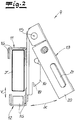
- Fig. 2
- eine Seitenansicht der Längsstrebe mit der daran angebrachten Anschlagvorrichtung sowie dem Anschlagelement in gegenüber dem Haken abgeschwenkten Zustand,
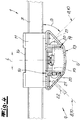
- Fig. 3
- den Gegenstand nach der
Fig. 2 mit dem Anschlagelement in angeschwenktem Zustand an den Haken und zusätzlich angedeutetem Quer-Sicherungsmittel, - Fig. 4
- eine Aufsicht von oben auf den Gegenstand nach der
Fig. 3 teilweise im Schnitt und - Fig. 5
- eine Ansicht auf den Gegenstand nach der
Fig. 3 aus Richtung X.
- Fig. 1
- an overview of a transport vehicle according to the invention in the embodiment as a truck trailer,
- Fig. 2
- 2 shows a side view of the longitudinal strut with the stop device attached to it and the stop element in the state in which it is pivoted away from the hook,
- Fig. 3
- the subject after
Fig. 2 with the stop element in the pivoted state on the hook and additionally indicated cross-securing means, - Fig. 4
- a top view of the item after the
Fig. 3 partly in the cut and - Fig. 5
- a view of the object after the
Fig. 3 from direction X.
In den Figuren ist ein Transportfahrzeug dargestellt, bei dem es sich um einen LKW-Auflieger handelt. In der
Die beiden Bordwände bzw. Längsbordwände definieren in Verbindung mit einer Transportfläche 3 sowie einer nicht dargestellten und optionalen Dachfläche einen hiervon umgrenzten Laderaum 1, 3, 4, 5. Tatsächlich wird der Laderaum zusätzlich zu den beiden Längsbordwänden 1 von einer frontseitigen festen Bordwand 4 und einer rückwärtigen Bordwand 5 in Gestalt von Ladeklappen ergänzend umgrenzt und definiert. Das gilt selbstverständlich nur beispielhaft und nicht einschränkend. Denn ebenso kann es sich bei dem in der
Die beiden Längsbordwände 1 weisen neben der Schiebeplane 2 randseitig der Transportfläche 3 angeordnete Vertikalstreben bzw. Rungen 6 auf. Außerdem sind jeweils zwischen den auf der Transportfläche 3 randseitig aufstehenden Vertikalstreben bzw. Rungen 6 jeweils mehrere Längsstreben 7 bzw. Spriegelbretter angeordnet, die sich überwiegend horizontal erstrecken.In addition to the sliding
Während die Vertikalstreben bzw. Rungen 6 fest mit der Transportfläche 3 bzw. einem Chassis des dargestellten LKW-Aufliegers gekoppelt sind, lassen sich die einzelnen Längsstreben 7 entfernen und ggf. austauschen. Auf diese Weise kann durch Zurückschieben der Schiebeplane 2 entsprechend der Darstellung in der
Die
Tatsächlich handelt es sich bei dem Quer-Sicherungsmittel 8 um ein Sicherungsnetz 8 wie es in der
Die beiden Quer-Sicherungsmittel 8, 10 sind jeweils mit den randseitigen Anschlagvorrichtungen 9 lösbar gekoppelt, die ihrerseits an den Längsstreben 7 lösbar festgelegt sind. Mithilfe der betreffenden Anschlagvorrichtung 9 lässt sich das jeweilige Quer-Sicherungsmittel 8, 10 und folglich auch die Quer-Sicherungsvorrichtung 8, 9; 10, 9 insgesamt positionsvariabel an den sich gegenüberliegenden Längsstreben 7 der Längsbordwände 1 festlegen. Zu diesem Zweck kann die jeweilige Anschlagvorrichtung 9 in praktisch beliebiger Längsposition entlang der in
In jedem Fall lässt sich der Laderaum 1, 3, 4, 5 in seiner Längsrichtung L flexibel segmentieren, denn das betreffende Quer-Sicherungsmittel 8,10 mit den jeweils zugehörigen Anschlagvorrichtungen 9 kann positionsvariabel an den sich gegenüberliegenden Längsstreben 7 des Laderaumes 1, 3, 4, 5 festgelegt werden. Auf diese Weise lassen sich wechselnde Größen des Ladegutes problemlos abbilden und das Ladegut wird dennoch zugleich einwandfrei gesichert.In any case, the
In den
Um die Längsstrebe 7 zwischen den beiden Haken 11, 12 einwandfrei fixieren zu können, sind die beiden Haken 11, 12 relativ zueinander verschiebbar ausgebildet. Außerdem verfügen sie über eine jeweils gleiche bzw. komplementäre U-förmige Gestaltung. Die relative Verschieblichkeit wird im Ausführungsbeispiel und nicht einschränkend so realisiert, dass der kopfseitig der Längsstrebe 7 platzierte Haken 11 zusätzlich mit einem Ausleger 14 ausgerüstet ist, gegenüber dem ein Anschlagelement 13 unter Berücksichtigung einer Drehachse 15 schwenkbar gelagert ist.In order to be able to fix the
Das heißt, der Haken 11 verfügt zunächst einmal über den angeschlossenen Ausleger 14. Der Ausleger 14 ist nun seinerseits mit einer Führung für den demgegenüber verschiebbaren Gegenhaken 12 ausgerüstet. Auf diese Weise kann der Gegenhaken 12 eine in der
Wie bereits erläutert, ist das Anschlagelement 13 gegenüber dem an der Längsstrebe 7 festgelegten Haken 11 an- und abschwenkbar ausgebildet. Dabei findet sich die in diesem Zusammenhang realisierte Drehachse 15 des Anschlagelementes 13 gegenüber dem Haken 11 im Bereich einer oberen Kante der Längsstrebe 7, wie man insbesondere bei einem Vergleich der Darstellung in den
Nach dem Ausführungsbeispiel wird das Anschlagelement 13 im Detail gegenüber dem Ausleger 14 an- und abgeschwenkt, der seinerseits an den Haken 11 angeschlossen ist. Das Anschlagelement 13 ist darüber hinaus gegenüber dem Haken 11 verriegelbar ausgebildet. Zu diesem Zweck verfügt das Anschlagelement 13 über ein gegen Federkraft verschiebbares Rastelement 17, welches man am besten in der
Auf diese Weise lässt sich das Anschlagelement 13 lösbar mit dem Haken 11 bzw. dessen Ausleger 14 und folglich der Längsstrebe 7 verriegeln. Außerdem ist die Auslegung im Ausführungsbeispiel so getroffen, dass das Anschlagelement 13 gegenüber dem an der Längsstrebe 7 festgelegten Haken 11 eine Schwenkbewegung derart vollführt, dass hierbei das Anschlagelement 13 gegenüber dem Haken 11 um einen Winkel α verschwenkt wird, der sich in Richtung auf die Transportfläche 3 des Laderaumes 1, 3, 4, 5 hin öffnet. Nach dem Ausführungsbeispiel werden in diesem Zusammenhang Schwenkwinkel α von ca. 30° bis 40° beobachtet, die sich dadurch einstellen, dass der Ausleger 14 mit entsprechenden und in der
Der Ausleger 14 ist an den Haken 11 laderauminnenseitig zur Lagerung des Anschlagelementes 13 angeschlossen. Außerdem ist der Ausleger 14 im Querschnitt größtenteils U-förmig ausgebildet und zum Laderaum 1, 3, 4, 5 hin bzw. zu dessen Bodenfläche 3 hin geöffnet, wie man insbesondere in der Aufsicht bzw. Schnittdarstellung nach der
Anhand der
Nach dem Ausführungsbeispiel sind sowohl das Anschlagelement 13 als auch die beidseitigen Verlängerungen 20 mit jeweils Aufnahmen 21 für hierin lösbar eingreifende Befestigungselemente 22 des Quer-Sicherungsmittels 8, 10 ausgerüstet. Das erkennt man bei einem Vergleich der
Im Anschluss daran ist das Quer-Sicherungsmittel 8, 10 einsatzbereit und zugleich wunschgemäß gegenüber dem Laderaum 1, 3, 4, 5 orientiert. Dabei eröffnen die jeweils winklig an das Anschlagelement 13 angeschlossenen Verlängerungen 20 mit ihren zugehörigen Ausnehmungen 21 grundsätzlich sogar einen in den
Claims (15)
Applications Claiming Priority (1)
| Application Number | Priority Date | Filing Date | Title |
|---|---|---|---|
| DE202018103744.7U DE202018103744U1 (en) | 2018-06-29 | 2018-06-29 | transport vehicle |
Publications (2)
| Publication Number | Publication Date |
|---|---|
| EP3587181A1 true EP3587181A1 (en) | 2020-01-01 |
| EP3587181B1 EP3587181B1 (en) | 2020-12-16 |
Family
ID=63045726
Family Applications (1)
| Application Number | Title | Priority Date | Filing Date |
|---|---|---|---|
| EP19181358.3A Active EP3587181B1 (en) | 2018-06-29 | 2019-06-19 | Transport vehicle |
Country Status (2)
| Country | Link |
|---|---|
| EP (1) | EP3587181B1 (en) |
| DE (1) | DE202018103744U1 (en) |
Citations (4)
| Publication number | Priority date | Publication date | Assignee | Title |
|---|---|---|---|---|
| US20050141980A1 (en) * | 2003-12-30 | 2005-06-30 | Jps Corporation | Securing device for cargo restraining apparatus |
| DE202007016321U1 (en) * | 2007-09-12 | 2008-02-07 | Bos Gmbh & Co. Kg | hooks |
| US8757946B1 (en) * | 2013-08-29 | 2014-06-24 | Strong Yun Industrial Co., Ltd. | Cargo restraint apparatus |
| DE202016106739U1 (en) * | 2016-12-02 | 2016-12-14 | Westdeutscher Drahtseil-Verkauf Dolezych Gmbh & Co. Kg | Transport vehicle, in particular truck semi-trailer |
-
2018
- 2018-06-29 DE DE202018103744.7U patent/DE202018103744U1/en active Active
-
2019
- 2019-06-19 EP EP19181358.3A patent/EP3587181B1/en active Active
Patent Citations (4)
| Publication number | Priority date | Publication date | Assignee | Title |
|---|---|---|---|---|
| US20050141980A1 (en) * | 2003-12-30 | 2005-06-30 | Jps Corporation | Securing device for cargo restraining apparatus |
| DE202007016321U1 (en) * | 2007-09-12 | 2008-02-07 | Bos Gmbh & Co. Kg | hooks |
| US8757946B1 (en) * | 2013-08-29 | 2014-06-24 | Strong Yun Industrial Co., Ltd. | Cargo restraint apparatus |
| DE202016106739U1 (en) * | 2016-12-02 | 2016-12-14 | Westdeutscher Drahtseil-Verkauf Dolezych Gmbh & Co. Kg | Transport vehicle, in particular truck semi-trailer |
Also Published As
| Publication number | Publication date |
|---|---|
| DE202018103744U1 (en) | 2018-07-13 |
| EP3587181B1 (en) | 2020-12-16 |
Similar Documents
| Publication | Publication Date | Title |
|---|---|---|
| DE2716337C2 (en) | Fixing device for containers on a wall | |
| DE202008016326U1 (en) | Device for securing cargo | |
| WO2018202608A1 (en) | Flow-guide panel | |
| DE202018105613U1 (en) | Device for securing cargo on a loading surface | |
| DE102013004820B4 (en) | Mounting device for storing handrails on a crane | |
| DE4214567A1 (en) | Attaching bicycle carrier frame to rear of vehicle - using pair of spring loaded pins in engagement with bumper bar | |
| EP0446388B1 (en) | Exchangeable container device as well as a fixing device for such a container positioned on a carrying vehicle | |
| EP3587181B1 (en) | Transport vehicle | |
| EP3247589B1 (en) | Transport vehicle | |
| DE102008020629A1 (en) | Safety system for container, particularly for sea transport for protecting large containers, particularly missile transport container, comprises support frame for container, where support frame is fixed in transport position in container | |
| DE2632492A1 (en) | Freight container transport system - with adjacent containers connected by simultaneously actuated hooks which engage lugs | |
| EP2759434A2 (en) | Roller carriage and modular construction system for a roller carriage for a slidable top structure of a truck | |
| EP4212393A1 (en) | Lowerable transport goods holding device, assembly set and method | |
| DE202020105201U1 (en) | Roll container | |
| DE202016106739U1 (en) | Transport vehicle, in particular truck semi-trailer | |
| DE1956392C3 (en) | Collapsible hood, in particular for trucks and trailers | |
| DE3220859C2 (en) | Long goods container | |
| DE102005039355A1 (en) | Arrangement and method for joining swap body to articulated lorry, comprise use of transversal carrying arms and exchangeable end elements | |
| EP3069929B1 (en) | Use of a hole in a transverse beam | |
| DE102015006053B4 (en) | Load securing stanchion system for commercial vehicles | |
| DE102017117986B4 (en) | Transport device for securing goods to be transported on vehicles | |
| DE202007005993U1 (en) | Laminar safety device e.g. for securing loads during transport, has safeguard surface which partly adapts to outline to securing charge and to supply of custom position | |
| DE202010008181U1 (en) | locking device | |
| EP2927896A1 (en) | Fixing system for an information surface on a body of an automobile and method for fixing an information surface to a vehicle structure | |
| DE2218828A1 (en) | BACK PANEL AND COVER WITH DEPENDENT MOVEMENT ON TRUCKS |
Legal Events
| Date | Code | Title | Description |
|---|---|---|---|
| PUAI | Public reference made under article 153(3) epc to a published international application that has entered the european phase |
Free format text: ORIGINAL CODE: 0009012 |
|
| STAA | Information on the status of an ep patent application or granted ep patent |
Free format text: STATUS: THE APPLICATION HAS BEEN PUBLISHED |
|
| AK | Designated contracting states |
Kind code of ref document: A1 Designated state(s): AL AT BE BG CH CY CZ DE DK EE ES FI FR GB GR HR HU IE IS IT LI LT LU LV MC MK MT NL NO PL PT RO RS SE SI SK SM TR |
|
| AX | Request for extension of the european patent |
Extension state: BA ME |
|
| STAA | Information on the status of an ep patent application or granted ep patent |
Free format text: STATUS: REQUEST FOR EXAMINATION WAS MADE |
|
| 17P | Request for examination filed |
Effective date: 20200420 |
|
| RBV | Designated contracting states (corrected) |
Designated state(s): AL AT BE BG CH CY CZ DE DK EE ES FI FR GB GR HR HU IE IS IT LI LT LU LV MC MK MT NL NO PL PT RO RS SE SI SK SM TR |
|
| GRAP | Despatch of communication of intention to grant a patent |
Free format text: ORIGINAL CODE: EPIDOSNIGR1 |
|
| STAA | Information on the status of an ep patent application or granted ep patent |
Free format text: STATUS: GRANT OF PATENT IS INTENDED |
|
| GRAS | Grant fee paid |
Free format text: ORIGINAL CODE: EPIDOSNIGR3 |
|
| INTG | Intention to grant announced |
Effective date: 20200910 |
|
| GRAA | (expected) grant |
Free format text: ORIGINAL CODE: 0009210 |
|
| STAA | Information on the status of an ep patent application or granted ep patent |
Free format text: STATUS: THE PATENT HAS BEEN GRANTED |
|
| AK | Designated contracting states |
Kind code of ref document: B1 Designated state(s): AL AT BE BG CH CY CZ DE DK EE ES FI FR GB GR HR HU IE IS IT LI LT LU LV MC MK MT NL NO PL PT RO RS SE SI SK SM TR |
|
| REG | Reference to a national code |
Ref country code: GB Ref legal event code: FG4D Free format text: NOT ENGLISH |
|
| REG | Reference to a national code |
Ref country code: IE Ref legal event code: FG4D Free format text: LANGUAGE OF EP DOCUMENT: GERMAN |
|
| REG | Reference to a national code |
Ref country code: DE Ref legal event code: R096 Ref document number: 502019000538 Country of ref document: DE |
|
| REG | Reference to a national code |
Ref country code: AT Ref legal event code: REF Ref document number: 1345302 Country of ref document: AT Kind code of ref document: T Effective date: 20210115 |
|
| PG25 | Lapsed in a contracting state [announced via postgrant information from national office to epo] |
Ref country code: FI Free format text: LAPSE BECAUSE OF FAILURE TO SUBMIT A TRANSLATION OF THE DESCRIPTION OR TO PAY THE FEE WITHIN THE PRESCRIBED TIME-LIMIT Effective date: 20201216 Ref country code: RS Free format text: LAPSE BECAUSE OF FAILURE TO SUBMIT A TRANSLATION OF THE DESCRIPTION OR TO PAY THE FEE WITHIN THE PRESCRIBED TIME-LIMIT Effective date: 20201216 Ref country code: NO Free format text: LAPSE BECAUSE OF FAILURE TO SUBMIT A TRANSLATION OF THE DESCRIPTION OR TO PAY THE FEE WITHIN THE PRESCRIBED TIME-LIMIT Effective date: 20210316 Ref country code: GR Free format text: LAPSE BECAUSE OF FAILURE TO SUBMIT A TRANSLATION OF THE DESCRIPTION OR TO PAY THE FEE WITHIN THE PRESCRIBED TIME-LIMIT Effective date: 20210317 |
|
| REG | Reference to a national code |
Ref country code: NL Ref legal event code: MP Effective date: 20201216 |
|
| PG25 | Lapsed in a contracting state [announced via postgrant information from national office to epo] |
Ref country code: BG Free format text: LAPSE BECAUSE OF FAILURE TO SUBMIT A TRANSLATION OF THE DESCRIPTION OR TO PAY THE FEE WITHIN THE PRESCRIBED TIME-LIMIT Effective date: 20210316 Ref country code: SE Free format text: LAPSE BECAUSE OF FAILURE TO SUBMIT A TRANSLATION OF THE DESCRIPTION OR TO PAY THE FEE WITHIN THE PRESCRIBED TIME-LIMIT Effective date: 20201216 Ref country code: LV Free format text: LAPSE BECAUSE OF FAILURE TO SUBMIT A TRANSLATION OF THE DESCRIPTION OR TO PAY THE FEE WITHIN THE PRESCRIBED TIME-LIMIT Effective date: 20201216 |
|
| PG25 | Lapsed in a contracting state [announced via postgrant information from national office to epo] |
Ref country code: HR Free format text: LAPSE BECAUSE OF FAILURE TO SUBMIT A TRANSLATION OF THE DESCRIPTION OR TO PAY THE FEE WITHIN THE PRESCRIBED TIME-LIMIT Effective date: 20201216 Ref country code: NL Free format text: LAPSE BECAUSE OF FAILURE TO SUBMIT A TRANSLATION OF THE DESCRIPTION OR TO PAY THE FEE WITHIN THE PRESCRIBED TIME-LIMIT Effective date: 20201216 |
|
| REG | Reference to a national code |
Ref country code: LT Ref legal event code: MG9D |
|
| PG25 | Lapsed in a contracting state [announced via postgrant information from national office to epo] |
Ref country code: CZ Free format text: LAPSE BECAUSE OF FAILURE TO SUBMIT A TRANSLATION OF THE DESCRIPTION OR TO PAY THE FEE WITHIN THE PRESCRIBED TIME-LIMIT Effective date: 20201216 Ref country code: EE Free format text: LAPSE BECAUSE OF FAILURE TO SUBMIT A TRANSLATION OF THE DESCRIPTION OR TO PAY THE FEE WITHIN THE PRESCRIBED TIME-LIMIT Effective date: 20201216 Ref country code: SM Free format text: LAPSE BECAUSE OF FAILURE TO SUBMIT A TRANSLATION OF THE DESCRIPTION OR TO PAY THE FEE WITHIN THE PRESCRIBED TIME-LIMIT Effective date: 20201216 Ref country code: SK Free format text: LAPSE BECAUSE OF FAILURE TO SUBMIT A TRANSLATION OF THE DESCRIPTION OR TO PAY THE FEE WITHIN THE PRESCRIBED TIME-LIMIT Effective date: 20201216 Ref country code: PT Free format text: LAPSE BECAUSE OF FAILURE TO SUBMIT A TRANSLATION OF THE DESCRIPTION OR TO PAY THE FEE WITHIN THE PRESCRIBED TIME-LIMIT Effective date: 20210416 Ref country code: RO Free format text: LAPSE BECAUSE OF FAILURE TO SUBMIT A TRANSLATION OF THE DESCRIPTION OR TO PAY THE FEE WITHIN THE PRESCRIBED TIME-LIMIT Effective date: 20201216 Ref country code: LT Free format text: LAPSE BECAUSE OF FAILURE TO SUBMIT A TRANSLATION OF THE DESCRIPTION OR TO PAY THE FEE WITHIN THE PRESCRIBED TIME-LIMIT Effective date: 20201216 |
|
| PG25 | Lapsed in a contracting state [announced via postgrant information from national office to epo] |
Ref country code: PL Free format text: LAPSE BECAUSE OF FAILURE TO SUBMIT A TRANSLATION OF THE DESCRIPTION OR TO PAY THE FEE WITHIN THE PRESCRIBED TIME-LIMIT Effective date: 20201216 |
|
| REG | Reference to a national code |
Ref country code: DE Ref legal event code: R097 Ref document number: 502019000538 Country of ref document: DE |
|
| PG25 | Lapsed in a contracting state [announced via postgrant information from national office to epo] |
Ref country code: IS Free format text: LAPSE BECAUSE OF FAILURE TO SUBMIT A TRANSLATION OF THE DESCRIPTION OR TO PAY THE FEE WITHIN THE PRESCRIBED TIME-LIMIT Effective date: 20210416 |
|
| PLBE | No opposition filed within time limit |
Free format text: ORIGINAL CODE: 0009261 |
|
| STAA | Information on the status of an ep patent application or granted ep patent |
Free format text: STATUS: NO OPPOSITION FILED WITHIN TIME LIMIT |
|
| PG25 | Lapsed in a contracting state [announced via postgrant information from national office to epo] |
Ref country code: IT Free format text: LAPSE BECAUSE OF FAILURE TO SUBMIT A TRANSLATION OF THE DESCRIPTION OR TO PAY THE FEE WITHIN THE PRESCRIBED TIME-LIMIT Effective date: 20201216 Ref country code: AL Free format text: LAPSE BECAUSE OF FAILURE TO SUBMIT A TRANSLATION OF THE DESCRIPTION OR TO PAY THE FEE WITHIN THE PRESCRIBED TIME-LIMIT Effective date: 20201216 |
|
| 26N | No opposition filed |
Effective date: 20210917 |
|
| PG25 | Lapsed in a contracting state [announced via postgrant information from national office to epo] |
Ref country code: DK Free format text: LAPSE BECAUSE OF FAILURE TO SUBMIT A TRANSLATION OF THE DESCRIPTION OR TO PAY THE FEE WITHIN THE PRESCRIBED TIME-LIMIT Effective date: 20201216 |
|
| PG25 | Lapsed in a contracting state [announced via postgrant information from national office to epo] |
Ref country code: MC Free format text: LAPSE BECAUSE OF FAILURE TO SUBMIT A TRANSLATION OF THE DESCRIPTION OR TO PAY THE FEE WITHIN THE PRESCRIBED TIME-LIMIT Effective date: 20201216 Ref country code: ES Free format text: LAPSE BECAUSE OF FAILURE TO SUBMIT A TRANSLATION OF THE DESCRIPTION OR TO PAY THE FEE WITHIN THE PRESCRIBED TIME-LIMIT Effective date: 20201216 |
|
| PG25 | Lapsed in a contracting state [announced via postgrant information from national office to epo] |
Ref country code: SI Free format text: LAPSE BECAUSE OF FAILURE TO SUBMIT A TRANSLATION OF THE DESCRIPTION OR TO PAY THE FEE WITHIN THE PRESCRIBED TIME-LIMIT Effective date: 20201216 |
|
| REG | Reference to a national code |
Ref country code: BE Ref legal event code: MM Effective date: 20210630 |
|
| PG25 | Lapsed in a contracting state [announced via postgrant information from national office to epo] |
Ref country code: LU Free format text: LAPSE BECAUSE OF NON-PAYMENT OF DUE FEES Effective date: 20210619 |
|
| PG25 | Lapsed in a contracting state [announced via postgrant information from national office to epo] |
Ref country code: IE Free format text: LAPSE BECAUSE OF NON-PAYMENT OF DUE FEES Effective date: 20210619 |
|
| PG25 | Lapsed in a contracting state [announced via postgrant information from national office to epo] |
Ref country code: IS Free format text: LAPSE BECAUSE OF FAILURE TO SUBMIT A TRANSLATION OF THE DESCRIPTION OR TO PAY THE FEE WITHIN THE PRESCRIBED TIME-LIMIT Effective date: 20210416 Ref country code: FR Free format text: LAPSE BECAUSE OF NON-PAYMENT OF DUE FEES Effective date: 20210630 |
|
| PG25 | Lapsed in a contracting state [announced via postgrant information from national office to epo] |
Ref country code: BE Free format text: LAPSE BECAUSE OF NON-PAYMENT OF DUE FEES Effective date: 20210630 |
|
| REG | Reference to a national code |
Ref country code: CH Ref legal event code: PL |
|
| PG25 | Lapsed in a contracting state [announced via postgrant information from national office to epo] |
Ref country code: LI Free format text: LAPSE BECAUSE OF NON-PAYMENT OF DUE FEES Effective date: 20220630 Ref country code: CH Free format text: LAPSE BECAUSE OF NON-PAYMENT OF DUE FEES Effective date: 20220630 |
|
| PG25 | Lapsed in a contracting state [announced via postgrant information from national office to epo] |
Ref country code: CY Free format text: LAPSE BECAUSE OF FAILURE TO SUBMIT A TRANSLATION OF THE DESCRIPTION OR TO PAY THE FEE WITHIN THE PRESCRIBED TIME-LIMIT Effective date: 20201216 |
|
| PG25 | Lapsed in a contracting state [announced via postgrant information from national office to epo] |
Ref country code: HU Free format text: LAPSE BECAUSE OF FAILURE TO SUBMIT A TRANSLATION OF THE DESCRIPTION OR TO PAY THE FEE WITHIN THE PRESCRIBED TIME-LIMIT; INVALID AB INITIO Effective date: 20190619 |
|
| GBPC | Gb: european patent ceased through non-payment of renewal fee |
Effective date: 20230619 |
|
| PG25 | Lapsed in a contracting state [announced via postgrant information from national office to epo] |
Ref country code: MK Free format text: LAPSE BECAUSE OF FAILURE TO SUBMIT A TRANSLATION OF THE DESCRIPTION OR TO PAY THE FEE WITHIN THE PRESCRIBED TIME-LIMIT Effective date: 20201216 Ref country code: GB Free format text: LAPSE BECAUSE OF NON-PAYMENT OF DUE FEES Effective date: 20230619 |
|
| PG25 | Lapsed in a contracting state [announced via postgrant information from national office to epo] |
Ref country code: TR Free format text: LAPSE BECAUSE OF FAILURE TO SUBMIT A TRANSLATION OF THE DESCRIPTION OR TO PAY THE FEE WITHIN THE PRESCRIBED TIME-LIMIT Effective date: 20201216 |
|
| PGFP | Annual fee paid to national office [announced via postgrant information from national office to epo] |
Ref country code: DE Payment date: 20240531 Year of fee payment: 6 |
|
| PG25 | Lapsed in a contracting state [announced via postgrant information from national office to epo] |
Ref country code: MT Free format text: LAPSE BECAUSE OF FAILURE TO SUBMIT A TRANSLATION OF THE DESCRIPTION OR TO PAY THE FEE WITHIN THE PRESCRIBED TIME-LIMIT Effective date: 20201216 |