EP3587017A1 - Verfahren zum herstellen einer laufscheibe für eine strömungsmaschine - Google Patents
Verfahren zum herstellen einer laufscheibe für eine strömungsmaschine Download PDFInfo
- Publication number
- EP3587017A1 EP3587017A1 EP19182952.2A EP19182952A EP3587017A1 EP 3587017 A1 EP3587017 A1 EP 3587017A1 EP 19182952 A EP19182952 A EP 19182952A EP 3587017 A1 EP3587017 A1 EP 3587017A1
- Authority
- EP
- European Patent Office
- Prior art keywords
- profile
- grooves
- profile groove
- profile grooves
- wall surfaces
- Prior art date
- Legal status (The legal status is an assumption and is not a legal conclusion. Google has not performed a legal analysis and makes no representation as to the accuracy of the status listed.)
- Granted
Links
Images

Classifications
-
- B—PERFORMING OPERATIONS; TRANSPORTING
- B23—MACHINE TOOLS; METAL-WORKING NOT OTHERWISE PROVIDED FOR
- B23H—WORKING OF METAL BY THE ACTION OF A HIGH CONCENTRATION OF ELECTRIC CURRENT ON A WORKPIECE USING AN ELECTRODE WHICH TAKES THE PLACE OF A TOOL; SUCH WORKING COMBINED WITH OTHER FORMS OF WORKING OF METAL
- B23H9/00—Machining specially adapted for treating particular metal objects or for obtaining special effects or results on metal objects
- B23H9/10—Working turbine blades or nozzles
-
- B—PERFORMING OPERATIONS; TRANSPORTING
- B23—MACHINE TOOLS; METAL-WORKING NOT OTHERWISE PROVIDED FOR
- B23P—METAL-WORKING NOT OTHERWISE PROVIDED FOR; COMBINED OPERATIONS; UNIVERSAL MACHINE TOOLS
- B23P15/00—Making specific metal objects by operations not covered by a single other subclass or a group in this subclass
- B23P15/02—Making specific metal objects by operations not covered by a single other subclass or a group in this subclass turbine or like blades from one piece
-
- B—PERFORMING OPERATIONS; TRANSPORTING
- B23—MACHINE TOOLS; METAL-WORKING NOT OTHERWISE PROVIDED FOR
- B23D—PLANING; SLOTTING; SHEARING; BROACHING; SAWING; FILING; SCRAPING; LIKE OPERATIONS FOR WORKING METAL BY REMOVING MATERIAL, NOT OTHERWISE PROVIDED FOR
- B23D43/00—Broaching tools
- B23D43/02—Broaching tools for cutting by rectilinear movement
-
- F—MECHANICAL ENGINEERING; LIGHTING; HEATING; WEAPONS; BLASTING
- F01—MACHINES OR ENGINES IN GENERAL; ENGINE PLANTS IN GENERAL; STEAM ENGINES
- F01D—NON-POSITIVE DISPLACEMENT MACHINES OR ENGINES, e.g. STEAM TURBINES
- F01D5/00—Blades; Blade-carrying members; Heating, heat-insulating, cooling or antivibration means on the blades or the members
- F01D5/30—Fixing blades to rotors; Blade roots ; Blade spacers
-
- B—PERFORMING OPERATIONS; TRANSPORTING
- B23—MACHINE TOOLS; METAL-WORKING NOT OTHERWISE PROVIDED FOR
- B23C—MILLING
- B23C2220/00—Details of milling processes
- B23C2220/36—Production of grooves
- B23C2220/366—Turbine blade grooves
-
- B—PERFORMING OPERATIONS; TRANSPORTING
- B23—MACHINE TOOLS; METAL-WORKING NOT OTHERWISE PROVIDED FOR
- B23D—PLANING; SLOTTING; SHEARING; BROACHING; SAWING; FILING; SCRAPING; LIKE OPERATIONS FOR WORKING METAL BY REMOVING MATERIAL, NOT OTHERWISE PROVIDED FOR
- B23D43/00—Broaching tools
- B23D43/02—Broaching tools for cutting by rectilinear movement
- B23D2043/025—Broaching tools for cutting by rectilinear movement for producing grooves in turbines, e.g. for the insertion of blades
-
- B—PERFORMING OPERATIONS; TRANSPORTING
- B23—MACHINE TOOLS; METAL-WORKING NOT OTHERWISE PROVIDED FOR
- B23P—METAL-WORKING NOT OTHERWISE PROVIDED FOR; COMBINED OPERATIONS; UNIVERSAL MACHINE TOOLS
- B23P15/00—Making specific metal objects by operations not covered by a single other subclass or a group in this subclass
- B23P15/006—Making specific metal objects by operations not covered by a single other subclass or a group in this subclass turbine wheels
-
- F—MECHANICAL ENGINEERING; LIGHTING; HEATING; WEAPONS; BLASTING
- F05—INDEXING SCHEMES RELATING TO ENGINES OR PUMPS IN VARIOUS SUBCLASSES OF CLASSES F01-F04
- F05D—INDEXING SCHEME FOR ASPECTS RELATING TO NON-POSITIVE-DISPLACEMENT MACHINES OR ENGINES, GAS-TURBINES OR JET-PROPULSION PLANTS
- F05D2230/00—Manufacture
- F05D2230/10—Manufacture by removing material
-
- F—MECHANICAL ENGINEERING; LIGHTING; HEATING; WEAPONS; BLASTING
- F05—INDEXING SCHEMES RELATING TO ENGINES OR PUMPS IN VARIOUS SUBCLASSES OF CLASSES F01-F04
- F05D—INDEXING SCHEME FOR ASPECTS RELATING TO NON-POSITIVE-DISPLACEMENT MACHINES OR ENGINES, GAS-TURBINES OR JET-PROPULSION PLANTS
- F05D2240/00—Components
- F05D2240/20—Rotors
- F05D2240/24—Rotors for turbines
Definitions
- the present invention relates to a method for producing a rotor for a turbomachine.
- the turbomachine can, for example, be a jet engine, e.g. B. a turbofan engine.
- the fluid machine is functionally divided into a compressor, combustion chamber and turbine.
- the air drawn in is compressed by the compressor and burned in the downstream combustion chamber with added kerosene.
- the resulting hot gas a mixture of combustion gas and air, flows through the downstream turbine and is expanded in the process.
- the turbine generally has several stages, each of which is made up of a guide vane ring and a downstream rotor blade wheel. In the individual stages, energy is partially extracted from the flowing hot gas and converted into rotation of the rotor blades (this can then be used, for example, at least partially to drive the compressor).
- the rotor blades are each constructed from a rotor on which the rotor blades are mounted in a form-fitting manner in succession all around.
- the running disk is provided with a blade root receptacle in different circumferential positions, namely an axially extending profile groove is introduced in each case.
- a blade root is inserted into each profile groove, the outer wall surface of which then forms a positive connection with an inner wall surface of the running disk delimiting the profile groove. Due to the profiling of the groove, the rotor blade is held in a radially positive manner.
- the present invention is based on the technical problem of specifying a particularly advantageous method for producing a running disk with profile grooves.
- the profile grooves are introduced in groups one after the other, ie first profile grooves in first circumferential positions and then second profile grooves in second circumferential positions.
- at least one second circumferential position is always arranged between two first circumferential positions, so that when a respective first profile groove is introduced, the circumferentially next adjacent profile grooves initially remain.
- the second profile grooves are introduced, the circumferentially next adjacent first profile grooves are then supported on their inner wall surfaces.
- This procedure is advantageous insofar as there is sufficient disc material when inserting the first profile grooves in the circulation positions "in between” so that, for example, there is none or none relevant in the case of metal removal and the associated force when the first profile grooves are introduced Deformation occurs (the web that remains between two profile grooves is critical in this respect).
- the removal of material can be economically interesting, but it can represent a mechanical load.
- the disk is already weakened in the first circumferential positions, which is why the first profile groove or grooves are supported here.
- the grooves are each supported on their inner wall surfaces, with the result that a deformation or an offset of the inner wall surfaces towards one another (into the profile groove) is counteracted.
- the web remaining between two profile grooves can be regarded as a bending beam that is suspended radially on the inside and has a free end on the radially outside. Due to the procedure according to the invention, that is to say the intermediate positions which remain free, the bending beams remaining when the first profile grooves are introduced are sufficiently thick and thus stable with respect to the preferred material removal. When the second profile grooves are introduced, the remaining bending beams are then significantly thinner, but the support on the inner wall surfaces of the first profile grooves nevertheless creates stability.
- the first profile grooves can also be removed without cutting, for example, erosively; cutting is preferred, see below.
- the profile grooves can be introduced in different orders or intervals.
- the first profile grooves it is possible, for example, to switch sequentially to the first circumferential position next to the circumference, but this is only one possibility.
- the first profile grooves can be introduced in any order or even simultaneously, with the second circulation positions remaining in between there is sufficient stability. This applies analogously to the second profile grooves, due to the support on the first circumferential positions.
- an insert is placed in the profile groove to be supported, which is then removed again.
- the insert lies against the inner wall surface, preferably with an axially complementary contour, at least in sections, and supports the profile groove. After removal, the insert can be used to support a further profile groove, for example the same disc in a sequential processing or a running disc produced afterwards.
- the insert has a tensioning device with which it can be widened in the circumferential direction after insertion and thus expanded.
- a wedge mechanism can be provided, for example, as a tensioning device.
- the insert is spread open by actuating the tensioning device, it is reversibly insertable and removable (after loosening the tensioning device), at the same time high support forces are possible.
- a backfill material is introduced into the profile groove to be supported. This is when the insert is in an informal or neutral state, in the profile groove it changes into a dimensionally stable state. Then the backfill material is then removed from the profile groove again, which depending on the backfill material can take place, for example, chemically, thermally or also erosively or mechanically (if the dimensionally stable backfill material is "softer" than the disc material, mechanical removal can be less stressful than the exciting one Introduce a profile groove).
- the backfill material is introduced in an at least viscous, flowable form, for example it can be poured in or even coated.
- a plastic material can preferably be used, in particular a hard plastic, for example polycarbonate.
- a metallic filling material is also possible, e.g. B. aluminum.
- the geometry of the profile grooves can also determine whether it can be supported with a plastic material that is easier to release or whether a metallic backfill material is required.
- the filler material introduced in a formless / shape-neutral manner does not fill the entire profile groove for itself, but instead a molded body (in a dimensionally stable state) is introduced into the profile groove. To a certain extent, this is fastened, for example glued, into the profile groove by joining. Then only the backfill material can be released and the molded body removed or the backfill material including the molded article can also be triggered.
- exactly one second profile groove is always circumferentially between two first profile grooves. When they are introduced, both circumferentially next adjacent first profile grooves are supported. If, on the other hand, there is more than one circumferential position between two first profile grooves, it may also be sufficient when inserting the second profile groove if only one circumferentially next adjacent first profile groove is supported because enough disc material has remained in the opposite direction of rotation.
- first and second profile grooves As long as intermediate positions remain, a certain nesting is generally also conceivable when introducing the first and second profile grooves. For example, two circumferentially next adjacent first profile grooves can be introduced and supported, and the second profile groove can then be introduced in between before the introduction of further first profile grooves. In a preferred embodiment, however, all the first profile grooves and then all the second profile grooves are introduced first.
- all of the first profile grooves are supported when a respective second profile groove is introduced.
- the support does not change from groove to groove (which is generally possible), but a filler material or insert is placed in all the first profile grooves, then the second profile grooves are introduced.
- the first profile grooves are made by cutting material, that is, with a geometrically determined or generally also undetermined cutting edge.
- cutting material that is, with a geometrically determined or generally also undetermined cutting edge.
- broaching is preferred, for example with a broaching tool made of high-speed steel ( HSS).
- HSS high-speed steel
- broaching can be economically interesting compared to other cutting processes, this advantage only being fully realized in the course of the procedure according to the invention.
- the disk material is when the first profile grooves are made due to the initially remaining intermediate positions less susceptible to deformation, larger forces are not harmful when removing material. Since the forces typically increase with tool wear, the service life can be extended with the approach according to the invention.
- the second profile grooves are made by cutting material, in particular by broaching.
- the advantages just described for the first profile grooves apply analogously. Due to the support, a higher force input is possible when inserting the second profile grooves, so the tools can be used longer or manual rework is unnecessary.
- the second profile grooves are introduced in a non-cutting process (ie not cutting), for example erosively, for example by spark or wire EDM.
- a non-cutting process ie not cutting
- the advantage of an erosive process can be a lower force input (compared to cutting).
- This object is therefore also considered an invention regardless of the main claim supporting the first profile grooves and should be disclosed accordingly.
- the disclosure therefore also relates in particular to a method in which the first profile grooves are first introduced without cutting or preferably cutting and then the second profile grooves are introduced in an erosive manner, no support for the first profile grooves being necessary (it is possible but not mandatory).
- a preferred embodiment relates to the geometry of the profile grooves or webs remaining therebetween, specifically the ratio of radial groove depth T and web width B taken in the circumferential direction.
- This ratio is preferably at least 2.5, with at least 3 or 3.5 further and particularly preferred are. Possible upper limits can be, for example, a maximum of 8 or 7.
- a correspondingly In the case of a geared fan engine, for example, a high T / B ratio can be located in the high-speed low-pressure turbine. Without the procedure according to the invention, profile grooves with a T / B ratio greater than 2.5 or 3.5 can no longer be produced economically (tool life and manual rework, see above).
- the running disks also tend to become smaller (from generation to generation), with the number of blades generally increasing (in order to achieve a comparable or improved efficiency).
- the components are becoming more delicate, so the web widths decrease, so the T / B ratio increases.
- the required tolerances are also narrowing, which can nevertheless be achieved with the present approach with at least limited or entirely without manual post-processing.
- the radial depth T is taken up to the profile base of the respective profile groove, starting from the circumference of the disk.
- the width B is taken at the level of a constriction of the web, that is to say radially within the supporting flanks of the two adjacent grooves.
- the profile grooves can be provided as so-called dovetail grooves, so the inner wall surfaces can each form exactly one supporting flank.
- fir tree-shaped profile grooves can also be preferred, with at least two supporting flanks being arranged on each inner wall surface.
- the invention also relates to a method for producing a module of a turbomachine, in particular an aircraft engine.
- the module can preferably be a turbine module, in particular a low-pressure turbine module. It has a paddle wheel with a running disk discussed here, in whose profile grooves moving blades are inserted. Of course, the module can also have several such paddle wheels.
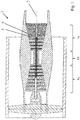
- FIG. 1 shows a turbomachine 1, specifically a turbofan engine, in an axial section.
- the flow machine 1 is functionally divided into a compressor 1a, a combustion chamber 1b and a turbine 1c. Both the compressor 1a and the turbine 1c are each made up of several stages. Each of the stages is composed of a guide vane ring and a subsequent rotor blade wheel. For the sake of clarity, only one of the stages of the guide vane ring 3 and the associated rotor blade wheel 4 is referenced with reference numerals for the turbine 1c.
- the air sucked in is compressed in the compressor 1a and is then burned in the downstream combustion chamber 1b with added kerosene.
- the hot gas flows through the hot gas channel and thereby drives the impeller 4 or the impeller wheels, which rotate about the axis of rotation 2.
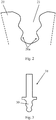
- FIG 2 shows a detailed view of part of the impeller 4, namely a disc 20.
- a profile groove 21 is made, in which a blade root 30 a blade 31 is used, compare Figure 3 for illustration. Because of the profiling of the profile groove 21, that is to say because of the contour of the inner wall surfaces 20a, the rotor blade 31 is held in a radially positive manner therein.
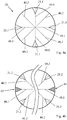
- the production of the running disk 20 is based on the Figures 4a-c explained.
- the first profile grooves 21.1 are introduced into the disk 20 in the first circulating positions 40.1.
- a second circulating position 40.2 is arranged between each of the first circulating positions 40.1, so intermediate positions remain free for the time being. Accordingly, there is still sufficient material all around, so the first profile grooves 21.1 can be made by broaching.
Landscapes
- Engineering & Computer Science (AREA)
- Mechanical Engineering (AREA)
- Physics & Mathematics (AREA)
- Thermal Sciences (AREA)
- General Engineering & Computer Science (AREA)
- Structures Of Non-Positive Displacement Pumps (AREA)
Abstract
Description
- Die vorliegende Erfindung betrifft ein Verfahren zum Herstellen einer Laufscheibe für eine Strömungsmaschine.
- Bei der Strömungsmaschine kann es sich bspw. um ein Strahltriebwerk handeln, z. B. um ein Mantelstromtriebwerk. Funktional gliedert sich die Strömungsmaschine in Verdichter, Brennkammer und Turbine. Etwa im Falle des Strahltriebwerks wird angesaugte Luft vom Verdichter komprimiert und in der nachgelagerten Brennkammer mit hinzugemischtem Kerosin verbrannt. Das entstehende Heißgas, eine Mischung aus Verbrennungsgas und Luft, durchströmt die nachgelagerte Turbine und wird dabei expandiert. Die Turbine weist in der Regel mehrere Stufen auf, die jeweils aus einem Leitschaufelkranz und einem nachgelagerten Laufschaufelrad aufgebaut sind. In den einzelnen Stufen wird dem strömenden Heißgas jeweils anteilig Energie entzogen und in eine Rotation der Laufschaufelräder umgesetzt (diese kann dann z. B. zumindest anteilig zum Antreiben des Verdichters genutzt werden).
- Die Laufschaufelräder sind dabei jeweils aus einer Laufscheibe aufgebaut, an der die Laufschaufeln umlaufend aufeinanderfolgend jeweils formschlüssig montiert sind. Dazu ist die Laufscheibe auf unterschiedlichen Umlaufpositionen jeweils mit einer Schaufelfußaufnahme versehen, ist nämlich jeweils eine sich axial erstreckende Profilnut eingebracht. In jede Profilnut wird ein Schaufelfuß eingesetzt, dessen Außenwandfläche dann einen Formschluss mit einer die Profilnut begrenzenden Innenwandfläche der Laufscheibe bildet. Aufgrund der Profilierung der Nut ist die Laufschaufel radial formschlüssig gehalten.
- Der vorliegenden Erfindung liegt das technische Problem zugrunde, ein besonders vorteilhaftes Verfahren zum Herstellen einer Laufscheibe mit Profilnuten anzugeben.
- Dies wird erfindungsgemäß mit dem Verfahren gemäß Anspruch 1 gelöst. Die Profilnuten werden dabei gruppenweise nacheinander eingebracht, also zunächst erste Profilnuten auf ersten Umlaufpositionen und anschließend zweite Profilnuten auf zweiten Umlaufpositionen. Hierbei ist zwischen zwei ersten Umlaufpositionen jeweils immer mindestens eine zweite Umlaufposition angeordnet, bleiben beim Einbringen einer jeweiligen ersten Profilnut also jedenfalls die umlaufend nächstbenachbarten Profilnuten zunächst stehen. Beim Einbringen der zweiten Profilnuten wird bzw. werden die umlaufend nächstbenachbarten ersten Profilnuten dann an ihren Innenwandflächen abgestützt.
- Diese Vorgehensweise ist insoweit vorteilhaft, als beim Einbringen der ersten Profilnuten auf den Umlaufpositionen "dazwischen" noch hinreichend Scheibenmaterial vorhanden ist, sodass es bspw. auch im Falle eines spanenden Materialabtrags und der damit einhergehenden Krafteinwirkung beim Einbringen der ersten Profilnuten zu keiner bzw. keiner maßgeblichen Verformung kommt (kritisch ist insoweit der Steg, der zwischen zwei Profilnuten verbleibt). Der spanende Materialabtrag kann wirtschaftlich interessant sein, aber eine mechanische Belastung darstellen. Beim Einbringen der zweiten Profilnuten ist die Scheibe auf den ersten Umlaufpositionen bereits geschwächt, weswegen hierbei die erste Profilnut bzw. -nuten abgestützt werden. Die Nuten werden jeweils an ihren Innenwandflächen abgestützt, womit einer Verformung bzw. einem Versatz der Innenwandflächen zueinander hin (in die Profilnut hinein) entgegengewirkt wird.
- Zur Illustration kann man den zwischen zwei Profilnuten verbleibenden Steg als Biegebalken betrachten, der radial innen aufgehängt ist und radial außen ein freies Ende hat. Aufgrund der erfindungsgemäßen Vorgehensweise, also der freibleibenden Zwischenpositionen, sind die beim Einbringen der ersten Profilnuten verbleibenden Biegebalken hinreichend dick und damit stabil bzgl. des bevorzugten spanenden Materialabtrags. Beim Einbringen der zweiten Profilnuten sind die verbleibenden Biegebalken dann deutlich dünner, schafft jedoch die Abstützung an den Innenwandflächen der ersten Profilnuten gleichwohl eine Stabilität. Prinzipiell können die ersten Profilnuten auch spanfrei abtragend, bspw. erosiv eingebracht werden, bevorzugt ist ein Spanen, siehe unten.
- Bevorzugte Ausgestaltungen finden sich in den abhängigen Ansprüchen und der gesamten Offenbarung, wobei die Darstellung stets sowohl die Herstellung einer Laufscheibe als auch eines entsprechenden Laufrads bzw. Moduls der Strömungsmaschine betrifft. Angaben wie "axial" und "radial" bzw. "umlaufend" und die dazugehörigen Richtungen betreffen die Drehachse der Laufscheibe, um welche diese im Betrieb rotiert (und die in der Regel mit der Längsachse der Strömungsmaschine zusammenfällt).
- Innerhalb einer jeweiligen Gruppe können die Profilnuten in unterschiedlicher Reihenfolge bzw. Taktung eingebracht werden. Im Falle der ersten Profilnuten kann bspw. jeweils sequenziell zur umlaufend nächstbenachbarten ersten Umlaufposition gewechselt werden, was aber nur eine Möglichkeit darstellt. Im Prinzip können die ersten Profilnuten in beliebiger Reihenfolge oder sogar auch simultan eingebracht werden, mit den dazwischen verbleibenden zweiten Umlaufpositionen ist hinreichend Stabilität gegeben. Dies gilt analog für die zweiten Profilnuten, aufgrund der Abstützung auf den ersten Umlaufpositionen.
- Im Folgenden werden zunächst verschiedene bevorzugte Möglichkeiten zur Abstützung der ersten Profilnuten diskutiert.
- Bei einer bevorzugten Ausführungsform wird ein Einsatz in die abzustützende Profilnut gesetzt, der dann anschließend wieder herausgenommen wird. Der Einsatz liegt an der Innenwandfläche an, vorzugsweise mit einer axial gesehen zumindest abschnittsweise komplementären Kontur, und stützt die Profilnut ab. Nach dem Herausnehmen kann der Einsatz zum Abstützen einer weiteren Profilnut genutzt werden, bspw. derselben Scheibe bei einer sequenziellen Bearbeitung oder einer im Anschluss hergestellten Laufscheibe.
- In bevorzugter Ausgestaltung weist der Einsatz eine Spanneinrichtung auf, mit welcher er nach dem Einsetzen in Umlaufrichtung geweitet und damit verspreizt werden kann. Als Spannvorrichtung kann bspw. ein Keilmechanismus vorgesehen sein, z. B. durch einen Spann- bzw. Schraubbolzen angetrieben. Beim Spannen kann bspw. ein Keil bzw. Doppelkeil axial oder auch radial versetzt werden und dabei einen Klemmkörper des Einsatzes mit entsprechenden Schrägflanken in Umlaufrichtung nach außen drücken. Der Einsatz wird durch Betätigen der Spanneinrichtung aufgespreizt, er ist reversibel einsetz- und herausnehmbar (nach Lösen der Spanneinrichtung), zugleich sind hohe Abstützkräfte möglich.
- Bei einer anderen bevorzugten Ausführungsform wird in die abzustützende Profilnut ein Verfüllmaterial eingebracht. Dieses ist beim Einbringen in einem formlosen bzw. -neutralen Zustand, in der Profilnut geht es in einen formfesten Zustand über. Anschließend wird das Verfüllmaterial dann wieder aus der Profilnut entfernt, was je nach Verfüllmaterial bspw. chemisch, thermisch oder auch erosiv bzw. mechanisch erfolgen kann (ist das formfeste Verfüllmaterial "weicher" als das Scheibenmaterial, kann eine mechanische Entfernung eine geringere Belastung als das spannende Einbringen einer Profilnut darstellen).
- In bevorzugter Ausgestaltung wird das Verfüllmaterial in einer zumindest viskos fließfähigen Form eingebracht, es kann bspw. eingegossen bzw. auch eingestrichen werden. Bevorzugt kann ein Kunststoffmaterial Anwendung finden, insbesondere ein Hartkunststoff, bspw. Polycarbonat. Alternativ ist jedoch auch ein metallisches Verfüllmaterial möglich, z. B. Aluminium. Im Einzelnen kann auch von der Geometrie der Profilnuten (T/B, siehe unten) abhängen, ob mit einem Kunststoffmaterial abgestützt werden kann, das leichter auszulösen ist, oder ein metallisches Verfüllmaterial erforderlich ist.
- Bei einer bevorzugten Ausführungsform füllt das formlos/formneutral eingebrachte Verfüllmaterial nicht für sich die gesamte Profilnut aus, sondern wird zusätzlich ein Formkörper (in formfesten Zustand) in die Profilnut eingebracht. Dieser wird also gewissermaßen durch Fügen in der Profilnut befestigt, bspw. eingeklebt. Anschließend kann dann nur das Verfüllmaterial ausgelöst und der Formkörper herausgenommen werden, oder es kann auch das Verfüllmaterial samt Formkörper ausgelöst werden.
- In bevorzugter Ausgestaltung liegt umlaufend zwischen zwei ersten Profilnuten immer genau eine zweite Profilnut. Bei deren Einbringen werden beide umlaufend nächstbenachbarten ersten Profilnuten abgestützt. Liegt hingegen zwischen zwei ersten Profilnuten mehr als eine Umlaufposition, kann es beim Einbringen der zweiten Profilnut auch ausreichend sein, wenn nur eine umlaufend nächstbenachbarte erste Profilnut abgestützt wird, weil in der entgegengesetzten Umlaufrichtung noch genug Scheibenmaterial stehen geblieben ist.
- Solange Zwischenpositionen verbleiben, ist im Allgemeinen sogar auch eine gewisse Verschachtelung beim Einbringen der ersten und zweiten Profilnuten denkbar. Es können bspw. zwei umlaufend nächstbenachbarte erste Profilnuten eingebracht und abgestützt werden, und kann dann die zweite Profilnut dazwischen noch vor dem Einbringen weiterer erster Profilnuten eingebracht werden. In bevorzugter Ausgestaltung werden jedoch zunächst alle ersten Profilnuten und anschließend alle zweiten Profilnuten eingebracht.
- Bei einer bevorzugten Ausführungsform sind alle ersten Profilnuten abgestützt, wenn eine jeweilige zweite Profilnut eingebracht wird. Mit dem Abstützen wird dann also nicht von Nut zu Nut gewechselt (was im Allgemeinen möglich ist), sondern es wird in sämtlichen ersten Profilnuten ein Verfüllmaterial oder Einsatz platziert, dann werden die zweiten Profilnuten eingebracht.
- Bei einer bevorzugten Ausführungsform werden die ersten Profilnuten durch spanenden Materialabtrag eingebracht, also mit einer geometrisch bestimmten oder im Allgemeinen auch unbestimmten Schneide. Es ist bspw. auch ein Fräsen denkbar, bevorzugt ist ein Räumen, bspw. mit einem Räumwerkzeug aus einem Schnellarbeitsstahl (High Speed Steel, HSS). Das Räumen kann an sich gegenüber anderen spanenden Verfahren wirtschaftlich interessant sein, wobei dieser Vorteil erst im Zuge der erfindungsgemäßen Vorgehensweise vollends zu tragen kommt. Wie eingangs diskutiert, ist das Scheibenmaterial beim Einbringen der ersten Profilnuten aufgrund der zunächst verbleibenden Zwischenpositionen weniger verformungsanfällig, sind also beim Materialabtragen größere Kräfte unschädlich. Da die Kräfte typischerweise mit dem Werkzeugverschleiß zunehmen, lassen sich mit dem erfindungsgemäßen Ansatz die Standzeiten verlängern. Wären die beim Spanen zulässigen Kräfte aufgrund "dünner" Stege hingegen deutlich limitiert, würde dies einen häufigen Werkzeugwechsel mit entsprechenden ökonomischen Nachteilen bedeuten. Die geforderten Toleranzen ließen sich mitunter auch gar nicht mehr erreichen (auch ein kraftoptimiertes Räumwerkzeug ist niemals völlig kraftfrei), was aufwändiges manuelles Nachbearbeiten erforderlich machen würde.
- In bevorzugter Ausgestaltung werden die zweiten Profilnuten durch spanenden Materialabtrag, insbesondere durch Räumen eingebracht. Die eben für die ersten Profilnuten geschilderten Vorteile gelten analog. Aufgrund der Abstützung ist beim Einbringen der zweiten Profilnuten ein höherer Krafteintrag möglich, lassen sich also die Werkzeuge länger nutzen bzw. wird eine manuelle Nachbearbeitung überflüssig.
- Bei einer alternativ bevorzugten Ausführungsform werden die zweiten Profilnuten in einem spanfrei abtragenden Verfahren (also nicht spanend) eingebracht, bspw. erosiv, etwa durch Funken- bzw. Drahterodieren. Der Vorteil eines erosiven Verfahrens kann in einem geringeren Krafteintrag liegen (im Vergleich zum Spanen). Dieser Gegenstand wird deshalb auch unabhängig von dem hauptanspruchsgemäßen Abstützen der ersten Profilnuten als Erfindung betrachtet und soll entsprechend offenbart sein. Gegenstand der Offenbarung ist also insbesondere auch ein Verfahren, bei dem zunächst die ersten Profilnuten spanfrei oder vorzugsweise spanend eingebracht werden und anschließend die zweiten Profilnuten erosiv eingebracht werden, wobei keine Abstützung der ersten Profilnuten erforderlich ist (sie ist möglich, aber nicht obligatorisch).
- Eine bevorzugte Ausführungsform betrifft die Geometrie der Profilnuten bzw. dazwischen verbleibenden Stege, konkret das Verhältnis aus radialer Nuttiefe T und in Umlaufrichtung genommene Stegbreite B. Dieses Verhältnis liegt bevorzugt bei mindestens 2,5, wobei mindestens 3 bzw. 3,5 weiter und besonders bevorzugt sind. Mögliche Obergrenzen können bspw. bei höchstens 8 bzw. 7 liegen. Ein entsprechend hohes T/B-Verhältnis kann bspw. im Falle eines Getriebefan-Triebwerks in der schnelllaufenden Niederdruckturbine verortet sein. Ohne die erfindungsgemäße Vorgehensweise lassen sich Profilnuten mit einem T/B-Verhältnis größer 2,5 bzw. 3,5 nicht mehr wirtschaftlich sinnvoll herstellen (Werkzeugstandzeit und manuelle Nacharbeit, siehe vorne).
- Vielfach werden die Laufscheiben auch tendenziell kleiner (von Generation zu Generation), wobei die Zahl der Schaufeln in der Regel zunimmt (um einen vergleichbaren bzw. verbesserten Wirkungsgrad zu erreichen). Die Bauteile werden insoweit filigraner, es nehmen also die Stegbreiten ab, also nimmt das T/B-Verhältnis zu. Prinzipiell werden auch die geforderten Toleranzen enger, was mit dem vorliegenden Ansatz gleichwohl mit zumindest eingeschränkter oder gänzlich ohne manuelle Nachbearbeitung erreicht werden kann.
- Im Einzelnen wird die radiale Tiefe T jeweils bis zum Profilgrund der jeweiligen Profilnut genommen, und zwar vom Umfang der Scheibe ausgehend. Die Breite B wird auf Höhe einer Einschnürung des Stegs genommen, also radial innerhalb der Tragflanken der beiden nächstbenachbarten Nuten. Die Profilnuten können als sogenannte Schwalbenschwanznuten vorgesehen sein, die Innenwandflächen können also jeweils genau eine Tragflanken bilden. Es können aber andererseits auch tannenbaumförmige Profilnuten bevorzugt sein, wobei an jeder Innenwandfläche mindestens zwei Tragflanken angeordnet sind. Entsprechend gibt es über die radiale Erstreckung des Stegs dann auch mehrere Einschnürungen, wobei die Breite B in diesem Fall als arithmetisches Mittel der Breiten an diesen Einschnürungen genommen wird.
- Die Erfindung betrifft auch ein Verfahren zum Herstellen eines Moduls einer Strömungsmaschine, insbesondere eines Flugtriebwerks. Bei dem Modul kann es sich bevorzugt um ein Turbinen-, insbesondere Niederdruckturbinenmodul handeln. Es weist ein Schaufelrad mit einer vorliegend diskutierten Laufscheibe auf, in deren Profilnuten Laufschaufeln eingesetzt sind. Selbstverständlich kann das Modul auch mehrere solche Schaufelräder aufweisen.
- Im Folgenden wird die Erfindung anhand eines Ausführungsbeispiels näher erläutert, wobei die einzelnen Merkmale im Rahmen der nebengeordneten Ansprüche auch in anderer Kombination erfindungswesentlich sein können und auch weiterhin nicht im Einzelnen zwischen den unterschiedlichen Anspruchskategorien unterschieden wird.
- Im Einzelnen zeigt
- Figur 1
- ein Strahltriebwerk in einem Axialschnitt;
- Figur 2
- einen Ausschnitt einer Laufscheibe mit einer Profilnut;
- Figur 3
- in schematischer Darstellung eine Laufschaufel mit einem Schaufelfuß zum Einsetzen in die Laufscheibe gemäß
Figur 2 ; - Figur 4a-c
- eine Laufscheibe in schematischer Darstellung zur Illustration des erfindungsgemäßen Herstellungsverfahrens.
-
Figur 1 zeigt eine Strömungsmaschine 1, konkret ein Mantelstromtriebwerk, in einem Axialschnitt. Die Strömungsmaschine 1 gliedert sich funktional in Verdichter 1a, Brennkammer 1b und Turbine 1c. Sowohl der Verdichter 1a als auch die Turbine 1c sind jeweils aus mehreren Stufen aufgebaut. Jede der Stufen setzt sich aus einem Leitschaufelkranz und einem darauffolgenden Laufschaufelrad zusammen. Der Übersichtlichkeit halber ist für die Turbine 1c nur für eine der Stufen der Leitschaufelkranz 3 und das zugehörige Laufschaufelrad 4 mit Bezugszeichen referenziert. Im Verdichter 1a wird die angesaugte Luft komprimiert, sie wird dann in der nachgelagerten Brennkammer 1b mit hinzugemischten Kerosin verbrannt. Das Heißgas durchströmt den Heißgaskanal und treibt dabei das Laufschaufelrad 4 bzw. die Laufschaufelräder an, die um die Drehachse 2 rotieren. -
Figur 2 zeigt eine Detailansicht von einem Teil des Laufschaufelrads 4, nämlich einer Laufscheibe 20. In diese ist eine Profilnut 21 eingebracht, in die ein Schaufelfuß 30 einer Laufschaufel 31 eingesetzt wird, vergleicheFigur 3 zur Illustration. Aufgrund der Profilierung der Profilnut 21, also aufgrund der Kontur der Innenwandflächen 20a, ist die Laufschaufel 31 darin radial formschlüssig gehalten. - Die Herstellung der Laufscheibe 20 wird anhand der
Figuren 4a-c erläutert. In einem ersten Schritt gemäßFigur 4a werden in die Scheibe 20 die ersten Profilnuten 21.1 auf den ersten Umlaufpositionen 40.1 eingebracht. Zwischen jeder der ersten Umlaufpositionen 40.1 ist jeweils eine zweite Umlaufposition 40.2 angeordnet, es bleiben also zunächst Zwischenpositionen frei. Dementsprechend ist umlaufend noch immer hinreichend Material vorhanden, können die ersten Profilnuten 21.1 also durch Räumen eingebracht werden. - Anschließend wird gemäß
Figur 4b in den ersten Profilnuten 21.1 ein Einsatz 45 oder Verfüllmaterial 46 angeordnet. In der Praxis wird typischerweise eine der beiden Alternativen gewählt, der Einfachheit halber sind inFigur 4b beide gezeigt. Werden dann gemäßFigur 4b die zweiten Profilnuten 21.2 auf den zweiten Umlaufpositionen 40.2 eingebracht, sind die ersten Profilnuten 21.1 hierbei abgestützt. Entsprechend können auch die zweiten Profilnuten 21.2 durch Räumen eingebracht werden, es wird auf die Vorteilsangaben der Beschreibungseinleitung verwiesen. Die Einsätze 45 bzw. das Verfüllmaterial 46 werden dann wieder entfernt, vgl.Figur 4c . Es resultiert eine enge Staffelung der Profilnuten 21.1,21.2 bzw. ein großes T/B-Verhältnis.BEZUGSZEICHENLISTE Strömungsmaschine 1 Laufschaufelrad 4 Laufscheibe 20 Innenwandfläche 20a Profilnuten 21 Erste 21.1 Zweite 21.2 Schaufelfuß 30 Laufschaufel 31 Erste Umlaufposition 40.1 Zweite Umlaufposition 40.2 Einsatz 45 Verfüllmaterial 46
Claims (15)
- Verfahren zum Herstellen einer Laufscheibe (20) für eine Strömungsmaschine (1),
die auf mehreren Umlaufpositionen (40.1, 40.2) Schaufelfußaufnahmen bildet, wozu auf einer jeweiligen Umlaufposition (40.1, 40.2) jeweils eine sich axial erstreckende, umlaufend von Innenwandflächen (20a) der Laufscheibe (20) begrenzte Profilnut (21) eingebracht ist,
bei welchem Herstellungsverfahren in eine Scheibe (20)- zunächst erste Profilnuten (21.1) auf ersten Umlaufpositionen (40.1) eingebracht werden und- anschließend eine zweite Profilnut (21.2) auf einer zweiten Umlaufposition (40.2) umlaufend zwischen den ersten Profilnuten (21.1) eingebracht wird,wobei umlaufend zwischen zwei ersten Umlaufpositionen (40.1) jeweils immer mindestens eine zweite Umlaufposition (40.2) angeordnet ist,
und wobei beim Einbringen einer jeweiligen zweiten Profilnut (21.2) eine umlaufend nächstbenachbarte erste Profilnut (21.1) an den Innenwandflächen (20a) abgestützt wird. - Verfahren nach Anspruch 1, bei welchem in die umlaufend nächstbenachbarte erste Profilnut (21.1) ein Einsatz (45) eingesetzt wird, der zum Abstützen an den Innenwandflächen (20a) anliegt und nach dem Einbringen der jeweiligen zweiten Profilnut (21.2) wieder herausgenommen wird.
- Verfahren nach Anspruch 2, bei welchem der Einsatz (45) eine Spanneinrichtung aufweist und nach dem Einsetzen in die umlaufend nächstbenachbarte erste Profilnut (21.1) durch Betätigen der Spanneinrichtung in Umlaufrichtung geweitet und damit gegen die Innenwandflächen (20a) verspreizt wird.
- Verfahren nach Anspruch 1, bei welchem in die umlaufend nächstbenachbarte erste Profilnut (21.1) ein Verfüllmaterial (46) eingebracht wird, das sich zum Abstützen an die Innenwandflächen (20a) anlegt und in der Profilnut (21.1) in einen formfesten Zustand übergeht.
- Verfahren nach Anspruch 4, bei welchem das Verfüllmaterial (46) bei dem Einbringen zumindest viskos fließfähig ist und in der umlaufend nächstbenachbarten ersten Profilnut (21.1) aushärtet.
- Verfahren nach Anspruch 4 oder 5, bei welchem mit dem Verfüllmaterial (46) ein Formköper in der umlaufend nächstbenachbarten ersten Profilnut (21.1) befestigt wird, der bereits beim Einbringen in die Profilnut (21.1) in einem formfesten Zustand ist.
- Verfahren nach einem der vorstehenden Ansprüche, bei welchem die ersten (40.1) und die zweiten Umlaufpositionen (40.2) umlaufend abwechselnd aufeinanderfolgen und beim Einbringen jeder zweiten Profilnut (21.2) beide umlaufend nächstbenachbarten ersten Profilnuten (21.1) jeweils an ihren Innenwandflächen (20a) abgestützt werden.
- Verfahren nach Anspruch 7, bei welchem zunächst alle ersten Profilnuten (21.1) eingebracht werden und erst anschließend die zweiten Profilnuten (21.2) eingebracht werden.
- Verfahren nach den Ansprüchen 7 und 8, bei welchem, wenn eine jeweilige zweite Profilnut (21.2) eingebracht wird, alle ersten Profilnuten (21.1) jeweils an ihren Innenwandflächen (20a) abgestützt werden.
- Verfahren nach einem der vorstehenden Ansprüche, bei welchem die ersten Profilnuten (21.1) durch spanenden Materialabtrag eingebracht werden, vorzugsweise durch Räumen.
- Verfahren nach einem der vorstehenden Ansprüche, bei welchem die zweiten Profilnuten (21.2) durch spanenden Materialabtrag eingebracht werden, vorzugsweise durch Räumen.
- Verfahren nach einem der Ansprüche 1 bis 10, bei welchem die zweiten Profilnuten (21.2) in einem spanfrei abtragenden Verfahren eingebracht werden.
- Verfahren nach einem der vorstehenden Ansprüche, bei welchem ein zwischen zwei umlaufend nächstbenachbarten Profilnuten (21) verbleibender Steg eine in Umlaufrichtung genommene Breite B hat, die radial auf Höhe einer Einschnürung des Stegs genommen wird, und die Profilnuten (21) jeweils eine radial genommene Tiefe T haben, wobei T/B ≥ 2,5.
- Verfahren nach einem der vorstehenden Ansprüche, bei welchem die Profilnuten (21) Tannenbaumnuten sind, also jeweils an jeder der Innwandflächen (20a) mehrere Tragflanken ausgebildet sind.
- Verfahren zum Herstellen eines Moduls einer Strömungsmaschine (1), insbesondere eines Flugtriebwerks, welches Modul ein Laufschaufelrad (4) mit einer Laufscheibe (20) und Laufschaufeln (31) aufweist, wobei die Laufscheibe (20) in einem Verfahren nach einem der vorstehenden Ansprüche hergestellt wird und in die Profilnuten (21) jeweils eine Laufschaufel (31) mit einem Laufschaufelfuß (30) eingesetzt wird.
Applications Claiming Priority (1)
| Application Number | Priority Date | Filing Date | Title |
|---|---|---|---|
| DE102018210464.6A DE102018210464A1 (de) | 2018-06-27 | 2018-06-27 | Verfahren zum Herstellen einer Laufscheibe für eine Strömungsmaschine |
Publications (2)
| Publication Number | Publication Date |
|---|---|
| EP3587017A1 true EP3587017A1 (de) | 2020-01-01 |
| EP3587017B1 EP3587017B1 (de) | 2021-02-17 |
Family
ID=67105912
Family Applications (1)
| Application Number | Title | Priority Date | Filing Date |
|---|---|---|---|
| EP19182952.2A Active EP3587017B1 (de) | 2018-06-27 | 2019-06-27 | Verfahren zum herstellen einer laufscheibe für eine strömungsmaschine |
Country Status (3)
| Country | Link |
|---|---|
| US (1) | US11396068B2 (de) |
| EP (1) | EP3587017B1 (de) |
| DE (1) | DE102018210464A1 (de) |
Citations (3)
| Publication number | Priority date | Publication date | Assignee | Title |
|---|---|---|---|---|
| EP2070619A2 (de) * | 2007-12-11 | 2009-06-17 | United Technologies Corporation | Verfahren zur maschinellen Bearbeitung einer Turbinenscheibe |
| US20090260994A1 (en) * | 2008-04-16 | 2009-10-22 | Frederick Joslin | Electro chemical grinding (ecg) quill and method to manufacture a rotor blade retention slot |
| US20090320285A1 (en) * | 2008-06-30 | 2009-12-31 | Tahany Ibrahim El-Wardany | Edm machining and method to manufacture a curved rotor blade retention slot |
Family Cites Families (6)
| Publication number | Priority date | Publication date | Assignee | Title |
|---|---|---|---|---|
| US5430936A (en) | 1993-12-27 | 1995-07-11 | United Technologies Corporation | Method for making gas turbine engine blade attachment slots |
| FR3001646B1 (fr) * | 2013-02-01 | 2015-09-11 | Turbomeca | Broche et procede de brochage d alveoles pour des pieces telles que des disques de rotor de turbine ou des disques de compresseur de turbomachine |
| US20140223709A1 (en) * | 2013-02-08 | 2014-08-14 | General Electric Company | Turbomachine rotor blade milling machine system and method of field repairing a turbomachine rotor blade |
| US10005139B2 (en) * | 2015-12-21 | 2018-06-26 | General Electric Company | Portable milling tool with method for turbomachine milling |
| DE102016214807A1 (de) | 2016-08-10 | 2018-02-15 | MTU Aero Engines AG | Spanendes Werkzeug mit zwei Schneidabschnitten |
| DE102017207029A1 (de) | 2017-04-26 | 2018-10-31 | MTU Aero Engines AG | Spanendes Fertigungsverfahren zur Herstellung von Aussparungen in einem Rotor einer Gasturbine |
-
2018
- 2018-06-27 DE DE102018210464.6A patent/DE102018210464A1/de not_active Withdrawn
-
2019
- 2019-06-26 US US16/453,139 patent/US11396068B2/en active Active
- 2019-06-27 EP EP19182952.2A patent/EP3587017B1/de active Active
Patent Citations (3)
| Publication number | Priority date | Publication date | Assignee | Title |
|---|---|---|---|---|
| EP2070619A2 (de) * | 2007-12-11 | 2009-06-17 | United Technologies Corporation | Verfahren zur maschinellen Bearbeitung einer Turbinenscheibe |
| US20090260994A1 (en) * | 2008-04-16 | 2009-10-22 | Frederick Joslin | Electro chemical grinding (ecg) quill and method to manufacture a rotor blade retention slot |
| US20090320285A1 (en) * | 2008-06-30 | 2009-12-31 | Tahany Ibrahim El-Wardany | Edm machining and method to manufacture a curved rotor blade retention slot |
Also Published As
| Publication number | Publication date |
|---|---|
| US11396068B2 (en) | 2022-07-26 |
| EP3587017B1 (de) | 2021-02-17 |
| DE102018210464A1 (de) | 2020-01-02 |
| US20200001410A1 (en) | 2020-01-02 |
Similar Documents
| Publication | Publication Date | Title |
|---|---|---|
| DE102004032975A1 (de) | Verfahren zum Verbinden von Schaufelblättern mit Schaufelfüßen oder Rotorscheiben bei der Herstellung und/oder Reparatur von Gasturbinenschaufeln oder integral beschaufelten Gasturbinenrotoren | |
| EP1541804B1 (de) | Abziehwerkzeug zum Abziehen einer Laufschaufel | |
| EP1174210B1 (de) | Verfahren und Rohling zum Herstellen von rhomboidischen Schaufeln für axiale Strömungsmaschinen | |
| EP2378065A2 (de) | Verfahren zur Reparatur einer Rotoranordnung einer Turbomaschine, Ringelement für eine Rotoranordnung einer Turbomaschine sowie Rotoranordnung für eine Turbomaschine | |
| EP2787182A1 (de) | Leitschaufel für eine Strömungsmaschine, Leitschaufelgitter und Verfahren zur Herstellung einer Leitschaufel oder eines Leitschaufelgitters | |
| EP1995413B1 (de) | Spaltdichtung für Schaufeln einer Turbomaschine | |
| EP2857639A1 (de) | Dichtungsring | |
| EP3581760B1 (de) | Schaufelblatt für eine thermische strömungsmaschine | |
| DE102015208784B3 (de) | Herstellen von Schaufelkanälen von Turbomaschinenrotoren | |
| WO2011026468A2 (de) | Strömungsmaschine und verfahren zur erzeugung eines strukturierten einlaufbelags | |
| DE2158578A1 (de) | Stator-Schaufelkonstruktion | |
| EP3628030B1 (de) | Verfahren zum instandhalten einer strömungsmaschine | |
| WO2009127204A1 (de) | Stator- und/oder rotor-stufe eines axialverdichters einer strömungsmaschine mit strömungsleitelementen zur wirkungsgradsteigerung | |
| DE60120549T2 (de) | Turbinenstator | |
| EP3517734A1 (de) | Dichtungsmodul für eine strömungsmaschine | |
| EP3587017B1 (de) | Verfahren zum herstellen einer laufscheibe für eine strömungsmaschine | |
| EP3156588B1 (de) | Reparaturverfahren für dichtsegmente | |
| DE3237372A1 (de) | Schmiedemaschine | |
| DE4203655C2 (de) | Verfahren zur Herstellung eines Strömungsleitringes für Turbinen | |
| EP4134523A2 (de) | Schaufelfussaufnahme zum aufnehmen einer laufschaufel | |
| EP4488492A1 (de) | Modul für eine strömungsmaschine | |
| EP2886799A1 (de) | Schaufelkranz für eine Strömungsmaschine und Verfahren zum Montieren von Schaufeln eines Schaufelkranzes einer Strömungsmaschine | |
| WO2019192635A1 (de) | Verfahren zum herstellen einer schaufel für eine strömungsmaschine | |
| DE102009011963A1 (de) | Verfahren zur Herstellung eines integral beschaufelten Rotors | |
| EP2871418A1 (de) | Gasturbinenbrennkammer sowie Verfahren zu deren Herstellung |
Legal Events
| Date | Code | Title | Description |
|---|---|---|---|
| PUAI | Public reference made under article 153(3) epc to a published international application that has entered the european phase |
Free format text: ORIGINAL CODE: 0009012 |
|
| STAA | Information on the status of an ep patent application or granted ep patent |
Free format text: STATUS: THE APPLICATION HAS BEEN PUBLISHED |
|
| AK | Designated contracting states |
Kind code of ref document: A1 Designated state(s): AL AT BE BG CH CY CZ DE DK EE ES FI FR GB GR HR HU IE IS IT LI LT LU LV MC MK MT NL NO PL PT RO RS SE SI SK SM TR |
|
| AX | Request for extension of the european patent |
Extension state: BA ME |
|
| STAA | Information on the status of an ep patent application or granted ep patent |
Free format text: STATUS: REQUEST FOR EXAMINATION WAS MADE |
|
| 17P | Request for examination filed |
Effective date: 20200701 |
|
| RBV | Designated contracting states (corrected) |
Designated state(s): AL AT BE BG CH CY CZ DE DK EE ES FI FR GB GR HR HU IE IS IT LI LT LU LV MC MK MT NL NO PL PT RO RS SE SI SK SM TR |
|
| GRAP | Despatch of communication of intention to grant a patent |
Free format text: ORIGINAL CODE: EPIDOSNIGR1 |
|
| STAA | Information on the status of an ep patent application or granted ep patent |
Free format text: STATUS: GRANT OF PATENT IS INTENDED |
|
| INTG | Intention to grant announced |
Effective date: 20200929 |
|
| RIN1 | Information on inventor provided before grant (corrected) |
Inventor name: BINDER, FRANK Inventor name: ZIMMERMANN, HANS Inventor name: KUEPPER, ANNA CARINA Inventor name: KREITMAIR, FLORIAN Inventor name: JANKO, HEINRICH Inventor name: HIMMELSTOSS, WALTRAUD |
|
| GRAS | Grant fee paid |
Free format text: ORIGINAL CODE: EPIDOSNIGR3 |
|
| GRAA | (expected) grant |
Free format text: ORIGINAL CODE: 0009210 |
|
| STAA | Information on the status of an ep patent application or granted ep patent |
Free format text: STATUS: THE PATENT HAS BEEN GRANTED |
|
| AK | Designated contracting states |
Kind code of ref document: B1 Designated state(s): AL AT BE BG CH CY CZ DE DK EE ES FI FR GB GR HR HU IE IS IT LI LT LU LV MC MK MT NL NO PL PT RO RS SE SI SK SM TR |
|
| REG | Reference to a national code |
Ref country code: GB Ref legal event code: FG4D Free format text: NOT ENGLISH |
|
| REG | Reference to a national code |
Ref country code: CH Ref legal event code: EP |
|
| REG | Reference to a national code |
Ref country code: DE Ref legal event code: R096 Ref document number: 502019000804 Country of ref document: DE |
|
| REG | Reference to a national code |
Ref country code: AT Ref legal event code: REF Ref document number: 1360846 Country of ref document: AT Kind code of ref document: T Effective date: 20210315 |
|
| REG | Reference to a national code |
Ref country code: IE Ref legal event code: FG4D Free format text: LANGUAGE OF EP DOCUMENT: GERMAN |
|
| REG | Reference to a national code |
Ref country code: LT Ref legal event code: MG9D |
|
| REG | Reference to a national code |
Ref country code: NL Ref legal event code: MP Effective date: 20210217 |
|
| PG25 | Lapsed in a contracting state [announced via postgrant information from national office to epo] |
Ref country code: PT Free format text: LAPSE BECAUSE OF FAILURE TO SUBMIT A TRANSLATION OF THE DESCRIPTION OR TO PAY THE FEE WITHIN THE PRESCRIBED TIME-LIMIT Effective date: 20210617 Ref country code: NO Free format text: LAPSE BECAUSE OF FAILURE TO SUBMIT A TRANSLATION OF THE DESCRIPTION OR TO PAY THE FEE WITHIN THE PRESCRIBED TIME-LIMIT Effective date: 20210517 Ref country code: LT Free format text: LAPSE BECAUSE OF FAILURE TO SUBMIT A TRANSLATION OF THE DESCRIPTION OR TO PAY THE FEE WITHIN THE PRESCRIBED TIME-LIMIT Effective date: 20210217 Ref country code: GR Free format text: LAPSE BECAUSE OF FAILURE TO SUBMIT A TRANSLATION OF THE DESCRIPTION OR TO PAY THE FEE WITHIN THE PRESCRIBED TIME-LIMIT Effective date: 20210518 Ref country code: FI Free format text: LAPSE BECAUSE OF FAILURE TO SUBMIT A TRANSLATION OF THE DESCRIPTION OR TO PAY THE FEE WITHIN THE PRESCRIBED TIME-LIMIT Effective date: 20210217 Ref country code: HR Free format text: LAPSE BECAUSE OF FAILURE TO SUBMIT A TRANSLATION OF THE DESCRIPTION OR TO PAY THE FEE WITHIN THE PRESCRIBED TIME-LIMIT Effective date: 20210217 Ref country code: BG Free format text: LAPSE BECAUSE OF FAILURE TO SUBMIT A TRANSLATION OF THE DESCRIPTION OR TO PAY THE FEE WITHIN THE PRESCRIBED TIME-LIMIT Effective date: 20210517 |
|
| PG25 | Lapsed in a contracting state [announced via postgrant information from national office to epo] |
Ref country code: RS Free format text: LAPSE BECAUSE OF FAILURE TO SUBMIT A TRANSLATION OF THE DESCRIPTION OR TO PAY THE FEE WITHIN THE PRESCRIBED TIME-LIMIT Effective date: 20210217 Ref country code: SE Free format text: LAPSE BECAUSE OF FAILURE TO SUBMIT A TRANSLATION OF THE DESCRIPTION OR TO PAY THE FEE WITHIN THE PRESCRIBED TIME-LIMIT Effective date: 20210217 Ref country code: LV Free format text: LAPSE BECAUSE OF FAILURE TO SUBMIT A TRANSLATION OF THE DESCRIPTION OR TO PAY THE FEE WITHIN THE PRESCRIBED TIME-LIMIT Effective date: 20210217 Ref country code: NL Free format text: LAPSE BECAUSE OF FAILURE TO SUBMIT A TRANSLATION OF THE DESCRIPTION OR TO PAY THE FEE WITHIN THE PRESCRIBED TIME-LIMIT Effective date: 20210217 Ref country code: PL Free format text: LAPSE BECAUSE OF FAILURE TO SUBMIT A TRANSLATION OF THE DESCRIPTION OR TO PAY THE FEE WITHIN THE PRESCRIBED TIME-LIMIT Effective date: 20210217 |
|
| PG25 | Lapsed in a contracting state [announced via postgrant information from national office to epo] |
Ref country code: IS Free format text: LAPSE BECAUSE OF FAILURE TO SUBMIT A TRANSLATION OF THE DESCRIPTION OR TO PAY THE FEE WITHIN THE PRESCRIBED TIME-LIMIT Effective date: 20210617 |
|
| PG25 | Lapsed in a contracting state [announced via postgrant information from national office to epo] |
Ref country code: EE Free format text: LAPSE BECAUSE OF FAILURE TO SUBMIT A TRANSLATION OF THE DESCRIPTION OR TO PAY THE FEE WITHIN THE PRESCRIBED TIME-LIMIT Effective date: 20210217 Ref country code: CZ Free format text: LAPSE BECAUSE OF FAILURE TO SUBMIT A TRANSLATION OF THE DESCRIPTION OR TO PAY THE FEE WITHIN THE PRESCRIBED TIME-LIMIT Effective date: 20210217 Ref country code: SM Free format text: LAPSE BECAUSE OF FAILURE TO SUBMIT A TRANSLATION OF THE DESCRIPTION OR TO PAY THE FEE WITHIN THE PRESCRIBED TIME-LIMIT Effective date: 20210217 |
|
| REG | Reference to a national code |
Ref country code: DE Ref legal event code: R097 Ref document number: 502019000804 Country of ref document: DE |
|
| PG25 | Lapsed in a contracting state [announced via postgrant information from national office to epo] |
Ref country code: DK Free format text: LAPSE BECAUSE OF FAILURE TO SUBMIT A TRANSLATION OF THE DESCRIPTION OR TO PAY THE FEE WITHIN THE PRESCRIBED TIME-LIMIT Effective date: 20210217 Ref country code: RO Free format text: LAPSE BECAUSE OF FAILURE TO SUBMIT A TRANSLATION OF THE DESCRIPTION OR TO PAY THE FEE WITHIN THE PRESCRIBED TIME-LIMIT Effective date: 20210217 Ref country code: SK Free format text: LAPSE BECAUSE OF FAILURE TO SUBMIT A TRANSLATION OF THE DESCRIPTION OR TO PAY THE FEE WITHIN THE PRESCRIBED TIME-LIMIT Effective date: 20210217 |
|
| PLBE | No opposition filed within time limit |
Free format text: ORIGINAL CODE: 0009261 |
|
| STAA | Information on the status of an ep patent application or granted ep patent |
Free format text: STATUS: NO OPPOSITION FILED WITHIN TIME LIMIT |
|
| 26N | No opposition filed |
Effective date: 20211118 |
|
| PG25 | Lapsed in a contracting state [announced via postgrant information from national office to epo] |
Ref country code: AL Free format text: LAPSE BECAUSE OF FAILURE TO SUBMIT A TRANSLATION OF THE DESCRIPTION OR TO PAY THE FEE WITHIN THE PRESCRIBED TIME-LIMIT Effective date: 20210217 Ref country code: MC Free format text: LAPSE BECAUSE OF FAILURE TO SUBMIT A TRANSLATION OF THE DESCRIPTION OR TO PAY THE FEE WITHIN THE PRESCRIBED TIME-LIMIT Effective date: 20210217 Ref country code: ES Free format text: LAPSE BECAUSE OF FAILURE TO SUBMIT A TRANSLATION OF THE DESCRIPTION OR TO PAY THE FEE WITHIN THE PRESCRIBED TIME-LIMIT Effective date: 20210217 |
|
| PG25 | Lapsed in a contracting state [announced via postgrant information from national office to epo] |
Ref country code: SI Free format text: LAPSE BECAUSE OF FAILURE TO SUBMIT A TRANSLATION OF THE DESCRIPTION OR TO PAY THE FEE WITHIN THE PRESCRIBED TIME-LIMIT Effective date: 20210217 |
|
| REG | Reference to a national code |
Ref country code: BE Ref legal event code: MM Effective date: 20210630 |
|
| PG25 | Lapsed in a contracting state [announced via postgrant information from national office to epo] |
Ref country code: LU Free format text: LAPSE BECAUSE OF NON-PAYMENT OF DUE FEES Effective date: 20210627 |
|
| PG25 | Lapsed in a contracting state [announced via postgrant information from national office to epo] |
Ref country code: IT Free format text: LAPSE BECAUSE OF FAILURE TO SUBMIT A TRANSLATION OF THE DESCRIPTION OR TO PAY THE FEE WITHIN THE PRESCRIBED TIME-LIMIT Effective date: 20210217 Ref country code: IE Free format text: LAPSE BECAUSE OF NON-PAYMENT OF DUE FEES Effective date: 20210627 |
|
| PG25 | Lapsed in a contracting state [announced via postgrant information from national office to epo] |
Ref country code: IS Free format text: LAPSE BECAUSE OF FAILURE TO SUBMIT A TRANSLATION OF THE DESCRIPTION OR TO PAY THE FEE WITHIN THE PRESCRIBED TIME-LIMIT Effective date: 20210617 |
|
| PG25 | Lapsed in a contracting state [announced via postgrant information from national office to epo] |
Ref country code: BE Free format text: LAPSE BECAUSE OF NON-PAYMENT OF DUE FEES Effective date: 20210630 |
|
| REG | Reference to a national code |
Ref country code: CH Ref legal event code: PL |
|
| PG25 | Lapsed in a contracting state [announced via postgrant information from national office to epo] |
Ref country code: LI Free format text: LAPSE BECAUSE OF NON-PAYMENT OF DUE FEES Effective date: 20220630 Ref country code: CH Free format text: LAPSE BECAUSE OF NON-PAYMENT OF DUE FEES Effective date: 20220630 |
|
| PG25 | Lapsed in a contracting state [announced via postgrant information from national office to epo] |
Ref country code: CY Free format text: LAPSE BECAUSE OF FAILURE TO SUBMIT A TRANSLATION OF THE DESCRIPTION OR TO PAY THE FEE WITHIN THE PRESCRIBED TIME-LIMIT Effective date: 20210217 |
|
| PG25 | Lapsed in a contracting state [announced via postgrant information from national office to epo] |
Ref country code: HU Free format text: LAPSE BECAUSE OF FAILURE TO SUBMIT A TRANSLATION OF THE DESCRIPTION OR TO PAY THE FEE WITHIN THE PRESCRIBED TIME-LIMIT; INVALID AB INITIO Effective date: 20190627 |
|
| PG25 | Lapsed in a contracting state [announced via postgrant information from national office to epo] |
Ref country code: MK Free format text: LAPSE BECAUSE OF FAILURE TO SUBMIT A TRANSLATION OF THE DESCRIPTION OR TO PAY THE FEE WITHIN THE PRESCRIBED TIME-LIMIT Effective date: 20210217 |
|
| PG25 | Lapsed in a contracting state [announced via postgrant information from national office to epo] |
Ref country code: MT Free format text: LAPSE BECAUSE OF FAILURE TO SUBMIT A TRANSLATION OF THE DESCRIPTION OR TO PAY THE FEE WITHIN THE PRESCRIBED TIME-LIMIT Effective date: 20210217 |
|
| PGFP | Annual fee paid to national office [announced via postgrant information from national office to epo] |
Ref country code: DE Payment date: 20250618 Year of fee payment: 7 |
|
| PGFP | Annual fee paid to national office [announced via postgrant information from national office to epo] |
Ref country code: GB Payment date: 20250620 Year of fee payment: 7 |
|
| PGFP | Annual fee paid to national office [announced via postgrant information from national office to epo] |
Ref country code: FR Payment date: 20250626 Year of fee payment: 7 |
|
| REG | Reference to a national code |
Ref country code: AT Ref legal event code: MM01 Ref document number: 1360846 Country of ref document: AT Kind code of ref document: T Effective date: 20240627 |
|
| PG25 | Lapsed in a contracting state [announced via postgrant information from national office to epo] |
Ref country code: AT Free format text: LAPSE BECAUSE OF NON-PAYMENT OF DUE FEES Effective date: 20240627 |
|
| PG25 | Lapsed in a contracting state [announced via postgrant information from national office to epo] |
Ref country code: TR Free format text: LAPSE BECAUSE OF FAILURE TO SUBMIT A TRANSLATION OF THE DESCRIPTION OR TO PAY THE FEE WITHIN THE PRESCRIBED TIME-LIMIT Effective date: 20210217 |
|
| PGFP | Annual fee paid to national office [announced via postgrant information from national office to epo] |
Ref country code: AT Payment date: 20260410 Year of fee payment: 5 |