EP3586895B1 - Injector - Google Patents
Injector Download PDFInfo
- Publication number
- EP3586895B1 EP3586895B1 EP19181133.0A EP19181133A EP3586895B1 EP 3586895 B1 EP3586895 B1 EP 3586895B1 EP 19181133 A EP19181133 A EP 19181133A EP 3586895 B1 EP3586895 B1 EP 3586895B1
- Authority
- EP
- European Patent Office
- Prior art keywords
- barrel
- plunger
- movable body
- contact
- injector
- Prior art date
- Legal status (The legal status is an assumption and is not a legal conclusion. Google has not performed a legal analysis and makes no representation as to the accuracy of the status listed.)
- Active
Links
Images






Classifications
-
- A—HUMAN NECESSITIES
- A61—MEDICAL OR VETERINARY SCIENCE; HYGIENE
- A61M—DEVICES FOR INTRODUCING MEDIA INTO, OR ONTO, THE BODY; DEVICES FOR TRANSDUCING BODY MEDIA OR FOR TAKING MEDIA FROM THE BODY; DEVICES FOR PRODUCING OR ENDING SLEEP OR STUPOR
- A61M5/00—Devices for bringing media into the body in a subcutaneous, intra-vascular or intramuscular way; Accessories therefor, e.g. filling or cleaning devices, arm-rests
- A61M5/178—Syringes
- A61M5/31—Details
- A61M5/3129—Syringe barrels
-
- A—HUMAN NECESSITIES
- A61—MEDICAL OR VETERINARY SCIENCE; HYGIENE
- A61M—DEVICES FOR INTRODUCING MEDIA INTO, OR ONTO, THE BODY; DEVICES FOR TRANSDUCING BODY MEDIA OR FOR TAKING MEDIA FROM THE BODY; DEVICES FOR PRODUCING OR ENDING SLEEP OR STUPOR
- A61M5/00—Devices for bringing media into the body in a subcutaneous, intra-vascular or intramuscular way; Accessories therefor, e.g. filling or cleaning devices, arm-rests
- A61M5/178—Syringes
- A61M5/31—Details
- A61M5/3129—Syringe barrels
- A61M5/3135—Syringe barrels characterised by constructional features of the proximal end
-
- F—MECHANICAL ENGINEERING; LIGHTING; HEATING; WEAPONS; BLASTING
- F04—POSITIVE - DISPLACEMENT MACHINES FOR LIQUIDS; PUMPS FOR LIQUIDS OR ELASTIC FLUIDS
- F04B—POSITIVE-DISPLACEMENT MACHINES FOR LIQUIDS; PUMPS
- F04B53/00—Component parts, details or accessories not provided for in, or of interest apart from, groups F04B1/00 - F04B23/00 or F04B39/00 - F04B47/00
-
- A—HUMAN NECESSITIES
- A61—MEDICAL OR VETERINARY SCIENCE; HYGIENE
- A61M—DEVICES FOR INTRODUCING MEDIA INTO, OR ONTO, THE BODY; DEVICES FOR TRANSDUCING BODY MEDIA OR FOR TAKING MEDIA FROM THE BODY; DEVICES FOR PRODUCING OR ENDING SLEEP OR STUPOR
- A61M5/00—Devices for bringing media into the body in a subcutaneous, intra-vascular or intramuscular way; Accessories therefor, e.g. filling or cleaning devices, arm-rests
- A61M5/178—Syringes
- A61M5/31—Details
- A61M5/315—Pistons; Piston-rods; Guiding, blocking or restricting the movement of the rod or piston; Appliances on the rod for facilitating dosing ; Dosing mechanisms
- A61M5/31511—Piston or piston-rod constructions, e.g. connection of piston with piston-rod
- A61M5/31513—Piston constructions to improve sealing or sliding
-
- F—MECHANICAL ENGINEERING; LIGHTING; HEATING; WEAPONS; BLASTING
- F04—POSITIVE - DISPLACEMENT MACHINES FOR LIQUIDS; PUMPS FOR LIQUIDS OR ELASTIC FLUIDS
- F04B—POSITIVE-DISPLACEMENT MACHINES FOR LIQUIDS; PUMPS
- F04B53/00—Component parts, details or accessories not provided for in, or of interest apart from, groups F04B1/00 - F04B23/00 or F04B39/00 - F04B47/00
- F04B53/14—Pistons, piston-rods or piston-rod connections
-
- F—MECHANICAL ENGINEERING; LIGHTING; HEATING; WEAPONS; BLASTING
- F04—POSITIVE - DISPLACEMENT MACHINES FOR LIQUIDS; PUMPS FOR LIQUIDS OR ELASTIC FLUIDS
- F04B—POSITIVE-DISPLACEMENT MACHINES FOR LIQUIDS; PUMPS
- F04B53/00—Component parts, details or accessories not provided for in, or of interest apart from, groups F04B1/00 - F04B23/00 or F04B39/00 - F04B47/00
- F04B53/14—Pistons, piston-rods or piston-rod connections
- F04B53/143—Sealing provided on the piston
-
- F—MECHANICAL ENGINEERING; LIGHTING; HEATING; WEAPONS; BLASTING
- F04—POSITIVE - DISPLACEMENT MACHINES FOR LIQUIDS; PUMPS FOR LIQUIDS OR ELASTIC FLUIDS
- F04B—POSITIVE-DISPLACEMENT MACHINES FOR LIQUIDS; PUMPS
- F04B53/00—Component parts, details or accessories not provided for in, or of interest apart from, groups F04B1/00 - F04B23/00 or F04B39/00 - F04B47/00
- F04B53/16—Casings; Cylinders; Cylinder liners or heads; Fluid connections
-
- A—HUMAN NECESSITIES
- A61—MEDICAL OR VETERINARY SCIENCE; HYGIENE
- A61M—DEVICES FOR INTRODUCING MEDIA INTO, OR ONTO, THE BODY; DEVICES FOR TRANSDUCING BODY MEDIA OR FOR TAKING MEDIA FROM THE BODY; DEVICES FOR PRODUCING OR ENDING SLEEP OR STUPOR
- A61M5/00—Devices for bringing media into the body in a subcutaneous, intra-vascular or intramuscular way; Accessories therefor, e.g. filling or cleaning devices, arm-rests
- A61M5/178—Syringes
- A61M5/31—Details
- A61M2005/3103—Leak prevention means for distal end of syringes, i.e. syringe end for mounting a needle
-
- A—HUMAN NECESSITIES
- A61—MEDICAL OR VETERINARY SCIENCE; HYGIENE
- A61M—DEVICES FOR INTRODUCING MEDIA INTO, OR ONTO, THE BODY; DEVICES FOR TRANSDUCING BODY MEDIA OR FOR TAKING MEDIA FROM THE BODY; DEVICES FOR PRODUCING OR ENDING SLEEP OR STUPOR
- A61M5/00—Devices for bringing media into the body in a subcutaneous, intra-vascular or intramuscular way; Accessories therefor, e.g. filling or cleaning devices, arm-rests
- A61M5/178—Syringes
- A61M5/31—Details
- A61M2005/3112—Incorporating self-aspirating means, e.g. to provide flashback
-
- A—HUMAN NECESSITIES
- A61—MEDICAL OR VETERINARY SCIENCE; HYGIENE
- A61M—DEVICES FOR INTRODUCING MEDIA INTO, OR ONTO, THE BODY; DEVICES FOR TRANSDUCING BODY MEDIA OR FOR TAKING MEDIA FROM THE BODY; DEVICES FOR PRODUCING OR ENDING SLEEP OR STUPOR
- A61M5/00—Devices for bringing media into the body in a subcutaneous, intra-vascular or intramuscular way; Accessories therefor, e.g. filling or cleaning devices, arm-rests
- A61M5/178—Syringes
- A61M5/31—Details
- A61M5/3129—Syringe barrels
- A61M2005/3131—Syringe barrels specially adapted for improving sealing or sliding
-
- A—HUMAN NECESSITIES
- A61—MEDICAL OR VETERINARY SCIENCE; HYGIENE
- A61M—DEVICES FOR INTRODUCING MEDIA INTO, OR ONTO, THE BODY; DEVICES FOR TRANSDUCING BODY MEDIA OR FOR TAKING MEDIA FROM THE BODY; DEVICES FOR PRODUCING OR ENDING SLEEP OR STUPOR
- A61M5/00—Devices for bringing media into the body in a subcutaneous, intra-vascular or intramuscular way; Accessories therefor, e.g. filling or cleaning devices, arm-rests
- A61M5/178—Syringes
- A61M5/31—Details
- A61M5/3129—Syringe barrels
- A61M5/3137—Specially designed finger grip means, e.g. for easy manipulation of the syringe rod
- A61M2005/3139—Finger grips not integrally formed with the syringe barrel, e.g. using adapter with finger grips
-
- A—HUMAN NECESSITIES
- A61—MEDICAL OR VETERINARY SCIENCE; HYGIENE
- A61M—DEVICES FOR INTRODUCING MEDIA INTO, OR ONTO, THE BODY; DEVICES FOR TRANSDUCING BODY MEDIA OR FOR TAKING MEDIA FROM THE BODY; DEVICES FOR PRODUCING OR ENDING SLEEP OR STUPOR
- A61M5/00—Devices for bringing media into the body in a subcutaneous, intra-vascular or intramuscular way; Accessories therefor, e.g. filling or cleaning devices, arm-rests
- A61M5/178—Syringes
- A61M5/31—Details
- A61M5/315—Pistons; Piston-rods; Guiding, blocking or restricting the movement of the rod or piston; Appliances on the rod for facilitating dosing ; Dosing mechanisms
- A61M5/31501—Means for blocking or restricting the movement of the rod or piston
- A61M5/31505—Integral with the syringe barrel, i.e. connected to the barrel so as to make up a single complete piece or unit
- A61M2005/31506—Integral with the syringe barrel, i.e. connected to the barrel so as to make up a single complete piece or unit formed as a single piece, e.g. moulded
-
- A—HUMAN NECESSITIES
- A61—MEDICAL OR VETERINARY SCIENCE; HYGIENE
- A61M—DEVICES FOR INTRODUCING MEDIA INTO, OR ONTO, THE BODY; DEVICES FOR TRANSDUCING BODY MEDIA OR FOR TAKING MEDIA FROM THE BODY; DEVICES FOR PRODUCING OR ENDING SLEEP OR STUPOR
- A61M5/00—Devices for bringing media into the body in a subcutaneous, intra-vascular or intramuscular way; Accessories therefor, e.g. filling or cleaning devices, arm-rests
- A61M5/178—Syringes
- A61M5/31—Details
- A61M5/315—Pistons; Piston-rods; Guiding, blocking or restricting the movement of the rod or piston; Appliances on the rod for facilitating dosing ; Dosing mechanisms
- A61M5/31501—Means for blocking or restricting the movement of the rod or piston
- A61M2005/31508—Means for blocking or restricting the movement of the rod or piston provided on the piston-rod
-
- A—HUMAN NECESSITIES
- A61—MEDICAL OR VETERINARY SCIENCE; HYGIENE
- A61M—DEVICES FOR INTRODUCING MEDIA INTO, OR ONTO, THE BODY; DEVICES FOR TRANSDUCING BODY MEDIA OR FOR TAKING MEDIA FROM THE BODY; DEVICES FOR PRODUCING OR ENDING SLEEP OR STUPOR
- A61M5/00—Devices for bringing media into the body in a subcutaneous, intra-vascular or intramuscular way; Accessories therefor, e.g. filling or cleaning devices, arm-rests
- A61M5/178—Syringes
- A61M5/31—Details
- A61M5/315—Pistons; Piston-rods; Guiding, blocking or restricting the movement of the rod or piston; Appliances on the rod for facilitating dosing ; Dosing mechanisms
- A61M5/31511—Piston or piston-rod constructions, e.g. connection of piston with piston-rod
- A61M2005/31521—Pistons with a forward extending skirt at their front end
Definitions
- the present invention relates to an injector.
- An injector for injecting a fluid is conventionally known.
- the injector described in Patent Document 1 is configured such that after pushing out a necessary amount of fluid through a discharge port to the outside of a barrel, the fluid remaining inside the barrel does not leak automatically through the discharge port, i.e., "subsequent dripping" of the fluid does not occur.
- a disk-shaped seal body is integrally disposed at a front end of a plunger.
- An outer circumferential end of the seal body is in close contact with an inner circumferential surface of the barrel.
- the disk-shaped seal body pushes and moves the fluid toward the discharge port while elastically deforms into a closed umbrella shape.
- the seal body returns from the closed umbrella shape to the disk shape. In this case, a central portion of the seal body is shifted in a direction away from the discharge port without changing a position of the inner circumferential surface of the barrel at which the outer circumferential end of the seal body is in contact. As a result, the fluid is drawn toward the seal body, and the subsequent dripping of the fluid is suppressed.
- Patent Document 2 discloses a plastic injection molded plunger for a medical syringe and a medical syringe having such plunger, wherein the plunger comprises one or more sealing, and, in cross-section, a sealing lip is furthermore angled toward the front or the rear in an advancement direction for the discharge of liquid from the syringe during use.
- a channel is formed with respect to a central region of the plunger, which channel, viewed in cross-section, projects radially beyond the largest plunger diameter.
- Patent Document 3 discloses a stopper adapted for attachment with a plunger rod for use within a syringe barrel including a main body portion defining an open rearward end configured to receive the plunger rod.
- an injector having the seal body and the plunger coming into separable contact with each other is required. This allows the seal body to remain in the barrel without retracting even if the plunger is retracted. As a result, air is prevented from entering the fluid in the barrel from the base end side of the barrel. This also prevents air from entering from the discharge port due to retracting of the seal body.
- a problem to be solved by the present invention is to bring a seal body and a plunger into separable contact with each other in an injector capable of suppressing subsequent dripping of a fluid.
- the present invention provides an injector as defined in appended claim 1.
- the seal body and the plunger can be brought into separable contact with each other in the injector capable of suppressing subsequent dripping of a fluid.
- An injector comprises a cylindrical barrel, a movable body housed in the barrel, and a plunger coming into separable contact with the movable body;
- the movable body includes a main body having an outer diameter smaller than an inner diameter of the barrel, a disk-shaped seal body attached to a front end of the main body and including an outer circumferential end brought into close contact with an inner circumferential surface of the barrel, and at least one projecting portion projecting from the main body toward the inner circumferential surface of the barrel; and a distance from a central axis of the movable body to a leading end of the at least one projecting portion is smaller than a half of an outer diameter of the seal body.
- the movable body and the plunger are configured to separate from each other by retracting the plunger
- the seal body and the plunger can be brought into separable contact with each other in the injector capable of suppressing subsequent dripping of a fluid.
- the at least one projecting portion may be a flange.
- an outer diameter of the flange is made smaller than the outer diameter of the seal body.
- the outer diameter of the flange may be smaller than the inner diameter of the barrel. As a result, the flange can be moved without strong contact with the inner circumferential surface of the barrel, i.e., in a state of substantially zero friction force.
- a distance between the seal body and the flange may be larger than the outer diameter of the seal body.
- the plunger may include a planar-shaped contact surface at a front end thereof, and the movable body may include a planar-shaped rear end surface coming into contact with the contact surface of the plunger. As a result, the movable body can be pushed and moved by the plunger without tilting.
- the plunger may include a guide pin projecting from the contact surface, and the movable body may include in the rear end surface a guide hole receiving the guide pin in a manner enabling forward and backward movement. Since the guide pin is guided by the guide hole, the rear end surface of the movable body and the contact surface of the plunger can appropriately contact with each other.
- Fig. 1 is an external view of an injector according to a first embodiment of the present invention
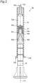
- Fig. 2 is a partial cross-sectional view of the injector.
- an injector 10 includes a barrel 12 containing, for example, a pasty fluid, a movable body 14 movably housed in the barrel 12, and a plunger 16 for pushing and moving the movable body 14.
- the injector 10 also has a nozzle tip 18 attached to a leading end 12a of the barrel 12 and a finger grip 20 rotatably fitted to a base end 12b of the barrel 12.
- Fig. 3 is a cross-sectional view of the barrel
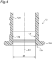
- Fig. 4 is an enlarged cross-sectional view of the barrel shown in Fig. 3 .
- the barrel 12 is a cylindrical member having a central axis C1, and is made of a resin material, for example.
- the barrel 12 includes a discharge port 12c at the leading end 12a and a flange portion 12d at the base end 12b.
- the discharge port 12c is connected to a nozzle inside flow passage communicating with the outside in the nozzle tip 18.
- the flange portion 12d functions as a stopper preventing the finger grip 20 rotatably fitted to a base end side portion of the barrel 12 from falling off.
- a circumferential groove 12f is formed in a base end side portion of an inner circumferential surface 12e of the barrel 12. The reason why the circumferential groove 12f is formed will be described later.
- Fig. 5 is a perspective view of the movable body
- Fig. 6 is a partial cross-sectional view of the movable body.
- the movable body 14 is a substantially cylindrical member having a central axis C2.
- the movable body 14 is made of an elastically deformable resin material, for example.
- the movable body 14 is made of a material easily elastically deformed as compared to the barrel 12.
- the main body 14a of the movable body 14 is cylindrical and has an outer diameter d2 smaller than an inner diameter d1 of the barrel 12 shown in Fig. 4 . Therefore, while the movable body 14 is housed in the barrel 12, a clearance is generated between the main body 14a and the inner circumferential surface 12e of the barrel 12.
- the seal body 14b of the movable body 14 has a disk shape and has an outer circumferential end brought into close contact with the inner circumferential surface 12e of the barrel 12 in a slidable and fluid-tight manner.
- the seal body 14b and the main body 14a are integrated as one part, the seal body 14b and the main body 14a may be separate parts.
- the seal body 14b For close contact of the outer circumferential end with the inner circumferential surface 12e of the barrel 12 in a fluid-tight manner, the seal body 14b has an outer diameter d3 larger than the inner diameter d1 of the barrel 12.
- the outer diameter d3 of the seal body 14b is larger than the outer diameter d2 of the main body 14a of the movable body 14.
- the seal body 14b has a central portion attached to a front end of the main body 14a (the end closer to the leading end 12a of the barrel 12). Additionally, an outer circumferential side portion of the seal body 14b is away from the main body 14a when the portion is in a free state (when the movable body 14 is present outside the barrel 12).
- the flange 14c of the movable body 14 is a projecting portion projecting from the main body toward the inner circumferential surface of the barrel 12 and is disposed at a rear end of the main body 14a (the end closer to the base end 12b of the barrel 12).
- the flange 14c has an outer diameter d4 smaller than the outer +diameter d3 of the seal body 14b.
- the outer diameter d4 of the flange 14c is smaller than the inner diameter d1 of the barrel 12 and larger than the outer diameter d2 of the main body 14a.
- the movable body 14 also includes a planar-shaped rear end surface 14d orthogonal to the central axis C2 and includes a non-penetrating hole-shaped guide hole 14e in the rear end surface 14d.
- Fig. 7 is an external view of the plunger.
- the plunger 16 is a member for pushing and moving the movable body 14 housed in the barrel 12 toward the leading end 12a (i.e., the discharge port 12c) of the barrel 12, has a central axis C3, and is made of a resin material, for example.
- the plunger 16 is configured to come into separable contact with the movable body 14.
- the plunger 16 includes a contact portion 16a coming into contact with the movable body 14 on the front end side (the side closer to the leading end 12a of the barrel 12).
- the contact portion 16a has an outer diameter d5 smaller than the inner diameter d1 of the barrel 12.
- the contact portion 16a includes a planar-shaped contact surface 16b coming into surface contact with the planar-shaped rear end surface 14d of the movable body 14.
- the plunger 16 includes a guide pin 16c projecting from the contact surface 16b of the contact portion 16a. While the rear end surface 14d of the movable body 14 is in surface contact with the contact surface 16b of the plunger 16, the guide pin 16c is received in the guide hole 14e of the movable body 14.
- An outer diameter d6 of the guide pin 16c is smaller than an inner diameter d7 of the guide hole 14e shown in Fig. 6 so that the guide pin is received in the guide hole 14e of the movable body 14 in a manner enabling forward and backward movement. Since the guide pin 16c is guided by the guide hole 14e, the contact surface 16b of the plunger 16 can appropriately come into surface contact with the rear end surface 14d of the movable body 14.
- the movable body 14 and the plunger 16 can come into contact with each other in a state in which the central axis C2 of the movable body 14 and the central axis C3 of the plunger 16 are arranged substantially on the same straight line.
- the plunger 16 can push and move the movable body 14 toward the leading end 12a of the barrel 12 without tilting.
- the plunger 16 Since the plunger 16 is not fixed to the movable body 14 while the seal body 14b is in close contact with the inner circumferential surface 12e of the barrel 12, the plunger 16 possibly comes off from the barrel 12. For example, if the injector 10 is in a state with the nozzle tip 18 located downward and a user grasps only the plunger 16 to lift the injector 10, the barrel 12 may fall off from the plunger 16 due to its own weight.
- stoppers 16d are disposed on the plunger 16 as shown in Fig. 7 .
- the two stoppers 16d are disposed oppositely to each other across the central axis C3 of the plunger 16.
- Each of the two stoppers 16d is an elastically-deformable plate spring-shaped member including a fixed end 16e attached to the plunger 16 and a free end 16f displaceable in a radial direction of the barrel 12 (a direction orthogonal to the central axis C1 of the barrel 12).
- the stoppers 16d and the plunger 16 are integrated as one part.
- the free end 16f of the stopper 16d is located on the base end 12b side of the barrel 12 with respect to the fixed end 16e.
- the free end 16f is farther than the fixed end 16e from the central axis C3 of the plunger 16. Therefore, the stopper 16d extends from the leading end 12a side to the base end 12b side of the barrel 12 and toward the inner circumferential surface 12e of the barrel 12.
- a distance L1 between the free ends 16f of the two stoppers 16d is larger than the inner diameter d1 of the barrel 12 when the free ends are in a free state (when the plunger 16 is present outside the barrel 12). Therefore, when the stoppers 16d of the plunger 16 are located inside the barrel 12, each of the two stoppers 16d is elastically deformed by the inner circumferential surface 12e of the barrel 12 such that the free ends 16f come closer to each other. This brings the free ends 16f of the stopper 16d into elastic contact with the inner circumferential surface 12e of the barrel 12 in the radial direction of the barrel 12.
- An elastic force of the stoppers 16d i.e., the friction force between the inner circumferential surface 12e of the barrel 12 and the free ends 16f of the stoppers 16d, is at a level preventing the barrel 12 from coming off when a user grasps only the plunger 16 of the injector 10 in a posture with the nozzle tip 18 located downward, or at a level preventing the plunger 16 from coming off when a user grasps only the barrel 12 of the injector 10 in a posture with the nozzle tip 18 located upward. Additionally, this elastic force (i.e., friction force) is at a level allowing the user to push and move the plunger 16 toward the leading end 12a of the barrel 12. To achieve such an elastic force (i.e., friction force), the materials of the barrel 12 and the stoppers 16d, the shape of the stoppers 16d, etc. are appropriately selected.
- the plunger 16 can be prevented from coming off from the barrel 12 without disposing a convex portion on the inner circumferential surface 12e of the barrel 12. Therefore, when the movable body 14 is housed into the barrel 12, the seal body 14b is not damaged by the convex portion disposed on the inner circumferential surface 12e.
- the plunger 16 can be anchored at an arbitrary position on the inner circumferential surface 12e of the barrel 12. As a result, the injector 10 can have high usability.
- the two stoppers 16d are arranged oppositely to each other across the central axis C3 of the plunger 16, so that the central axis C3 of the plunger 16 can be aligned with the central axis C1 of the barrel 12.
- the free ends 16f of the stoppers 16d are in elastic contact with the inner circumferential surface 12e of the barrel 12, if the user moves the plunger 16 backward, the free end 16f slides on the inner circumferential surface 12e, and the plunger 16 finally comes off from the barrel 12.
- the circumferential groove 12f is formed in a portion near the base end 12b in the inner circumferential surface 12e of the barrel 12.
- the free ends 16f of the stoppers 16d engage with (fall and fit into) the circumferential groove 12f, so that the plunger 16 is restricted from moving toward the base end side of the barrel 12, and as a result, the plunger 16 is prevented from coming off from the barrel 12.
- the circumferential groove 12f includes a slope surface 12g extending from a bottom potion thereof toward the leading end 12a of the barrel 12 and sloping with respect to the inner circumferential surface 12e. Due to the slope surface 12g, the free end 16f falling into the circumferential groove 12f can return onto the inner circumferential surface 12e. As a result, the free ends 16f of the stoppers 16d can pass through the circumferential groove 12f without being caught.
- the slope surface 12g can also prevent the seal body 14b of the movable body 14 from being caught in the circumferential groove 12f. As a result, the seal body 14b can be prevented from being damaged by the circumferential groove 12f.
- Fig. 8A is an enlarged cross-sectional view of the barrel while the plunger and the movable body are stopped.
- the seal body 14b of the movable body 14 is in close fluid-tight contact with the inner circumferential surface 12e of the barrel 12, so that a fluid F is contained in the barrel 12 without leaking from the base end side of the barrel 12 to the outside.
- Fig. 8B is an enlarged cross-sectional view of the barrel during movement of the plunger and the movable body toward the leading end of the barrel.
- Fig. 8C is an enlarged cross-sectional view of the barrel during movement of the plunger in a direction away from the movable body.
- the seal body 14b is returned (restored) to the original shape with the outer circumferential side portion separated from the main body 14a.
- the movable body 14 entirely retracts toward the base end of the barrel 12 without changing the contact position on the inner circumferential surface 12e of the barrel 12 in contact with the outer circumferential end of the seal body 14b.
- the fluid F in the nozzle tip 18 is drawn toward the seal body 14b, and the subsequent dripping of the fluid F is suppressed.
- the plunger 16 needs to retreat at the same time.
- a restoring force of the seal body 14b needs to exceed the friction force between the free ends 16f of the stoppers 16d of the plunger 16 and the inner circumferential surface 12e of the barrel 12.
- the material of the seal body 14b, the shape of the seal body 14b, etc. are appropriately selected.
- the movable body 14 retracts through the restoration of the seal body 14b without changing the position of contact of the seal body 14b with the barrel 12 as described above, the flange 14c is moved along the inner circumferential surface 12e of the barrel 12. As a result, the movable body 14 can retreat in the extending direction of the central axis C1 of the barrel 12. If the flange 14c does not exit, the movable body 14 retracts in a direction tilted with respect to the central axis C1 of the barrel 12, so that the movable body 14 may have a posture in which a portion of an outer edge of the rear end surface 14d comes into contact with the inner circumferential surface 12e of the barrel 12, i.e., a tilted posture. If the movable body 14 is tilted, the adhesion between the seal body 14b and the inner circumferential surface 12e of the barrel 12 is partially weakened, so that the fluid F may leak to the base end side of the barrel 12.
- the outer diameter d4 of the flange 14c of the movable body 14 is smaller than the inner diameter d1 of the barrel 12. Therefore, the flange 14c can be moved without strong contact with the inner circumferential surface 12e of the barrel 12, i.e., in a state of substantially zero friction force.
- the outer diameter d4 of the flange 14c of the movable body 14 may be equal to or larger than the inner diameter d1 of the barrel 12.
- the friction force between the flange 14c and the barrel 12 must be smaller than the friction force between the seal body 14b and the barrel 12. Otherwise, the restoration of the seal body 14b and the retraction of the movable body 14 due to the restoration cannot be achieved.
- the distance L2 between the seal body 14b and the flange 14c in the movable body 14 is made larger than the outer diameter d3 of the seal body 14b. Therefore, when the movable body 14 retracts due to the restoration of the seal body 14b, the movable body 14 is hardly tilted (as compared to when the distance L2 is smaller than the outer diameter d3).
- the plunger 16 separated from the movable body 14 is kept housed in the barrel 12 by the stoppers 16d without coming off from the barrel 12.
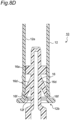
- Fig. 8D is a partially enlarged cross-sectional view of the barrel while the plunger is restricted from coming off from the barrel by the circumferential groove.
- the plunger 16 during retraction toward the base end of the barrel 12 due to pulling by the user is restrained by engagement of the free ends 16f of the stoppers 16d with the circumferential groove 12f. As a result, the plunger 16 is prevented from coming off from the barrel 12.
- the seal body and the plunger can be brought into separable contact with each other in the injector capable of suppressing the subsequent dripping of the fluid.
- Fig. 9 is an enlarged cross-sectional view of a leading end side portion of a barrel in an injector according to the second embodiment.
- Fig. 10 is an enlarged cross-sectional view of a base end side portion of the barrel.
- a plunger 116 includes stoppers 116d.
- Each of the stoppers 116d is a plate spring-shaped member including a fixed end 116e attached to the plunger 116 and a free end 116f elastically contacting the inner circumferential surface 12e of the barrel 12.
- the free end 116f of the stopper 116d is located on the leading end side of the barrel 12 with respect to the fixed end 116e. Therefore, a contact surface 116b of the plunger 116 coming into contact with the rear end surface 14d of the movable body 14 is closer to the free end 116f of the stopper 116d as compared to the first embodiment shown in Fig. 8D .
- the seal body and the plunger can be brought into separable contact with each other in the injector capable of suppressing the subsequent dripping of the fluid.
- the stoppers preventing the plunger from coming off from the barrel are disposed on the plunger.
- stoppers are disposed on the barrel. Therefore, the third embodiment will be described mainly in terms of the different stoppers.
- the same reference numerals are given to constituent elements in the third embodiment that are substantially the same as the constituent elements in the first embodiment described above.
- Fig. 11 is a partial cross-sectional view of an injector according to the third embodiment.
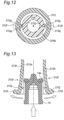
- Fig. 12 is a cross-sectional view of the injector taken along a line A-A shown in Fig. 11 .
- Fig. 13 is an enlarged cross-sectional view of a barrel, showing stoppers when the movable body is housed into the barrel. In Fig. 11 , the nozzle tip and the finger grip are not shown.
- no stopper is disposed on a plunger 216.
- a pair of stoppers 212f facing each other is disposed on a barrel 212.
- the stoppers 212f are made up of portions of the barrel 212 each interposed between two slits 212g formed to extend from a base end 212b of the barrel 212.
- a portion of the barrel 212 interposed between base portions of the two slits 212g is defined as a fixed end 212h of the stopper 212f.
- a claw 212j brought into elastic contact with the plunger 216 is disposed on the inner side of a free end 212i of each of the paired stoppers 212f.
- the stopper 212f is a plate spring-shaped member (a plate spring-shaped member integrated with the barrel 212) having the fixed end 212h attached to the barrel 212 and the free end 212i brought into elastic contact with the plunger 216 (via the claws 212j).
- a distance between the claws 212j of the pair of the stoppers 212f is made smaller than an outer diameter of a shaft portion 216b of the plunger 216.
- the pair of the claws 212j holds the shaft portion 216b of the plunger 216. Consequently, the plunger 216 is prevented from coming off from the barrel 212.
- the plunger 216 during retraction toward the base end 212b of the barrel 212 due to pulling by the user is restrained when a contact portion 216a for contact with the movable body 14 is brought into contact with the claws 212j. As a result, the plunger 216 is prevented from coming off from the barrel 212.
- the pair of the stoppers 212f is elastically deformed such that the free ends 212i move away from each other.
- the movable body 14 can be housed into the barrel 212 without bringing the claws 212j of the stoppers 212f into contact with the seal body 14b.
- the seal body and the plunger can be brought into separable contact with each other in the injector capable of suppressing the subsequent dripping of the fluid.
- the planar-shaped rear end surface 14d of the movable body 14 and the planar-shaped contact surface 16b of the plunger 16 come into separable contact with each other. Therefore, the movable body 14 and the plunger 16 are configured to come into plane contact with each other.
- the embodiments of the present invention are not limited thereto.
- the movable body may include a hemispherical concave portion at the rear end thereof, and the plunger may include a hemispherical convex portion engageable with the concave portion.
- the movable body 14 has the flange 14c disposed at the rear end of the main body 14a.
- the flange may be disposed in a portion of the main body other than the rear end.
- the seal body is preferably separated from the flange.
- At least three projecting portions disposed at regular intervals on the movable body in a circumferential direction of the main body can function as a substitute for the flange.
- a distance from the central axis of the movable body to a leading end of at least one of the projecting portions is made smaller than a half of the outer diameter of the seal body.
- the present invention is applicable to any injector for injecting a fluid as long as the injector has a seal body and a plunger brought into separable contact with each other.
Landscapes
- Health & Medical Sciences (AREA)
- Engineering & Computer Science (AREA)
- Hematology (AREA)
- Life Sciences & Earth Sciences (AREA)
- Vascular Medicine (AREA)
- Anesthesiology (AREA)
- Biomedical Technology (AREA)
- Heart & Thoracic Surgery (AREA)
- Veterinary Medicine (AREA)
- Public Health (AREA)
- Animal Behavior & Ethology (AREA)
- General Health & Medical Sciences (AREA)
- General Engineering & Computer Science (AREA)
- Mechanical Engineering (AREA)
- Fuel-Injection Apparatus (AREA)
- Infusion, Injection, And Reservoir Apparatuses (AREA)
- Dental Tools And Instruments Or Auxiliary Dental Instruments (AREA)
Description
- The present invention relates to an injector.
- An injector for injecting a fluid is conventionally known. For example, the injector described in Patent Document 1 is configured such that after pushing out a necessary amount of fluid through a discharge port to the outside of a barrel, the fluid remaining inside the barrel does not leak automatically through the discharge port, i.e., "subsequent dripping" of the fluid does not occur.
- Specifically, in the case of the injector described in Patent Document 1, a disk-shaped seal body is integrally disposed at a front end of a plunger. An outer circumferential end of the seal body is in close contact with an inner circumferential surface of the barrel.
- When the plunger advances toward the discharge port of the barrel, the disk-shaped seal body pushes and moves the fluid toward the discharge port while elastically deforms into a closed umbrella shape. When the plunger stops, the seal body returns from the closed umbrella shape to the disk shape. In this case, a central portion of the seal body is shifted in a direction away from the discharge port without changing a position of the inner circumferential surface of the barrel at which the outer circumferential end of the seal body is in contact. As a result, the fluid is drawn toward the seal body, and the subsequent dripping of the fluid is suppressed.
- Patent Document 2 discloses a plastic injection molded plunger for a medical syringe and a medical syringe having such plunger, wherein the plunger comprises one or more sealing, and, in cross-section, a sealing lip is furthermore angled toward the front or the rear in an advancement direction for the discharge of liquid from the syringe during use. A channel is formed with respect to a central region of the plunger, which channel, viewed in cross-section, projects radially beyond the largest plunger diameter.
- Patent Document 3 discloses a stopper adapted for attachment with a plunger rod for use within a syringe barrel including a main body portion defining an open rearward end configured to receive the plunger rod.
- Patent Document 4 discloses a plunger for use in a syringe and a syringe comprising such a plunger. The plunger includes a pressure member extending around the circumference of a generally cylindrical body of the plunger. The pressure member is in substantially sealing contact with the plunger body. The pressure member forms a substantially sealing engagement with the inner wall of the syringe. Further, the pressure member comprises a flange attached at a rearward portion of the flange to a body of the plunger. The flange extends forward and radially outward to form a circumferential channel between the flange and the body of the plunger.
-
- Patent Document 1:
Japanese Laid-Open Patent Publication No. 2003-135487 - Patent Document 2:
PCT patent application publication No. 2018/083221 A1 - Patent Document 3:
US patent application publication No. 2012/253291 A1 - Patent Document 4:
US patent publication No. 6 224 577 B1 - To prevent the seal body closely contact with the inner circumferential surface of the barrel from coming off to the outside of the barrel, an injector having the seal body and the plunger coming into separable contact with each other is required. This allows the seal body to remain in the barrel without retracting even if the plunger is retracted. As a result, air is prevented from entering the fluid in the barrel from the base end side of the barrel. This also prevents air from entering from the discharge port due to retracting of the seal body.
- Therefore, a problem to be solved by the present invention is to bring a seal body and a plunger into separable contact with each other in an injector capable of suppressing subsequent dripping of a fluid.
- To solve the problem described above, the present invention provides an injector as defined in appended claim 1.
- According to the present invention, the seal body and the plunger can be brought into separable contact with each other in the injector capable of suppressing subsequent dripping of a fluid.
-
-
Fig. 1 is an external view of an injector according to a first embodiment of the present invention. -
Fig. 2 is a partial cross-sectional view of the injector according to the first embodiment. -
Fig. 3 is a cross-sectional view of a barrel in the injector according to the first embodiment. -
Fig. 4 is an enlarged cross-sectional view of the barrel shown inFig. 3 . -
Fig. 5 is a perspective view of a movable body in the injector according to the first embodiment. -
Fig. 6 is a partial cross-sectional view of the movable body shown inFig. 5 . -
Fig. 7 is an external view of a plunger in the injector according to the first embodiment. -
Fig. 8A is an enlarged cross-sectional view of the barrel while the plunger and the movable body are stopped. -
Fig. 8B is an enlarged cross-sectional view of the barrel during movement of the plunger and the movable body toward a leading end of the barrel. -
Fig. 8C is an enlarged cross-sectional view of the barrel during movement of the plunger in a direction away from the movable body. -
Fig. 8D is an enlarged cross-sectional view of the barrel while the plunger is restricted from coming off from the barrel by a circumferential groove. -
Fig. 9 is an enlarged cross-sectional view of a leading end portion of a barrel in an injector according to a second embodiment of the present invention. -
Fig. 10 is an enlarged cross-sectional view of a base end side portion of the barrel in the injector according to the second embodiment. -
Fig. 11 is a partial cross-sectional view of an injector according to a third embodiment of the present invention. -
Fig. 12 is a cross-sectional view of the injector taken along a line A-A shown inFig. 11 . -
Fig. 13 is an enlarged cross-sectional view of a barrel, showing stoppers when the movable body is housed in the barrel. - An injector according to the present invention comprises a cylindrical barrel, a movable body housed in the barrel, and a plunger coming into separable contact with the movable body; the movable body includes a main body having an outer diameter smaller than an inner diameter of the barrel, a disk-shaped seal body attached to a front end of the main body and including an outer circumferential end brought into close contact with an inner circumferential surface of the barrel, and at least one projecting portion projecting from the main body toward the inner circumferential surface of the barrel; and a distance from a central axis of the movable body to a leading end of the at least one projecting portion is smaller than a half of an outer diameter of the seal body. Further, the movable body and the plunger are configured to separate from each other by retracting the plunger
- According to the present invention, the seal body and the plunger can be brought into separable contact with each other in the injector capable of suppressing subsequent dripping of a fluid.
- The at least one projecting portion may be a flange. In this case, an outer diameter of the flange is made smaller than the outer diameter of the seal body.
- The outer diameter of the flange may be smaller than the inner diameter of the barrel. As a result, the flange can be moved without strong contact with the inner circumferential surface of the barrel, i.e., in a state of substantially zero friction force.
- A distance between the seal body and the flange may be larger than the outer diameter of the seal body. As a result, the movable body is restrained from tilting.
- The plunger may include a planar-shaped contact surface at a front end thereof, and the movable body may include a planar-shaped rear end surface coming into contact with the contact surface of the plunger. As a result, the movable body can be pushed and moved by the plunger without tilting.
- The plunger may include a guide pin projecting from the contact surface, and the movable body may include in the rear end surface a guide hole receiving the guide pin in a manner enabling forward and backward movement. Since the guide pin is guided by the guide hole, the rear end surface of the movable body and the contact surface of the plunger can appropriately contact with each other.
- Embodiments of the present invention will now be described with reference to the drawings.
-
Fig. 1 is an external view of an injector according to a first embodiment of the present invention, andFig. 2 is a partial cross-sectional view of the injector. - As shown in
Figs. 1 and2 , aninjector 10 includes abarrel 12 containing, for example, a pasty fluid, amovable body 14 movably housed in thebarrel 12, and aplunger 16 for pushing and moving themovable body 14. Theinjector 10 also has anozzle tip 18 attached to aleading end 12a of thebarrel 12 and afinger grip 20 rotatably fitted to abase end 12b of thebarrel 12. -
Fig. 3 is a cross-sectional view of the barrel, andFig. 4 is an enlarged cross-sectional view of the barrel shown inFig. 3 . - As shown in
Fig. 3 , thebarrel 12 is a cylindrical member having a central axis C1, and is made of a resin material, for example. Thebarrel 12 includes adischarge port 12c at theleading end 12a and aflange portion 12d at thebase end 12b. By attaching thenozzle tip 18 to theleading end 12a of thebarrel 12, thedischarge port 12c is connected to a nozzle inside flow passage communicating with the outside in thenozzle tip 18. Theflange portion 12d functions as a stopper preventing thefinger grip 20 rotatably fitted to a base end side portion of thebarrel 12 from falling off. - As shown in
Fig. 4 , acircumferential groove 12f is formed in a base end side portion of an innercircumferential surface 12e of thebarrel 12. The reason why thecircumferential groove 12f is formed will be described later. -
Fig. 5 is a perspective view of the movable body, andFig. 6 is a partial cross-sectional view of the movable body. - As shown in
Fig. 5 , themovable body 14 is a substantially cylindrical member having a central axis C2. Themovable body 14 is made of an elastically deformable resin material, for example. Specifically, themovable body 14 is made of a material easily elastically deformed as compared to thebarrel 12. - The
movable body 14 includes amain body 14a, aseal body 14b disposed on themain body 14a, and aflange 14c disposed on themain body 14a. - The
main body 14a of themovable body 14 is cylindrical and has an outer diameter d2 smaller than an inner diameter d1 of thebarrel 12 shown inFig. 4 . Therefore, while themovable body 14 is housed in thebarrel 12, a clearance is generated between themain body 14a and the innercircumferential surface 12e of thebarrel 12. - The
seal body 14b of themovable body 14 has a disk shape and has an outer circumferential end brought into close contact with the innercircumferential surface 12e of thebarrel 12 in a slidable and fluid-tight manner. Although theseal body 14b and themain body 14a are integrated as one part, theseal body 14b and themain body 14a may be separate parts. - For close contact of the outer circumferential end with the inner
circumferential surface 12e of thebarrel 12 in a fluid-tight manner, theseal body 14b has an outer diameter d3 larger than the inner diameter d1 of thebarrel 12. The outer diameter d3 of theseal body 14b is larger than the outer diameter d2 of themain body 14a of themovable body 14. - Additionally, the
seal body 14b has a central portion attached to a front end of themain body 14a (the end closer to theleading end 12a of the barrel 12). Additionally, an outer circumferential side portion of theseal body 14b is away from themain body 14a when the portion is in a free state (when themovable body 14 is present outside the barrel 12). - The
flange 14c of themovable body 14 is a projecting portion projecting from the main body toward the inner circumferential surface of thebarrel 12 and is disposed at a rear end of themain body 14a (the end closer to thebase end 12b of the barrel 12). Theflange 14c has an outer diameter d4 smaller than the outer +diameter d3 of theseal body 14b. In the case of the first embodiment, the outer diameter d4 of theflange 14c is smaller than the inner diameter d1 of thebarrel 12 and larger than the outer diameter d2 of themain body 14a. The reason why theflange 14c as described above is disposed on themovable body 14 will be described later. - For separable contact with the
plunger 16, themovable body 14 also includes a planar-shapedrear end surface 14d orthogonal to the central axis C2 and includes a non-penetrating hole-shapedguide hole 14e in therear end surface 14d. -
Fig. 7 is an external view of the plunger. - As shown in
Fig. 7 , theplunger 16 is a member for pushing and moving themovable body 14 housed in thebarrel 12 toward theleading end 12a (i.e., thedischarge port 12c) of thebarrel 12, has a central axis C3, and is made of a resin material, for example. Theplunger 16 is configured to come into separable contact with themovable body 14. - Specifically, the
plunger 16 includes acontact portion 16a coming into contact with themovable body 14 on the front end side (the side closer to theleading end 12a of the barrel 12). Thecontact portion 16a has an outer diameter d5 smaller than the inner diameter d1 of thebarrel 12. Thecontact portion 16a includes a planar-shapedcontact surface 16b coming into surface contact with the planar-shapedrear end surface 14d of themovable body 14. - The
plunger 16 includes aguide pin 16c projecting from thecontact surface 16b of thecontact portion 16a. While therear end surface 14d of themovable body 14 is in surface contact with thecontact surface 16b of theplunger 16, theguide pin 16c is received in theguide hole 14e of themovable body 14. An outer diameter d6 of theguide pin 16c is smaller than an inner diameter d7 of theguide hole 14e shown inFig. 6 so that the guide pin is received in theguide hole 14e of themovable body 14 in a manner enabling forward and backward movement. Since theguide pin 16c is guided by theguide hole 14e, thecontact surface 16b of theplunger 16 can appropriately come into surface contact with therear end surface 14d of themovable body 14. Specifically, themovable body 14 and theplunger 16 can come into contact with each other in a state in which the central axis C2 of themovable body 14 and the central axis C3 of theplunger 16 are arranged substantially on the same straight line. As a result, theplunger 16 can push and move themovable body 14 toward theleading end 12a of thebarrel 12 without tilting. - According to the
plunger 16 as described above, themovable body 14 can be pushed and moved toward theleading end 12a of thebarrel 12 by advancing theplunger 16. Additionally, themovable body 14 and theplunger 16 can be separated from each other by simply retracting theplunger 16. - Since the
plunger 16 is not fixed to themovable body 14 while theseal body 14b is in close contact with the innercircumferential surface 12e of thebarrel 12, theplunger 16 possibly comes off from thebarrel 12. For example, if theinjector 10 is in a state with thenozzle tip 18 located downward and a user grasps only theplunger 16 to lift theinjector 10, thebarrel 12 may fall off from theplunger 16 due to its own weight. - To prevent the
plunger 16 from coming off from thebarrel 12 in this way,stoppers 16d are disposed on theplunger 16 as shown inFig. 7 . - In the case of the first embodiment, the two
stoppers 16d are disposed oppositely to each other across the central axis C3 of theplunger 16. Each of the twostoppers 16d is an elastically-deformable plate spring-shaped member including afixed end 16e attached to theplunger 16 and afree end 16f displaceable in a radial direction of the barrel 12 (a direction orthogonal to the central axis C1 of the barrel 12). In the case of the first embodiment, thestoppers 16d and theplunger 16 are integrated as one part. - In the case of the first embodiment, the
free end 16f of thestopper 16d is located on thebase end 12b side of thebarrel 12 with respect to thefixed end 16e. Thefree end 16f is farther than thefixed end 16e from the central axis C3 of theplunger 16. Therefore, thestopper 16d extends from theleading end 12a side to thebase end 12b side of thebarrel 12 and toward the innercircumferential surface 12e of thebarrel 12. - As shown in
Fig. 7 , a distance L1 between the free ends 16f of the twostoppers 16d is larger than the inner diameter d1 of thebarrel 12 when the free ends are in a free state (when theplunger 16 is present outside the barrel 12). Therefore, when thestoppers 16d of theplunger 16 are located inside thebarrel 12, each of the twostoppers 16d is elastically deformed by the innercircumferential surface 12e of thebarrel 12 such that the free ends 16f come closer to each other. This brings the free ends 16f of thestopper 16d into elastic contact with the innercircumferential surface 12e of thebarrel 12 in the radial direction of thebarrel 12. As a result, a friction force is generated between thebarrel 12 and the free ends 16f of thestopper 16d, and theplunger 16 is restrained from coming off from thebarrel 12. The term "elastic contact" as used herein means that a portion of an object during elastic deformation is in contact with another object in a restoring direction in which the object is restored to an original shape. - An elastic force of the
stoppers 16d, i.e., the friction force between the innercircumferential surface 12e of thebarrel 12 and the free ends 16f of thestoppers 16d, is at a level preventing thebarrel 12 from coming off when a user grasps only theplunger 16 of theinjector 10 in a posture with thenozzle tip 18 located downward, or at a level preventing theplunger 16 from coming off when a user grasps only thebarrel 12 of theinjector 10 in a posture with thenozzle tip 18 located upward. Additionally, this elastic force (i.e., friction force) is at a level allowing the user to push and move theplunger 16 toward theleading end 12a of thebarrel 12. To achieve such an elastic force (i.e., friction force), the materials of thebarrel 12 and thestoppers 16d, the shape of thestoppers 16d, etc. are appropriately selected. - According to the
stoppers 16d as described above, theplunger 16 can be prevented from coming off from thebarrel 12 without disposing a convex portion on the innercircumferential surface 12e of thebarrel 12. Therefore, when themovable body 14 is housed into thebarrel 12, theseal body 14b is not damaged by the convex portion disposed on the innercircumferential surface 12e. - According to the
stoppers 16d as described above, theplunger 16 can be anchored at an arbitrary position on the innercircumferential surface 12e of thebarrel 12. As a result, theinjector 10 can have high usability. - Furthermore, in the case of the first embodiment, the two
stoppers 16d are arranged oppositely to each other across the central axis C3 of theplunger 16, so that the central axis C3 of theplunger 16 can be aligned with the central axis C1 of thebarrel 12. - Although the free ends 16f of the
stoppers 16d are in elastic contact with the innercircumferential surface 12e of thebarrel 12, if the user moves theplunger 16 backward, thefree end 16f slides on the innercircumferential surface 12e, and theplunger 16 finally comes off from thebarrel 12. To deal with such coming-off due to the user, as shown inFig. 4 , thecircumferential groove 12f is formed in a portion near thebase end 12b in the innercircumferential surface 12e of thebarrel 12. The free ends 16f of thestoppers 16d engage with (fall and fit into) thecircumferential groove 12f, so that theplunger 16 is restricted from moving toward the base end side of thebarrel 12, and as a result, theplunger 16 is prevented from coming off from thebarrel 12. - When the
plunger 16 is housed into thebarrel 12, the free ends 16f of thestoppers 16d may be caught in thecircumferential groove 12f, which possibly makes it unable to smoothly move theplunger 16 toward theleading end 12a of thebarrel 12. As a countermeasure, as shown inFig. 4 , thecircumferential groove 12f includes aslope surface 12g extending from a bottom potion thereof toward theleading end 12a of thebarrel 12 and sloping with respect to the innercircumferential surface 12e. Due to theslope surface 12g, thefree end 16f falling into thecircumferential groove 12f can return onto the innercircumferential surface 12e. As a result, the free ends 16f of thestoppers 16d can pass through thecircumferential groove 12f without being caught. - When the
movable body 14 is housed into thebarrel 12, theslope surface 12g can also prevent theseal body 14b of themovable body 14 from being caught in thecircumferential groove 12f. As a result, theseal body 14b can be prevented from being damaged by thecircumferential groove 12f. - While describing the operation of the
injector 10 according to the first embodiment, other features of theinjector 10 will hereinafter be described with reference toFigs. 8A to 8D . -
Fig. 8A is an enlarged cross-sectional view of the barrel while the plunger and the movable body are stopped. - As shown in
Fig. 8A , theseal body 14b of themovable body 14 is in close fluid-tight contact with the innercircumferential surface 12e of thebarrel 12, so that a fluid F is contained in thebarrel 12 without leaking from the base end side of thebarrel 12 to the outside. -
Fig. 8B is an enlarged cross-sectional view of the barrel during movement of the plunger and the movable body toward the leading end of the barrel. - As shown in
Fig. 8B , while therear end surface 14d of themovable body 14 and thecontact surface 16b of theplunger 16 are in contact with each other, themovable body 14 is pushed and moved toward theleading end 12a of thebarrel 12 by theplunger 16. During movement of themovable body 14, theseal body 14b is elastically deformed. Specifically, due to the friction force generated between the outer circumferential end of theseal body 14b and the innercircumferential surface 12e of thebarrel 12, theseal body 14b is elastically deformed such that the outer circumferential side portion of theseal body 14b approaches themain body 14a. Theseal body 14b moves in this elastically deformed state and pushes and moves the fluid F toward thedischarge port 12c. -
Fig. 8C is an enlarged cross-sectional view of the barrel during movement of the plunger in a direction away from the movable body. - As shown in
Fig. 8C , when theplunger 16 moves in a direction away from themovable body 14, i.e., toward the base end of thebarrel 12, themovable body 14 is separated from theplunger 16 and stops in thebarrel 12 in this state. - Immediately after the
movable body 14 stops, as shown inFig. 8A , theseal body 14b is returned (restored) to the original shape with the outer circumferential side portion separated from themain body 14a. In this case, themovable body 14 entirely retracts toward the base end of thebarrel 12 without changing the contact position on the innercircumferential surface 12e of thebarrel 12 in contact with the outer circumferential end of theseal body 14b. As a result, the fluid F in thenozzle tip 18 is drawn toward theseal body 14b, and the subsequent dripping of the fluid F is suppressed. - To allow the
movable body 14 to retract toward the base end of thebarrel 12 through the restoration of theseal body 14b without changing the position of contact of theseal body 14b with thebarrel 12, theplunger 16 needs to retreat at the same time. In other words, a restoring force of theseal body 14b needs to exceed the friction force between the free ends 16f of thestoppers 16d of theplunger 16 and the innercircumferential surface 12e of thebarrel 12. For this purpose, the material of theseal body 14b, the shape of theseal body 14b, etc. are appropriately selected. - When the
movable body 14 retracts through the restoration of theseal body 14b without changing the position of contact of theseal body 14b with thebarrel 12 as described above, theflange 14c is moved along the innercircumferential surface 12e of thebarrel 12. As a result, themovable body 14 can retreat in the extending direction of the central axis C1 of thebarrel 12. If theflange 14c does not exit, themovable body 14 retracts in a direction tilted with respect to the central axis C1 of thebarrel 12, so that themovable body 14 may have a posture in which a portion of an outer edge of therear end surface 14d comes into contact with the innercircumferential surface 12e of thebarrel 12, i.e., a tilted posture. If themovable body 14 is tilted, the adhesion between theseal body 14b and the innercircumferential surface 12e of thebarrel 12 is partially weakened, so that the fluid F may leak to the base end side of thebarrel 12. - In the case of the first embodiment, the outer diameter d4 of the
flange 14c of themovable body 14 is smaller than the inner diameter d1 of thebarrel 12. Therefore, theflange 14c can be moved without strong contact with the innercircumferential surface 12e of thebarrel 12, i.e., in a state of substantially zero friction force. Alternatively, the outer diameter d4 of theflange 14c of themovable body 14 may be equal to or larger than the inner diameter d1 of thebarrel 12. However, the friction force between theflange 14c and thebarrel 12 must be smaller than the friction force between theseal body 14b and thebarrel 12. Otherwise, the restoration of theseal body 14b and the retraction of themovable body 14 due to the restoration cannot be achieved. - In the case of the first embodiment, as shown in
Fig. 6 , the distance L2 between theseal body 14b and theflange 14c in themovable body 14 is made larger than the outer diameter d3 of theseal body 14b. Therefore, when themovable body 14 retracts due to the restoration of theseal body 14b, themovable body 14 is hardly tilted (as compared to when the distance L2 is smaller than the outer diameter d3). - As shown in
Fig. 8C , theplunger 16 separated from themovable body 14 is kept housed in thebarrel 12 by thestoppers 16d without coming off from thebarrel 12. -
Fig. 8D is a partially enlarged cross-sectional view of the barrel while the plunger is restricted from coming off from the barrel by the circumferential groove. - As shown in
Fig. 8D , theplunger 16 during retraction toward the base end of thebarrel 12 due to pulling by the user is restrained by engagement of the free ends 16f of thestoppers 16d with thecircumferential groove 12f. As a result, theplunger 16 is prevented from coming off from thebarrel 12. - According to the first embodiment as described above, the seal body and the plunger can be brought into separable contact with each other in the injector capable of suppressing the subsequent dripping of the fluid.
- A second embodiment is substantially the same as the first embodiment as descried above except that the form of the stoppers disposed on the plunger is different. Therefore, the second embodiment will be described mainly in terms of different points. The same reference numerals are given to constituent elements in the second embodiment that are substantially the same as the constituent elements in the first embodiment described above.
-
Fig. 9 is an enlarged cross-sectional view of a leading end side portion of a barrel in an injector according to the second embodiment.Fig. 10 is an enlarged cross-sectional view of a base end side portion of the barrel. - As shown in
Fig. 9 , in aninjector 110 according to the second embodiment, aplunger 116 includesstoppers 116d. Each of thestoppers 116d is a plate spring-shaped member including afixed end 116e attached to theplunger 116 and afree end 116f elastically contacting the innercircumferential surface 12e of thebarrel 12. - In the case of the second embodiment, unlike the
stopper 16d of the first embodiment, thefree end 116f of thestopper 116d is located on the leading end side of thebarrel 12 with respect to thefixed end 116e. Therefore, acontact surface 116b of theplunger 116 coming into contact with therear end surface 14d of themovable body 14 is closer to thefree end 116f of thestopper 116d as compared to the first embodiment shown inFig. 8D . - Thus, as shown in
Fig. 10 , when thefree end 116f of thestopper 116d is engaged with the circumferential groove of thebarrel 12, thecontact surface 116b of theplunger 116 is located closer to thebase end 12b of thebarrel 12. In other words, themovable body 14 having therear end surface 14d brought into contact with thecontact surface 116b is also disposed closer to thebase end 12b of thebarrel 12. As a result, a larger amount of the fluid can be contained in thebarrel 12. - In the second embodiment as described above, as with the first embodiment, the seal body and the plunger can be brought into separable contact with each other in the injector capable of suppressing the subsequent dripping of the fluid.
- In the case of the first embodiment described above, the stoppers preventing the plunger from coming off from the barrel are disposed on the plunger. In contrast, in the case of a third embodiment, stoppers are disposed on the barrel. Therefore, the third embodiment will be described mainly in terms of the different stoppers. The same reference numerals are given to constituent elements in the third embodiment that are substantially the same as the constituent elements in the first embodiment described above.
-
Fig. 11 is a partial cross-sectional view of an injector according to the third embodiment.Fig. 12 is a cross-sectional view of the injector taken along a line A-A shown inFig. 11 .Fig. 13 is an enlarged cross-sectional view of a barrel, showing stoppers when the movable body is housed into the barrel. InFig. 11 , the nozzle tip and the finger grip are not shown. - As shown in
Figs. 11 and12 , in aninjector 210 according to the third embodiment, no stopper is disposed on aplunger 216. Instead, as shown inFig. 12 , a pair ofstoppers 212f facing each other is disposed on abarrel 212. - Specifically, in the case of the third embodiment, the
stoppers 212f are made up of portions of thebarrel 212 each interposed between twoslits 212g formed to extend from abase end 212b of thebarrel 212. As a result, a portion of thebarrel 212 interposed between base portions of the twoslits 212g is defined as afixed end 212h of thestopper 212f. Aclaw 212j brought into elastic contact with theplunger 216 is disposed on the inner side of afree end 212i of each of the pairedstoppers 212f. Therefore, thestopper 212f is a plate spring-shaped member (a plate spring-shaped member integrated with the barrel 212) having thefixed end 212h attached to thebarrel 212 and thefree end 212i brought into elastic contact with the plunger 216 (via theclaws 212j). - A distance between the
claws 212j of the pair of thestoppers 212f is made smaller than an outer diameter of ashaft portion 216b of theplunger 216. As a result, the pair of theclaws 212j holds theshaft portion 216b of theplunger 216. Consequently, theplunger 216 is prevented from coming off from thebarrel 212. - The
plunger 216 during retraction toward thebase end 212b of thebarrel 212 due to pulling by the user is restrained when acontact portion 216a for contact with themovable body 14 is brought into contact with theclaws 212j. As a result, theplunger 216 is prevented from coming off from thebarrel 212. - As shown in
Fig. 13 , when themovable body 14 is housed into thebarrel 212, the pair of thestoppers 212f is elastically deformed such that the free ends 212i move away from each other. As a result, themovable body 14 can be housed into thebarrel 212 without bringing theclaws 212j of thestoppers 212f into contact with theseal body 14b. - In the third embodiment as described above, as with the first embodiment, the seal body and the plunger can be brought into separable contact with each other in the injector capable of suppressing the subsequent dripping of the fluid.
- Although the present invention has been described with three embodiments, the present invention is not limited to these embodiments.
- For example, in the case of the first embodiment, as shown in
Fig. 8A , the planar-shapedrear end surface 14d of themovable body 14 and the planar-shapedcontact surface 16b of theplunger 16 come into separable contact with each other. Therefore, themovable body 14 and theplunger 16 are configured to come into plane contact with each other. However, the embodiments of the present invention are not limited thereto. For example, the movable body may include a hemispherical concave portion at the rear end thereof, and the plunger may include a hemispherical convex portion engageable with the concave portion. - In the case of the first embodiment described above, as shown in
Fig. 6 , themovable body 14 has theflange 14c disposed at the rear end of themain body 14a. The flange may be disposed in a portion of the main body other than the rear end. However, to suppress the tilt of the movable body, the seal body is preferably separated from the flange. - Regarding the flange, at least three projecting portions disposed at regular intervals on the movable body in a circumferential direction of the main body can function as a substitute for the flange. In this case, a distance from the central axis of the movable body to a leading end of at least one of the projecting portions is made smaller than a half of the outer diameter of the seal body.
- The present invention is applicable to any injector for injecting a fluid as long as the injector has a seal body and a plunger brought into separable contact with each other.
-
- 10
- injector
- 12
- barrel
- 12e
- inner circumferential surface
- 14
- movable body
- 14a
- main body
- 14b
- seal body
- 14c
- at least one projecting portion (flange)
- 16
- plunger
Claims (6)
- An injector (10, 110, 210) comprising:a cylindrical barrel (12, 212);a movable body (14) housed in the barrel (12, 212); anda plunger (16, 116, 216) coming into separable contact with the movable body (14),wherein the movable body (14) includesa main body (14a) having an outer diameter smaller than an inner diameter of the barrel (12, 212),a disk-shaped seal body (14b) attached to a front end of the main body (14a) and including an outer circumferential end brought into close contact with an inner circumferential surface (12e) of the barrel (12, 212), andat least one projecting portion (14c) projecting from the main body (14a) toward the inner circumferential surface (12e) of the barrel (12, 212),wherein a distance from a central axis of the movable body (14) to a leading end of the at least one projecting portion (14c) is smaller than a half of an outer diameter of the seal body (14b), andwherein the movable body (14) and the plunger (16, 116, 216) are configured to separate from each other by retracting the plunger (16, 116, 216),characterized in that a pair of stoppers (16d, 116d, 212f) are disposed on one of the barrel (12, 212) and the plunger (16, 116, 216), and the stoppers (16d, 116d, 212f) come into elastic contact with the other one of the barrel (12, 212) and the plunger (16, 116, 216) in a radial direction of the barrel (12, 212).
- The injector (10, 110, 210) according to claim 1, whereinthe at least one projecting portion (14c) is a flange (14c), and whereinan outer diameter of the flange (14c) is smaller than the outer diameter of the seal body (14b).
- The injector (10, 110, 210) according to claim 2, wherein the outer diameter of the flange (14c) is smaller than the inner diameter of the barrel (12, 212).
- The injector (10, 110, 210) according to claim 2 or 3, wherein a distance between the seal body (14b) and the flange (14c) is larger than the outer diameter of the seal body (14b).
- The injector (10, 110, 210) according to any one of claims 1 to 4, whereinthe plunger (16, 116, 216) includes a planar-shaped contact surface (16b) at a front end thereof, and whereinthe movable body (14) includes a planar-shaped rear end surface (14d) coming into contact with the contact surface (16b) of the plunger (16, 116, 216).
- The injector (10, 110, 210) according to claim 5, whereinthe plunger (16, 116, 216) includes a guide pin (16c) projecting from the contact surface (16b), and whereinthe movable body (14) includes in the rear end surface (14d) a guide hole (14e) receiving the guide pin (16c) in a manner enabling forward and backward movement.
Applications Claiming Priority (1)
| Application Number | Priority Date | Filing Date | Title |
|---|---|---|---|
| JP2018118257A JP7593581B2 (en) | 2018-06-21 | 2018-06-21 | Injector |
Publications (2)
| Publication Number | Publication Date |
|---|---|
| EP3586895A1 EP3586895A1 (en) | 2020-01-01 |
| EP3586895B1 true EP3586895B1 (en) | 2025-05-14 |
Family
ID=66998281
Family Applications (1)
| Application Number | Title | Priority Date | Filing Date |
|---|---|---|---|
| EP19181133.0A Active EP3586895B1 (en) | 2018-06-21 | 2019-06-19 | Injector |
Country Status (4)
| Country | Link |
|---|---|
| US (1) | US11679202B2 (en) |
| EP (1) | EP3586895B1 (en) |
| JP (1) | JP7593581B2 (en) |
| CN (1) | CN110630489B (en) |
Families Citing this family (1)
| Publication number | Priority date | Publication date | Assignee | Title |
|---|---|---|---|---|
| CN115962995B (en) * | 2022-12-26 | 2023-07-04 | 中国科学院基础医学与肿瘤研究所(筹) | Full-automatic microorganism dyeing film-making device |
Citations (1)
| Publication number | Priority date | Publication date | Assignee | Title |
|---|---|---|---|---|
| US5620423A (en) * | 1993-09-23 | 1997-04-15 | Heraeus Kulzer Gmbh | Syringe for the controlled discharge of viscous materials |
Family Cites Families (23)
| Publication number | Priority date | Publication date | Assignee | Title |
|---|---|---|---|---|
| US3809082A (en) * | 1971-12-30 | 1974-05-07 | Ampoules Inc | Plunger tack |
| CH620126A5 (en) | 1978-03-10 | 1980-11-14 | Tulcea Sa | |
| JPS5616083A (en) | 1979-07-19 | 1981-02-16 | Kushida Fumio | Crucible |
| JPS6222634A (en) | 1985-07-23 | 1987-01-30 | 松下電器産業株式会社 | Ultrasonic probe |
| WO1989006146A1 (en) | 1987-12-30 | 1989-07-13 | Jacques Verlier | Non-reusable syringe |
| MY104360A (en) | 1987-12-30 | 1994-03-31 | Verlier Jacques | Non-reusable syringe |
| US5875976A (en) | 1996-12-24 | 1999-03-02 | Medi-Ject Corporation | Locking mechanism for nozzle assembly |
| US6224577B1 (en) * | 1998-03-02 | 2001-05-01 | Medrad, Inc. | Syringes and plungers for use therein |
| JP4434342B2 (en) | 1998-09-28 | 2010-03-17 | 昭和薬品化工株式会社 | Cartridge dental syringe |
| JP4133071B2 (en) | 2001-08-20 | 2008-08-13 | 大成化工株式会社 | Anti-sagging injector, and plunger and seal body for the injector |
| JP2003210578A (en) | 2002-01-23 | 2003-07-29 | Asahi Kasei Corp | Piston-loading method |
| JP4738420B2 (en) * | 2004-12-21 | 2011-08-03 | ベクトン・ディキンソン・アンド・カンパニー | Syringe assembly with disabling mechanism |
| WO2006087762A1 (en) * | 2005-02-15 | 2006-08-24 | Kabushiki Kaisha Top | Syringe |
| US8740856B2 (en) * | 2007-06-04 | 2014-06-03 | Becton, Dickinson And Company | Stoppers used in pre-filled syringes |
| JP2013509270A (en) | 2009-10-29 | 2013-03-14 | ゴア エンタープライズ ホールディングス,インコーポレイティド | Syringe stopper covered with expanded PTFE |
| US8574201B2 (en) | 2009-12-22 | 2013-11-05 | Medtronic Minimed, Inc. | Syringe piston with check valve seal |
| DE102010015417A1 (en) * | 2010-04-19 | 2011-10-20 | Robert Bosch Gmbh | Piston for a radial piston machine |
| EP3326674B1 (en) * | 2011-03-28 | 2020-08-19 | Becton, Dickinson and Company | Plastic stopper |
| PT3858405T (en) | 2012-06-01 | 2023-06-26 | Novartis Ag | Syringe |
| JP6199604B2 (en) * | 2013-05-15 | 2017-09-20 | 住友ゴム工業株式会社 | Medical gasket |
| JP6270538B2 (en) * | 2014-02-27 | 2018-01-31 | 株式会社トクヤマデンタル | Dispenser |
| CN108025136B (en) | 2015-09-11 | 2020-10-23 | 西医药服务有限公司 | Medical applicator cartridge with groove and method of sealing the same |
| DE102017125703A1 (en) * | 2016-11-04 | 2018-05-09 | Datwyler Pharma Packaging International Nv | A plastic syringe made of a syringe for a medical syringe and a medical syringe |
-
2018
- 2018-06-21 JP JP2018118257A patent/JP7593581B2/en active Active
-
2019
- 2019-06-19 EP EP19181133.0A patent/EP3586895B1/en active Active
- 2019-06-20 US US16/447,227 patent/US11679202B2/en active Active
- 2019-06-20 CN CN201910536167.2A patent/CN110630489B/en active Active
Patent Citations (1)
| Publication number | Priority date | Publication date | Assignee | Title |
|---|---|---|---|---|
| US5620423A (en) * | 1993-09-23 | 1997-04-15 | Heraeus Kulzer Gmbh | Syringe for the controlled discharge of viscous materials |
Also Published As
| Publication number | Publication date |
|---|---|
| JP2019217105A (en) | 2019-12-26 |
| EP3586895A1 (en) | 2020-01-01 |
| CN110630489A (en) | 2019-12-31 |
| US11679202B2 (en) | 2023-06-20 |
| JP7593581B2 (en) | 2024-12-03 |
| US20190388620A1 (en) | 2019-12-26 |
| CN110630489B (en) | 2023-03-21 |
Similar Documents
| Publication | Publication Date | Title |
|---|---|---|
| CN112516420B (en) | Device for locking the plunger rod of a used syringe and preventing the syringe from being reused and syringe assembly | |
| KR102414648B1 (en) | Dosing assembly for drug delivery device and drug delivery device comprising same | |
| KR102399468B1 (en) | Dosing assembly for drug delivery device and drug delivery device comprising same | |
| US8603043B2 (en) | Needle sheathing device with flexible end-piece for syringe | |
| US6592555B1 (en) | Syringe device | |
| EP0845275B1 (en) | Holder for a syringe and an injection device comprising the holder | |
| US5215533A (en) | Safety syringe incorporating vacuum retraction of the needle | |
| SE467521B (en) | PRE-FILLED SPRAY | |
| US20060106340A1 (en) | Injection syringe with retractable needle | |
| KR20040023689A (en) | Luer connector assembly | |
| US20210393882A1 (en) | Safety syringe | |
| CA2486247C (en) | Disposable syringe with a retractable needle | |
| USRE49516E1 (en) | Syringe and method for assembling it | |
| JP2003509301A (en) | Valve gasket for metering valve | |
| AU2017298342B2 (en) | Medicament container holder for a medicament delivery device and method of assemblying a medicament delivery device | |
| EP2407196B1 (en) | Puncture needle assembly and medicinal liquid injection device | |
| EP3586895A1 (en) | Injector | |
| EP3586894B1 (en) | Injector | |
| HU213691B (en) | Syringe | |
| US20060111674A1 (en) | Device for injecting a product, in particular for medical use | |
| EP3638348B1 (en) | Safety syringe | |
| US20180333539A1 (en) | Safety syringe structure | |
| EP1625865B1 (en) | Disposable syringe with a retractable needle | |
| US20190231989A1 (en) | Safety syringe structure |
Legal Events
| Date | Code | Title | Description |
|---|---|---|---|
| PUAI | Public reference made under article 153(3) epc to a published international application that has entered the european phase |
Free format text: ORIGINAL CODE: 0009012 |
|
| STAA | Information on the status of an ep patent application or granted ep patent |
Free format text: STATUS: THE APPLICATION HAS BEEN PUBLISHED |
|
| AK | Designated contracting states |
Kind code of ref document: A1 Designated state(s): AL AT BE BG CH CY CZ DE DK EE ES FI FR GB GR HR HU IE IS IT LI LT LU LV MC MK MT NL NO PL PT RO RS SE SI SK SM TR |
|
| AX | Request for extension of the european patent |
Extension state: BA ME |
|
| STAA | Information on the status of an ep patent application or granted ep patent |
Free format text: STATUS: REQUEST FOR EXAMINATION WAS MADE |
|
| 17P | Request for examination filed |
Effective date: 20200701 |
|
| RBV | Designated contracting states (corrected) |
Designated state(s): AL AT BE BG CH CY CZ DE DK EE ES FI FR GB GR HR HU IE IS IT LI LT LU LV MC MK MT NL NO PL PT RO RS SE SI SK SM TR |
|
| STAA | Information on the status of an ep patent application or granted ep patent |
Free format text: STATUS: EXAMINATION IS IN PROGRESS |
|
| 17Q | First examination report despatched |
Effective date: 20220202 |
|
| GRAP | Despatch of communication of intention to grant a patent |
Free format text: ORIGINAL CODE: EPIDOSNIGR1 |
|
| STAA | Information on the status of an ep patent application or granted ep patent |
Free format text: STATUS: GRANT OF PATENT IS INTENDED |
|
| INTG | Intention to grant announced |
Effective date: 20241205 |
|
| GRAS | Grant fee paid |
Free format text: ORIGINAL CODE: EPIDOSNIGR3 |
|
| GRAA | (expected) grant |
Free format text: ORIGINAL CODE: 0009210 |
|
| STAA | Information on the status of an ep patent application or granted ep patent |
Free format text: STATUS: THE PATENT HAS BEEN GRANTED |
|
| P01 | Opt-out of the competence of the unified patent court (upc) registered |
Free format text: CASE NUMBER: APP_14537/2025 Effective date: 20250325 |
|
| AK | Designated contracting states |
Kind code of ref document: B1 Designated state(s): AL AT BE BG CH CY CZ DE DK EE ES FI FR GB GR HR HU IE IS IT LI LT LU LV MC MK MT NL NO PL PT RO RS SE SI SK SM TR |
|
| REG | Reference to a national code |
Ref country code: GB Ref legal event code: FG4D |
|
| REG | Reference to a national code |
Ref country code: CH Ref legal event code: EP |
|
| REG | Reference to a national code |
Ref country code: IE Ref legal event code: FG4D |
|
| REG | Reference to a national code |
Ref country code: DE Ref legal event code: R096 Ref document number: 602019069875 Country of ref document: DE |
|
| REG | Reference to a national code |
Ref country code: NL Ref legal event code: MP Effective date: 20250514 |
|
| PG25 | Lapsed in a contracting state [announced via postgrant information from national office to epo] |
Ref country code: FI Free format text: LAPSE BECAUSE OF FAILURE TO SUBMIT A TRANSLATION OF THE DESCRIPTION OR TO PAY THE FEE WITHIN THE PRESCRIBED TIME-LIMIT Effective date: 20250514 Ref country code: ES Free format text: LAPSE BECAUSE OF FAILURE TO SUBMIT A TRANSLATION OF THE DESCRIPTION OR TO PAY THE FEE WITHIN THE PRESCRIBED TIME-LIMIT Effective date: 20250514 Ref country code: PT Free format text: LAPSE BECAUSE OF FAILURE TO SUBMIT A TRANSLATION OF THE DESCRIPTION OR TO PAY THE FEE WITHIN THE PRESCRIBED TIME-LIMIT Effective date: 20250915 |
|
| PGFP | Annual fee paid to national office [announced via postgrant information from national office to epo] |
Ref country code: DE Payment date: 20250701 Year of fee payment: 7 |
|
| REG | Reference to a national code |
Ref country code: LT Ref legal event code: MG9D |
|
| PG25 | Lapsed in a contracting state [announced via postgrant information from national office to epo] |
Ref country code: GR Free format text: LAPSE BECAUSE OF FAILURE TO SUBMIT A TRANSLATION OF THE DESCRIPTION OR TO PAY THE FEE WITHIN THE PRESCRIBED TIME-LIMIT Effective date: 20250815 Ref country code: NO Free format text: LAPSE BECAUSE OF FAILURE TO SUBMIT A TRANSLATION OF THE DESCRIPTION OR TO PAY THE FEE WITHIN THE PRESCRIBED TIME-LIMIT Effective date: 20250814 |
|
| PG25 | Lapsed in a contracting state [announced via postgrant information from national office to epo] |
Ref country code: PL Free format text: LAPSE BECAUSE OF FAILURE TO SUBMIT A TRANSLATION OF THE DESCRIPTION OR TO PAY THE FEE WITHIN THE PRESCRIBED TIME-LIMIT Effective date: 20250514 Ref country code: NL Free format text: LAPSE BECAUSE OF FAILURE TO SUBMIT A TRANSLATION OF THE DESCRIPTION OR TO PAY THE FEE WITHIN THE PRESCRIBED TIME-LIMIT Effective date: 20250514 |
|
| REG | Reference to a national code |
Ref country code: AT Ref legal event code: MK05 Ref document number: 1794305 Country of ref document: AT Kind code of ref document: T Effective date: 20250514 |
|
| PG25 | Lapsed in a contracting state [announced via postgrant information from national office to epo] |
Ref country code: BG Free format text: LAPSE BECAUSE OF FAILURE TO SUBMIT A TRANSLATION OF THE DESCRIPTION OR TO PAY THE FEE WITHIN THE PRESCRIBED TIME-LIMIT Effective date: 20250514 |
|
| PG25 | Lapsed in a contracting state [announced via postgrant information from national office to epo] |
Ref country code: HR Free format text: LAPSE BECAUSE OF FAILURE TO SUBMIT A TRANSLATION OF THE DESCRIPTION OR TO PAY THE FEE WITHIN THE PRESCRIBED TIME-LIMIT Effective date: 20250514 |
|
| PG25 | Lapsed in a contracting state [announced via postgrant information from national office to epo] |
Ref country code: AT Free format text: LAPSE BECAUSE OF FAILURE TO SUBMIT A TRANSLATION OF THE DESCRIPTION OR TO PAY THE FEE WITHIN THE PRESCRIBED TIME-LIMIT Effective date: 20250514 |
|
| PG25 | Lapsed in a contracting state [announced via postgrant information from national office to epo] |
Ref country code: RS Free format text: LAPSE BECAUSE OF FAILURE TO SUBMIT A TRANSLATION OF THE DESCRIPTION OR TO PAY THE FEE WITHIN THE PRESCRIBED TIME-LIMIT Effective date: 20250814 |
|
| PG25 | Lapsed in a contracting state [announced via postgrant information from national office to epo] |
Ref country code: IS Free format text: LAPSE BECAUSE OF FAILURE TO SUBMIT A TRANSLATION OF THE DESCRIPTION OR TO PAY THE FEE WITHIN THE PRESCRIBED TIME-LIMIT Effective date: 20250914 |
|
| PG25 | Lapsed in a contracting state [announced via postgrant information from national office to epo] |
Ref country code: LV Free format text: LAPSE BECAUSE OF FAILURE TO SUBMIT A TRANSLATION OF THE DESCRIPTION OR TO PAY THE FEE WITHIN THE PRESCRIBED TIME-LIMIT Effective date: 20250514 |
|
| PG25 | Lapsed in a contracting state [announced via postgrant information from national office to epo] |
Ref country code: DK Free format text: LAPSE BECAUSE OF FAILURE TO SUBMIT A TRANSLATION OF THE DESCRIPTION OR TO PAY THE FEE WITHIN THE PRESCRIBED TIME-LIMIT Effective date: 20250514 Ref country code: SM Free format text: LAPSE BECAUSE OF FAILURE TO SUBMIT A TRANSLATION OF THE DESCRIPTION OR TO PAY THE FEE WITHIN THE PRESCRIBED TIME-LIMIT Effective date: 20250514 |
|
| PG25 | Lapsed in a contracting state [announced via postgrant information from national office to epo] |
Ref country code: CZ Free format text: LAPSE BECAUSE OF FAILURE TO SUBMIT A TRANSLATION OF THE DESCRIPTION OR TO PAY THE FEE WITHIN THE PRESCRIBED TIME-LIMIT Effective date: 20250514 |
|
| PG25 | Lapsed in a contracting state [announced via postgrant information from national office to epo] |
Ref country code: EE Free format text: LAPSE BECAUSE OF FAILURE TO SUBMIT A TRANSLATION OF THE DESCRIPTION OR TO PAY THE FEE WITHIN THE PRESCRIBED TIME-LIMIT Effective date: 20250514 |
|
| PG25 | Lapsed in a contracting state [announced via postgrant information from national office to epo] |
Ref country code: SK Free format text: LAPSE BECAUSE OF FAILURE TO SUBMIT A TRANSLATION OF THE DESCRIPTION OR TO PAY THE FEE WITHIN THE PRESCRIBED TIME-LIMIT Effective date: 20250514 Ref country code: RO Free format text: LAPSE BECAUSE OF FAILURE TO SUBMIT A TRANSLATION OF THE DESCRIPTION OR TO PAY THE FEE WITHIN THE PRESCRIBED TIME-LIMIT Effective date: 20250514 |
|
| REG | Reference to a national code |
Ref country code: CH Ref legal event code: H13 Free format text: ST27 STATUS EVENT CODE: U-0-0-H10-H13 (AS PROVIDED BY THE NATIONAL OFFICE) Effective date: 20260127 |
|
| PG25 | Lapsed in a contracting state [announced via postgrant information from national office to epo] |
Ref country code: IT Free format text: LAPSE BECAUSE OF FAILURE TO SUBMIT A TRANSLATION OF THE DESCRIPTION OR TO PAY THE FEE WITHIN THE PRESCRIBED TIME-LIMIT Effective date: 20250514 |
|
| PG25 | Lapsed in a contracting state [announced via postgrant information from national office to epo] |
Ref country code: LU Free format text: LAPSE BECAUSE OF NON-PAYMENT OF DUE FEES Effective date: 20250619 |
|
| REG | Reference to a national code |
Ref country code: DE Ref legal event code: R097 Ref document number: 602019069875 Country of ref document: DE |
|
| PG25 | Lapsed in a contracting state [announced via postgrant information from national office to epo] |
Ref country code: MC Free format text: LAPSE BECAUSE OF FAILURE TO SUBMIT A TRANSLATION OF THE DESCRIPTION OR TO PAY THE FEE WITHIN THE PRESCRIBED TIME-LIMIT Effective date: 20250514 |
|
| REG | Reference to a national code |
Ref country code: BE Ref legal event code: MM Effective date: 20250630 |
|
| PLBE | No opposition filed within time limit |
Free format text: ORIGINAL CODE: 0009261 |
|
| STAA | Information on the status of an ep patent application or granted ep patent |
Free format text: STATUS: NO OPPOSITION FILED WITHIN TIME LIMIT |
|
| REG | Reference to a national code |
Ref country code: CH Ref legal event code: L10 Free format text: ST27 STATUS EVENT CODE: U-0-0-L10-L00 (AS PROVIDED BY THE NATIONAL OFFICE) Effective date: 20260325 |
|
| PG25 | Lapsed in a contracting state [announced via postgrant information from national office to epo] |
Ref country code: IE Free format text: LAPSE BECAUSE OF NON-PAYMENT OF DUE FEES Effective date: 20250619 |
|
| PG25 | Lapsed in a contracting state [announced via postgrant information from national office to epo] |
Ref country code: BE Free format text: LAPSE BECAUSE OF NON-PAYMENT OF DUE FEES Effective date: 20250630 |
|
| PG25 | Lapsed in a contracting state [announced via postgrant information from national office to epo] |
Ref country code: FR Free format text: LAPSE BECAUSE OF NON-PAYMENT OF DUE FEES Effective date: 20250714 |
|
| 26N | No opposition filed |
Effective date: 20260217 |
|
| PG25 | Lapsed in a contracting state [announced via postgrant information from national office to epo] |
Ref country code: CH Free format text: LAPSE BECAUSE OF NON-PAYMENT OF DUE FEES Effective date: 20250630 |
|
| GBPC | Gb: european patent ceased through non-payment of renewal fee |
Effective date: 20250814 |