CN115962995B - Full-automatic microorganism dyeing film-making device - Google Patents
Full-automatic microorganism dyeing film-making device Download PDFInfo
- Publication number
- CN115962995B CN115962995B CN202310251615.0A CN202310251615A CN115962995B CN 115962995 B CN115962995 B CN 115962995B CN 202310251615 A CN202310251615 A CN 202310251615A CN 115962995 B CN115962995 B CN 115962995B
- Authority
- CN
- China
- Prior art keywords
- liquid
- injection
- injection pump
- control module
- reagent
- Prior art date
- Legal status (The legal status is an assumption and is not a legal conclusion. Google has not performed a legal analysis and makes no representation as to the accuracy of the status listed.)
- Active
Links
Images


Classifications
-
- Y—GENERAL TAGGING OF NEW TECHNOLOGICAL DEVELOPMENTS; GENERAL TAGGING OF CROSS-SECTIONAL TECHNOLOGIES SPANNING OVER SEVERAL SECTIONS OF THE IPC; TECHNICAL SUBJECTS COVERED BY FORMER USPC CROSS-REFERENCE ART COLLECTIONS [XRACs] AND DIGESTS
- Y02—TECHNOLOGIES OR APPLICATIONS FOR MITIGATION OR ADAPTATION AGAINST CLIMATE CHANGE
- Y02A—TECHNOLOGIES FOR ADAPTATION TO CLIMATE CHANGE
- Y02A50/00—TECHNOLOGIES FOR ADAPTATION TO CLIMATE CHANGE in human health protection, e.g. against extreme weather
- Y02A50/30—Against vector-borne diseases, e.g. mosquito-borne, fly-borne, tick-borne or waterborne diseases whose impact is exacerbated by climate change
Landscapes
- Apparatus Associated With Microorganisms And Enzymes (AREA)
Abstract
The invention discloses a full-automatic microorganism dyeing flaking device, which comprises a loading module, wherein an electric objective table is arranged in the loading module, and a microfluidic chip is loaded on the electric objective table; the fluid control module controls the flowing state of the sample in the microfluidic chip; the microfluidic chip is provided with a sample inlet, a reagent inlet, an oil phase inlet, a liquid drop port and a waste liquid outlet, and the waste liquid outlet is connected with a waste liquid bottle through a pipeline; the full-automatic microorganism staining flaking device can dilute, crack, dye, incubate, dye and the like complex biological samples possibly containing microorganisms in a microfluidic chip mode, so that automatic treatment is realized, a microorganism sample wafer which can be used for fluorescence or detection in a bright field environment is formed, full-process automatic quantitative detection of the microorganism content is realized, complicated manual operation of professional operators is avoided, detection efficiency is improved, secondary pollution caused by manual operation is avoided, and accuracy of detection results is improved.
Description
Technical Field
The invention relates to the technical field of microbial staining and detection, in particular to a full-automatic microbial staining flaking device.
Background
At present, microbial staining is completed through a piece making and a set of staining operation procedures, the basic procedures of staining relate to piece making, fixing, mordant staining, decolorizing, counterstaining, washing, drying and microscopic examination, the staining procedures are generally used for facilitating manual operation, only open or semi-open operation treatment can be performed, the risk of pollution of the prepared sample is increased due to the opening of an operation environment, the defects of high flow cost, low efficiency, time consumption and the like exist at the same time, the quality and efficiency of the prepared piece depend on the proficiency of manual operation, and the sample quantity and the reagent quantity are also unfavorable to saving.
A syringe pump (US 20090097995 A1) disclosed in the prior art, which uses a linear actuator to apply a linear motion of a piezoelectric linear motor when moving a piston, so that suction and discharge of fluid can be more precisely performed by controlling a power supply with respect to the piezoelectric linear motor, includes a cylinder including a receiving space; a piston installed in the cylinder to pump liquid or powder into and out of the cylinder; and a piezoelectric linear actuator that moves the piston in a reciprocating manner, and in addition, the piezoelectric linear actuator includes a piezoelectric linear motor; however, the sealing component still has the problem of poor stability and sealing performance in the sucking process, so that it is necessary to provide a full-automatic microbial staining tabletting device for solving the technical problems.
Disclosure of Invention
The invention aims to provide a full-automatic microbial staining flaking device, which solves the problems of open operation, complicated steps, poor stability and sealing performance of a sealing component in the solution sucking process and poor heat exchange effect of a heat dissipation component and the surrounding environment in the traditional microbial staining process.
In order to achieve the above purpose, the present invention provides the following technical solutions: the full-automatic microorganism staining flaking device comprises a loading module, wherein an electric objective table is arranged in the loading module, and a microfluidic chip is loaded on the electric objective table; the fluid control module controls the flowing state of the sample in the microfluidic chip; the microfluidic chip is provided with a sample inlet, a reagent inlet, an oil phase inlet, a liquid drop port and a waste liquid outlet, and the waste liquid outlet is connected with a waste liquid bottle through a pipeline.
The full-automatic microorganism staining flaking device can realize automatic treatment of dilution, pyrolysis, staining, incubation, staining and the like on complex biological samples possibly containing microorganisms in the form of a microfluidic chip, so as to form a microorganism sample wafer which can be used for detection under fluorescent or bright field environment, and realize full-process automatic quantitative detection of the microorganism content.
Specifically, the device comprises the following steps: sample filtration, cell activation, cell marking, fluorescent scanning, optical microscope detection and other operations are integrated into one microfluidic chip carrier to be completed, and the control of the flow direction and the flow speed of liquid is realized by driving a fluid control module, so that the split-flow regulation and control of sample liquid, an activating agent and a coloring agent are realized, the automatic treatment of enrichment, activation and dyeing of a sample is realized under the fully-closed condition, the complicated manual operation of professional operators is avoided, the detection efficiency is improved, the secondary pollution possibility caused by manual operation is also avoided, the waste of the sample is avoided, and the accuracy of a detection result is improved.
Preferably, the full-automatic microorganism staining flaking device further comprises a reagent selection module; the reagent selecting module is internally provided with a reagent table, and a sample solution tube, an oil phase solution tube and a plurality of reagent solution tubes are placed on the reagent table.
Preferably, the reagent selection module is provided with a six-position reversing valve, the plurality of reagent solution pipes are connected with the six-position reversing valve, the six-position reversing valve is connected with a liquid inlet pipe of the third injection pump, the reagent inlet is connected with a liquid outlet pipe of the third injection pump, and the six-position reversing valve is electrically connected with the micro-control module.
According to the full-automatic microbial staining flaking device, each injection pump can be controlled through the micro-control module, so that the addition amount, the addition speed and the addition pressure of liquid in the corresponding sample solution tube, the oil phase solution tube and the reagent solution tube can be mixed and prepared by entering the micro-fluidic chip through the sample inlet, the reagent inlet and the oil phase inlet under preset parameters, the generation of target liquid drops is facilitated, and the flaking efficiency is improved; the micro control module can also control the operations such as opening, closing, switching and the like of any valve port in the six-position reversing valve, so that reagent solution is extracted from a plurality of different reagent solution pipes and sequentially injected into the micro-fluidic chip through the reagent inlets, and further, the reagent solution in the micro-fluidic chip is added with continuity, the reagent solution pipes are not required to be replaced for a plurality of times, and the tabletting efficiency is improved.
Preferably, the full-automatic microorganism staining slide making device further comprises a liquid drop sorting module, a microscopic imaging control module and a micro control module; the liquid drop sorting module is integrated on the microfluidic chip, and the microscopic imaging control module is used for collecting, storing and analyzing the target image in the microfluidic chip, and the microscopic imaging control module is electrically connected with the loading module, the fluid control module, the reagent selection module, the liquid drop sorting module and the microscopic imaging control module.
Preferably, the droplet sorting module has a sorting laser illuminator, sipm silicon photomultiplier, charge ring, and deflection plate cooperatively disposed.
Preferably, a PC host is connected between the microscopic imaging control module and the micro control module, the microscopic imaging control module comprises a microscope, and an imaging laser irradiator, an LED fluorescent light source, a fluorescent camera, a silicon photomultiplier and a reflecting mirror component are arranged below the microscope in a matched mode.
According to the full-automatic microbial staining film-making device, a PC host is connected between an image processing module and a micro-control module, a micro-fluidic chip is scanned line by utilizing laser with specific wavelength, a positive fluorescence position is found and calibrated, then a 400-1000X optical microscope in a microscopic imaging control module carries out microscopic examination on the positive fluorescence position, a digitized image of a bacterial morphological structure is rapidly obtained, and the photographed image is stored, recorded and analyzed in real time through the PC host, so that a real-time detection result is obtained, and a professional can observe and analyze data conveniently.
Preferably, a first injection pump, a second injection pump and a third injection pump are arranged in the fluid control module, the first injection pump, the second injection pump and the third injection pump are all provided with a liquid inlet pipe and a liquid outlet pipe, a sample solution pipe is connected with the liquid inlet pipe of the first injection pump, a sample inlet is connected with the liquid outlet pipe of the first injection pump, an oil phase solution pipe is connected with the liquid inlet pipe of the second injection pump, and an oil phase inlet is connected with the liquid outlet pipe of the second injection pump.
Preferably, liquid pressure sensors are electrically connected among liquid outlet pipes of the first injection pump, the second injection pump and the third injection pump through detection connecting wires, and electromagnetic valves are arranged on the liquid inlet pipes and the liquid outlet pipes.
Preferably, the first injection pump, the second injection pump and the third injection pump are all provided with a bottom plate, a heat dissipation seat is arranged on the bottom plate, a stepping motor is arranged on the heat dissipation seat, a screw rod is connected to the output end of the stepping motor, a pushing table is arranged on the screw rod, a fixing table is arranged on the bottom plate, and one end part of the screw rod is connected to the fixing table in a shaft mode.
Preferably, the fixed table is provided with an injection matrix, the injection matrix is provided with a push rod, one end part of the push rod is arranged in the injection matrix, the other end part of the push rod is connected with the pushing table, one end part of the push rod is fixedly connected with the pushing table, the end part of the push rod, which is positioned in the injection matrix, is provided with an upper sealing part, the outlet end, which is close to the injection matrix, is provided with a lower sealing part, the upper sealing part is movably connected with the lower sealing part through a connecting convex ball, and the connecting convex ball is of a convex structure positioned in the center of the lower sealing part.
Preferably, the side wall of the lower sealing part is circumferentially provided with a plurality of annular grooves, the inside of the lower sealing part is provided with a flow guide channel, the flow guide channel is communicated with the annular grooves, the inner bottom of the injection matrix is coaxially provided with a cone spring, the cone part of the cone spring faces the lower sealing part, and one end part of the injection matrix is provided with a needle tube.
This full-automatic microorganism dyeing film-making device through the design of upper seal portion and lower seal portion, has not only strengthened injection base member stability, the leakproofness in the suction process, can avoid injecting the local too big pressure of base member and lead to its own emergence to break moreover.
In particular, the upper sealing part and the lower sealing part are preferably made of flexible materials such as rubber, and the lower sealing part is a first sealing part in the injection matrix and is required to continuously bear larger liquid pressure change relative to the upper sealing part, so that the sealing part of the type is arranged in the injection matrix for obtaining a stronger sealing effect, and the sealing part and the inner wall of the injection matrix are long enough to generate larger friction resistance, and the contact area between the lower sealing part and the inner wall of the injection matrix is reduced through annular grooves formed in the circumferential direction, so that the noise or the clamping problem caused by overlarge friction force between the lower sealing part and the inner wall of the injection matrix during the suction action of the push rod is avoided;
on the other hand, when the push rod is in pumping action, the lower sealing part is easy to deform, so that liquid is easy to get close to one side of the liquid from the lower sealing part, a certain containing space can be provided between the lower sealing part and the upper sealing part due to the existence of the diversion channel in the lower sealing part, and the liquid flowing into the diversion channel due to the deformation of the lower sealing part is firstly contained in the containing space or the containing space, so that the liquid is prevented from remaining on the inner side wall of an injection matrix, further, tiny errors existing when reagent solution or sample solution is added are avoided, and the liquid is prevented from directly leaking onto the push rod beyond the upper sealing part and the lower sealing part, wherein the inlet end of the diversion channel is close to the direction of the push rod, and the outlet end of the diversion channel is communicated with the annular groove;
on the other hand, the liquid trapped in the accommodating space formed between the upper sealing part and the lower sealing part also prevents the air from entering from the direction of the push rod, thereby ensuring the sealing effect inside the injection matrix;
on the other hand, when the push rod performs suction action, partial gas flows to a certain extent in the accommodating space between the upper sealing part and the lower sealing part through the annular groove and the diversion channel, so that the problem that the side wall of the injection matrix is broken due to overlarge local pressure of the injection matrix can be avoided;
on the other hand, through the setting of cone spring, the bubble that makes in the injection in-process liquid probably exist is decomposed into the tiny bubble when the cone spring, reduces its influence to dyeing film-making effect and microscopic examination effect, simultaneously, the setting of cone spring has also solved the lead screw and has pushed the push rod excessively and easily led to the fact the problem of damage to the injection base member, wherein, cone spring is located between lower sealing part and the injection base member inner bottom surface.
Preferably, the heat dissipation seat is internally provided with a concave table, the concave table is provided with a spiral ring, the spiral ring is connected end to end through a flow guiding piece, the flow guiding piece is provided with a tubular structure, the inner diameter of the flow guiding piece is gradually increased from two ends to the middle part, and the outer side wall of the flow guiding piece is provided with a rubber pad.
The full-automatic microorganism staining flaking device is used for ensuring a sterile environment, avoiding open operation, and is usually placed in a sterile box, and a power mechanism such as a stepping motor is arranged outside the sterile box due to larger heat generation, but is close to the sterile box due to the limitation of a transmission structure, so that the generated heat is easily transferred into the sterile box, thereby influencing the temperature of staining flaking, and further influencing the accurate regulation and control of the micro environment for bacterial growth in a microfluidic chip in the sample enrichment, activation and staining processes; the cooling seat in the device is arranged on the outer side wall of the aseptic box plate, not only can be used for fixedly mounting the stepper motor, but also can be used for cooling the stepper motor, specifically, the opposite side wall of the cooling seat is provided with a liquid inlet and a liquid outlet which are respectively communicated with the two ends of the spiral ring, and cooling liquid in the spiral ring inside the cooling seat is circulated through the circulating pump, so that the purpose of cooling is achieved; when the cooling liquid flows through the inner cavity of the guide piece, the inner diameters of the cooling liquid are gradually increased from two ends to the middle part, so that the spiral flow track of the cooling liquid is damaged, namely the flow state and the flow speed of the cooling liquid are damaged, the flow time of the cooling liquid in the spiral ring is prolonged, the heat exchange effect between the cooling liquid and the surrounding environment is improved, the concave table can be used for collecting condensed water generated by the spiral ring, the elastic block can keep the structural form of the spiral ring, the deformation possibility of the elastic block is reduced, the distance between the rings of the spiral ring is ensured, and the heat exchange effect is ensured.
Compared with the prior art, the invention has the beneficial effects that:
1. the full-automatic microorganism staining flaking device can realize automatic treatment of dilution, pyrolysis, staining, incubation, staining and the like on complex biological samples possibly containing microorganisms in the form of a microfluidic chip, so as to form a microorganism sample wafer which can be used for detection under fluorescent or bright field environment, and realize full-process automatic quantitative detection of the microorganism content.
2. This full-automatic microorganism dyeing film-making device through the design of upper seal portion and lower seal portion, has not only strengthened injection base member stability, the leakproofness in the suction process, can avoid injecting the local too big pressure of base member and lead to its own emergence to break moreover.
3. According to the full-automatic microorganism dyeing flaking device, when the cooling liquid flows through the inner cavity of the flow guide piece, the spiral flow track of the cooling liquid is damaged, namely the flow state and the flow speed of the cooling liquid are damaged, so that the flow time of the cooling liquid in the spiral ring is prolonged, and the heat exchange effect between the cooling liquid and the surrounding environment is improved.
Drawings
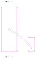
FIG. 1 is a schematic diagram of a fully automatic microorganism staining slide making device according to a preferred embodiment of the present invention;
fig. 2 is a dyeing tabletting flow chart of a full-automatic microorganism dyeing tabletting device provided by the invention;
FIG. 3 is a schematic view of the loading module shown in FIG. 1;
FIG. 4 is a schematic diagram of a droplet sorting module of FIG. 1;
FIG. 5 is a schematic diagram of the microscopic imaging control module of FIG. 1;
FIG. 6 is a schematic diagram of a configuration of the fluid control module shown in FIG. 1;
FIG. 7 is a schematic diagram of the first, second and third syringe pumps shown in FIG. 6;
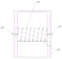
FIG. 8 is a schematic diagram of the heat sink shown in FIG. 7;
FIG. 9 is a side view of FIG. 8;
FIG. 10 is a cross-sectional view taken along A-A of FIG. 9;
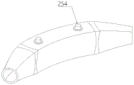
FIG. 11 is a schematic view of the spiral ring of FIG. 10;
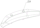
FIG. 12 is a schematic view of the baffle of FIG. 11;
FIG. 13 is a schematic view of the internal structure of the baffle;
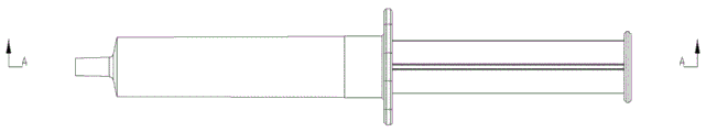
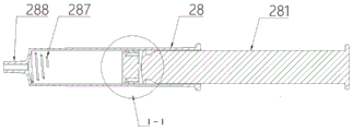
FIG. 14 is a schematic view of the injection matrix of FIG. 7;
FIG. 15 is a front view of the injection base;
FIG. 16 is a cross-sectional view taken along line A-A of FIG. 15;
FIG. 17 is an enlarged view of I-I of FIG. 16.
In the figure: 1. loading a module; 11. an electric stage; 12. a microfluidic chip; 121. a sample inlet; 122. a reagent inlet; 123. an oil phase inlet; 124. a liquid drop port; 125. a waste liquid outlet; 13. a waste liquid bottle; 14. a PC host; 2. a fluid control module; 21. a first syringe pump; 211. a liquid inlet pipe; 212. a liquid outlet pipe; 22. a second syringe pump; 23. a third syringe pump; 24. a bottom plate; 241. a fixed table; 25. a heat dissipation seat; 251. a concave table; 252. a spiral ring; 253. a flow guide; 254. a rubber pad; 255. a circulation pump; 256. a liquid inlet; 257. a liquid outlet; 26. a stepping motor; 261. a screw rod; 27. a pushing table; 28. injecting a matrix; 281. a push rod; 282. an upper sealing part; 283. a lower sealing part; 284. connecting convex balls; 285. a ring groove; 286. a diversion channel; 287. a cone spring; 288. a needle tube; 29. a box plate; 3. a reagent selection module; 31. a reagent table; 32. a sample solution tube; 33. an oil phase solution tube; 34. a reagent solution tube; 35. a six-position reversing valve; 36. detecting a connecting wire; 37. a liquid pressure sensor; 38. an electromagnetic valve; 4. a droplet sorting module; 41. sorting laser irradiators; 42. sipm silicon photomultiplier; 43. a charge ring; 44. a deflector plate; 5. a microscopic imaging control module; 51. a microscope; 52. an imaging laser illuminator; 53. an LED fluorescent light source; 54. a fluorescence camera; 55. a silicon photomultiplier; 56. a mirror assembly; 6. and a micro control module.
Detailed Description
The following description of the embodiments of the present invention will be made clearly and completely with reference to the accompanying drawings, in which it is apparent that the embodiments described are only some embodiments of the present invention, but not all embodiments. All other embodiments, which can be made by those skilled in the art based on the embodiments of the invention without making any inventive effort, are intended to be within the scope of the invention.
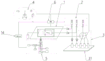
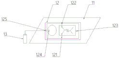
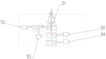
Referring to fig. 1 and 3, an embodiment of the present invention is provided: the full-automatic microorganism staining slide preparation device comprises a loading module 1, wherein an electric object stage 11 is arranged in the loading module 1, and a microfluidic chip 12 is loaded on the electric object stage 11; a fluid control module 2, the fluid control module 2 controlling the flow state of the sample in the microfluidic chip 12; the microfluidic chip 12 is provided with a sample inlet 121, a reagent inlet 122, an oil phase inlet 123, a liquid drop port 124 and a waste liquid outlet 125, and the waste liquid outlet 125 is connected with a waste liquid bottle 13 through a pipeline.
The full-automatic microorganism staining slide preparation device can realize automatic treatment of dilution, pyrolysis, staining, incubation, staining and the like on complex biological samples possibly containing microorganisms in the form of a microfluidic chip 12, so as to form a microorganism sample sheet which can be used for detection in a fluorescent or bright field environment, and realize full-process automatic quantitative detection of the microorganism content.
Specifically, the device comprises the following steps: the operations such as sample filtration, cell activation, cell marking, fluorescent scanning, microscope 51 detection and the like are integrated into one micro-fluidic chip 12 carrier, and the control of the liquid flow direction and the flow speed is realized by driving the fluid control module 2, so that the split-flow regulation and control of sample liquid, an activating agent and a coloring agent are realized, the automatic treatment of enrichment, activation and dyeing of the sample is realized under the totally-enclosed condition, the complicated manual operation of professional operators is avoided, the detection efficiency is improved, the secondary pollution possibility caused by the manual operation is also avoided, the waste of the sample is avoided, and the accuracy of the detection result is improved.
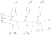
Referring to fig. 1, the fully automatic microorganism staining slide making device further comprises a reagent selecting module 3; the reagent selecting module 3 has a reagent table 31, and a sample solution tube 32, an oil phase solution tube 33, and a plurality of reagent solution tubes 34 are placed on the reagent table 31.
Referring to fig. 1 and 6, the reagent selecting module 3 has a six-position reversing valve 35, a plurality of reagent solution tubes 34 are connected with the six-position reversing valve 35, the six-position reversing valve 35 is connected with a liquid inlet tube 211 of the third syringe pump 23, a reagent inlet 122 is connected with a liquid outlet tube 212 of the third syringe pump 23, and the six-position reversing valve 35 is electrically connected with the micro-control module 6.
According to the full-automatic microbial staining flaking device, each injection pump can be controlled through the micro-control module 6, so that the addition amount, the addition speed and the addition pressure of the liquid in the corresponding sample solution tube 32, the oil phase solution tube 33 and the reagent solution tube 34 can be mixed and prepared in the microfluidic chip 12 through the sample inlet 121, the reagent inlet 122 and the oil phase inlet 123 under preset parameters, and the generation of target liquid drops is facilitated, and the flaking efficiency is improved; the micro control module 6 can also control the operations such as opening, closing, switching and the like of any valve port of the six-position reversing valve 35, so that reagent solution is extracted from a plurality of different reagent solution pipes 34 and sequentially injected into the micro-fluidic chip 12 through the reagent inlets 122, further, the reagent solution in the micro-fluidic chip 12 is added continuously, the reagent solution pipes 34 do not need to be replaced for a plurality of times, and the tabletting efficiency is improved.
Referring to fig. 1, 4 and 5, the fully automatic microorganism staining slide making device further comprises a droplet sorting module 4, a microscopic imaging control module 5 and a micro control module 6; the droplet sorting module 4 is integrated on the microfluidic chip 12, and the microscopic imaging control module 5 is used for collecting, storing and analyzing target images in the microfluidic chip 12, and the microscopic imaging control module 6 is electrically connected with the loading module 1, the fluid control module 2, the reagent selecting module 3, the droplet sorting module 4 and the microscopic imaging control module 5.
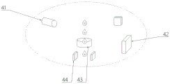
The droplet sorting module 4 has a sorting laser illuminator 41, a Sipm silicon photomultiplier 42, a charge ring 43 and a deflection plate 44 cooperatively disposed.
A PC host 14 is connected between the microscopic imaging control module 5 and the microscopic control module 6, the microscopic imaging control module 5 comprises a microscope 51, and an imaging laser irradiator 52, an LED fluorescent light source 53, a fluorescent camera 54, a silicon photomultiplier 55 and a reflecting mirror component 56 are arranged below the microscope 51 in a matched mode.
According to the full-automatic microbial staining film-making device, a PC host 14 is connected between an image processing module and a micro-control module 6, a specific wavelength laser is utilized to scan a micro-fluidic chip 12 line by line, a positive fluorescence position is found and calibrated, then a 400-1000X optical microscope 51 in a microscopic imaging control module 5 is used for carrying out microscopic examination on the positive fluorescence position, a digitized image of a bacterial morphological structure is rapidly obtained, and the photographed image is stored, recorded and analyzed in real time through the PC host 14, so that a real-time detection result is obtained, and a professional can observe and analyze data conveniently.
Referring to fig. 1 and 6, a first syringe pump 21, a second syringe pump 22 and a third syringe pump 23 are disposed in the fluid control module 2, the first syringe pump 21, the second syringe pump 22 and the third syringe pump 23 each have a liquid inlet tube 211 and a liquid outlet tube 212, the sample solution tube 32 is connected with the liquid inlet tube 211 of the first syringe pump 21, the sample inlet 121 is connected with the liquid outlet tube 212 of the first syringe pump 21, the oil phase solution tube 33 is connected with the liquid inlet tube 211 of the second syringe pump 22, and the oil phase inlet 123 is connected with the liquid outlet tube 212 of the second syringe pump 22.
Referring to fig. 1 and 6, the liquid outlet pipes 212 of the first, second and third syringe pumps 21, 22, 23 are electrically connected with a liquid pressure sensor 37 through a detection connection line 36, and electromagnetic valves 38 are respectively disposed on the liquid inlet pipe 211 and the liquid outlet pipe 212.
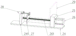
Referring to fig. 7, the first syringe pump 21, the second syringe pump 22, and the third syringe pump 23 each have a bottom plate 24, a heat dissipation seat 25 is disposed on the bottom plate 24, a stepper motor 26 is disposed on the heat dissipation seat 25, a screw rod 261 is connected to an output end of the stepper motor 26, a pushing table 27 is disposed on the screw rod 261, a fixing table 241 is disposed on the bottom plate 24, and an end portion of the screw rod 261 is pivotally connected to the fixing table 241.
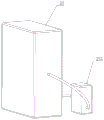
Referring to fig. 7 and 14-17, an injection substrate 28 is disposed on a fixing table 241, a push rod 281 is disposed on the injection substrate 28, one end of the push rod 281 is disposed inside the injection substrate 28, the other end of the push rod 281 is connected with the pushing table 27, one end of the push rod 281 is fixedly connected to the pushing table 27, an upper sealing portion 282 is disposed at the end of the push rod 281 located inside the injection substrate 28, a lower sealing portion 283 is disposed near the outlet end of the injection substrate 28, the upper sealing portion 282 and the lower sealing portion 283 are movably connected by a connecting convex ball 284, and the connecting convex ball 284 is a convex structure located at the center of the lower sealing portion 283.
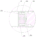
Referring to fig. 16 and 17, a plurality of ring grooves 285 are circumferentially formed in the side wall of the lower sealing portion 283, a flow guide channel 286 is formed in the lower sealing portion 283, the flow guide channel 286 is communicated with the ring grooves 285, a cone spring 287 is coaxially arranged at the inner bottom of the injection base 28, the cone portion of the cone spring 287 faces the lower sealing portion 283, and a needle tube 288 is arranged at one end of the injection base 28.
According to the full-automatic microorganism staining flaking device, through the design of the upper sealing part 282 and the lower sealing part 283, the stability and the sealing performance of the injection matrix 28 in the sucking process are enhanced, and the injection matrix 28 can be prevented from being broken due to overlarge local compression.
Specifically, the upper seal portion 282 and the lower seal portion 283 are preferably made of flexible materials such as rubber, and because the lower seal portion 283 is the first seal member in the injection matrix 28, and needs to continuously bear larger liquid pressure change relative to the upper seal portion 282, in order to obtain a stronger sealing effect, the seal members of this type are arranged in the injection matrix 28 to be long enough, so that larger friction resistance is generated between the seal members and the inner wall of the injection matrix 28, and the contact area between the lower seal portion 283 and the inner wall of the injection matrix 28 is reduced by the annular groove 285 arranged in the circumferential direction, so that noise or clamping problem caused by overlarge friction force between the lower seal portion 283 and the inner wall of the injection matrix 28 during suction action of the push rod 281 is avoided;
on the other hand, during the pumping action of the push rod 281, the lower sealing portion 283 is easy to deform, so that the liquid is easy to get close to one side of the liquid from the lower sealing portion 283, and due to the existence of the diversion channel 286 in the lower sealing portion 283 in the device, a certain accommodating space can be provided between the lower sealing portion 283 and the upper sealing portion 282, and the liquid flowing into the diversion channel 286 due to the deformation of the lower sealing portion 283 can be accommodated in the accommodating space or the accommodating space, so that the liquid is prevented from remaining on the inner side wall of the injection matrix 28, further, the tiny errors existing when reagent solution or sample solution is added are avoided, and the liquid is prevented from directly leaking onto the push rod 281 beyond the upper sealing portion 282 and the lower sealing portion 283, wherein the inlet end of the diversion channel 286 is close to the direction of the push rod 281, and the outlet end of the diversion channel 286 is communicated with the annular groove 285;
on the other hand, the liquid trapped in the accommodation space formed between the upper seal portion 282 and the lower seal portion 283 also prevents the entry of gas in the direction of the push rod 281, ensuring the sealing effect inside the injection base 28;
on the other hand, when the push rod 281 is in suction operation, part of the gas flows through the annular groove 285 and the diversion channel 286 to a certain extent in the accommodating space between the upper sealing part 282 and the lower sealing part 283, so that the problem of cracking of the side wall of the injection matrix 28 caused by excessive local pressure of the injection matrix 28 can be avoided;
on the other hand, through the arrangement of the cone spring 287, bubbles possibly existing in the liquid in the injection process are decomposed into small bubbles when passing through the cone spring 287, the influence on the dyeing tabletting effect and the microscopic examination effect is reduced, and meanwhile, the problem that the push rod 281 is easy to damage the injection matrix 28 due to excessive pushing of the screw rod is solved through the arrangement of the cone spring 287, wherein the cone spring 287 is located between the lower sealing portion 283 and the inner bottom surface of the injection matrix 28.
Referring to fig. 7-13, a concave table 251 is disposed in the heat dissipation seat 25, a spiral ring 252 is disposed on the concave table 251, the spiral ring 252 is connected end to end through a guiding member 253, the guiding member 253 has a tubular structure, the inner diameter of the guiding member 253 gradually increases from two ends to the middle, and a rubber pad 254 is disposed on the outer sidewall of the guiding member 253.
The full-automatic microorganism staining flaking device is used for ensuring a sterile environment, avoiding open operation, and is usually placed in a sterile box, while a power mechanism such as a stepping motor 26 is arranged outside the sterile box due to larger heat generation, but is close to the sterile box due to the limitation of a transmission structure, so that the generated heat is easily transferred into the sterile box, thereby influencing the temperature of staining flaking, and further influencing the accurate regulation and control of the micro environment for bacterial growth in a microfluidic chip 12 in the sample enrichment, activation and staining processes; the heat dissipation seat 25 in the device is arranged on the outer side wall of the aseptic box board 29, not only can be used for fixedly mounting the stepper motor 26, but also can be used for dissipating heat, specifically, the opposite side wall of the heat dissipation seat 25 is provided with a liquid inlet 256 and a liquid outlet 257, the liquid inlet 256 and the liquid outlet 257 are respectively communicated with two end parts of the spiral ring 252, and cooling liquid in the spiral ring 252 inside the heat dissipation seat is circulated through the circulating pump 255, so that the purpose of dissipating heat is achieved; when the cooling liquid flows through the internal cavity of the flow guiding member 253, the inner diameter of the cooling liquid gradually increases from two ends to the middle part, so that the spiral flow track of the cooling liquid is damaged, namely the flowing state and the flowing speed of the cooling liquid are damaged, the flowing time of the cooling liquid in the spiral ring 252 is prolonged, the heat exchange effect between the cooling liquid and the surrounding environment is improved, the concave table 251 can be used for collecting condensed water generated by the spiral ring 252, the arrangement of the elastic block can keep the structural form of the spiral ring 252, the deformation possibility of the elastic block is reduced, and the distance between the rings of the spiral ring 252 is ensured, so that the heat exchange effect is ensured.
Working principle:
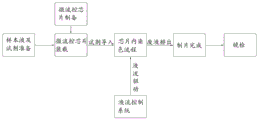
referring to fig. 1 and 2, the use of the fully automatic microorganism staining tabletting device specifically comprises the following steps:
s1: preparation of microfluidic chip 12: for the steps of the staining procedure, a microfluidic chip 12 satisfying the sample liquid and reagent input, waste liquid discharge, and microorganism capturing and enriching functions is prepared.
S2: assembly of automated fluid drive system: the sample liquid and the reagent are respectively packaged in an injection matrix 28 with specific specification, the injection matrix 28 is arranged in the fluid control module 2, and the liquid in the injection matrix 28 is pushed to be led out by the operation of an injection pump.
S3: assembly of an automated staining system: the sample inlet 121, the oil phase inlet 123, and the reagent inlet 122 of the microfluidic chip 12 are connected to the sample solution tube 32, the oil phase solution tube 33, and the reagent solution tube 34, respectively, and the waste liquid outlet 125 is connected to the waste liquid bottle 13.
S4: dyeing flow: and (3) operating corresponding injection pumps, sequentially driving sample liquid, reagent and oil phase liquid in the injection matrix 28 to be introduced into the microfluidic chip 12, realizing the mixing and dyeing reaction of the reagent and the sample liquid in the microfluidic chip 12, realizing the cleaning and discharging of the dyed reagent in the microfluidic chip 12 by the buffer solution, finally realizing the capturing and fixing of the dyed microorganisms in the microfluidic chip 12, closing the corresponding injection pumps, and completing the automatic tabletting.
S5: and (5) microscopic examination: and (5) conveying the micro-fluidic chip 12 with the successful preparation into a fluorescence and bright field environment for detection.
It will be evident to those skilled in the art that the invention is not limited to the details of the foregoing illustrative embodiments, and that the present invention may be embodied in other specific forms without departing from the spirit or essential characteristics thereof. The present embodiments are, therefore, to be considered in all respects as illustrative and not restrictive, the scope of the invention being indicated by the appended claims rather than by the foregoing description, and all changes which come within the meaning and range of equivalency of the claims are therefore intended to be embraced therein. Any reference sign in a claim should not be construed as limiting the claim concerned.
Claims (6)
1. A full-automatic microorganism staining flaking device, which comprises,
the device comprises a loading module (1), wherein an electric object stage (11) is arranged in the loading module (1), and a microfluidic chip (12) is loaded on the electric object stage (11);
a fluid control module (2), the fluid control module (2) controlling a sample flow state within the microfluidic chip (12);
the method is characterized in that: a sample inlet (121), a reagent inlet (122), an oil phase inlet (123), a liquid dropping port (124) and a waste liquid outlet (125) are formed in the microfluidic chip (12), and the waste liquid outlet (125) is connected with a waste liquid bottle (13) through a pipeline;
the full-automatic microorganism staining flaking device further comprises a reagent selection module (3), wherein a reagent table (31) is arranged in the reagent selection module (3), and a sample solution tube (32), an oil phase solution tube (33) and a plurality of reagent solution tubes (34) are arranged on the reagent table (31);
the full-automatic microorganism staining film-making device further comprises a liquid drop sorting module (4), a microscopic imaging control module (5) and a micro control module (6), wherein the liquid drop sorting module (4) is integrated on the microfluidic chip (12), the microscopic imaging control module (5) is used for collecting, storing and analyzing data of target images in the microfluidic chip (12), and the micro control module (6) is electrically connected with the loading module (1), the fluid control module (2), the reagent selection module (3), the liquid drop sorting module (4) and the microscopic imaging control module (5);
a first injection pump (21), a second injection pump (22) and a third injection pump (23) are arranged in the fluid control module (2);
the first injection pump (21), the second injection pump (22) and the third injection pump (23) are respectively provided with a bottom plate (24), a radiating seat (25) is arranged on the bottom plate (24), a stepping motor (26) is arranged on the radiating seat (25), a screw rod (261) is connected to the output end of the stepping motor (26), a pushing table (27) is arranged on the screw rod (261), and a fixing table (241) is arranged on the bottom plate (24);
an injection substrate (28) is arranged on the fixed table (241), a push rod (281) is arranged on the injection substrate (28), one end part of the push rod (281) is arranged in the injection substrate (28), the other end part of the push rod (281) is fixedly connected with the pushing table (27), an upper sealing part (282) is arranged at the end part of the push rod (281) positioned in the injection substrate (28), a lower sealing part (283) is arranged near the outlet end of the injection substrate (28), and the upper sealing part (282) and the lower sealing part (283) are movably connected through a connecting convex ball (284);
a plurality of annular grooves (285) are formed in the circumferential direction of the side wall of the lower sealing part (283), a flow guide channel (286) is formed in the lower sealing part (283), the flow guide channel (286) is communicated with the annular grooves (285), a conical spring (287) is coaxially arranged at the inner bottom of the injection matrix (28), the conical part of the conical spring (287) faces the lower sealing part (283), and a needle tube (288) is arranged at one end part of the injection matrix (28);
the annular groove (285) formed in the circumferential direction of the lower sealing part (283) reduces the contact area between the lower sealing part (283) and the inner side wall of the injection matrix (28), and noise or blocking caused by overlarge friction force between the lower sealing part (283) and the inner side wall of the injection matrix (28) during the suction action of the push rod (281) is avoided;
the inside concave station (251) that is equipped with of heat dissipation seat (25), be equipped with spiral ring (252) on concave station (251), spiral ring (252) are through water conservancy diversion spare (253) end to end, and water conservancy diversion spare (253) have tubular structure, and the internal diameter of water conservancy diversion spare (253) is from both ends to middle part increase gradually, is equipped with rubber pad (254) on the lateral wall of water conservancy diversion spare (253).
2. The fully automatic microbial staining slide making apparatus of claim 1 wherein: the first injection pump (21), the second injection pump (22) and the third injection pump (23) are respectively provided with a liquid inlet pipe (211) and a liquid outlet pipe (212), the sample solution pipe (32) is connected with the liquid inlet pipe (211) of the first injection pump (21), the sample inlet (121) is connected with the liquid outlet pipe (212) of the first injection pump (21), the oil phase solution pipe (33) is connected with the liquid inlet pipe (211) of the second injection pump (22), and the oil phase inlet (123) is connected with the liquid outlet pipe (212) of the second injection pump (22).
3. A fully automated microbial staining slide processing apparatus according to claim 2 wherein: the reagent selection module (3) is provided with six-position reversing valves (35), a plurality of reagent solution pipes (34) are connected with the six-position reversing valves (35), the six-position reversing valves (35) are connected with a liquid inlet pipe (211) of the third injection pump (23), a reagent inlet (122) is connected with a liquid outlet pipe (212) of the third injection pump (23), and the six-position reversing valves (35) are electrically connected with the micro control module (6).
4. A fully automated microbial staining slide processing apparatus according to claim 3 wherein: liquid pressure sensors (37) are electrically connected between liquid outlet pipes (212) of the first injection pump (21), the second injection pump (22) and the third injection pump (23) through detection connecting wires (36), and electromagnetic valves (38) are arranged on the liquid inlet pipes (211) and the liquid outlet pipes (212).
5. The fully automatic microbial staining slide making apparatus of claim 4 wherein: one end of the screw rod (261) is connected with the fixed table (241) in a shaft way.
6. The method for using a fully automatic microbial staining slide preparation device according to claim 1, comprising the following steps: the preparation of the micro-fluidic chip (12), the assembly of an automatic liquid flow driving system, the assembly of an automatic dyeing system, the dyeing flow and the microscopic examination.
Applications Claiming Priority (2)
| Application Number | Priority Date | Filing Date | Title |
|---|---|---|---|
| CN202211672269 | 2022-12-26 | ||
| CN2022116722695 | 2022-12-26 |
Publications (2)
| Publication Number | Publication Date |
|---|---|
| CN115962995A CN115962995A (en) | 2023-04-14 |
| CN115962995B true CN115962995B (en) | 2023-07-04 |
Family
ID=85888207
Family Applications (1)
| Application Number | Title | Priority Date | Filing Date |
|---|---|---|---|
| CN202310251615.0A Active CN115962995B (en) | 2022-12-26 | 2023-03-16 | Full-automatic microorganism dyeing film-making device |
Country Status (1)
| Country | Link |
|---|---|
| CN (1) | CN115962995B (en) |
Citations (3)
| Publication number | Priority date | Publication date | Assignee | Title |
|---|---|---|---|---|
| CN203493977U (en) * | 2013-08-12 | 2014-03-26 | 山东新华安得医疗用品有限公司 | Injector for flushing catheter |
| CN108020490A (en) * | 2017-06-23 | 2018-05-11 | 中国科学院天津工业生物技术研究所 | A kind of high flux screening equipment using drop micro-fluidic chip |
| JP2019217105A (en) * | 2018-06-21 | 2019-12-26 | 株式会社松風 | Injector |
Family Cites Families (12)
| Publication number | Priority date | Publication date | Assignee | Title |
|---|---|---|---|---|
| JP4842796B2 (en) * | 2006-12-26 | 2011-12-21 | 株式会社日立エンジニアリング・アンド・サービス | Microorganism testing apparatus and microbe testing measuring chip |
| AU2013216878B2 (en) * | 2012-02-09 | 2016-09-29 | Beckman Coulter, Inc. | Sorting flow cytometer |
| IL227276A0 (en) * | 2013-07-01 | 2014-03-06 | Parasight Ltd | A method and system for preparing a monolayer of cells, particularly suitable for diagnosis |
| WO2016149639A1 (en) * | 2015-03-19 | 2016-09-22 | The Board Of Trustees Of The Leland Stanford Junior University | Devices and methods for high-throughput single cell and biomolecule analysis and retrieval in a microfluidic chip |
| CN104745452B (en) * | 2015-04-20 | 2017-06-16 | 南京康芯微健康科技有限公司 | Rare cell automates capture device |
| US11446671B2 (en) * | 2016-03-29 | 2022-09-20 | Leica Microsystems Cms Gmbh | Self-contained slide processing unit for biological specimens |
| CN205698713U (en) * | 2016-04-19 | 2016-11-23 | 江苏紫金东方超声电机有限公司 | A kind of with ultrasound electric machine be drive syringe pump without magnetic |
| CN107167416B (en) * | 2017-05-15 | 2023-07-07 | 中国科学院微生物研究所 | Sorting type flow cytometer |
| CN107096099B (en) * | 2017-06-02 | 2024-01-02 | 雷诺丽特恒迅包装科技(北京)有限公司 | Propelling device |
| CN109916803A (en) * | 2019-02-27 | 2019-06-21 | 苏州朗如精密机械科技有限公司 | A kind of stream type cell analyzer sample sorting detection module and its automatically sort detection method |
| CN112986063B (en) * | 2021-01-18 | 2022-04-15 | 西北大学 | High-throughput chromosome and cytoskeleton strain flow analyzer and implementation method |
| CN215134909U (en) * | 2021-03-05 | 2021-12-14 | 喻晓 | Quantitative injector |
-
2023
- 2023-03-16 CN CN202310251615.0A patent/CN115962995B/en active Active
Patent Citations (3)
| Publication number | Priority date | Publication date | Assignee | Title |
|---|---|---|---|---|
| CN203493977U (en) * | 2013-08-12 | 2014-03-26 | 山东新华安得医疗用品有限公司 | Injector for flushing catheter |
| CN108020490A (en) * | 2017-06-23 | 2018-05-11 | 中国科学院天津工业生物技术研究所 | A kind of high flux screening equipment using drop micro-fluidic chip |
| JP2019217105A (en) * | 2018-06-21 | 2019-12-26 | 株式会社松風 | Injector |
Non-Patent Citations (1)
| Title |
|---|
| 基于微流控芯片的单细胞图像观测系统的设计;孙惠芹等;传感技术学报;21(12);第1977-1980页 * |
Also Published As
| Publication number | Publication date |
|---|---|
| CN115962995A (en) | 2023-04-14 |
Similar Documents
| Publication | Publication Date | Title |
|---|---|---|
| JP6751382B2 (en) | Automated system and method for preparing biological samples for testing | |
| US7276720B2 (en) | Apparatus and methods for analyzing samples | |
| JPH0280937A (en) | Flow cell device | |
| US20060012793A1 (en) | Apparatus and methods for analyzing samples | |
| CN108641902A (en) | Hybridization instrument and molecular detection system | |
| EP3921687B1 (en) | Liquid immersion microscope objective assembly and related systems and methods | |
| JP2016519770A (en) | Automated system and method for preparing biological samples for testing | |
| CN208485868U (en) | Hybridization instrument and molecular detection system | |
| CN115962995B (en) | Full-automatic microorganism dyeing film-making device | |
| WO2017141362A1 (en) | Analysis apparatus | |
| CN112748254A (en) | Medium system for sample detection equipment | |
| JP5118573B2 (en) | Object processing equipment | |
| CN108254235A (en) | Array sample injector | |
| CN218573721U (en) | Wash smart art liquid-transfering system | |
| EP4152074A1 (en) | Microscope system and method for imaging a sample involving injecting multiple temporally spaced microjets | |
| TWM644324U (en) | Cell detecting system | |
| JP2005291729A (en) | Biochemical analyzer |
Legal Events
| Date | Code | Title | Description |
|---|---|---|---|
| PB01 | Publication | ||
| PB01 | Publication | ||
| SE01 | Entry into force of request for substantive examination | ||
| SE01 | Entry into force of request for substantive examination | ||
| GR01 | Patent grant | ||
| GR01 | Patent grant |