EP3586894B1 - Injector - Google Patents
Injector Download PDFInfo
- Publication number
- EP3586894B1 EP3586894B1 EP19181122.3A EP19181122A EP3586894B1 EP 3586894 B1 EP3586894 B1 EP 3586894B1 EP 19181122 A EP19181122 A EP 19181122A EP 3586894 B1 EP3586894 B1 EP 3586894B1
- Authority
- EP
- European Patent Office
- Prior art keywords
- barrel
- plunger
- injector
- movable body
- stopper
- Prior art date
- Legal status (The legal status is an assumption and is not a legal conclusion. Google has not performed a legal analysis and makes no representation as to the accuracy of the status listed.)
- Active
Links
Images






Classifications
-
- A—HUMAN NECESSITIES
- A61—MEDICAL OR VETERINARY SCIENCE; HYGIENE
- A61M—DEVICES FOR INTRODUCING MEDIA INTO, OR ONTO, THE BODY; DEVICES FOR TRANSDUCING BODY MEDIA OR FOR TAKING MEDIA FROM THE BODY; DEVICES FOR PRODUCING OR ENDING SLEEP OR STUPOR
- A61M5/00—Devices for bringing media into the body in a subcutaneous, intra-vascular or intramuscular way; Accessories therefor, e.g. filling or cleaning devices, arm-rests
- A61M5/178—Syringes
- A61M5/31—Details
- A61M5/3129—Syringe barrels
- A61M5/3135—Syringe barrels characterised by constructional features of the proximal end
-
- B—PERFORMING OPERATIONS; TRANSPORTING
- B65—CONVEYING; PACKING; STORING; HANDLING THIN OR FILAMENTARY MATERIAL
- B65D—CONTAINERS FOR STORAGE OR TRANSPORT OF ARTICLES OR MATERIALS, e.g. BAGS, BARRELS, BOTTLES, BOXES, CANS, CARTONS, CRATES, DRUMS, JARS, TANKS, HOPPERS, FORWARDING CONTAINERS; ACCESSORIES, CLOSURES, OR FITTINGS THEREFOR; PACKAGING ELEMENTS; PACKAGES
- B65D83/00—Containers or packages with special means for dispensing contents
- B65D83/76—Containers or packages with special means for dispensing contents for dispensing fluent contents by means of a piston
-
- A—HUMAN NECESSITIES
- A61—MEDICAL OR VETERINARY SCIENCE; HYGIENE
- A61C—DENTISTRY; APPARATUS OR METHODS FOR ORAL OR DENTAL HYGIENE
- A61C5/00—Filling or capping teeth
-
- A—HUMAN NECESSITIES
- A61—MEDICAL OR VETERINARY SCIENCE; HYGIENE
- A61M—DEVICES FOR INTRODUCING MEDIA INTO, OR ONTO, THE BODY; DEVICES FOR TRANSDUCING BODY MEDIA OR FOR TAKING MEDIA FROM THE BODY; DEVICES FOR PRODUCING OR ENDING SLEEP OR STUPOR
- A61M5/00—Devices for bringing media into the body in a subcutaneous, intra-vascular or intramuscular way; Accessories therefor, e.g. filling or cleaning devices, arm-rests
- A61M5/178—Syringes
-
- A—HUMAN NECESSITIES
- A61—MEDICAL OR VETERINARY SCIENCE; HYGIENE
- A61M—DEVICES FOR INTRODUCING MEDIA INTO, OR ONTO, THE BODY; DEVICES FOR TRANSDUCING BODY MEDIA OR FOR TAKING MEDIA FROM THE BODY; DEVICES FOR PRODUCING OR ENDING SLEEP OR STUPOR
- A61M5/00—Devices for bringing media into the body in a subcutaneous, intra-vascular or intramuscular way; Accessories therefor, e.g. filling or cleaning devices, arm-rests
- A61M5/178—Syringes
- A61M5/31—Details
-
- A—HUMAN NECESSITIES
- A61—MEDICAL OR VETERINARY SCIENCE; HYGIENE
- A61M—DEVICES FOR INTRODUCING MEDIA INTO, OR ONTO, THE BODY; DEVICES FOR TRANSDUCING BODY MEDIA OR FOR TAKING MEDIA FROM THE BODY; DEVICES FOR PRODUCING OR ENDING SLEEP OR STUPOR
- A61M5/00—Devices for bringing media into the body in a subcutaneous, intra-vascular or intramuscular way; Accessories therefor, e.g. filling or cleaning devices, arm-rests
- A61M5/178—Syringes
- A61M5/31—Details
- A61M5/3129—Syringe barrels
- A61M2005/3131—Syringe barrels specially adapted for improving sealing or sliding
-
- A—HUMAN NECESSITIES
- A61—MEDICAL OR VETERINARY SCIENCE; HYGIENE
- A61M—DEVICES FOR INTRODUCING MEDIA INTO, OR ONTO, THE BODY; DEVICES FOR TRANSDUCING BODY MEDIA OR FOR TAKING MEDIA FROM THE BODY; DEVICES FOR PRODUCING OR ENDING SLEEP OR STUPOR
- A61M5/00—Devices for bringing media into the body in a subcutaneous, intra-vascular or intramuscular way; Accessories therefor, e.g. filling or cleaning devices, arm-rests
- A61M5/178—Syringes
- A61M5/31—Details
- A61M5/3129—Syringe barrels
- A61M5/3137—Specially designed finger grip means, e.g. for easy manipulation of the syringe rod
- A61M2005/3139—Finger grips not integrally formed with the syringe barrel, e.g. using adapter with finger grips
-
- A—HUMAN NECESSITIES
- A61—MEDICAL OR VETERINARY SCIENCE; HYGIENE
- A61M—DEVICES FOR INTRODUCING MEDIA INTO, OR ONTO, THE BODY; DEVICES FOR TRANSDUCING BODY MEDIA OR FOR TAKING MEDIA FROM THE BODY; DEVICES FOR PRODUCING OR ENDING SLEEP OR STUPOR
- A61M5/00—Devices for bringing media into the body in a subcutaneous, intra-vascular or intramuscular way; Accessories therefor, e.g. filling or cleaning devices, arm-rests
- A61M5/178—Syringes
- A61M5/31—Details
- A61M5/315—Pistons; Piston-rods; Guiding, blocking or restricting the movement of the rod or piston; Appliances on the rod for facilitating dosing ; Dosing mechanisms
- A61M5/31501—Means for blocking or restricting the movement of the rod or piston
- A61M5/31505—Integral with the syringe barrel, i.e. connected to the barrel so as to make up a single complete piece or unit
- A61M2005/31506—Integral with the syringe barrel, i.e. connected to the barrel so as to make up a single complete piece or unit formed as a single piece, e.g. moulded
-
- A—HUMAN NECESSITIES
- A61—MEDICAL OR VETERINARY SCIENCE; HYGIENE
- A61M—DEVICES FOR INTRODUCING MEDIA INTO, OR ONTO, THE BODY; DEVICES FOR TRANSDUCING BODY MEDIA OR FOR TAKING MEDIA FROM THE BODY; DEVICES FOR PRODUCING OR ENDING SLEEP OR STUPOR
- A61M5/00—Devices for bringing media into the body in a subcutaneous, intra-vascular or intramuscular way; Accessories therefor, e.g. filling or cleaning devices, arm-rests
- A61M5/178—Syringes
- A61M5/31—Details
- A61M5/315—Pistons; Piston-rods; Guiding, blocking or restricting the movement of the rod or piston; Appliances on the rod for facilitating dosing ; Dosing mechanisms
- A61M5/31501—Means for blocking or restricting the movement of the rod or piston
- A61M2005/31508—Means for blocking or restricting the movement of the rod or piston provided on the piston-rod
Definitions
- the present invention relates to an injector.
- An injector is conventionally known that has a configuration in which a plunger for pushing and moving a seal body toward a discharge port of a barrel is prevented from coming off from the barrel.
- the barrel includes a convex portion projecting from an inner circumferential surface thereof, and the plunger includes a locking portion locked to the convex portion.
- Patent Document 2 discloses a syringe assembly including a syringe barrel having an interior surface and a substantially closed discharge end defining a discharge opening.
- a stop is mounted on the interior surface of the syringe barrel.
- a piston is slidably disposed within the syringe barrel.
- the piston has a forward-most sealing surface and the rearward-most sealing surface.
- the piston is movable between a first position and a second position.
- a plunger rod has a finger extending therefrom, the finger having a distal end portion constructed to engage the stop when the piston is in its second position.
- Patent Document 3 discloses a prefilled syringe comprising a barrel having a closed front-end wall with a small passageway through which injection liquid is discharged and a rear opening, a plunger including a sliding plug liquid tightly contacting with the inner surface of the barrel and partitioning the inside of the barrel into a liquid-filled area which is formed between said plunger and said closed front-end wall and in which the injection liquid is filled and sealed, and a liquid-unfilled area in the back of the liquid-filled area and a plunger rod extending backward from said sliding plug through said rear opening of the barrel, and a plunger withdrawal-limiting member in the form of a flange fixed to the rear opening of said barrel and extending inwardly in the radial direction from the periphery of the rear opening of said barrel, which limits plunger withdrawal by engaging said plunger, wherein, said plunger withdrawal-limiting member has an opening sized to allow said plunger rod to pass therethrough, and said plunger rod has a stopper member extending outwardly in the radi
- Patent Document 4 discloses a syringe for medical applications including a syringe body having an inner wall, a first stop, located along the inner wall, to leave at least one first blank surface on the inner wall, and a plunger sliding along the inner wall of a longitudinal axis of the syringe, the plunger including a plunger head and an operating rod, connected to the plunger head, including, on its outer surface, at least one first rack arranged longitudinally along the operating rod, the first rack including protruding teeth.
- the first stop and the protruding teeth are shaped and constituted so as to prevent the plunger from lowering again due to pressure on the operating rod, unless the first rack is disengaged by rotating the plunger within the syringe body around the longitudinal axis so that the first rack faces the first blank surface of the inner wall of the syringe body.
- Patent Document 5 discloses a syringe-type ejector that includes a syringe and a plunger, the plunger including a first shaft member having a piston at its tip, and a second shaft member that fits with a tube portion of the first shaft member.
- the first shaft member has an elastic piece that extends rearward, the elastic piece being provided with a sliding projection that is slidable along an inner circumferential surface of the syringe and a locking projection that locks to a rear end of the syringe.
- the second shaft member has a pressing axis that fits with the tube portion, the pressing axis being provided at the tip, with an end surface that presses a free end of the elastic piece, and being provided, on an outer circumferential surface, with an engaging projection that engages with a locking portion of the tube portion to prevent removal from the tube portion.
- the locking projection is locked to the rear end of the syringe by the pressing force from the end surface and the locking of the locking projection is released by relieving the pressing force.
- the seal body climbs over the convex portion projecting from the inner circumferential surface of the barrel before being housed into the barrel. In this case, the seal body may be damaged due to contact with the convex portion.
- the present invention provides an injector as defined in appended claim 1.
- the seal body can be housed into the barrel without damage and the plunger can be prevented from falling off from the barrel in the injector.
- An injector comprises a cylindrical barrel including a discharge port, a seal body coming into close contact with an inner circumferential surface of the barrel, a plunger for pushing and moving the seal body to the discharge port side of the barrel, and a stopper disposed on one of the barrel and the plunger and coming into elastic contact with the other in a radial direction of the barrel. Further, the seal body and the plunger are configured to separate from each other by retracting the plunger.
- the seal body can be housed into the barrel without damage and the plunger can be prevented from falling off from the barrel in the injector.
- the stopper may be a plate spring-shaped member including a fixed end attached to the plunger and a free end coming into elastic contact with the inner circumferential surface of the barrel.
- the free end may be located on the base end side of the barrel with respect to the fixed end.
- the free end may be located on the leading end side of the barrel with respect to the fixed end.
- the inner circumferential surface of the barrel may be provided with a circumferential groove with which the free end of the stopper is engaged. Since the free end of the stopper engages with the circumferential groove, the plunger is prevented from coming off from the barrel.
- the circumferential groove may have a slope surface extending from a bottom potion of the circumferential groove toward the leading end of the barrel and sloping with respect to the inner circumferential surface.
- the stopper may be a plate spring-shaped member including a fixed end attached to the barrel and a free end coming into elastic contact with the plunger.
- the barrel may have two slits formed to extend from a base end thereof, and wherein the stopper may be made up of a portion of the barrel interposed between the two slits.
- Fig. 1 is an external view of an injector according to a first embodiment of the present invention
- Fig. 2 is a partial cross-sectional view of the injector.
- an injector 10 includes a barrel 12 containing, for example, a pasty fluid, a movable body 14 movably housed in the barrel 12, and a plunger 16 for pushing and moving the movable body 14.
- the injector 10 also has a nozzle tip 18 attached to a leading end 12a of the barrel 12 and a finger grip 20 rotatably fitted to a base end 12b of the barrel 12.
- Fig. 3 is a cross-sectional view of the barrel
- Fig. 4 is an enlarged cross-sectional view of the barrel shown in Fig. 3 .
- the barrel 12 is a cylindrical member having a central axis C1, and is made of a resin material, for example.
- the barrel 12 includes a discharge port 12c at the leading end 12a and a flange portion 12d at the base end 12b.
- the discharge port 12c is connected to a nozzle inside flow passage communicating with the outside in the nozzle tip 18.
- the flange portion 12d functions as a stopper preventing the finger grip 20 rotatably fitted to a base end side portion of the barrel 12 from falling off.
- a circumferential groove 12f is formed in a base end side portion of an inner circumferential surface 12e of the barrel 12. The reason why the circumferential groove 12f is formed will be described later.
- Fig. 5 is a perspective view of the movable body
- Fig. 6 is a partial cross-sectional view of the movable body.
- the movable body 14 is a substantially cylindrical member having a central axis C2.
- the movable body 14 is made of an elastically deformable resin material, for example.
- the movable body 14 is made of a material easily elastically deformed as compared to the barrel 12.
- the movable body 14 includes a main body 14a, a seal body 14b disposed on the main body 14a, and a flange 14c disposed on the main body 14a.
- the main body 14a of the movable body 14 is cylindrical and has an outer diameter d2 smaller than an inner diameter d1 of the barrel 12 shown in Fig. 4 . Therefore, while the movable body 14 is housed in the barrel 12, a clearance is generated between the main body 14a and the inner circumferential surface 12e of the barrel 12.
- the seal body 14b of the movable body 14 has a disk shape and has an outer circumferential end brought into close contact with the inner circumferential surface 12e of the barrel 12 in a slidable and fluid-tight manner.
- the seal body 14b and the main body 14a are integrated as one part, the seal body 14b and the main body 14a may be separate parts.
- the seal body 14b For close contact of the outer circumferential end with the inner circumferential surface 12e of the barrel 12 in a fluid-tight manner, the seal body 14b has an outer diameter d3 larger than the inner diameter d1 of the barrel 12.
- the outer diameter d3 of the seal body 14b is larger than the outer diameter d2 of the main body 14a of the movable body 14.
- the seal body 14b has a central portion attached to a front end of the main body 14a (the end closer to the leading end 12a of the barrel 12). Additionally, an outer circumferential side portion of the seal body 14b is away from the main body 14a when the portion is in a free state (when the movable body 14 is present outside the barrel 12).
- the flange 14c of the movable body 14 is a projecting portion projecting from the main body toward the inner circumferential surface of the barrel 12 and is disposed at a rear end of the main body 14a (the end closer to the base end 12b of the barrel 12).
- the flange 14c has an outer diameter d4 smaller than the outer diameter d3 of the seal body 14b.
- the outer diameter d4 of the flange 14c is smaller than the inner diameter d1 of the barrel 12 and larger than the outer diameter d2 of the main body 14a.
- the movable body 14 also includes a planar-shaped rear end surface 14d orthogonal to the central axis C2 and includes a non-penetrating hole-shaped guide hole 14e in the rear end surface 14d.
- Fig. 7 is an external view of the plunger.
- the plunger 16 is a member for pushing and moving the movable body 14 housed in the barrel 12 toward the leading end 12a (i.e., the discharge port 12c) of the barrel 12, has a central axis C3, and is made of a resin material, for example.
- the plunger 16 is configured to come into separable contact with the movable body 14.
- the plunger 16 includes a contact portion 16a coming into contact with the movable body 14 on the front end side (the side closer to the leading end 12a of the barrel 12).
- the contact portion 16a has an outer diameter d5 smaller than the inner diameter d1 of the barrel 12.
- the contact portion 16a includes a planar-shaped contact surface 16b coming into surface contact with the planar-shaped rear end surface 14d of the movable body 14.
- the plunger 16 includes a guide pin 16c projecting from the contact surface 16b of the contact portion 16a. While the rear end surface 14d of the movable body 14 is in surface contact with the contact surface 16b of the plunger 16, the guide pin 16c is received in the guide hole 14e of the movable body 14.
- An outer diameter d6 of the guide pin 16c is smaller than an inner diameter d7 of the guide hole 14e shown in Fig. 6 so that the guide pin is received in the guide hole 14e of the movable body 14 in a manner enabling forward and backward movement. Since the guide pin 16c is guided by the guide hole 14e, the contact surface 16b of the plunger 16 can appropriately come into surface contact with the rear end surface 14d of the movable body 14.
- the movable body 14 and the plunger 16 can come into contact with each other in a state in which the central axis C2 of the movable body 14 and the central axis C3 of the plunger 16 are arranged substantially on the same straight line.
- the plunger 16 can push and move the movable body 14 toward the leading end 12a of the barrel 12 without tilting.
- the movable body 14 can be pushed and moved toward the leading end 12a of the barrel 12 by advancing the plunger 16. Additionally, the movable body 14 and the plunger 16 can be separated from each other by simply retracting the plunger 16.
- the plunger 16 Since the plunger 16 is not fixed to the movable body 14 while the seal body 14b is in close contact with the inner circumferential surface 12e of the barrel 12, the plunger 16 possibly comes off from the barrel 12. For example, if the injector 10 is in a state with the nozzle tip 18 located downward and a user grasps only the plunger 16 to lift the injector 10, the barrel 12 may fall off from the plunger 16 due to its own weight.
- the two stoppers 16d are arranged oppositely to each other across the central axis C3 of the plunger 16, so that the central axis C3 of the plunger 16 can be aligned with the central axis C1 of the barrel 12.
- the movable body 14 is pushed and moved toward the leading end 12a of the barrel 12 by the plunger 16.
- the seal body 14b is elastically deformed. Specifically, due to the friction force generated between the outer circumferential end of the seal body 14b and the inner circumferential surface 12e of the barrel 12, the seal body 14b is elastically deformed such that the outer circumferential side portion of the seal body 14b approaches the main body 14a. The seal body 14b moves in this elastically deformed state and pushes and moves the fluid F toward the discharge port 12c.
- the seal body 14b is returned (restored) to the original shape with the outer circumferential side portion separated from the main body 14a.
- the movable body 14 entirely retracts toward the base end of the barrel 12 without changing the contact position on the inner circumferential surface 12e of the barrel 12 in contact with the outer circumferential end of the seal body 14b.
- the fluid F in the nozzle tip 18 is drawn toward the seal body 14b, and the subsequent dripping of the fluid F is suppressed.
- the movable body 14 retracts through the restoration of the seal body 14b without changing the position of contact of the seal body 14b with the barrel 12 as described above, the flange 14c is moved along the inner circumferential surface 12e of the barrel 12. As a result, the movable body 14 can retreat in the extending direction of the central axis C1 of the barrel 12. If the flange 14c does not exit, the movable body 14 retracts in a direction tilted with respect to the central axis C1 of the barrel 12, so that the movable body 14 may have a posture in which a portion of an outer edge of the rear end surface 14d comes into contact with the inner circumferential surface 12e of the barrel 12, i.e., a tilted posture. If the movable body 14 is tilted, the adhesion between the seal body 14b and the inner circumferential surface 12e of the barrel 12 is partially weakened, so that the fluid F may leak to the base end side of the barrel 12.
- the outer diameter d4 of the flange 14c of the movable body 14 is smaller than the inner diameter d1 of the barrel 12. Therefore, the flange 14c can be moved without strong contact with the inner circumferential surface 12e of the barrel 12, i.e., in a state of substantially zero friction force.
- the outer diameter d4 of the flange 14c of the movable body 14 may be equal to or larger than the inner diameter d1 of the barrel 12.
- the friction force between the flange 14c and the barrel 12 must be smaller than the friction force between the seal body 14b and the barrel 12. Otherwise, the restoration of the seal body 14b and the retraction of the movable body 14 due to the restoration cannot be achieved.
- the distance L2 between the seal body 14b and the flange 14c in the movable body 14 is made larger than the outer diameter d3 of the seal body 14b. Therefore, when the movable body 14 retracts due to the restoration of the seal body 14b, the movable body 14 is hardly tilted (as compared to when the distance L2 is smaller than the outer diameter d3).
- the plunger 16 separated from the movable body 14 is kept housed in the barrel 12 by the stoppers 16d without coming off from the barrel 12.
- the plunger 16 during retraction toward the base end of the barrel 12 due to pulling by the user is restrained by engagement of the free ends 16f of the stoppers 16d with the circumferential groove 12f. As a result, the plunger 16 is prevented from coming off from the barrel 12.
- the seal body can be housed into the barrel without damage and the plunger can be prevented from falling off from the barrel in the injector.
- Fig. 9 is an enlarged cross-sectional view of a leading end side portion of a barrel in an injector according to the second embodiment.
- Fig. 10 is an enlarged cross-sectional view of a base end side portion of the barrel.
- a plunger 116 includes stoppers 116d.
- Each of the stoppers 116d is a plate spring-shaped member including a fixed end 116e attached to the plunger 116 and a free end 116f elastically contacting the inner circumferential surface 12e of the barrel 12.
- the free end 116f of the stopper 116d is located on the leading end side of the barrel 12 with respect to the fixed end 116e. Therefore, a contact surface 116b of the plunger 116 coming into contact with the rear end surface 14d of the movable body 14 is closer to the free end 116f of the stopper 116d as compared to the first embodiment shown in Fig. 8D .
- the seal body can be housed into the barrel without damage and the plunger can be prevented from falling off from the barrel in the injector.
- the stoppers preventing the plunger from coming off from the barrel are disposed on the plunger.
- stoppers are disposed on the barrel. Therefore, the third embodiment will be described mainly in terms of the different stoppers.
- the same reference numerals are given to constituent elements in the third embodiment that are substantially the same as the constituent elements in the first embodiment described above.
- Fig. 11 is a partial cross-sectional view of an injector according to the third embodiment.
- Fig. 12 is a cross-sectional view of the injector taken along a line A-A shown in Fig. 11 .
- Fig. 13 is an enlarged cross-sectional view of a barrel, showing stoppers when the movable body is housed into the barrel. In Fig. 11 , the nozzle tip and the finger grip are not shown.
- no stopper is disposed on a plunger 216.
- a pair of stoppers 212f facing each other is disposed on a barrel 212.
- the stoppers 212f are made up of portions of the barrel 212 each interposed between two slits 212g formed to extend from a base end 212b of the barrel 212.
- a portion of the barrel 212 interposed between base portions of the two slits 212g is defined as a fixed end 212h of the stopper 212f.
- a claw 212j brought into elastic contact with the plunger 216 is disposed on the inner side of a free end 212i of each of the paired stoppers 212f.
- the stopper 212f is a plate spring-shaped member (a plate spring-shaped member integrated with the barrel 212) having the fixed end 212h attached to the barrel 212 and the free end 212i brought into elastic contact with the plunger 216 (via the claws 212j).
- a distance between the claws 212j of the pair of the stoppers 212f is made smaller than an outer diameter of a shaft portion 216b of the plunger 216.
- the pair of the claws 212j holds the shaft portion 216b of the plunger 216. Consequently, the plunger 216 is prevented from coming off from the barrel 212.
- the plunger 216 during retraction toward the base end 212b of the barrel 212 due to pulling by the user is restrained when a contact portion 216a for contact with the movable body 14 is brought into contact with the claws 212j. As a result, the plunger 216 is prevented from coming off from the barrel 212.
- the seal body can be housed into the barrel without damage and the plunger can be prevented from falling off from the barrel in the injector.
- the present invention is applicable to any injector for injecting a fluid.
Landscapes
- Health & Medical Sciences (AREA)
- Veterinary Medicine (AREA)
- Life Sciences & Earth Sciences (AREA)
- Engineering & Computer Science (AREA)
- General Health & Medical Sciences (AREA)
- Public Health (AREA)
- Animal Behavior & Ethology (AREA)
- Heart & Thoracic Surgery (AREA)
- Hematology (AREA)
- Biomedical Technology (AREA)
- Anesthesiology (AREA)
- Vascular Medicine (AREA)
- Mechanical Engineering (AREA)
- Oral & Maxillofacial Surgery (AREA)
- Dentistry (AREA)
- Epidemiology (AREA)
- Infusion, Injection, And Reservoir Apparatuses (AREA)
- Fuel-Injection Apparatus (AREA)
- Dental Tools And Instruments Or Auxiliary Dental Instruments (AREA)
Description
- The present invention relates to an injector.
- An injector is conventionally known that has a configuration in which a plunger for pushing and moving a seal body toward a discharge port of a barrel is prevented from coming off from the barrel. For example, in the case of the injector described in Patent Document 1, the barrel includes a convex portion projecting from an inner circumferential surface thereof, and the plunger includes a locking portion locked to the convex portion.
- Patent Document 2 discloses a syringe assembly including a syringe barrel having an interior surface and a substantially closed discharge end defining a discharge opening. A stop is mounted on the interior surface of the syringe barrel. A piston is slidably disposed within the syringe barrel. The piston has a forward-most sealing surface and the rearward-most sealing surface. The piston is movable between a first position and a second position. A plunger rod has a finger extending therefrom, the finger having a distal end portion constructed to engage the stop when the piston is in its second position.
- Patent Document 3 discloses a prefilled syringe comprising a barrel having a closed front-end wall with a small passageway through which injection liquid is discharged and a rear opening, a plunger including a sliding plug liquid tightly contacting with the inner surface of the barrel and partitioning the inside of the barrel into a liquid-filled area which is formed between said plunger and said closed front-end wall and in which the injection liquid is filled and sealed, and a liquid-unfilled area in the back of the liquid-filled area and a plunger rod extending backward from said sliding plug through said rear opening of the barrel, and a plunger withdrawal-limiting member in the form of a flange fixed to the rear opening of said barrel and extending inwardly in the radial direction from the periphery of the rear opening of said barrel, which limits plunger withdrawal by engaging said plunger, wherein, said plunger withdrawal-limiting member has an opening sized to allow said plunger rod to pass therethrough, and said plunger rod has a stopper member extending outwardly in the radial direction from the plunger rod, withdrawal of said plunger being limited by contact of said stopper member with said plunger withdrawal-limiting member.
- Patent Document 4 discloses a syringe for medical applications including a syringe body having an inner wall, a first stop, located along the inner wall, to leave at least one first blank surface on the inner wall, and a plunger sliding along the inner wall of a longitudinal axis of the syringe, the plunger including a plunger head and an operating rod, connected to the plunger head, including, on its outer surface, at least one first rack arranged longitudinally along the operating rod, the first rack including protruding teeth. The first stop and the protruding teeth are shaped and constituted so as to prevent the plunger from lowering again due to pressure on the operating rod, unless the first rack is disengaged by rotating the plunger within the syringe body around the longitudinal axis so that the first rack faces the first blank surface of the inner wall of the syringe body.
- Patent Document 5 discloses a syringe-type ejector that includes a syringe and a plunger, the plunger including a first shaft member having a piston at its tip, and a second shaft member that fits with a tube portion of the first shaft member. The first shaft member has an elastic piece that extends rearward, the elastic piece being provided with a sliding projection that is slidable along an inner circumferential surface of the syringe and a locking projection that locks to a rear end of the syringe. The second shaft member has a pressing axis that fits with the tube portion, the pressing axis being provided at the tip, with an end surface that presses a free end of the elastic piece, and being provided, on an outer circumferential surface, with an engaging projection that engages with a locking portion of the tube portion to prevent removal from the tube portion. The locking projection is locked to the rear end of the syringe by the pressing force from the end surface and the locking of the locking projection is released by relieving the pressing force.
-
- Patent Document 1:
Japanese Unexamined Patent Application Publication (Translation of PCT Application) No. 2002-515268 - Patent Document 2:
Canadian Patent Publication No. 2 329 707 - Patent Document 3:
US Patent Application Publication No. 2012/0232492 - Patent Document 4:
US Patent Application Publication No. 2015/0105754 - Patent Document 5:
PCT Patent Application Publication No. 2017/072992 - However, in the case of the injector described in Patent Document 1, the seal body climbs over the convex portion projecting from the inner circumferential surface of the barrel before being housed into the barrel. In this case, the seal body may be damaged due to contact with the convex portion.
- Therefore, a problem to be solved by the present invention is to house a seal body into a barrel without damage and to prevent a plunger from falling off from the barrel in an injector.
- To solve the problem described above, the present invention provides an injector as defined in appended claim 1.
- According to the present invention, the seal body can be housed into the barrel without damage and the plunger can be prevented from falling off from the barrel in the injector.
-
-
Fig. 1 is an external view of an injector according to a first embodiment of the present invention. -
Fig. 2 is a partial cross-sectional view of the injector according to the first embodiment. -
Fig. 3 is a cross-sectional view of a barrel in the injector according to the first embodiment. -
Fig. 4 is an enlarged cross-sectional view of the barrel shown inFig. 3 . -
Fig. 5 is a perspective view of a movable body in the injector according to the first embodiment. -
Fig. 6 is a partial cross-sectional view of the movable body shown inFig. 5 . -
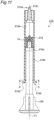
Fig. 7 is an external view of a plunger in the injector according to the first embodiment. -
Fig. 8A is an enlarged cross-sectional view of the barrel while the plunger and the movable body are stopped. -
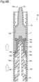
Fig. 8B is an enlarged cross-sectional view of the barrel during movement of the plunger and the movable body toward a leading end of the barrel. -
Fig. 8C is an enlarged cross-sectional view of the barrel during movement of the plunger in a direction away from the movable body. -
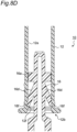
Fig. 8D is an enlarged cross-sectional view of the barrel while the plunger is restricted from coming off from the barrel by a circumferential groove. -
Fig. 9 is an enlarged cross-sectional view of a leading end portion of a barrel in an injector according to a second embodiment of the present invention. -
Fig. 10 is an enlarged cross-sectional view of a base end side portion of the barrel in the injector according to the second embodiment. -
Fig. 11 is a partial cross-sectional view of an injector according to a third embodiment of the present invention. -
Fig. 12 is a cross-sectional view of the injector taken along a line A-A shown inFig. 11 . -
Fig. 13 is an enlarged cross-sectional view of a barrel, showing stoppers when the movable body is housed in the barrel. - An injector according to the present invention comprises a cylindrical barrel including a discharge port, a seal body coming into close contact with an inner circumferential surface of the barrel, a plunger for pushing and moving the seal body to the discharge port side of the barrel, and a stopper disposed on one of the barrel and the plunger and coming into elastic contact with the other in a radial direction of the barrel. Further, the seal body and the plunger are configured to separate from each other by retracting the plunger.
- According to the present invention, the seal body can be housed into the barrel without damage and the plunger can be prevented from falling off from the barrel in the injector.
- The stopper may be a plate spring-shaped member including a fixed end attached to the plunger and a free end coming into elastic contact with the inner circumferential surface of the barrel.
- In the stopper, the free end may be located on the base end side of the barrel with respect to the fixed end.
- In the stopper, the free end may be located on the leading end side of the barrel with respect to the fixed end.
- The inner circumferential surface of the barrel may be provided with a circumferential groove with which the free end of the stopper is engaged. Since the free end of the stopper engages with the circumferential groove, the plunger is prevented from coming off from the barrel.
- The circumferential groove may have a slope surface extending from a bottom potion of the circumferential groove toward the leading end of the barrel and sloping with respect to the inner circumferential surface. As a result, the plunger can smoothly be housed into the barrel without the free end of the stopper being caught in the circumferential groove.
- The stopper may be a plate spring-shaped member including a fixed end attached to the barrel and a free end coming into elastic contact with the plunger.
- The barrel may have two slits formed to extend from a base end thereof, and wherein
the stopper may be made up of a portion of the barrel interposed between the two slits. - Embodiments of the present invention will now be described with reference to the drawings.
-
Fig. 1 is an external view of an injector according to a first embodiment of the present invention, andFig. 2 is a partial cross-sectional view of the injector. - As shown in
Figs. 1 and2 , aninjector 10 includes abarrel 12 containing, for example, a pasty fluid, amovable body 14 movably housed in thebarrel 12, and aplunger 16 for pushing and moving themovable body 14. Theinjector 10 also has anozzle tip 18 attached to aleading end 12a of thebarrel 12 and afinger grip 20 rotatably fitted to abase end 12b of thebarrel 12. -
Fig. 3 is a cross-sectional view of the barrel, andFig. 4 is an enlarged cross-sectional view of the barrel shown inFig. 3 . - As shown in
Fig. 3 , thebarrel 12 is a cylindrical member having a central axis C1, and is made of a resin material, for example. Thebarrel 12 includes adischarge port 12c at theleading end 12a and aflange portion 12d at thebase end 12b. By attaching thenozzle tip 18 to theleading end 12a of thebarrel 12, thedischarge port 12c is connected to a nozzle inside flow passage communicating with the outside in thenozzle tip 18. Theflange portion 12d functions as a stopper preventing thefinger grip 20 rotatably fitted to a base end side portion of thebarrel 12 from falling off. - As shown in
Fig. 4 , acircumferential groove 12f is formed in a base end side portion of an innercircumferential surface 12e of thebarrel 12. The reason why thecircumferential groove 12f is formed will be described later. -
Fig. 5 is a perspective view of the movable body, andFig. 6 is a partial cross-sectional view of the movable body. - As shown in
Fig. 5 , themovable body 14 is a substantially cylindrical member having a central axis C2. Themovable body 14 is made of an elastically deformable resin material, for example. Specifically, themovable body 14 is made of a material easily elastically deformed as compared to thebarrel 12. - The
movable body 14 includes amain body 14a, aseal body 14b disposed on themain body 14a, and aflange 14c disposed on themain body 14a. - The
main body 14a of themovable body 14 is cylindrical and has an outer diameter d2 smaller than an inner diameter d1 of thebarrel 12 shown inFig. 4 . Therefore, while themovable body 14 is housed in thebarrel 12, a clearance is generated between themain body 14a and the innercircumferential surface 12e of thebarrel 12. - The
seal body 14b of themovable body 14 has a disk shape and has an outer circumferential end brought into close contact with the innercircumferential surface 12e of thebarrel 12 in a slidable and fluid-tight manner. Although theseal body 14b and themain body 14a are integrated as one part, theseal body 14b and themain body 14a may be separate parts. - For close contact of the outer circumferential end with the inner
circumferential surface 12e of thebarrel 12 in a fluid-tight manner, theseal body 14b has an outer diameter d3 larger than the inner diameter d1 of thebarrel 12. The outer diameter d3 of theseal body 14b is larger than the outer diameter d2 of themain body 14a of themovable body 14. - Additionally, the
seal body 14b has a central portion attached to a front end of themain body 14a (the end closer to theleading end 12a of the barrel 12). Additionally, an outer circumferential side portion of theseal body 14b is away from themain body 14a when the portion is in a free state (when themovable body 14 is present outside the barrel 12). - The
flange 14c of themovable body 14 is a projecting portion projecting from the main body toward the inner circumferential surface of thebarrel 12 and is disposed at a rear end of themain body 14a (the end closer to thebase end 12b of the barrel 12). Theflange 14c has an outer diameter d4 smaller than the outer diameter d3 of theseal body 14b. In the case of the first embodiment, the outer diameter d4 of theflange 14c is smaller than the inner diameter d1 of thebarrel 12 and larger than the outer diameter d2 of themain body 14a. The reason why theflange 14c as described above is disposed on themovable body 14 will be described later. - For separable contact with the
plunger 16, themovable body 14 also includes a planar-shapedrear end surface 14d orthogonal to the central axis C2 and includes a non-penetrating hole-shapedguide hole 14e in therear end surface 14d. -
Fig. 7 is an external view of the plunger. - As shown in
Fig. 7 , theplunger 16 is a member for pushing and moving themovable body 14 housed in thebarrel 12 toward theleading end 12a (i.e., thedischarge port 12c) of thebarrel 12, has a central axis C3, and is made of a resin material, for example. Theplunger 16 is configured to come into separable contact with themovable body 14. - Specifically, the
plunger 16 includes acontact portion 16a coming into contact with themovable body 14 on the front end side (the side closer to theleading end 12a of the barrel 12). Thecontact portion 16a has an outer diameter d5 smaller than the inner diameter d1 of thebarrel 12. Thecontact portion 16a includes a planar-shapedcontact surface 16b coming into surface contact with the planar-shapedrear end surface 14d of themovable body 14. - The
plunger 16 includes aguide pin 16c projecting from thecontact surface 16b of thecontact portion 16a. While therear end surface 14d of themovable body 14 is in surface contact with thecontact surface 16b of theplunger 16, theguide pin 16c is received in theguide hole 14e of themovable body 14. An outer diameter d6 of theguide pin 16c is smaller than an inner diameter d7 of theguide hole 14e shown inFig. 6 so that the guide pin is received in theguide hole 14e of themovable body 14 in a manner enabling forward and backward movement. Since theguide pin 16c is guided by theguide hole 14e, thecontact surface 16b of theplunger 16 can appropriately come into surface contact with therear end surface 14d of themovable body 14. Specifically, themovable body 14 and theplunger 16 can come into contact with each other in a state in which the central axis C2 of themovable body 14 and the central axis C3 of theplunger 16 are arranged substantially on the same straight line. As a result, theplunger 16 can push and move themovable body 14 toward theleading end 12a of thebarrel 12 without tilting. - According to the
plunger 16 as described above, themovable body 14 can be pushed and moved toward theleading end 12a of thebarrel 12 by advancing theplunger 16. Additionally, themovable body 14 and theplunger 16 can be separated from each other by simply retracting theplunger 16. - Since the
plunger 16 is not fixed to themovable body 14 while theseal body 14b is in close contact with the innercircumferential surface 12e of thebarrel 12, theplunger 16 possibly comes off from thebarrel 12. For example, if theinjector 10 is in a state with thenozzle tip 18 located downward and a user grasps only theplunger 16 to lift theinjector 10, thebarrel 12 may fall off from theplunger 16 due to its own weight. - To prevent the
plunger 16 from coming off from thebarrel 12 in this way,stoppers 16d are disposed on theplunger 16 as shown inFig. 7 . - In the case of the first embodiment, the two
stoppers 16d are disposed oppositely to each other across the central axis C3 of theplunger 16. Each of the twostoppers 16d is an elastically-deformable plate spring-shaped member including afixed end 16e attached to theplunger 16 and afree end 16f displaceable in a radial direction of the barrel 12 (a direction orthogonal to the central axis C1 of the barrel 12). In the case of the first embodiment, thestoppers 16d and theplunger 16 are integrated as one part. - In the case of the first embodiment, the
free end 16f of thestopper 16d is located on thebase end 12b side of thebarrel 12 with respect to thefixed end 16e. Thefree end 16f is farther than thefixed end 16e from the central axis C3 of theplunger 16. Therefore, thestopper 16d extends from theleading end 12a side to thebase end 12b side of thebarrel 12 and toward the innercircumferential surface 12e of thebarrel 12. - As shown in
Fig. 7 , a distance L1 between the free ends 16f of the twostoppers 16d is larger than the inner diameter d1 of thebarrel 12 when the free ends are in a free state (when theplunger 16 is present outside the barrel 12). Therefore, when thestoppers 16d of theplunger 16 are located inside thebarrel 12, each of the twostoppers 16d is elastically deformed by the innercircumferential surface 12e of thebarrel 12 such that the free ends 16f come closer to each other. This brings the free ends 16f of thestopper 16d into elastic contact with the innercircumferential surface 12e of thebarrel 12 in the radial direction of thebarrel 12. As a result, a friction force is generated between thebarrel 12 and the free ends 16f of thestopper 16d, and theplunger 16 is restrained from coming off from thebarrel 12. The term "elastic contact" as used herein means that a portion of an object during elastic deformation is in contact with another object in a restoring direction in which the object is restored to an original shape. - An elastic force of the
stoppers 16d, i.e., the friction force between the innercircumferential surface 12e of thebarrel 12 and the free ends 16f of thestoppers 16d, is at a level preventing thebarrel 12 from coming off when a user grasps only theplunger 16 of theinjector 10 in a posture with thenozzle tip 18 located downward, or at a level preventing theplunger 16 from coming off when a user grasps only thebarrel 12 of theinjector 10 in a posture with thenozzle tip 18 located upward. Additionally, this elastic force (i.e., friction force) is at a level allowing the user to push and move theplunger 16 toward theleading end 12a of thebarrel 12. To achieve such an elastic force (i.e., friction force), the materials of thebarrel 12 and thestoppers 16d, the shape of thestoppers 16d, etc. are appropriately selected. - According to the
stoppers 16d as described above, theplunger 16 can be prevented from coming off from thebarrel 12 without disposing a convex portion on the innercircumferential surface 12e of thebarrel 12. Therefore, when themovable body 14 is housed into thebarrel 12, theseal body 14b is not damaged by the convex portion disposed on the innercircumferential surface 12e. - According to the
stoppers 16d as described above, theplunger 16 can be anchored at an arbitrary position on the innercircumferential surface 12e of thebarrel 12. As a result, theinjector 10 can have high usability. - Furthermore, in the case of the first embodiment, the two
stoppers 16d are arranged oppositely to each other across the central axis C3 of theplunger 16, so that the central axis C3 of theplunger 16 can be aligned with the central axis C1 of thebarrel 12. - Although the free ends 16f of the
stoppers 16d are in elastic contact with the innercircumferential surface 12e of thebarrel 12, if the user moves theplunger 16 backward, thefree end 16f slides on the innercircumferential surface 12e, and theplunger 16 finally comes off from thebarrel 12. To deal with such coming-off due to the user, as shown inFig. 4 , thecircumferential groove 12f is formed in a portion near thebase end 12b in the innercircumferential surface 12e of thebarrel 12. The free ends 16f of thestoppers 16d engage with (fall and fit into) thecircumferential groove 12f, so that theplunger 16 is restricted from moving toward the base end side of thebarrel 12, and as a result, theplunger 16 is prevented from coming off from thebarrel 12. - When the
plunger 16 is housed into thebarrel 12, the free ends 16f of thestoppers 16d may be caught in thecircumferential groove 12f, which possibly makes it unable to smoothly move theplunger 16 toward theleading end 12a of thebarrel 12. As a countermeasure, as shown inFig. 4 , thecircumferential groove 12f includes aslope surface 12g extending from a bottom potion thereof toward theleading end 12a of thebarrel 12 and sloping with respect to the innercircumferential surface 12e. Due to theslope surface 12g, thefree end 16f falling into thecircumferential groove 12f can return onto the innercircumferential surface 12e. As a result, the free ends 16f of thestoppers 16d can pass through thecircumferential groove 12f without being caught. - When the
movable body 14 is housed into thebarrel 12, theslope surface 12g can also prevent theseal body 14b of themovable body 14 from being caught in thecircumferential groove 12f. As a result, theseal body 14b can be prevented from being damaged by thecircumferential groove 12f. - While describing the operation of the
injector 10 according to the first embodiment, other features of theinjector 10 will hereinafter be described with reference toFigs. 8A to 8D . -
Fig. 8A is an enlarged cross-sectional view of the barrel while the plunger and the movable body are stopped. - As shown in
Fig. 8A , theseal body 14b of themovable body 14 is in close fluid-tight contact with the innercircumferential surface 12e of thebarrel 12, so that a fluid F is contained in thebarrel 12 without leaking from the base end side of thebarrel 12 to the outside. -
Fig. 8B is an enlarged cross-sectional view of the barrel during movement of the plunger and the movable body toward the leading end of the barrel. - As shown in
Fig. 8B , while therear end surface 14d of themovable body 14 and thecontact surface 16b of theplunger 16 are in contact with each other, themovable body 14 is pushed and moved toward theleading end 12a of thebarrel 12 by theplunger 16. During movement of themovable body 14, theseal body 14b is elastically deformed. Specifically, due to the friction force generated between the outer circumferential end of theseal body 14b and the innercircumferential surface 12e of thebarrel 12, theseal body 14b is elastically deformed such that the outer circumferential side portion of theseal body 14b approaches themain body 14a. Theseal body 14b moves in this elastically deformed state and pushes and moves the fluid F toward thedischarge port 12c. -
Fig. 8C is an enlarged cross-sectional view of the barrel during movement of the plunger in a direction away from the movable body. - As shown in
Fig. 8C , when theplunger 16 moves in a direction away from themovable body 14, i.e., toward the base end of thebarrel 12, themovable body 14 is separated from theplunger 16 and stops in thebarrel 12 in this state. - Immediately after the
movable body 14 stops, as shown inFig. 8A , theseal body 14b is returned (restored) to the original shape with the outer circumferential side portion separated from themain body 14a. In this case, themovable body 14 entirely retracts toward the base end of thebarrel 12 without changing the contact position on the innercircumferential surface 12e of thebarrel 12 in contact with the outer circumferential end of theseal body 14b. As a result, the fluid F in thenozzle tip 18 is drawn toward theseal body 14b, and the subsequent dripping of the fluid F is suppressed. - To allow the
movable body 14 to retract toward the base end of thebarrel 12 through the restoration of theseal body 14b without changing the position of contact of theseal body 14b with thebarrel 12, theplunger 16 needs to retreat at the same time. In other words, a restoring force of theseal body 14b needs to exceed the friction force between the free ends 16f of thestoppers 16d of theplunger 16 and the innercircumferential surface 12e of thebarrel 12. For this purpose, the material of theseal body 14b, the shape of theseal body 14b, etc. are appropriately selected. - When the
movable body 14 retracts through the restoration of theseal body 14b without changing the position of contact of theseal body 14b with thebarrel 12 as described above, theflange 14c is moved along the innercircumferential surface 12e of thebarrel 12. As a result, themovable body 14 can retreat in the extending direction of the central axis C1 of thebarrel 12. If theflange 14c does not exit, themovable body 14 retracts in a direction tilted with respect to the central axis C1 of thebarrel 12, so that themovable body 14 may have a posture in which a portion of an outer edge of therear end surface 14d comes into contact with the innercircumferential surface 12e of thebarrel 12, i.e., a tilted posture. If themovable body 14 is tilted, the adhesion between theseal body 14b and the innercircumferential surface 12e of thebarrel 12 is partially weakened, so that the fluid F may leak to the base end side of thebarrel 12. - In the case of the first embodiment, the outer diameter d4 of the
flange 14c of themovable body 14 is smaller than the inner diameter d1 of thebarrel 12. Therefore, theflange 14c can be moved without strong contact with the innercircumferential surface 12e of thebarrel 12, i.e., in a state of substantially zero friction force. Alternatively, the outer diameter d4 of theflange 14c of themovable body 14 may be equal to or larger than the inner diameter d1 of thebarrel 12. However, the friction force between theflange 14c and thebarrel 12 must be smaller than the friction force between theseal body 14b and thebarrel 12. Otherwise, the restoration of theseal body 14b and the retraction of themovable body 14 due to the restoration cannot be achieved. - In the case of the first embodiment, as shown in
Fig. 6 , the distance L2 between theseal body 14b and theflange 14c in themovable body 14 is made larger than the outer diameter d3 of theseal body 14b. Therefore, when themovable body 14 retracts due to the restoration of theseal body 14b, themovable body 14 is hardly tilted (as compared to when the distance L2 is smaller than the outer diameter d3). - As shown in
Fig. 8C , theplunger 16 separated from themovable body 14 is kept housed in thebarrel 12 by thestoppers 16d without coming off from thebarrel 12. -
Fig. 8D is a partially enlarged cross-sectional view of the barrel while the plunger is restricted from coming off from the barrel by the circumferential groove. - As shown in
Fig. 8D , theplunger 16 during retraction toward the base end of thebarrel 12 due to pulling by the user is restrained by engagement of the free ends 16f of thestoppers 16d with thecircumferential groove 12f. As a result, theplunger 16 is prevented from coming off from thebarrel 12. - According to the first embodiment as described above, the seal body can be housed into the barrel without damage and the plunger can be prevented from falling off from the barrel in the injector.
- A second embodiment is substantially the same as the first embodiment as descried above except that the form of the stoppers disposed on the plunger is different. Therefore, the second embodiment will be described mainly in terms of different points. The same reference numerals are given to constituent elements in the second embodiment that are substantially the same as the constituent elements in the first embodiment described above.
-
Fig. 9 is an enlarged cross-sectional view of a leading end side portion of a barrel in an injector according to the second embodiment.Fig. 10 is an enlarged cross-sectional view of a base end side portion of the barrel. - As shown in
Fig. 9 , in aninjector 110 according to the second embodiment, aplunger 116 includesstoppers 116d. Each of thestoppers 116d is a plate spring-shaped member including afixed end 116e attached to theplunger 116 and afree end 116f elastically contacting the innercircumferential surface 12e of thebarrel 12. - In the case of the second embodiment, unlike the
stopper 16d of the first embodiment, thefree end 116f of thestopper 116d is located on the leading end side of thebarrel 12 with respect to thefixed end 116e. Therefore, acontact surface 116b of theplunger 116 coming into contact with therear end surface 14d of themovable body 14 is closer to thefree end 116f of thestopper 116d as compared to the first embodiment shown inFig. 8D . - Thus, as shown in
Fig. 10 , when thefree end 116f of thestopper 116d is engaged with the circumferential groove of thebarrel 12, thecontact surface 116b of theplunger 116 is located closer to thebase end 12b of thebarrel 12. In other words, themovable body 14 having therear end surface 14d brought into contact with thecontact surface 116b is also disposed closer to thebase end 12b of thebarrel 12. As a result, a larger amount of the fluid can be contained in thebarrel 12. - In the second embodiment as described above, as with the first embodiment, the seal body can be housed into the barrel without damage and the plunger can be prevented from falling off from the barrel in the injector.
- In the case of the first embodiment described above, the stoppers preventing the plunger from coming off from the barrel are disposed on the plunger. In contrast, in the case of a third embodiment, stoppers are disposed on the barrel. Therefore, the third embodiment will be described mainly in terms of the different stoppers. The same reference numerals are given to constituent elements in the third embodiment that are substantially the same as the constituent elements in the first embodiment described above.
-
Fig. 11 is a partial cross-sectional view of an injector according to the third embodiment.Fig. 12 is a cross-sectional view of the injector taken along a line A-A shown inFig. 11 .Fig. 13 is an enlarged cross-sectional view of a barrel, showing stoppers when the movable body is housed into the barrel. InFig. 11 , the nozzle tip and the finger grip are not shown. - As shown in
Figs. 11 and12 , in aninjector 210 according to the third embodiment, no stopper is disposed on aplunger 216. Instead, as shown inFig. 12 , a pair ofstoppers 212f facing each other is disposed on abarrel 212. - Specifically, in the case of the third embodiment, the
stoppers 212f are made up of portions of thebarrel 212 each interposed between twoslits 212g formed to extend from abase end 212b of thebarrel 212. As a result, a portion of thebarrel 212 interposed between base portions of the twoslits 212g is defined as afixed end 212h of thestopper 212f. Aclaw 212j brought into elastic contact with theplunger 216 is disposed on the inner side of afree end 212i of each of the pairedstoppers 212f. Therefore, thestopper 212f is a plate spring-shaped member (a plate spring-shaped member integrated with the barrel 212) having thefixed end 212h attached to thebarrel 212 and thefree end 212i brought into elastic contact with the plunger 216 (via theclaws 212j). - A distance between the
claws 212j of the pair of thestoppers 212f is made smaller than an outer diameter of ashaft portion 216b of theplunger 216. As a result, the pair of theclaws 212j holds theshaft portion 216b of theplunger 216. Consequently, theplunger 216 is prevented from coming off from thebarrel 212. - The
plunger 216 during retraction toward thebase end 212b of thebarrel 212 due to pulling by the user is restrained when acontact portion 216a for contact with themovable body 14 is brought into contact with theclaws 212j. As a result, theplunger 216 is prevented from coming off from thebarrel 212. - As shown in
Fig. 13 , when themovable body 14 is housed into thebarrel 212, the pair of thestoppers 212f is elastically deformed such that the free ends 212i move away from each other. As a result, themovable body 14 can be housed into thebarrel 212 without bringing theclaws 212j of thestoppers 212f into contact with theseal body 14b. - In the third embodiment as described above, as with the first embodiment, the seal body can be housed into the barrel without damage and the plunger can be prevented from falling off from the barrel in the injector.
- Although the present invention has been described with three embodiments, the present invention is defined by the appended claims and not limited to these embodiments.
- The present invention is applicable to any injector for injecting a fluid.
-
- 10
- injector
- 12
- barrel
- 12e
- inner circumferential surface
- 14b
- seal body
- 16
- plunger
- 16d
- stopper
Claims (9)
- An injector (10, 110, 210) comprising:a cylindrical barrel (12, 212) including a discharge port (12c);a movable body (14) including a main body (14a), a seal body (14b) disposed on the main body (14a) and a flange (14c) disposed on the main body (14a), the seal body (14b) coming into close contact with an inner circumferential surface (12e) of the barrel (12, 212), the movable body (14) being restored to an original shape when the movable body stops moving, the original shape being a shape where an outer circumferential side portion of the seal body (14b) is separated from the main body (14a);a plunger (16, 116, 216) for pushing and moving the seal body (14b) to the discharge port (12c) side of the barrel (12); anda stopper (16d, 116d, 212f) disposed on one of the barrel (12, 212) and the plunger (16, 116, 216) and coming into elastic contact with the other in a radial direction of the barrel (12, 212),wherein the seal body (14b) and the plunger (16, 116, 216) are configured to separate from each other when the plunger (16, 116, 216) is being retracted.
- The injector (10, 110) according to claim 1, wherein the stopper (16d, 116d) is a plate spring-shaped member including a fixed end (16e, 116e) attached to the plunger (16, 116) and a free end (16f, 116f) coming into elastic contact with the inner circumferential surface (12e) of the barrel (12).
- The injector (10) according to claim 2, wherein in the stopper (16d), the free end (16f) is located on the base end (12b) side of the barrel (12) with respect to the fixed end (16e).
- The injector (110) according to claim 2, wherein in the stopper (116d), the free end (116f) is located on the leading end (12a) side of the barrel (12) with respect to the fixed end (116e).
- The injector (10, 110) according to any one of claims 2 to 4, wherein the inner circumferential surface (12e) of the barrel (12) is provided with a circumferential groove (12f) with which the free end (16f, 116f) of the stopper (16d, 116d) is engaged.
- The injector (10, 110) according to claim 5, wherein the circumferential groove (12f) has a slope surface (12g) extending from a bottom potion of the circumferential groove (12f) toward the leading end (12a) of the barrel (12) and sloping with respect to the inner circumferential surface (12e).
- The injector (10, 110) according to any one of claims 2 to 6, wherein the stopper (16d, 116d) and the plunger (16, 116) are integrated as one part.
- The injector (210) according to claim 1, wherein the stopper (212f) is a plate spring-shaped member including a fixed end (212h) attached to the barrel (212) and a free end (212i) coming into elastic contact with the plunger (216).
- The injector (210) according to claim 8, whereinthe barrel (212) has two slits (212g) formed to extend from a base end (212b) thereof, and whereinthe stopper (212f) is made up of a portion of the barrel (212) interposed between the two slits (212g).
Applications Claiming Priority (1)
| Application Number | Priority Date | Filing Date | Title |
|---|---|---|---|
| JP2018118258A JP7107499B2 (en) | 2018-06-21 | 2018-06-21 | injector |
Publications (2)
| Publication Number | Publication Date |
|---|---|
| EP3586894A1 EP3586894A1 (en) | 2020-01-01 |
| EP3586894B1 true EP3586894B1 (en) | 2025-04-30 |
Family
ID=66998274
Family Applications (1)
| Application Number | Title | Priority Date | Filing Date |
|---|---|---|---|
| EP19181122.3A Active EP3586894B1 (en) | 2018-06-21 | 2019-06-19 | Injector |
Country Status (4)
| Country | Link |
|---|---|
| US (1) | US11319139B2 (en) |
| EP (1) | EP3586894B1 (en) |
| JP (1) | JP7107499B2 (en) |
| CN (1) | CN110624158B (en) |
Families Citing this family (1)
| Publication number | Priority date | Publication date | Assignee | Title |
|---|---|---|---|---|
| US20210128840A1 (en) * | 2018-04-09 | 2021-05-06 | Sio2 Medical Products, Inc. | Stretchable plunger assemblies |
Citations (1)
| Publication number | Priority date | Publication date | Assignee | Title |
|---|---|---|---|---|
| US20080275387A1 (en) * | 2007-05-03 | 2008-11-06 | Yeadon Stephen C | Hemostatic medical device |
Family Cites Families (30)
| Publication number | Priority date | Publication date | Assignee | Title |
|---|---|---|---|---|
| JPS5737429B2 (en) | 1973-12-12 | 1982-08-10 | ||
| JPS5393660A (en) | 1977-01-28 | 1978-08-16 | Hitachi Ltd | Electric cleaner |
| CH620126A5 (en) * | 1978-03-10 | 1980-11-14 | Tulcea Sa | |
| JPS6091514A (en) | 1983-10-25 | 1985-05-22 | 株式会社東芝 | Device for operating switch |
| US4826484A (en) * | 1987-03-13 | 1989-05-02 | Habley Medical Technology Corporation | Disease control syringe having a retractable needle |
| IN169618B (en) * | 1987-06-25 | 1991-11-23 | Agven Medical Corp Ltd | |
| US4781684A (en) * | 1987-09-03 | 1988-11-01 | Trenner Lewis E | Single use disposable hypodermic syringe |
| US4758232A (en) * | 1987-09-08 | 1988-07-19 | Chak Choi K | Suction syringe with an automatic locking means |
| WO1989004187A2 (en) * | 1987-11-06 | 1989-05-18 | Louis Paul Ellgass | Non-reusable syringe |
| US5106372A (en) * | 1991-05-03 | 1992-04-21 | Sherwood Medical Company | Single use syringe |
| US5380295A (en) | 1992-12-14 | 1995-01-10 | Mallinckrodt Medical, Inc. | Delivery apparatus with mechanism preventing rearward movement of a piston disposed therein |
| US5370620A (en) * | 1992-12-28 | 1994-12-06 | Shonfeld; David | Single use hypodermic syringe |
| JPH09253205A (en) | 1996-03-22 | 1997-09-30 | Shirouma Sci Kk | Contents filling injector type container made of resin by injection molding |
| JP2002515268A (en) | 1998-04-30 | 2002-05-28 | アボット・ラボラトリーズ | Syringe assembly |
| JP4133071B2 (en) * | 2001-08-20 | 2008-08-13 | 大成化工株式会社 | Anti-sagging injector, and plunger and seal body for the injector |
| JP4141156B2 (en) * | 2002-03-15 | 2008-08-27 | 日本ベクトン・ディッキンソン株式会社 | Prefilled syringe with plunger retraction limit mechanism |
| GB0213555D0 (en) * | 2002-06-13 | 2002-07-24 | Star Syringe Ltd | Needlestick prevention device |
| US6872191B2 (en) * | 2002-07-08 | 2005-03-29 | M.K. Meditech Co., Ltd. | Self-destructive syringe |
| JP4738420B2 (en) * | 2004-12-21 | 2011-08-03 | ベクトン・ディキンソン・アンド・カンパニー | Syringe assembly with disabling mechanism |
| US8740856B2 (en) * | 2007-06-04 | 2014-06-03 | Becton, Dickinson And Company | Stoppers used in pre-filled syringes |
| NZ582278A (en) | 2007-06-12 | 2012-07-27 | Becton Dickinson Co | Syringe with disabling lock to prevent reuse and an indicator for showing the position of the lock |
| MX2011013671A (en) * | 2009-06-26 | 2012-01-20 | Becton Dickinson Co | Passive reuse prevention syringe that uses a flange lock. |
| CN101628139B (en) | 2009-08-19 | 2012-03-14 | 江振标 | Lock structure of safety self-destruction injector |
| JP5090555B2 (en) | 2011-04-04 | 2012-12-05 | 第一レジン工業株式会社 | Syringe |
| US20130123712A1 (en) | 2011-11-11 | 2013-05-16 | Becton, Dickinson And Company | Plunger Rod Retaining Anchors |
| FR2987746B1 (en) | 2012-03-08 | 2015-04-10 | Adip Sculpt | SYRINGE FOR MEDICAL APPLICATION |
| WO2015117131A1 (en) * | 2014-02-03 | 2015-08-06 | Unitract Syringe Pty Ltd | Expanding plunger rods for syringes |
| WO2017011599A1 (en) * | 2015-07-14 | 2017-01-19 | Sio2 Medical Products, Inc. | Convertible plungers and methods for assembling the same in a medical barrel |
| JP6579918B2 (en) * | 2015-10-29 | 2019-09-25 | 株式会社吉野工業所 | Syringe type ejector |
| US10286151B2 (en) * | 2016-02-26 | 2019-05-14 | West Pharma. Services IL, Ltd. | Plunger with reduced leakage during storage |
-
2018
- 2018-06-21 JP JP2018118258A patent/JP7107499B2/en active Active
-
2019
- 2019-06-19 EP EP19181122.3A patent/EP3586894B1/en active Active
- 2019-06-19 US US16/445,299 patent/US11319139B2/en active Active
- 2019-06-20 CN CN201910536183.1A patent/CN110624158B/en active Active
Patent Citations (1)
| Publication number | Priority date | Publication date | Assignee | Title |
|---|---|---|---|---|
| US20080275387A1 (en) * | 2007-05-03 | 2008-11-06 | Yeadon Stephen C | Hemostatic medical device |
Also Published As
| Publication number | Publication date |
|---|---|
| CN110624158A (en) | 2019-12-31 |
| JP7107499B2 (en) | 2022-07-27 |
| EP3586894A1 (en) | 2020-01-01 |
| CN110624158B (en) | 2023-10-27 |
| US11319139B2 (en) | 2022-05-03 |
| JP2019217106A (en) | 2019-12-26 |
| US20190389646A1 (en) | 2019-12-26 |
Similar Documents
| Publication | Publication Date | Title |
|---|---|---|
| EP2175917B1 (en) | Injection device with locking mechanism for syringe carrier | |
| EP3856292B1 (en) | Safety syringe | |
| US5263934A (en) | Stroke limiting syringe with retractable needle | |
| US6592555B1 (en) | Syringe device | |
| US6676641B2 (en) | Retractable hypodermic syringe | |
| EP2175914B1 (en) | Injection device with locking mechanism for syringe carrier | |
| US20090054838A1 (en) | Injection device | |
| US20060106340A1 (en) | Injection syringe with retractable needle | |
| MX2013000841A (en) | Dual chamber syringe with retractable needle. | |
| SE467521B (en) | PRE-FILLED SPRAY | |
| KR20040023689A (en) | Luer connector assembly | |
| EA017822B1 (en) | Injection device | |
| USRE49516E1 (en) | Syringe and method for assembling it | |
| AU2004226915B1 (en) | Disposable syringe with a retractable needle | |
| HU213691B (en) | Syringe | |
| EP3586895B1 (en) | Injector | |
| US20060111674A1 (en) | Device for injecting a product, in particular for medical use | |
| KR102228078B1 (en) | Safety syringe | |
| EP3586894A1 (en) | Injector | |
| US20050228344A1 (en) | Spring loaded automatic retractable needle syringe | |
| EP4201453A1 (en) | Safety device for shielding an injection needle of a medical container, and an injection device including this safety device | |
| PL203446B1 (en) | Disposable syringe with retractable needle |
Legal Events
| Date | Code | Title | Description |
|---|---|---|---|
| PUAI | Public reference made under article 153(3) epc to a published international application that has entered the european phase |
Free format text: ORIGINAL CODE: 0009012 |
|
| STAA | Information on the status of an ep patent application or granted ep patent |
Free format text: STATUS: THE APPLICATION HAS BEEN PUBLISHED |
|
| AK | Designated contracting states |
Kind code of ref document: A1 Designated state(s): AL AT BE BG CH CY CZ DE DK EE ES FI FR GB GR HR HU IE IS IT LI LT LU LV MC MK MT NL NO PL PT RO RS SE SI SK SM TR |
|
| AX | Request for extension of the european patent |
Extension state: BA ME |
|
| STAA | Information on the status of an ep patent application or granted ep patent |
Free format text: STATUS: REQUEST FOR EXAMINATION WAS MADE |
|
| 17P | Request for examination filed |
Effective date: 20200701 |
|
| RBV | Designated contracting states (corrected) |
Designated state(s): AL AT BE BG CH CY CZ DE DK EE ES FI FR GB GR HR HU IE IS IT LI LT LU LV MC MK MT NL NO PL PT RO RS SE SI SK SM TR |
|
| STAA | Information on the status of an ep patent application or granted ep patent |
Free format text: STATUS: EXAMINATION IS IN PROGRESS |
|
| 17Q | First examination report despatched |
Effective date: 20220202 |
|
| GRAP | Despatch of communication of intention to grant a patent |
Free format text: ORIGINAL CODE: EPIDOSNIGR1 |
|
| STAA | Information on the status of an ep patent application or granted ep patent |
Free format text: STATUS: GRANT OF PATENT IS INTENDED |
|
| INTG | Intention to grant announced |
Effective date: 20241122 |
|
| GRAS | Grant fee paid |
Free format text: ORIGINAL CODE: EPIDOSNIGR3 |
|
| GRAA | (expected) grant |
Free format text: ORIGINAL CODE: 0009210 |
|
| STAA | Information on the status of an ep patent application or granted ep patent |
Free format text: STATUS: THE PATENT HAS BEEN GRANTED |
|
| AK | Designated contracting states |
Kind code of ref document: B1 Designated state(s): AL AT BE BG CH CY CZ DE DK EE ES FI FR GB GR HR HU IE IS IT LI LT LU LV MC MK MT NL NO PL PT RO RS SE SI SK SM TR |
|
| P01 | Opt-out of the competence of the unified patent court (upc) registered |
Free format text: CASE NUMBER: APP_14446/2025 Effective date: 20250325 |
|
| REG | Reference to a national code |
Ref country code: CH Ref legal event code: EP Ref country code: GB Ref legal event code: FG4D |
|
| REG | Reference to a national code |
Ref country code: DE Ref legal event code: R096 Ref document number: 602019069247 Country of ref document: DE |
|
| REG | Reference to a national code |
Ref country code: IE Ref legal event code: FG4D |
|
| REG | Reference to a national code |
Ref country code: NL Ref legal event code: MP Effective date: 20250430 |
|
| REG | Reference to a national code |
Ref country code: AT Ref legal event code: MK05 Ref document number: 1789471 Country of ref document: AT Kind code of ref document: T Effective date: 20250430 |
|
| PG25 | Lapsed in a contracting state [announced via postgrant information from national office to epo] |
Ref country code: FI Free format text: LAPSE BECAUSE OF FAILURE TO SUBMIT A TRANSLATION OF THE DESCRIPTION OR TO PAY THE FEE WITHIN THE PRESCRIBED TIME-LIMIT Effective date: 20250430 Ref country code: ES Free format text: LAPSE BECAUSE OF FAILURE TO SUBMIT A TRANSLATION OF THE DESCRIPTION OR TO PAY THE FEE WITHIN THE PRESCRIBED TIME-LIMIT Effective date: 20250430 Ref country code: PT Free format text: LAPSE BECAUSE OF FAILURE TO SUBMIT A TRANSLATION OF THE DESCRIPTION OR TO PAY THE FEE WITHIN THE PRESCRIBED TIME-LIMIT Effective date: 20250901 |
|
| PGFP | Annual fee paid to national office [announced via postgrant information from national office to epo] |
Ref country code: DE Payment date: 20250701 Year of fee payment: 7 |
|
| REG | Reference to a national code |
Ref country code: LT Ref legal event code: MG9D |
|
| PG25 | Lapsed in a contracting state [announced via postgrant information from national office to epo] |
Ref country code: NO Free format text: LAPSE BECAUSE OF FAILURE TO SUBMIT A TRANSLATION OF THE DESCRIPTION OR TO PAY THE FEE WITHIN THE PRESCRIBED TIME-LIMIT Effective date: 20250730 Ref country code: GR Free format text: LAPSE BECAUSE OF FAILURE TO SUBMIT A TRANSLATION OF THE DESCRIPTION OR TO PAY THE FEE WITHIN THE PRESCRIBED TIME-LIMIT Effective date: 20250731 |
|
| PG25 | Lapsed in a contracting state [announced via postgrant information from national office to epo] |
Ref country code: PL Free format text: LAPSE BECAUSE OF FAILURE TO SUBMIT A TRANSLATION OF THE DESCRIPTION OR TO PAY THE FEE WITHIN THE PRESCRIBED TIME-LIMIT Effective date: 20250430 Ref country code: NL Free format text: LAPSE BECAUSE OF FAILURE TO SUBMIT A TRANSLATION OF THE DESCRIPTION OR TO PAY THE FEE WITHIN THE PRESCRIBED TIME-LIMIT Effective date: 20250430 |
|
| PG25 | Lapsed in a contracting state [announced via postgrant information from national office to epo] |
Ref country code: BG Free format text: LAPSE BECAUSE OF FAILURE TO SUBMIT A TRANSLATION OF THE DESCRIPTION OR TO PAY THE FEE WITHIN THE PRESCRIBED TIME-LIMIT Effective date: 20250430 |
|
| PG25 | Lapsed in a contracting state [announced via postgrant information from national office to epo] |
Ref country code: HR Free format text: LAPSE BECAUSE OF FAILURE TO SUBMIT A TRANSLATION OF THE DESCRIPTION OR TO PAY THE FEE WITHIN THE PRESCRIBED TIME-LIMIT Effective date: 20250430 |
|
| PG25 | Lapsed in a contracting state [announced via postgrant information from national office to epo] |
Ref country code: AT Free format text: LAPSE BECAUSE OF FAILURE TO SUBMIT A TRANSLATION OF THE DESCRIPTION OR TO PAY THE FEE WITHIN THE PRESCRIBED TIME-LIMIT Effective date: 20250430 |
|
| PG25 | Lapsed in a contracting state [announced via postgrant information from national office to epo] |
Ref country code: RS Free format text: LAPSE BECAUSE OF FAILURE TO SUBMIT A TRANSLATION OF THE DESCRIPTION OR TO PAY THE FEE WITHIN THE PRESCRIBED TIME-LIMIT Effective date: 20250731 |
|
| PG25 | Lapsed in a contracting state [announced via postgrant information from national office to epo] |
Ref country code: IS Free format text: LAPSE BECAUSE OF FAILURE TO SUBMIT A TRANSLATION OF THE DESCRIPTION OR TO PAY THE FEE WITHIN THE PRESCRIBED TIME-LIMIT Effective date: 20250830 |
|
| PG25 | Lapsed in a contracting state [announced via postgrant information from national office to epo] |
Ref country code: LV Free format text: LAPSE BECAUSE OF FAILURE TO SUBMIT A TRANSLATION OF THE DESCRIPTION OR TO PAY THE FEE WITHIN THE PRESCRIBED TIME-LIMIT Effective date: 20250430 |
|
| PG25 | Lapsed in a contracting state [announced via postgrant information from national office to epo] |
Ref country code: DK Free format text: LAPSE BECAUSE OF FAILURE TO SUBMIT A TRANSLATION OF THE DESCRIPTION OR TO PAY THE FEE WITHIN THE PRESCRIBED TIME-LIMIT Effective date: 20250430 Ref country code: SM Free format text: LAPSE BECAUSE OF FAILURE TO SUBMIT A TRANSLATION OF THE DESCRIPTION OR TO PAY THE FEE WITHIN THE PRESCRIBED TIME-LIMIT Effective date: 20250430 |
|
| PG25 | Lapsed in a contracting state [announced via postgrant information from national office to epo] |
Ref country code: CZ Free format text: LAPSE BECAUSE OF FAILURE TO SUBMIT A TRANSLATION OF THE DESCRIPTION OR TO PAY THE FEE WITHIN THE PRESCRIBED TIME-LIMIT Effective date: 20250430 |
|
| PG25 | Lapsed in a contracting state [announced via postgrant information from national office to epo] |
Ref country code: EE Free format text: LAPSE BECAUSE OF FAILURE TO SUBMIT A TRANSLATION OF THE DESCRIPTION OR TO PAY THE FEE WITHIN THE PRESCRIBED TIME-LIMIT Effective date: 20250430 |
|
| PG25 | Lapsed in a contracting state [announced via postgrant information from national office to epo] |
Ref country code: SK Free format text: LAPSE BECAUSE OF FAILURE TO SUBMIT A TRANSLATION OF THE DESCRIPTION OR TO PAY THE FEE WITHIN THE PRESCRIBED TIME-LIMIT Effective date: 20250430 Ref country code: RO Free format text: LAPSE BECAUSE OF FAILURE TO SUBMIT A TRANSLATION OF THE DESCRIPTION OR TO PAY THE FEE WITHIN THE PRESCRIBED TIME-LIMIT Effective date: 20250430 |
|
| REG | Reference to a national code |
Ref country code: CH Ref legal event code: H13 Free format text: ST27 STATUS EVENT CODE: U-0-0-H10-H13 (AS PROVIDED BY THE NATIONAL OFFICE) Effective date: 20260127 |
|
| PG25 | Lapsed in a contracting state [announced via postgrant information from national office to epo] |
Ref country code: IT Free format text: LAPSE BECAUSE OF FAILURE TO SUBMIT A TRANSLATION OF THE DESCRIPTION OR TO PAY THE FEE WITHIN THE PRESCRIBED TIME-LIMIT Effective date: 20250430 |
|
| PG25 | Lapsed in a contracting state [announced via postgrant information from national office to epo] |
Ref country code: MC Free format text: LAPSE BECAUSE OF FAILURE TO SUBMIT A TRANSLATION OF THE DESCRIPTION OR TO PAY THE FEE WITHIN THE PRESCRIBED TIME-LIMIT Effective date: 20250430 |
|
| REG | Reference to a national code |
Ref country code: DE Ref legal event code: R097 Ref document number: 602019069247 Country of ref document: DE |
|
| PG25 | Lapsed in a contracting state [announced via postgrant information from national office to epo] |
Ref country code: LU Free format text: LAPSE BECAUSE OF NON-PAYMENT OF DUE FEES Effective date: 20250619 |
|
| REG | Reference to a national code |
Ref country code: BE Ref legal event code: MM Effective date: 20250630 |
|
| PLBE | No opposition filed within time limit |
Free format text: ORIGINAL CODE: 0009261 |
|
| STAA | Information on the status of an ep patent application or granted ep patent |
Free format text: STATUS: NO OPPOSITION FILED WITHIN TIME LIMIT |
|
| REG | Reference to a national code |
Ref country code: CH Ref legal event code: L10 Free format text: ST27 STATUS EVENT CODE: U-0-0-L10-L00 (AS PROVIDED BY THE NATIONAL OFFICE) Effective date: 20260311 |
|
| GBPC | Gb: european patent ceased through non-payment of renewal fee |
Effective date: 20250730 |
|
| 26N | No opposition filed |
Effective date: 20260202 |
|
| PG25 | Lapsed in a contracting state [announced via postgrant information from national office to epo] |
Ref country code: GB Free format text: LAPSE BECAUSE OF NON-PAYMENT OF DUE FEES Effective date: 20250730 |
|
| PG25 | Lapsed in a contracting state [announced via postgrant information from national office to epo] |
Ref country code: IE Free format text: LAPSE BECAUSE OF NON-PAYMENT OF DUE FEES Effective date: 20250619 |
|
| PG25 | Lapsed in a contracting state [announced via postgrant information from national office to epo] |
Ref country code: BE Free format text: LAPSE BECAUSE OF NON-PAYMENT OF DUE FEES Effective date: 20250630 |
|
| PG25 | Lapsed in a contracting state [announced via postgrant information from national office to epo] |
Ref country code: FR Free format text: LAPSE BECAUSE OF NON-PAYMENT OF DUE FEES Effective date: 20250630 |
|
| PG25 | Lapsed in a contracting state [announced via postgrant information from national office to epo] |
Ref country code: CH Free format text: LAPSE BECAUSE OF NON-PAYMENT OF DUE FEES Effective date: 20250630 |