EP3586778A1 - Reinforcement for irrigated electrophysiology balloon catheter with flexible-circuit electrodes - Google Patents
Reinforcement for irrigated electrophysiology balloon catheter with flexible-circuit electrodes Download PDFInfo
- Publication number
- EP3586778A1 EP3586778A1 EP19183327.6A EP19183327A EP3586778A1 EP 3586778 A1 EP3586778 A1 EP 3586778A1 EP 19183327 A EP19183327 A EP 19183327A EP 3586778 A1 EP3586778 A1 EP 3586778A1
- Authority
- EP
- European Patent Office
- Prior art keywords
- catheter
- balloon
- reinforcement
- tails
- disposed
- Prior art date
- Legal status (The legal status is an assumption and is not a legal conclusion. Google has not performed a legal analysis and makes no representation as to the accuracy of the status listed.)
- Granted
Links
Images




Classifications
-
- A—HUMAN NECESSITIES
- A61—MEDICAL OR VETERINARY SCIENCE; HYGIENE
- A61M—DEVICES FOR INTRODUCING MEDIA INTO, OR ONTO, THE BODY; DEVICES FOR TRANSDUCING BODY MEDIA OR FOR TAKING MEDIA FROM THE BODY; DEVICES FOR PRODUCING OR ENDING SLEEP OR STUPOR
- A61M25/00—Catheters; Hollow probes
- A61M25/10—Balloon catheters
- A61M25/1002—Balloon catheters characterised by balloon shape
-
- A—HUMAN NECESSITIES
- A61—MEDICAL OR VETERINARY SCIENCE; HYGIENE
- A61B—DIAGNOSIS; SURGERY; IDENTIFICATION
- A61B18/00—Surgical instruments, devices or methods for transferring non-mechanical forms of energy to or from the body
- A61B18/04—Surgical instruments, devices or methods for transferring non-mechanical forms of energy to or from the body by heating
- A61B18/12—Surgical instruments, devices or methods for transferring non-mechanical forms of energy to or from the body by heating by passing a current through the tissue to be heated, e.g. high-frequency current
-
- A—HUMAN NECESSITIES
- A61—MEDICAL OR VETERINARY SCIENCE; HYGIENE
- A61B—DIAGNOSIS; SURGERY; IDENTIFICATION
- A61B18/00—Surgical instruments, devices or methods for transferring non-mechanical forms of energy to or from the body
- A61B18/04—Surgical instruments, devices or methods for transferring non-mechanical forms of energy to or from the body by heating
- A61B18/12—Surgical instruments, devices or methods for transferring non-mechanical forms of energy to or from the body by heating by passing a current through the tissue to be heated, e.g. high-frequency current
- A61B18/14—Probes or electrodes therefor
- A61B18/1492—Probes or electrodes therefor having a flexible, catheter-like structure, e.g. for heart ablation
-
- A—HUMAN NECESSITIES
- A61—MEDICAL OR VETERINARY SCIENCE; HYGIENE
- A61B—DIAGNOSIS; SURGERY; IDENTIFICATION
- A61B5/00—Measuring for diagnostic purposes; Identification of persons
- A61B5/24—Detecting, measuring or recording bioelectric or biomagnetic signals of the body or parts thereof
- A61B5/25—Bioelectric electrodes therefor
- A61B5/279—Bioelectric electrodes therefor specially adapted for particular uses
- A61B5/28—Bioelectric electrodes therefor specially adapted for particular uses for electrocardiography [ECG]
- A61B5/283—Invasive
-
- A—HUMAN NECESSITIES
- A61—MEDICAL OR VETERINARY SCIENCE; HYGIENE
- A61B—DIAGNOSIS; SURGERY; IDENTIFICATION
- A61B5/00—Measuring for diagnostic purposes; Identification of persons
- A61B5/68—Arrangements of detecting, measuring or recording means, e.g. sensors, in relation to patient
- A61B5/6846—Arrangements of detecting, measuring or recording means, e.g. sensors, in relation to patient specially adapted to be brought in contact with an internal body part, i.e. invasive
- A61B5/6847—Arrangements of detecting, measuring or recording means, e.g. sensors, in relation to patient specially adapted to be brought in contact with an internal body part, i.e. invasive mounted on an invasive device
- A61B5/6852—Catheters
- A61B5/6853—Catheters with a balloon
-
- A—HUMAN NECESSITIES
- A61—MEDICAL OR VETERINARY SCIENCE; HYGIENE
- A61B—DIAGNOSIS; SURGERY; IDENTIFICATION
- A61B5/00—Measuring for diagnostic purposes; Identification of persons
- A61B5/68—Arrangements of detecting, measuring or recording means, e.g. sensors, in relation to patient
- A61B5/6846—Arrangements of detecting, measuring or recording means, e.g. sensors, in relation to patient specially adapted to be brought in contact with an internal body part, i.e. invasive
- A61B5/6847—Arrangements of detecting, measuring or recording means, e.g. sensors, in relation to patient specially adapted to be brought in contact with an internal body part, i.e. invasive mounted on an invasive device
- A61B5/6852—Catheters
- A61B5/6857—Catheters with a distal pigtail shape
-
- A—HUMAN NECESSITIES
- A61—MEDICAL OR VETERINARY SCIENCE; HYGIENE
- A61B—DIAGNOSIS; SURGERY; IDENTIFICATION
- A61B5/00—Measuring for diagnostic purposes; Identification of persons
- A61B5/68—Arrangements of detecting, measuring or recording means, e.g. sensors, in relation to patient
- A61B5/6846—Arrangements of detecting, measuring or recording means, e.g. sensors, in relation to patient specially adapted to be brought in contact with an internal body part, i.e. invasive
- A61B5/6867—Arrangements of detecting, measuring or recording means, e.g. sensors, in relation to patient specially adapted to be brought in contact with an internal body part, i.e. invasive specially adapted to be attached or implanted in a specific body part
- A61B5/6869—Heart
-
- A—HUMAN NECESSITIES
- A61—MEDICAL OR VETERINARY SCIENCE; HYGIENE
- A61M—DEVICES FOR INTRODUCING MEDIA INTO, OR ONTO, THE BODY; DEVICES FOR TRANSDUCING BODY MEDIA OR FOR TAKING MEDIA FROM THE BODY; DEVICES FOR PRODUCING OR ENDING SLEEP OR STUPOR
- A61M25/00—Catheters; Hollow probes
- A61M25/10—Balloon catheters
-
- A—HUMAN NECESSITIES
- A61—MEDICAL OR VETERINARY SCIENCE; HYGIENE
- A61M—DEVICES FOR INTRODUCING MEDIA INTO, OR ONTO, THE BODY; DEVICES FOR TRANSDUCING BODY MEDIA OR FOR TAKING MEDIA FROM THE BODY; DEVICES FOR PRODUCING OR ENDING SLEEP OR STUPOR
- A61M25/00—Catheters; Hollow probes
- A61M25/10—Balloon catheters
- A61M25/104—Balloon catheters used for angioplasty
-
- A—HUMAN NECESSITIES
- A61—MEDICAL OR VETERINARY SCIENCE; HYGIENE
- A61B—DIAGNOSIS; SURGERY; IDENTIFICATION
- A61B18/00—Surgical instruments, devices or methods for transferring non-mechanical forms of energy to or from the body
- A61B2018/00005—Cooling or heating of the probe or tissue immediately surrounding the probe
- A61B2018/00011—Cooling or heating of the probe or tissue immediately surrounding the probe with fluids
-
- A—HUMAN NECESSITIES
- A61—MEDICAL OR VETERINARY SCIENCE; HYGIENE
- A61B—DIAGNOSIS; SURGERY; IDENTIFICATION
- A61B18/00—Surgical instruments, devices or methods for transferring non-mechanical forms of energy to or from the body
- A61B2018/00053—Mechanical features of the instrument of device
- A61B2018/0016—Energy applicators arranged in a two- or three dimensional array
-
- A—HUMAN NECESSITIES
- A61—MEDICAL OR VETERINARY SCIENCE; HYGIENE
- A61B—DIAGNOSIS; SURGERY; IDENTIFICATION
- A61B18/00—Surgical instruments, devices or methods for transferring non-mechanical forms of energy to or from the body
- A61B2018/00053—Mechanical features of the instrument of device
- A61B2018/00214—Expandable means emitting energy, e.g. by elements carried thereon
-
- A—HUMAN NECESSITIES
- A61—MEDICAL OR VETERINARY SCIENCE; HYGIENE
- A61B—DIAGNOSIS; SURGERY; IDENTIFICATION
- A61B18/00—Surgical instruments, devices or methods for transferring non-mechanical forms of energy to or from the body
- A61B2018/00053—Mechanical features of the instrument of device
- A61B2018/00214—Expandable means emitting energy, e.g. by elements carried thereon
- A61B2018/0022—Balloons
-
- A—HUMAN NECESSITIES
- A61—MEDICAL OR VETERINARY SCIENCE; HYGIENE
- A61B—DIAGNOSIS; SURGERY; IDENTIFICATION
- A61B18/00—Surgical instruments, devices or methods for transferring non-mechanical forms of energy to or from the body
- A61B2018/00053—Mechanical features of the instrument of device
- A61B2018/00214—Expandable means emitting energy, e.g. by elements carried thereon
- A61B2018/0022—Balloons
- A61B2018/00238—Balloons porous
-
- A—HUMAN NECESSITIES
- A61—MEDICAL OR VETERINARY SCIENCE; HYGIENE
- A61B—DIAGNOSIS; SURGERY; IDENTIFICATION
- A61B18/00—Surgical instruments, devices or methods for transferring non-mechanical forms of energy to or from the body
- A61B2018/00053—Mechanical features of the instrument of device
- A61B2018/00273—Anchoring means for temporary attachment of a device to tissue
- A61B2018/00279—Anchoring means for temporary attachment of a device to tissue deployable
- A61B2018/00285—Balloons
-
- A—HUMAN NECESSITIES
- A61—MEDICAL OR VETERINARY SCIENCE; HYGIENE
- A61B—DIAGNOSIS; SURGERY; IDENTIFICATION
- A61B18/00—Surgical instruments, devices or methods for transferring non-mechanical forms of energy to or from the body
- A61B2018/00315—Surgical instruments, devices or methods for transferring non-mechanical forms of energy to or from the body for treatment of particular body parts
- A61B2018/00345—Vascular system
- A61B2018/00351—Heart
-
- A—HUMAN NECESSITIES
- A61—MEDICAL OR VETERINARY SCIENCE; HYGIENE
- A61B—DIAGNOSIS; SURGERY; IDENTIFICATION
- A61B18/00—Surgical instruments, devices or methods for transferring non-mechanical forms of energy to or from the body
- A61B2018/00315—Surgical instruments, devices or methods for transferring non-mechanical forms of energy to or from the body for treatment of particular body parts
- A61B2018/00345—Vascular system
- A61B2018/00351—Heart
- A61B2018/00357—Endocardium
-
- A—HUMAN NECESSITIES
- A61—MEDICAL OR VETERINARY SCIENCE; HYGIENE
- A61B—DIAGNOSIS; SURGERY; IDENTIFICATION
- A61B18/00—Surgical instruments, devices or methods for transferring non-mechanical forms of energy to or from the body
- A61B2018/00315—Surgical instruments, devices or methods for transferring non-mechanical forms of energy to or from the body for treatment of particular body parts
- A61B2018/00345—Vascular system
- A61B2018/00351—Heart
- A61B2018/00375—Ostium, e.g. ostium of pulmonary vein or artery
-
- A—HUMAN NECESSITIES
- A61—MEDICAL OR VETERINARY SCIENCE; HYGIENE
- A61B—DIAGNOSIS; SURGERY; IDENTIFICATION
- A61B18/00—Surgical instruments, devices or methods for transferring non-mechanical forms of energy to or from the body
- A61B2018/00571—Surgical instruments, devices or methods for transferring non-mechanical forms of energy to or from the body for achieving a particular surgical effect
- A61B2018/00577—Ablation
-
- A—HUMAN NECESSITIES
- A61—MEDICAL OR VETERINARY SCIENCE; HYGIENE
- A61B—DIAGNOSIS; SURGERY; IDENTIFICATION
- A61B18/00—Surgical instruments, devices or methods for transferring non-mechanical forms of energy to or from the body
- A61B2018/00636—Sensing and controlling the application of energy
- A61B2018/00773—Sensed parameters
- A61B2018/00791—Temperature
-
- A—HUMAN NECESSITIES
- A61—MEDICAL OR VETERINARY SCIENCE; HYGIENE
- A61B—DIAGNOSIS; SURGERY; IDENTIFICATION
- A61B18/00—Surgical instruments, devices or methods for transferring non-mechanical forms of energy to or from the body
- A61B2018/00636—Sensing and controlling the application of energy
- A61B2018/00773—Sensed parameters
- A61B2018/00791—Temperature
- A61B2018/00797—Temperature measured by multiple temperature sensors
-
- A—HUMAN NECESSITIES
- A61—MEDICAL OR VETERINARY SCIENCE; HYGIENE
- A61B—DIAGNOSIS; SURGERY; IDENTIFICATION
- A61B18/00—Surgical instruments, devices or methods for transferring non-mechanical forms of energy to or from the body
- A61B2018/00636—Sensing and controlling the application of energy
- A61B2018/00773—Sensed parameters
- A61B2018/00791—Temperature
- A61B2018/00821—Temperature measured by a thermocouple
-
- A—HUMAN NECESSITIES
- A61—MEDICAL OR VETERINARY SCIENCE; HYGIENE
- A61B—DIAGNOSIS; SURGERY; IDENTIFICATION
- A61B18/00—Surgical instruments, devices or methods for transferring non-mechanical forms of energy to or from the body
- A61B18/04—Surgical instruments, devices or methods for transferring non-mechanical forms of energy to or from the body by heating
- A61B18/12—Surgical instruments, devices or methods for transferring non-mechanical forms of energy to or from the body by heating by passing a current through the tissue to be heated, e.g. high-frequency current
- A61B18/14—Probes or electrodes therefor
- A61B2018/1405—Electrodes having a specific shape
- A61B2018/1417—Ball
-
- A—HUMAN NECESSITIES
- A61—MEDICAL OR VETERINARY SCIENCE; HYGIENE
- A61B—DIAGNOSIS; SURGERY; IDENTIFICATION
- A61B18/00—Surgical instruments, devices or methods for transferring non-mechanical forms of energy to or from the body
- A61B18/04—Surgical instruments, devices or methods for transferring non-mechanical forms of energy to or from the body by heating
- A61B18/12—Surgical instruments, devices or methods for transferring non-mechanical forms of energy to or from the body by heating by passing a current through the tissue to be heated, e.g. high-frequency current
- A61B18/14—Probes or electrodes therefor
- A61B2018/1405—Electrodes having a specific shape
- A61B2018/1435—Spiral
-
- A—HUMAN NECESSITIES
- A61—MEDICAL OR VETERINARY SCIENCE; HYGIENE
- A61B—DIAGNOSIS; SURGERY; IDENTIFICATION
- A61B90/00—Instruments, implements or accessories specially adapted for surgery or diagnosis and not covered by any of the groups A61B1/00 - A61B50/00, e.g. for luxation treatment or for protecting wound edges
- A61B90/06—Measuring instruments not otherwise provided for
- A61B2090/064—Measuring instruments not otherwise provided for for measuring force, pressure or mechanical tension
- A61B2090/065—Measuring instruments not otherwise provided for for measuring force, pressure or mechanical tension for measuring contact or contact pressure
-
- A—HUMAN NECESSITIES
- A61—MEDICAL OR VETERINARY SCIENCE; HYGIENE
- A61B—DIAGNOSIS; SURGERY; IDENTIFICATION
- A61B2218/00—Details of surgical instruments, devices or methods for transferring non-mechanical forms of energy to or from the body
- A61B2218/001—Details of surgical instruments, devices or methods for transferring non-mechanical forms of energy to or from the body having means for irrigation and/or aspiration of substances to and/or from the surgical site
- A61B2218/002—Irrigation
-
- A—HUMAN NECESSITIES
- A61—MEDICAL OR VETERINARY SCIENCE; HYGIENE
- A61B—DIAGNOSIS; SURGERY; IDENTIFICATION
- A61B2562/00—Details of sensors; Constructional details of sensor housings or probes; Accessories for sensors
- A61B2562/16—Details of sensor housings or probes; Details of structural supports for sensors
- A61B2562/164—Details of sensor housings or probes; Details of structural supports for sensors the sensor is mounted in or on a conformable substrate or carrier
-
- A—HUMAN NECESSITIES
- A61—MEDICAL OR VETERINARY SCIENCE; HYGIENE
- A61M—DEVICES FOR INTRODUCING MEDIA INTO, OR ONTO, THE BODY; DEVICES FOR TRANSDUCING BODY MEDIA OR FOR TAKING MEDIA FROM THE BODY; DEVICES FOR PRODUCING OR ENDING SLEEP OR STUPOR
- A61M25/00—Catheters; Hollow probes
- A61M25/10—Balloon catheters
- A61M2025/1043—Balloon catheters with special features or adapted for special applications
-
- A—HUMAN NECESSITIES
- A61—MEDICAL OR VETERINARY SCIENCE; HYGIENE
- A61M—DEVICES FOR INTRODUCING MEDIA INTO, OR ONTO, THE BODY; DEVICES FOR TRANSDUCING BODY MEDIA OR FOR TAKING MEDIA FROM THE BODY; DEVICES FOR PRODUCING OR ENDING SLEEP OR STUPOR
- A61M25/00—Catheters; Hollow probes
- A61M25/10—Balloon catheters
- A61M2025/1043—Balloon catheters with special features or adapted for special applications
- A61M2025/1081—Balloon catheters with special features or adapted for special applications having sheaths or the like for covering the balloon but not forming a permanent part of the balloon, e.g. retractable, dissolvable or tearable sheaths
-
- A—HUMAN NECESSITIES
- A61—MEDICAL OR VETERINARY SCIENCE; HYGIENE
- A61M—DEVICES FOR INTRODUCING MEDIA INTO, OR ONTO, THE BODY; DEVICES FOR TRANSDUCING BODY MEDIA OR FOR TAKING MEDIA FROM THE BODY; DEVICES FOR PRODUCING OR ENDING SLEEP OR STUPOR
- A61M25/00—Catheters; Hollow probes
- A61M25/10—Balloon catheters
- A61M2025/1043—Balloon catheters with special features or adapted for special applications
- A61M2025/1093—Balloon catheters with special features or adapted for special applications having particular tip characteristics
Definitions
- the subject matter disclosed herein relates to electrophysiologic catheters, particularly those capable of ablating cardiac tissue via electrodes disposed on a balloon surface.
- Ablation of cardiac tissue has been used to treat cardiac arrhythmias.
- Ablative energies are typically provided to cardiac tissue by a tip portion, which can deliver ablative energy alongside the tissue to be ablated.
- Some of these catheters administer ablative energy from various electrodes disposed on or incorporated into three-dimensional structures, e.g., wire baskets and balloons.
- a balloon of a balloon catheter must be able to withstand fatigue to its componentry caused by multiple cycles of repeat motions, such as deployment from a lumen of the catheter, expanding the balloon, collapsing the balloon, and withdrawal of the balloon back into the lumen.
- a catheter balloon may comprise a membrane including a proximal end and a distal end.
- a plurality of substrates, each including a plurality of tails, may be disposed about the membrane.
- a reinforcement may be disposed over at least some of the plurality of tails and attached to the membrane.
- the reinforcement may comprise a portion of an unassembled catheter balloon. Alternatively, or additionally, the reinforcement may have a horn-like shape.
- the membrane may comprise polyethylene terephthalate, polyurethane, Pellethane, or PEBAX.
- the plurality of tails may include a plurality of proximal tails and a plurality of distal tails.
- the plurality of proximal tails may be disposed proximate to the proximal end of the balloon and the plurality of distal tails may be disposed proximate to the distal end of the balloon.
- the reinforcement may be disposed over the plurality of proximal tails or over the plurality of distal tails.
- a first and second reinforcement may be provided such that the first reinforcement may be disposed over the plurality of distal tails and the second reinforcement may be disposed over the plurality of proximal tails. Where two reinforcements are employed, they may be symmetric with each other.
- the membrane may further include irrigation apertures disposed therethrough. Additionally, the membrane may further include a plurality of ablation electrodes. These electrodes may be disposed on the substrates. Furthermore, a filament may be disposed between the membrane and at least one of the plurality of tails. The filament may comprise a liquid-crystal polymer, such as Vectran.
- the balloon may be incorporated or connected to a distal end of a catheter.
- the catheter may include a shaft having a first shaft portion and second shaft portion at least partially disposed within the first shaft portion.
- a ring or rings may be disposed about at least a portion of the first reinforcement, second reinforcement (if included), or both to aid in connecting the balloon to the catheter.
- the catheter shaft may have telescoping functionality such that the second shaft portion may be disposed within the first shaft portion.
- the catheter may be used according to various methods and variations. For example, after receiving the catheter, the balloon may be deployed from the catheter's lumen. Then the balloon may be expanded, collapsed, and withdrawn back into the lumen. These steps of deploying, expanding, collapsing, and withdrawing may be repeated between five to twenty times. Further, the ablation electrodes may be activated. Typically, the ablation electrodes may be activated after each expanding step and before each collapsing step.
- the terms “about” or “approximately” for any numerical values or ranges indicate a suitable dimensional tolerance that allows the part or collection of components to function for its intended purpose as described herein. More specifically, “about” or “approximately” may refer to the range of values ⁇ 10% of the recited value, e.g. “about 90%” may refer to the range of values from 81% to 99%.
- the terms “patient,” “host,” “user,” and “subject” refer to any human or animal subject and are not intended to limit the systems or methods to human use, although use of the subject invention in a human patient represents a preferred embodiment.
- Ablation of cardiac tissue to correct a malfunctioning heart is a well-known procedure.
- cardiac electropotentials need to be measured at various locations of the myocardium.
- temperature measurements during ablation provide data enabling the efficacy of the ablation to be measured.
- the electropotentials and the temperatures are measured before, during, and after the actual ablation.
- An ablation catheter may include a lumen, and a balloon may be deployed through the catheter lumen.
- a multi-layer flexible metal structure is attached to an exterior wall or membrane of the balloon.
- the structure comprises a plurality of electrode groups arranged circumferentially about the longitudinal axis, where each electrode group comprises multiple ablation electrodes, typically arranged longitudinally.
- Each electrode group may also include at least one micro-electrode that is insulated physically and electrically from the ablation electrodes in its group.
- Each electrode group may also include at least a thermocouple.
- each electrode group has a micro-electrode and a thermocouple formed at a common location.
- FIG. 1 is a schematic illustration of an invasive medical procedure using apparatus 12, according to an embodiment.
- the procedure is performed by a medical professional 14, and, by way of example, the procedure in the description hereinbelow is assumed to comprise ablation of a portion of a myocardium 16 of the heart of a human patient 18.
- embodiments disclosed herein are not merely applicable to this specific procedure and may include substantially any procedure on biological tissue or on non-biological materials.
- medical professional 14 inserts a probe 20 into a sheath 21 that has been pre-positioned in a lumen of the patient.
- Sheath 21 is positioned so that a distal end 22 of probe 20 enters the heart of the patient.
- a diagnostic/therapeutic catheter 24 e.g., a balloon catheter, which is described in more detail below with reference to FIG. 2 , is deployed through a lumen 23 of the probe 20 and exits from a distal end of the probe 20.
- apparatus 12 is controlled by a system processor 46, which is in an operating console 15 of the apparatus.
- Console 15 comprises controls 49 which are used by professional 14 to communicate with the processor.
- the processor 46 typically tracks a location and an orientation of the distal end 22 of the probe 20, using any method known in the art.
- processor 46 may use a magnetic tracking method, wherein magnetic transmitters 25X, 25Y and 25Z external to the patient 18 generate signals in coils positioned in the distal end of the probe 20.
- the CARTO® system (available from Biosense Webster, Inc. of Irvine, California) uses such a tracking method.
- the processor 46 communicates with a memory 50, which has many modules used by the processor to operate the apparatus.
- the memory 50 comprises a temperature module 52, an ablation module 54, and an electrocardiograph (ECG) module 56, the functions of which are described below.
- the memory 50 typically comprises other modules, such as a force module for measuring the force on the distal end 22, a tracking module for operating the tracking method used by the processor 46, and an irrigation module allowing the processor to control irrigation provided for the distal end 22.
- the modules may comprise hardware as well as software elements.
- module 54 may include a radio-frequency generator with at least one output or output channel, e.g., ten outputs or ten output channels.
- Each of the outputs may be separately and selectively activated or deactivated by a switch. That is, each switch may be disposed between the signal generator and a respective output. Thus, a generator with ten outputs would include ten switches. These outputs may each be individually coupled to electrodes on an ablation catheter, e.g., the ten electrodes 33 on balloon 80, described in further detail below. Such an electrical connection may be achieved by establishing an electrical path between each output and each electrode. For example, each output may be connected to a corresponding electrode by one or more wires or suitable electrical connectors. Thus, in some embodiments, an electrical path may include at least one wire. In some embodiments, the electrical path may further include an electrical connector and at least a second wire. Thus, electrodes 33 may be selectively activated and deactivated with the switches to receive radiofrequency energy separately from each of the other electrodes.
- FIG. 3 is a schematic perspective view of the diagnostic/therapeutic catheter 24 in an expandable configuration in the form of a balloon in its expanded configuration, according to an embodiment.
- the diagnostic/therapeutic catheter 24 is supported by a tubular shaft 70 having a proximal shaft portion 82 and a distal shaft end 88.
- Shaft 70 may include a first shaft portion and a second shaft portion disposed at least partially within the first shaft portion in a telescoping relationship therewith, such that proximal shaft portion 82 is a portion of the first shaft portion and distal shaft end 88 is a distal end of the second shaft.
- the shaft 70 includes a hollow central tube 74, which permits a catheter to pass therethrough and past the distal shaft end 88.
- the catheter may be a focal linear catheter or a lasso catheter 72, as illustrated.
- the lasso catheter 72 may be inserted into the pulmonary vein to position the diagnostic/therapeutic catheter 24 correctly with respect to the ostium prior to ablation of the ostium.
- the distal lasso portion of the catheter 72 is typically formed of shape-memory retentive material such as nitinol.
- the diagnostic/therapeutic catheter 24 may also be used with a linear or focal catheter 99 (as shown in broken lines in FIG. 3 ) in the PV or elsewhere in the heart.
- the focal catheter 99 may include a force sensor at its distal tip. Suitable force sending distal tips are disclosed in U.S. Patent No.
- Any catheter used in conjunction with the diagnostic/therapeutic catheter may have features and functions, including, for example, pressure sensing, ablation, diagnostic, e.g., navigation and pacing.
- the balloon 80 of the diagnostic/therapeutic catheter 24 has an exterior wall or membrane 26 of a bio-compatible material, for example, formed from a plastic such as polyethylene terephthalate (PET), polyurethane, Pellethane® or PEBAX®.
- the shaft 70 and the distal shaft end 88 define a longitudinal axis 78 of the balloon 80.
- the balloon 80 is deployed, in a collapsed configuration, via the lumen 23 of the probe 20, and may be expanded to an expanded configuration after exiting from the distal end 22 by telescoping the first shaft portion relative to the second shaft portion.
- the membrane 26 of the balloon 80 is formed with irrigation pores or apertures 27 (shown in FIG.
- FIG. 4 shows fluid exiting the balloon 80 as jet streams, it is understood that the fluid may exit the balloon with any desired flow rate or pressure, including a rate where the fluid is seeping out of the balloon.
- the membrane 26 supports and carries a combined electrode and temperature sensing member which is constructed as a multi-layer flexible circuit electrode assembly 84.
- the "flex circuit electrode assembly" 84 may have many different geometric configurations.
- the flex circuit electrode assembly 84 has a plurality of radiating substrates or strips 30.
- the substrates 30 are evenly distributed about membrane 26 of balloon 80. Each substrate has wider proximal portion that gradually tapers to a narrower distal portion.
- Each substrate 30 has a proximal tail 31P proximal to the wider proximal portion and a distal tail 31D distal of the narrower distal portion.
- the proximal tail 31P may be tucked under and fastened to the catheter 24 by a proximal ring 28P mounted on the proximal shaft portion 82 of the shaft 70.
- the distal tail 31D may be tucked under and fastened to catheter 24 at distal shaft end 88 by distal ring or cap 28D.
- the flex circuit electrode assembly 84 is described with respect to one of its substrates 30 as shown in FIG. 4 , although it is understood that following description may apply to each substrate of the assembly.
- the flex circuit electrode assembly 84 includes a flexible and resilient sheet substrate 34, constructed of suitable bio-compatible materials, for example, polyimide.
- the sheet substrate 34 has a greater heat resistance (or a higher melting temperature) compared to that of the balloon membrane 26.
- the substrate 34 is constructed of a thermoset material having a decomposition temperature that is higher than the melting temperature of the balloon membrane 26 by approximately 100 degrees Celsius or more.
- the substrate 34 is formed with one or more irrigation pores or apertures 35 that are in alignment with the irrigation apertures 27 of the balloon member 26 so that fluid passing through the irrigation apertures 27 and 35 can pass to the ablation site on the ostium.
- the substrate 34 has a first or outer surface 36 facing away from the balloon membrane 26, and a second or inner surface 37 facing the balloon membrane 26. On its outer surface 36, the substrate 34 supports and carries the contact electrodes 33 adapted for tissue contact with the ostium. On its inner surface 37, the substrate 34 supports and carries a wiring electrode 38.
- the contact electrode 33 delivers RF energy to the ostium during ablation or is connected to a thermocouple junction for temperature sensing of the ostium.
- the contact electrode 33 has a longitudinally elongated portion 40 and a plurality of thin transversal linear portions or fingers 41 extending generally perpendicularly from each lateral side of the elongated portion 40 between enlarged proximal and distal ends 42P and 42D, generally evenly spaced therebetween.
- the elongated portion 40 has a greater width and each of the fingers has a generally uniform lesser width. Accordingly, the configuration or trace of the contact electrode 33 may resemble a "fishbone" but it should be noted that the invention is not limited to such configuration.
- the fingers 41 of the contact electrode 33 advantageously increase the circumferential or equatorial contact surface of the contact electrode 33 with the ostium while void regions 43 between adjacent fingers 41 advantageously allow the balloon 80 to collapse inwardly or expand radially as needed at locations along its equator.
- the fingers 41 have different lengths, some being longer, others being shorter.
- the plurality of fingers includes a distal finger, a proximal finger and fingers therebetween, where each of the fingers in between has a shorter adjacent finger.
- each finger has a length different from its distal or proximal immediately adjacent neighboring finger(s) such that the length of each finger generally follows the tapered configuration of each substrate 30.
- the contact electrode 33 includes gold 58B with a seed layer between the gold 58B and the membrane 26.
- the seed layer may include titanium, tungsten, palladium, silver, or combinations thereof.
- exclusion zones 47 Formed within the contact electrode 33 are one or more exclusion zones 47, each surrounding an irrigation aperture 35 formed in the substrate 34.
- the exclusion zones 47 are voids purposefully formed in the contact electrode 33, as explained in detail further below, so as to avoid damage to the contact electrode 33 during construction of the electrode assembly 84 in accommodating the irrigation apertures 35 at their locations and in their function.
- conductive blind vias 48 are conductive or metallic formations that extend through through-holes in the substrate 34 and are configured as electrical conduits connecting the contact electrode 33 on the outer surface 36 and the wiring electrode 38 on the inner surface 37. It is understood that “conductive” is used herein interchangeably with “metallic” in all relevant instances.
- the contact electrode 33 measures longitudinally between about 0.1 inch and 1.0 inch, and preferably between about 0.5 inch and 0.7 inch, and more preferably about 0.57 inch, and has four exclusion zones 47 and nine blind vias 48.
- the wiring electrode 38 is generally configured as an elongated body generally similar in shape and size to the elongated portion 40 of the contact electrode 33.
- the wiring electrode 38 loosely resembles a "spine" and also functions as a spine in terms of providing a predetermined degree of longitudinal rigidity to each substrate 30 of the electrode assembly 84.
- the wiring electrode 38 is positioned such that each of the blind vias 48 is in conductive contact with both the contact electrode 33 and the wiring electrode 38.
- the two electrodes 33 and 38 are in longitudinal alignment with other, with all nine blind vias 48 in conductive contact with both electrodes 33 and 38.
- the wiring electrode 38 has an inner portion of copper 57 and an outer portion of gold 58.
- the wiring electrode 38 is also formed with its exclusion zones 59 around the irrigation apertures 35 in the substrate 34.
- the wiring electrode 38 is further formed with solder pad portions 61, at least one active 61A, and there may be one or more inactive solder pad portions 61B.
- the solder pad portions 61A and 61B are extensions from a lateral side of the elongated body of the wiring electrode 38.
- an active solder pad portion 61A is formed at about a mid-location along the elongated body, and a respective inactive solder pad portion 61B is provided at each of the enlarged distal end 42D and the enlarged proximal end 42P.
- Attached, e.g., by a solder weld 63, to the active solder pad portion 61A are the wire pair, e.g., a constantan wire 51 and a copper wire 53.
- the copper wire 53 provides a lead wire to the wiring electrode 33, and the copper wire 53 and the constantan wire 51 provide a thermocouple whose junction is at solder weld 63.
- the wire pair 51/53 are passed through a through-hole 29 formed in the membrane 26.
- the wire pair 51/53 may run between the membrane 26 and the substrate 34 and further proximally between the membrane 26 and the proximal tail 31P until the wire pair 51/53 enters the tubular shaft 70 via another through-hole (not shown) formed in the tubular shaft sidewall closer to the proximal ring 28P.
- the flex circuit electrode assembly 84 including the substrates 30 and the tails 31P and 31D, is affixed to the balloon membrane 26 such that the outer surface 36 of the substrate 34 is exposed and the inner surface 37 of the substrate 34 is affixed to the balloon membrane 26, with the wiring electrode 38 and wire pair 51/53 sandwiched between the substrate 34 and the balloon membrane 26.
- the irrigation apertures 35 in the substrate 34 are aligned with the irrigation apertures 27 in the balloon membrane 26.
- the exclusion zones 59 in the wiring electrode 38 and the exclusion zones 47 in the contact electrode 33 are concentrically aligned with each other, as well as with the irrigation apertures 27 and 35 in balloon 26 and substrate 34, respectively.
- balloon 80 must be able to withstand multiple cycles of being deployed from lumen 23 of probe 20 in the collapsed configuration, expanded to the expanded configuration, returned to the collapsed configuration and withdrawn into lumen 23 of probe 20.
- the number of cycles may be from about five to about twenty. That is, the connection between substrate 30 and membrane 26 of balloon 80 and overall integrity of the assembled balloon must withstand at least five to twenty fatigue cycles and any additional frictional stresses experienced during five to twenty deployments from and five to twenty withdrawals into lumen 23.
- Applicant believes that there is a very small likelihood of potential delamination of proximal tails 31P and distal tails 31D from membrane 26, which could arise from repeated fatiguing and has implemented a solution that would prevent, or at least significantly further lower the likelihood of, any such delamination.
- Applicant further determined that any such solution would need to accommodate for various design constraints, such as :1) minimizing concomitant safety concerns caused by any solution; 2) minimizing any increase to diameter of the portions of balloon 80 upon which distal tails 31D and proximal tails 31P are adhered such that balloon 80 in the collapsed configuration may be readily deployed from and withdrawn into lumen 23 with little or no increase in friction therebetween (or especially, in the extreme, avoiding a need to increase the diameter of lumen 23); 3) minimizing any increase to the stiffness of balloon 80, which could interfere with establishing contact between electrode 30 and tissue during a procedure; 4) not impeding electrical contact between electrodes 33 and tissue during a procedure; and 5) minimizing an increase to the number of assembly steps.
- Reinforcement component 100 may have a shape like and thus conform to a proximal or distal portion of membrane 26.
- reinforcement component 100 may include a portion of an unassembled catheter balloon 80, i.e., a balloon 80 that has not been assembled to any other components of catheter 24, such as substrates 30. That is, a balloon 80 may have a portion separated therefrom by cutting membrane 26 along one of the lines 86 as seen in FIG. 6 .
- balloon 80 is symmetric about a center line
- two portions of balloon 80 may be removed to create two reinforcement components 100.
- the distal portion thereof may be used as reinforcement component 100 for distal tails 31D and the proximal portion thereof may be used as reinforcement component 100 for proximal tails 31P.
- reinforcement component 100 may be provided as having a horn-like (e.g., bell-mouth) shape as seen in Fig. 5 .
- Membrane 26, with flexible circuit assembly 84 adhered thereto may have its proximal portion disposed within reinforcement component 100 such that reinforcement component 100 covers proximal tails 31P or a portion thereof.
- membrane 26, with flexible circuit assembly 84 adhered thereto may have its distal portion disposed within reinforcement component 100 such that reinforcement component 100 covers distal tails 31D or a portion thereof.
- Reinforcement component(s) 100 may then be adhered to membrane 26 via e.g., epoxy, or mechanical or thermal fusion. Accordingly, the tails are sandwiched between balloon 80 and reinforcement component 100.
- reinforcement component 100 may absorb stresses caused by expanding and collapsing balloon 80, thereby reducing fatigue to the tails. Further, the tails are shielded from friction between reinforcement component 100 and walls of lumen 23, that would otherwise exist between the tails and the walls of lumen 23 during deployment and withdrawal, thereby further reducing stresses upon the tails.
- the likelihood of delamination may be further reduced by supporting one or more of the tails (e.g., all of the tails) with a length of filament between membrane 26 and a respective tail 31P or 31D.
- the filament material is one that bonds readily to both the substrate material and the membrane material, such that the filament may increase the robustness of the connection between the tails and the membrane.
- Suitable materials include liquid crystal polymers, such as VECTRANTM or preferably Ultra-High Molecular Weight Polymer such as Honeywell SPECTRATM.
- a catheter such as the one heretofore described (e.g., catheter 24) may be received by a user.
- the user may deploy the balloon from the catheter, expand the balloon, collapse the balloon, and withdraw the balloon into the catheter. These steps may be repeated between five to fifteen, e.g., ten times.
- the user may use electrodes disposed on the balloon to ablate tissue, typically between the steps of expanding and collapsing the balloon.
Landscapes
- Health & Medical Sciences (AREA)
- Life Sciences & Earth Sciences (AREA)
- Engineering & Computer Science (AREA)
- Heart & Thoracic Surgery (AREA)
- Surgery (AREA)
- Public Health (AREA)
- Biomedical Technology (AREA)
- Veterinary Medicine (AREA)
- Animal Behavior & Ethology (AREA)
- General Health & Medical Sciences (AREA)
- Physics & Mathematics (AREA)
- Medical Informatics (AREA)
- Molecular Biology (AREA)
- Biophysics (AREA)
- Cardiology (AREA)
- Nuclear Medicine, Radiotherapy & Molecular Imaging (AREA)
- Otolaryngology (AREA)
- Plasma & Fusion (AREA)
- Hematology (AREA)
- Pulmonology (AREA)
- Anesthesiology (AREA)
- Child & Adolescent Psychology (AREA)
- Pathology (AREA)
- Vascular Medicine (AREA)
- Surgical Instruments (AREA)
- Media Introduction/Drainage Providing Device (AREA)
- Measurement And Recording Of Electrical Phenomena And Electrical Characteristics Of The Living Body (AREA)
- Materials For Medical Uses (AREA)
Abstract
Description
- The subject matter disclosed herein relates to electrophysiologic catheters, particularly those capable of ablating cardiac tissue via electrodes disposed on a balloon surface.
- Ablation of cardiac tissue has been used to treat cardiac arrhythmias. Ablative energies are typically provided to cardiac tissue by a tip portion, which can deliver ablative energy alongside the tissue to be ablated. Some of these catheters administer ablative energy from various electrodes disposed on or incorporated into three-dimensional structures, e.g., wire baskets and balloons.
- A balloon of a balloon catheter must be able to withstand fatigue to its componentry caused by multiple cycles of repeat motions, such as deployment from a lumen of the catheter, expanding the balloon, collapsing the balloon, and withdrawal of the balloon back into the lumen. Such a catheter balloon may comprise a membrane including a proximal end and a distal end. A plurality of substrates, each including a plurality of tails, may be disposed about the membrane. A reinforcement may be disposed over at least some of the plurality of tails and attached to the membrane. The reinforcement may comprise a portion of an unassembled catheter balloon. Alternatively, or additionally, the reinforcement may have a horn-like shape. In any of the embodiments, the membrane may comprise polyethylene terephthalate, polyurethane, Pellethane, or PEBAX.
- Further, in any of the embodiments, the plurality of tails may include a plurality of proximal tails and a plurality of distal tails. The plurality of proximal tails may be disposed proximate to the proximal end of the balloon and the plurality of distal tails may be disposed proximate to the distal end of the balloon. The reinforcement may be disposed over the plurality of proximal tails or over the plurality of distal tails. A first and second reinforcement may be provided such that the first reinforcement may be disposed over the plurality of distal tails and the second reinforcement may be disposed over the plurality of proximal tails. Where two reinforcements are employed, they may be symmetric with each other.
- In any of the foregoing embodiments, the membrane may further include irrigation apertures disposed therethrough. Additionally, the membrane may further include a plurality of ablation electrodes. These electrodes may be disposed on the substrates. Furthermore, a filament may be disposed between the membrane and at least one of the plurality of tails. The filament may comprise a liquid-crystal polymer, such as Vectran.
- The balloon may be incorporated or connected to a distal end of a catheter. The catheter may include a shaft having a first shaft portion and second shaft portion at least partially disposed within the first shaft portion. A ring or rings may be disposed about at least a portion of the first reinforcement, second reinforcement (if included), or both to aid in connecting the balloon to the catheter. Additionally, the catheter shaft may have telescoping functionality such that the second shaft portion may be disposed within the first shaft portion.
- The catheter may be used according to various methods and variations. For example, after receiving the catheter, the balloon may be deployed from the catheter's lumen. Then the balloon may be expanded, collapsed, and withdrawn back into the lumen. These steps of deploying, expanding, collapsing, and withdrawing may be repeated between five to twenty times. Further, the ablation electrodes may be activated. Typically, the ablation electrodes may be activated after each expanding step and before each collapsing step.
- While the specification concludes with claims, which particularly point out and distinctly claim the subject matter described herein, it is believed the subject matter will be better understood from the following description of certain examples taken in conjunction with the accompanying drawings, in which like reference numerals identify the same elements and in which:
-
FIG. 1 is a schematic illustration of an invasive medical procedure; -
FIG. 2 is a top view of a catheter with a balloon in an expanded state, in use with a lasso catheter; -
FIG. 3 is a perspective view of a distal end of the catheter ofFIG. 2 , reflecting the balloon as including a reinforcement component; -
FIG. 4 is a perspective detail view of a flex circuit electrode assembly on the balloon ofFIG. 3 -
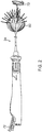
FIG. 5 is a perspective view of the reinforcement component ofFIG. 3 ; -
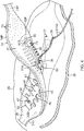
FIG. 6 is a side view of an unassembled balloon component; and -
FIG. 7 is a detail view of the distal end of the catheter ofFIG. 3 . - The following detailed description should be read with reference to the drawings, in which like elements in different drawings are identically numbered. The drawings, which are not necessarily to scale, depict selected embodiments and are not intended to limit the scope of the invention. The detailed description illustrates by way of example, not by way of limitation, the principles of the invention. This description will clearly enable one skilled in the art to make and use the invention, and describes several embodiments, adaptations, variations, alternatives and uses of the invention, including what is presently believed to be the best mode of carrying out the invention.
- As used herein, the terms "about" or "approximately" for any numerical values or ranges indicate a suitable dimensional tolerance that allows the part or collection of components to function for its intended purpose as described herein. More specifically, "about" or "approximately" may refer to the range of values ±10% of the recited value, e.g. "about 90%" may refer to the range of values from 81% to 99%. In addition, as used herein, the terms "patient," "host," "user," and "subject" refer to any human or animal subject and are not intended to limit the systems or methods to human use, although use of the subject invention in a human patient represents a preferred embodiment.
- Ablation of cardiac tissue to correct a malfunctioning heart is a well-known procedure. Typically, to successfully ablate, cardiac electropotentials need to be measured at various locations of the myocardium. In addition, temperature measurements during ablation provide data enabling the efficacy of the ablation to be measured. Typically, for an ablation procedure, the electropotentials and the temperatures are measured before, during, and after the actual ablation.
- An ablation catheter may include a lumen, and a balloon may be deployed through the catheter lumen. A multi-layer flexible metal structure is attached to an exterior wall or membrane of the balloon. The structure comprises a plurality of electrode groups arranged circumferentially about the longitudinal axis, where each electrode group comprises multiple ablation electrodes, typically arranged longitudinally.
- Each electrode group may also include at least one micro-electrode that is insulated physically and electrically from the ablation electrodes in its group.
- Each electrode group may also include at least a thermocouple.
- In some embodiments, each electrode group has a micro-electrode and a thermocouple formed at a common location.
- Using a single catheter, with the three functionalities of ability to perform ablation, electropotential measurement, and temperature measurement, simplifies cardiac ablation procedures.
-
FIG. 1 is a schematic illustration of an invasive medicalprocedure using apparatus 12, according to an embodiment. The procedure is performed by a medical professional 14, and, by way of example, the procedure in the description hereinbelow is assumed to comprise ablation of a portion of amyocardium 16 of the heart of ahuman patient 18. However, it is understood that embodiments disclosed herein are not merely applicable to this specific procedure and may include substantially any procedure on biological tissue or on non-biological materials. - To perform the ablation, medical professional 14 inserts a
probe 20 into asheath 21 that has been pre-positioned in a lumen of the patient.Sheath 21 is positioned so that adistal end 22 ofprobe 20 enters the heart of the patient. A diagnostic/therapeutic catheter 24 (e.g., a balloon catheter), which is described in more detail below with reference toFIG. 2 , is deployed through alumen 23 of theprobe 20 and exits from a distal end of theprobe 20. - As shown in
FIG. 1 ,apparatus 12 is controlled by asystem processor 46, which is in an operatingconsole 15 of the apparatus.Console 15 comprisescontrols 49 which are used by professional 14 to communicate with the processor. During the procedure, theprocessor 46 typically tracks a location and an orientation of thedistal end 22 of theprobe 20, using any method known in the art. For example,processor 46 may use a magnetic tracking method, wherein magnetic transmitters 25X, 25Y and 25Z external to the patient 18 generate signals in coils positioned in the distal end of theprobe 20. The CARTO® system (available from Biosense Webster, Inc. of Irvine, California) uses such a tracking method. - The software for the
processor 46 may be downloaded to the processor in electronic form, over a network, for example. Alternatively, or additionally, the software may be provided on non-transitory tangible media, such as optical, magnetic, or electronic storage media. The tracking of thedistal end 22 is may be displayed on a three-dimensional representation 60 of the heart of the patient 18 on ascreen 62. However, it may be displayed two-dimensionally, e.g., by fluoroscopy or MRI. - To operate
apparatus 12, theprocessor 46 communicates with amemory 50, which has many modules used by the processor to operate the apparatus. Thus, thememory 50 comprises atemperature module 52, anablation module 54, and an electrocardiograph (ECG)module 56, the functions of which are described below. Thememory 50 typically comprises other modules, such as a force module for measuring the force on thedistal end 22, a tracking module for operating the tracking method used by theprocessor 46, and an irrigation module allowing the processor to control irrigation provided for thedistal end 22. For simplicity, such other modules are not illustrated inFIG. 1 . The modules may comprise hardware as well as software elements. For example,module 54 may include a radio-frequency generator with at least one output or output channel, e.g., ten outputs or ten output channels. Each of the outputs may be separately and selectively activated or deactivated by a switch. That is, each switch may be disposed between the signal generator and a respective output. Thus, a generator with ten outputs would include ten switches. These outputs may each be individually coupled to electrodes on an ablation catheter, e.g., the tenelectrodes 33 onballoon 80, described in further detail below. Such an electrical connection may be achieved by establishing an electrical path between each output and each electrode. For example, each output may be connected to a corresponding electrode by one or more wires or suitable electrical connectors. Thus, in some embodiments, an electrical path may include at least one wire. In some embodiments, the electrical path may further include an electrical connector and at least a second wire. Thus,electrodes 33 may be selectively activated and deactivated with the switches to receive radiofrequency energy separately from each of the other electrodes. -
FIG. 3 is a schematic perspective view of the diagnostic/therapeutic catheter 24 in an expandable configuration in the form of a balloon in its expanded configuration, according to an embodiment. The diagnostic/therapeutic catheter 24 is supported by atubular shaft 70 having aproximal shaft portion 82 and adistal shaft end 88.Shaft 70 may include a first shaft portion and a second shaft portion disposed at least partially within the first shaft portion in a telescoping relationship therewith, such thatproximal shaft portion 82 is a portion of the first shaft portion anddistal shaft end 88 is a distal end of the second shaft. Theshaft 70 includes a hollowcentral tube 74, which permits a catheter to pass therethrough and past thedistal shaft end 88. The catheter may be a focal linear catheter or alasso catheter 72, as illustrated. Thelasso catheter 72 may be inserted into the pulmonary vein to position the diagnostic/therapeutic catheter 24 correctly with respect to the ostium prior to ablation of the ostium. The distal lasso portion of thecatheter 72 is typically formed of shape-memory retentive material such as nitinol. It is understood that the diagnostic/therapeutic catheter 24 may also be used with a linear or focal catheter 99 (as shown in broken lines inFIG. 3 ) in the PV or elsewhere in the heart. The focal catheter 99 may include a force sensor at its distal tip. Suitable force sending distal tips are disclosed inU.S. Patent No. 8,357,152, issued on January 22, 2013 to Govari et al. , titled CATHETER WITH PRESSURE SENSING, and inU.S. Patent Application 2011/0130648, to Beeckler et al., filed Nov. 30, 2009 , titled CATHETER WITH PRESSURE MEASURING TIP, the entire contents of both of which are incorporated herein by reference. Any catheter used in conjunction with the diagnostic/therapeutic catheter may have features and functions, including, for example, pressure sensing, ablation, diagnostic, e.g., navigation and pacing. - The
balloon 80 of the diagnostic/therapeutic catheter 24 has an exterior wall ormembrane 26 of a bio-compatible material, for example, formed from a plastic such as polyethylene terephthalate (PET), polyurethane, Pellethane® or PEBAX®. Theshaft 70 and thedistal shaft end 88 define alongitudinal axis 78 of theballoon 80. Theballoon 80 is deployed, in a collapsed configuration, via thelumen 23 of theprobe 20, and may be expanded to an expanded configuration after exiting from thedistal end 22 by telescoping the first shaft portion relative to the second shaft portion. Themembrane 26 of theballoon 80 is formed with irrigation pores or apertures 27 (shown inFIG. 4 ) through which the fluid (e.g., saline) can exit from the interior of theballoon 80 to outside the balloon for cooling the tissue ablation site at the ostium. WhileFIG. 2 shows fluid exiting theballoon 80 as jet streams, it is understood that the fluid may exit the balloon with any desired flow rate or pressure, including a rate where the fluid is seeping out of the balloon. - The
membrane 26 supports and carries a combined electrode and temperature sensing member which is constructed as a multi-layer flexiblecircuit electrode assembly 84. The "flex circuit electrode assembly" 84 may have many different geometric configurations. In the illustrated embodiment, the flexcircuit electrode assembly 84 has a plurality of radiating substrates or strips 30. Thesubstrates 30 are evenly distributed aboutmembrane 26 ofballoon 80. Each substrate has wider proximal portion that gradually tapers to a narrower distal portion. - Each
substrate 30 has aproximal tail 31P proximal to the wider proximal portion and adistal tail 31D distal of the narrower distal portion. Theproximal tail 31P may be tucked under and fastened to thecatheter 24 by aproximal ring 28P mounted on theproximal shaft portion 82 of theshaft 70. Thedistal tail 31D may be tucked under and fastened tocatheter 24 atdistal shaft end 88 by distal ring orcap 28D. - For simplicity, the flex
circuit electrode assembly 84 is described with respect to one of itssubstrates 30 as shown inFIG. 4 , although it is understood that following description may apply to each substrate of the assembly. The flexcircuit electrode assembly 84 includes a flexible andresilient sheet substrate 34, constructed of suitable bio-compatible materials, for example, polyimide. In some embodiments, thesheet substrate 34 has a greater heat resistance (or a higher melting temperature) compared to that of theballoon membrane 26. In some embodiments, thesubstrate 34 is constructed of a thermoset material having a decomposition temperature that is higher than the melting temperature of theballoon membrane 26 by approximately 100 degrees Celsius or more. - The
substrate 34 is formed with one or more irrigation pores orapertures 35 that are in alignment with theirrigation apertures 27 of theballoon member 26 so that fluid passing through theirrigation apertures - The
substrate 34 has a first orouter surface 36 facing away from theballoon membrane 26, and a second orinner surface 37 facing theballoon membrane 26. On itsouter surface 36, thesubstrate 34 supports and carries thecontact electrodes 33 adapted for tissue contact with the ostium. On itsinner surface 37, thesubstrate 34 supports and carries awiring electrode 38. Thecontact electrode 33 delivers RF energy to the ostium during ablation or is connected to a thermocouple junction for temperature sensing of the ostium. In the illustrated embodiment, thecontact electrode 33 has a longitudinally elongated portion 40 and a plurality of thin transversal linear portions orfingers 41 extending generally perpendicularly from each lateral side of the elongated portion 40 between enlarged proximal anddistal ends contact electrode 33 may resemble a "fishbone" but it should be noted that the invention is not limited to such configuration. In contrast to an area or "patch" ablation electrode, thefingers 41 of thecontact electrode 33 advantageously increase the circumferential or equatorial contact surface of thecontact electrode 33 with the ostium whilevoid regions 43 betweenadjacent fingers 41 advantageously allow theballoon 80 to collapse inwardly or expand radially as needed at locations along its equator. In the illustrated embodiment, thefingers 41 have different lengths, some being longer, others being shorter. For example, the plurality of fingers includes a distal finger, a proximal finger and fingers therebetween, where each of the fingers in between has a shorter adjacent finger. For example, each finger has a length different from its distal or proximal immediately adjacent neighboring finger(s) such that the length of each finger generally follows the tapered configuration of eachsubstrate 30. In the illustrated embodiment, there are 22 fingers extending across (past each lateral side of) the elongated portion 40, with the longest finger being the third finger from the enlargedproximal end 42P. In some embodiments, thecontact electrode 33 includes gold 58B with a seed layer between the gold 58B and themembrane 26. The seed layer may include titanium, tungsten, palladium, silver, or combinations thereof. - Formed within the
contact electrode 33 are one ormore exclusion zones 47, each surrounding anirrigation aperture 35 formed in thesubstrate 34. Theexclusion zones 47 are voids purposefully formed in thecontact electrode 33, as explained in detail further below, so as to avoid damage to thecontact electrode 33 during construction of theelectrode assembly 84 in accommodating theirrigation apertures 35 at their locations and in their function. - Also formed in the
contact electrode 33 are one or more conductiveblind vias 48 which are conductive or metallic formations that extend through through-holes in thesubstrate 34 and are configured as electrical conduits connecting thecontact electrode 33 on theouter surface 36 and thewiring electrode 38 on theinner surface 37. It is understood that "conductive" is used herein interchangeably with "metallic" in all relevant instances. - In the illustrated embodiment, the
contact electrode 33 measures longitudinally between about 0.1 inch and 1.0 inch, and preferably between about 0.5 inch and 0.7 inch, and more preferably about 0.57 inch, and has fourexclusion zones 47 and nineblind vias 48. - On the
inner surface 37 of thesubstrate 34, thewiring electrode 38 is generally configured as an elongated body generally similar in shape and size to the elongated portion 40 of thecontact electrode 33. Thewiring electrode 38 loosely resembles a "spine" and also functions as a spine in terms of providing a predetermined degree of longitudinal rigidity to eachsubstrate 30 of theelectrode assembly 84. Thewiring electrode 38 is positioned such that each of theblind vias 48 is in conductive contact with both thecontact electrode 33 and thewiring electrode 38. In the illustrated embodiment, the twoelectrodes blind vias 48 in conductive contact with bothelectrodes wiring electrode 38 has an inner portion of copper 57 and an outer portion of gold 58. - The
wiring electrode 38 is also formed with itsexclusion zones 59 around theirrigation apertures 35 in thesubstrate 34. Thewiring electrode 38 is further formed with solder pad portions 61, at least one active 61A, and there may be one or more inactivesolder pad portions 61B. Thesolder pad portions wiring electrode 38. In the illustrated embodiment, an activesolder pad portion 61A is formed at about a mid-location along the elongated body, and a respective inactivesolder pad portion 61B is provided at each of the enlargeddistal end 42D and the enlargedproximal end 42P. - Attached, e.g., by a
solder weld 63, to the activesolder pad portion 61A are the wire pair, e.g., a constantan wire 51 and a copper wire 53. The copper wire 53 provides a lead wire to thewiring electrode 33, and the copper wire 53 and the constantan wire 51 provide a thermocouple whose junction is atsolder weld 63. The wire pair 51/53 are passed through a through-hole 29 formed in themembrane 26. It is understood that, in other embodiments in the absence of the through-hole 29, the wire pair 51/53 may run between themembrane 26 and thesubstrate 34 and further proximally between themembrane 26 and theproximal tail 31P until the wire pair 51/53 enters thetubular shaft 70 via another through-hole (not shown) formed in the tubular shaft sidewall closer to theproximal ring 28P. - The flex
circuit electrode assembly 84, including thesubstrates 30 and thetails balloon membrane 26 such that theouter surface 36 of thesubstrate 34 is exposed and theinner surface 37 of thesubstrate 34 is affixed to theballoon membrane 26, with thewiring electrode 38 and wire pair 51/53 sandwiched between thesubstrate 34 and theballoon membrane 26. The irrigation apertures 35 in thesubstrate 34 are aligned with theirrigation apertures 27 in theballoon membrane 26. Theexclusion zones 59 in thewiring electrode 38 and theexclusion zones 47 in thecontact electrode 33 are concentrically aligned with each other, as well as with theirrigation apertures balloon 26 andsubstrate 34, respectively. - Further details on constructing a diagnostic/therapeutic catheter in accordance with the foregoing disclosure may be found in
U.S. Patent Application No. 15/360,966 , published asU.S. Patent Application Publication No. 2017/0312022 , which is incorporated by reference herein in its entirety. - Through ongoing research and product development efforts concerning the subject matter described above, Applicant has determined that
balloon 80 must be able to withstand multiple cycles of being deployed fromlumen 23 ofprobe 20 in the collapsed configuration, expanded to the expanded configuration, returned to the collapsed configuration and withdrawn intolumen 23 ofprobe 20. The number of cycles may be from about five to about twenty. That is, the connection betweensubstrate 30 andmembrane 26 ofballoon 80 and overall integrity of the assembled balloon must withstand at least five to twenty fatigue cycles and any additional frictional stresses experienced during five to twenty deployments from and five to twenty withdrawals intolumen 23. Applicant believes that there is a very small likelihood of potential delamination ofproximal tails 31P anddistal tails 31D frommembrane 26, which could arise from repeated fatiguing and has implemented a solution that would prevent, or at least significantly further lower the likelihood of, any such delamination. Applicant further determined that any such solution would need to accommodate for various design constraints, such as :1) minimizing concomitant safety concerns caused by any solution; 2) minimizing any increase to diameter of the portions ofballoon 80 upon whichdistal tails 31D andproximal tails 31P are adhered such thatballoon 80 in the collapsed configuration may be readily deployed from and withdrawn intolumen 23 with little or no increase in friction therebetween (or especially, in the extreme, avoiding a need to increase the diameter of lumen 23); 3) minimizing any increase to the stiffness ofballoon 80, which could interfere with establishing contact betweenelectrode 30 and tissue during a procedure; 4) not impeding electrical contact betweenelectrodes 33 and tissue during a procedure; and 5) minimizing an increase to the number of assembly steps. - Disclosed herein is a reinforcement or
reinforcement component 100 that assists in preventing the delamination problem without violating the design constraints.Reinforcement component 100 may have a shape like and thus conform to a proximal or distal portion ofmembrane 26. For example,reinforcement component 100 may include a portion of anunassembled catheter balloon 80, i.e., aballoon 80 that has not been assembled to any other components ofcatheter 24, such assubstrates 30. That is, aballoon 80 may have a portion separated therefrom by cuttingmembrane 26 along one of thelines 86 as seen inFIG. 6 . In embodiments whereballoon 80 is symmetric about a center line, two portions ofballoon 80 may be removed to create tworeinforcement components 100. In embodiments wheremembrane 26 is asymmetric about a center line, the distal portion thereof may be used asreinforcement component 100 fordistal tails 31D and the proximal portion thereof may be used asreinforcement component 100 forproximal tails 31P. - Thus,
reinforcement component 100 may be provided as having a horn-like (e.g., bell-mouth) shape as seen inFig. 5 .Membrane 26, withflexible circuit assembly 84 adhered thereto, may have its proximal portion disposed withinreinforcement component 100 such thatreinforcement component 100 coversproximal tails 31P or a portion thereof. Alternatively, or additionally,membrane 26, withflexible circuit assembly 84 adhered thereto, may have its distal portion disposed withinreinforcement component 100 such thatreinforcement component 100 coversdistal tails 31D or a portion thereof. Reinforcement component(s) 100 may then be adhered tomembrane 26 via e.g., epoxy, or mechanical or thermal fusion. Accordingly, the tails are sandwiched betweenballoon 80 andreinforcement component 100. In thisconfiguration reinforcement component 100 may absorb stresses caused by expanding and collapsingballoon 80, thereby reducing fatigue to the tails. Further, the tails are shielded from friction betweenreinforcement component 100 and walls oflumen 23, that would otherwise exist between the tails and the walls oflumen 23 during deployment and withdrawal, thereby further reducing stresses upon the tails. - In further embodiments, the likelihood of delamination may be further reduced by supporting one or more of the tails (e.g., all of the tails) with a length of filament between
membrane 26 and arespective tail - By virtue of the embodiments illustrated and described herein, applicant has devised a method of using a diagnostic/therapeutic catheter having a balloon upon which is disposed various components suitable for ablating tissues, the method including repeated steps that may stress connections between the balloon and the catheter. Specifically, a catheter, such as the one heretofore described (e.g., catheter 24) may be received by a user. The user may deploy the balloon from the catheter, expand the balloon, collapse the balloon, and withdraw the balloon into the catheter. These steps may be repeated between five to fifteen, e.g., ten times. Moreover, the user may use electrodes disposed on the balloon to ablate tissue, typically between the steps of expanding and collapsing the balloon.
- Any of the examples or embodiments described herein may include various other features in addition to or in lieu of those described above. The teachings, expressions, embodiments, examples, etc. described herein should not be viewed in isolation relative to each other. Various suitable ways in which the teachings herein may be combined should be clear to those skilled in the art in view of the teachings herein.
- Having shown and described exemplary embodiments of the subject matter contained herein, further adaptations of the methods and systems described herein may be accomplished by appropriate modifications without departing from the scope of the claims. In addition, where methods and steps described above indicate certain events occurring in certain order, it is intended that certain steps do not have to be performed in the order described but, in any order as long as the steps allow the embodiments to function for their intended purposes. Therefore, to the extent there are variations of the invention, which are within the spirit of the disclosure or equivalent to the inventions found in the claims, it is the intent that this patent will cover those variations as well. Some such modifications should be apparent to those skilled in the art. For instance, the examples, embodiments, geometries, materials, dimensions, ratios, steps, and the like discussed above are illustrative. Accordingly, the claims should not be limited to the specific details of structure and operation set forth in the written description and drawings.
Claims (21)
- A catheter balloon, comprising:a membrane including a proximal end and a distal end;a plurality of substrates, each including a plurality of tails, disposed about the membrane;and a reinforcement disposed over at least some of the plurality of tails and attached to the membrane.
- A catheter, comprising:a shaft having a first shaft portion and second shaft portion at least partially disposed within the first shaft portion;a catheter balloon having a membrane including a proximal end and a distal end, the proximal end connected to the first shaft portion and the distal end connected to the second shaft portion;a plurality of substrates, each including a plurality of tails, disposed about the membrane;and a reinforcement disposed over at least some of the plurality of tails and attached to the membrane.
- The catheter of claim 2, further comprising a ring disposed about at least a portion of the reinforcement.
- The catheter balloon of claim 1 or the catheter of claim 2, in which the reinforcement comprises a portion of an unassembled catheter balloon.
- The catheter balloon of claim 1 or the catheter of claim 4, in which the reinforcement has a horn-like shape.
- The catheter balloon or the catheter of claim 5, in which the membrane comprises polyethylene terephthalate, polyurethane, Pellethane, or PEBAX.
- The catheter balloon of claim 1 or the catheter of claim 3, in which the plurality of tails includes a plurality of proximal tails and a plurality of distal tails, the plurality of proximal tails being disposed proximate to the proximal end of the balloon and the plurality of distal tails being disposed proximate to the distal end of the balloon.
- The catheter balloon or the catheter of claim 7, in which the reinforcement is disposed over the plurality of proximal tails.
- The catheter balloon or the catheter of claim 7, in which the reinforcement is disposed over the plurality of distal tails.
- The catheter balloon or the catheter of claim 9, in which the reinforcement is a first reinforcement and the catheter balloon further comprises a second reinforcement disposed over the plurality of proximal tails.
- The catheter of claim 10, in which the ring is a first ring disposed about the first reinforcement and the balloon further comprises a second ring disposed about at least a portion of the second reinforcement.
- The catheter of claim 11, in which the second shaft portion is disposed within the first shaft portion in a telescoping relationship.
- The catheter balloon of claim 10, in which the first reinforcement is symmetric with the second reinforcement.
- The catheter balloon of claim 13, in which the membrane further includes irrigation apertures disposed therethrough.
- The catheter balloon of claim 13 or the catheter of claim 11, further comprising a plurality of ablation electrodes.
- The catheter balloon or the catheter of claim 15, in which at least one of the ablation electrodes is disposed on each of the substrates.
- The catheter of claim 15, further comprising a lead wire at least partially disposed in the shaft and in the balloon, and connected to at least one of the ablation electrodes.
- The catheter balloon of claim 13 or the catheter of claim 11, further comprising a filament disposed between the membrane and at least one of the plurality of tails.
- The catheter balloon of claim 18, in which the filament comprises a liquid-crystal polymer.
- The catheter of claim 18, in which the filament comprises one of an ultra-high molecular weight polymer or a liquid-crystal polymer.
- The catheter balloon of claim 19 or the catheter of claim 20, where the liquid-crystal polymer comprises Vectran.
Applications Claiming Priority (2)
| Application Number | Priority Date | Filing Date | Title |
|---|---|---|---|
| US201862692439P | 2018-06-29 | 2018-06-29 | |
| US16/432,392 US12102781B2 (en) | 2018-06-29 | 2019-06-05 | Reinforcement for irrigated electrophysiology balloon catheter with flexible-circuit electrodes |
Publications (3)
| Publication Number | Publication Date |
|---|---|
| EP3586778A1 true EP3586778A1 (en) | 2020-01-01 |
| EP3586778C0 EP3586778C0 (en) | 2026-02-25 |
| EP3586778B1 EP3586778B1 (en) | 2026-02-25 |
Family
ID=67137678
Family Applications (1)
| Application Number | Title | Priority Date | Filing Date |
|---|---|---|---|
| EP19183327.6A Active EP3586778B1 (en) | 2018-06-29 | 2019-06-28 | Reinforcement for irrigated electrophysiology balloon catheter with flexible-circuit electrodes |
Country Status (11)
| Country | Link |
|---|---|
| US (1) | US12102781B2 (en) |
| EP (1) | EP3586778B1 (en) |
| JP (1) | JP7451100B2 (en) |
| KR (1) | KR20200003353A (en) |
| CN (2) | CN211911786U (en) |
| AU (1) | AU2019204311A1 (en) |
| BR (1) | BR102019013384A2 (en) |
| CA (1) | CA3048279A1 (en) |
| IL (1) | IL267361B2 (en) |
| MX (1) | MX2019007868A (en) |
| RU (1) | RU2019120055A (en) |
Cited By (22)
| Publication number | Priority date | Publication date | Assignee | Title |
|---|---|---|---|---|
| WO2021116773A1 (en) * | 2019-12-09 | 2021-06-17 | Biosense Webster (Israel) Ltd. | Irreversible-electroporation (ire) balloon catheter with membrane-insulated high-voltage balloon wires |
| EP3960105A1 (en) * | 2020-08-13 | 2022-03-02 | Biosense Webster (Israel) Ltd | Applying bipolar ablation energy between shorted electrode groups |
| EP4205677A1 (en) * | 2021-08-27 | 2023-07-05 | Biosense Webster (Israel) Ltd. | Reinforcement and stress relief for an irrigated electrophysiology balloon catheter with flexible-circuit electrodes |
| US11957852B2 (en) | 2021-01-14 | 2024-04-16 | Biosense Webster (Israel) Ltd. | Intravascular balloon with slidable central irrigation tube |
| US11963715B2 (en) | 2016-11-23 | 2024-04-23 | Biosense Webster (Israel) Ltd. | Balloon-in-balloon irrigation balloon catheter |
| US11974803B2 (en) | 2020-10-12 | 2024-05-07 | Biosense Webster (Israel) Ltd. | Basket catheter with balloon |
| US12029545B2 (en) | 2017-05-30 | 2024-07-09 | Biosense Webster (Israel) Ltd. | Catheter splines as location sensors |
| US12042246B2 (en) | 2016-06-09 | 2024-07-23 | Biosense Webster (Israel) Ltd. | Multi-function conducting elements for a catheter |
| US12102781B2 (en) | 2018-06-29 | 2024-10-01 | Biosense Webster (Israel) Ltd. | Reinforcement for irrigated electrophysiology balloon catheter with flexible-circuit electrodes |
| US12137967B2 (en) | 2019-11-12 | 2024-11-12 | Biosense Webster (Israel) Ltd. | Accurate positioning and shape visualization of balloon catheter ablation tags |
| US12161400B2 (en) | 2019-10-04 | 2024-12-10 | Biosense Webster (Israel) Ltd. | Identifying pulmonary vein occlusion by dimension deformations of balloon catheter |
| US12186013B2 (en) | 2021-02-18 | 2025-01-07 | Biosense Webster (Israel) Ltd. | Detection of balloon catheter tissue contact using optical measurement |
| US12239364B2 (en) | 2020-10-07 | 2025-03-04 | Biosense Webster (Israel) Ltd. | Printed proximal electrodes of an expandable catheter for use as a common electrode |
| US12268436B2 (en) | 2018-09-14 | 2025-04-08 | Biosense Webster (Israel) Ltd. | Systems and methods of ablating cardiac tissue |
| US12369975B2 (en) | 2019-09-12 | 2025-07-29 | Biosense Webster (Israel) Ltd. | Balloon catheter with force sensor |
| US12369974B2 (en) | 2019-10-10 | 2025-07-29 | Biosense Webster (Israel) Ltd. | Touch indication of balloon-catheter ablation electrode via balloon surface temperature measurement |
| US12458436B2 (en) | 2018-07-30 | 2025-11-04 | Biosense Webster (Israel) Ltd. | Flexible-circuit tip for a split-tip catheter |
| US12544128B2 (en) | 2020-10-30 | 2026-02-10 | Biosense Webster (Israel) Ltd. | Balloon catheter with split electrodes |
| US12551270B2 (en) | 2022-06-23 | 2026-02-17 | Biosense Webster (Israel) Ltd. | Graphical contact quality indicator for balloon catheter navigation |
| US12558154B2 (en) | 2020-08-14 | 2026-02-24 | Biosense Webster (Israel) Ltd. | Balloon catheter having ablation and return electrodes |
| USD1115794S1 (en) | 2022-06-23 | 2026-03-03 | Biosense Webster (Israel) Ltd. | Display screen with GUI for contact quality indicator of expandable end effectors in computer-aided electrophysiology navigation |
| US12616515B2 (en) | 2019-08-27 | 2026-05-05 | Biosense Webster (Israel) Ltd. | Estimation of electrode-tissue contact using stem and edge electrodes |
Families Citing this family (5)
| Publication number | Priority date | Publication date | Assignee | Title |
|---|---|---|---|---|
| US11534239B2 (en) | 2014-12-22 | 2022-12-27 | Biosense Webster (Israel) Ltd. | Systems and method or uses of ablating cardiac tissue |
| US12082875B2 (en) | 2020-09-24 | 2024-09-10 | Biosense Webster (Israel) Ltd | Balloon catheter having a coil for sensing tissue temperature and position of the balloon |
| CA3223384A1 (en) | 2021-07-05 | 2023-01-12 | Jordan Pollack | Vessel blockage passing |
| US12594405B2 (en) | 2021-07-19 | 2026-04-07 | Otsuka Medical Devices Co., Ltd. | Catheter having compliant balloon |
| CN118304549B (en) * | 2024-06-07 | 2024-08-09 | 鹏瓴医疗科技(杭州)有限公司 | Prostate expands and splits pipe |
Citations (6)
| Publication number | Priority date | Publication date | Assignee | Title |
|---|---|---|---|---|
| US6012457A (en) * | 1997-07-08 | 2000-01-11 | The Regents Of The University Of California | Device and method for forming a circumferential conduction block in a pulmonary vein |
| US20030018327A1 (en) * | 2001-07-20 | 2003-01-23 | Csaba Truckai | Systems and techniques for lung volume reduction |
| US20110130648A1 (en) | 2009-11-30 | 2011-06-02 | Christopher Thomas Beeckler | Catheter with pressure measuring tip |
| US8357152B2 (en) | 2007-10-08 | 2013-01-22 | Biosense Webster (Israel), Ltd. | Catheter with pressure sensing |
| US20170042614A1 (en) * | 2008-11-11 | 2017-02-16 | Amr Salahieh | Ablation catheters |
| US20170312022A1 (en) | 2016-04-28 | 2017-11-02 | Biosense Webster (Israel) Ltd. | Irrigated balloon catheter with flexible circuit electrode assembly |
Family Cites Families (256)
| Publication number | Priority date | Publication date | Assignee | Title |
|---|---|---|---|---|
| FR1344459A (en) | 1962-10-18 | 1963-11-29 | Method and apparatus for the electrical study of living organisms | |
| US4276874A (en) | 1978-11-15 | 1981-07-07 | Datascope Corp. | Elongatable balloon catheter |
| US4232676A (en) | 1978-11-16 | 1980-11-11 | Corning Glass Works | Surgical cutting instrument |
| US4587975A (en) | 1984-07-02 | 1986-05-13 | Cardiac Pacemakers, Inc. | Dimension sensitive angioplasty catheter |
| US4709698A (en) | 1986-05-14 | 1987-12-01 | Thomas J. Fogarty | Heatable dilation catheter |
| EP0249823B1 (en) | 1986-06-16 | 1991-12-18 | Pacesetter AB | Device for the control of a heart pacer using impedance measurement at body tissues |
| US5178957A (en) | 1989-05-02 | 1993-01-12 | Minnesota Mining And Manufacturing Company | Noble metal-polymer composites and flexible thin-film conductors prepared therefrom |
| JP2891032B2 (en) | 1993-03-15 | 1999-05-17 | 日本ゼオン株式会社 | Balloon catheter |
| US5860974A (en) | 1993-07-01 | 1999-01-19 | Boston Scientific Corporation | Heart ablation catheter with expandable electrode and method of coupling energy to an electrode on a catheter shaft |
| US5391199A (en) | 1993-07-20 | 1995-02-21 | Biosense, Inc. | Apparatus and method for treating cardiac arrhythmias |
| US20020002369A1 (en) | 1993-08-23 | 2002-01-03 | Hood Larry L. | Method and apparatus for modifying visual acuity by moving a focal point of energy within a cornea |
| US5582609A (en) | 1993-10-14 | 1996-12-10 | Ep Technologies, Inc. | Systems and methods for forming large lesions in body tissue using curvilinear electrode elements |
| US5797903A (en) | 1996-04-12 | 1998-08-25 | Ep Technologies, Inc. | Tissue heating and ablation systems and methods using porous electrode structures with electrically conductive surfaces |
| US5429617A (en) | 1993-12-13 | 1995-07-04 | The Spectranetics Corporation | Radiopaque tip marker for alignment of a catheter within a body |
| US5584830A (en) | 1994-03-30 | 1996-12-17 | Medtronic Cardiorhythm | Method and system for radiofrequency ablation of cardiac tissue |
| EP0767628B1 (en) | 1994-06-27 | 2004-01-14 | Boston Scientific Limited | Non-linear control systems for heating and ablating body tissue |
| JP3708121B2 (en) | 1994-08-19 | 2005-10-19 | バイオセンス・インコーポレイテッド | Diagnosis and handling of medical equipment and video system |
| US6690963B2 (en) | 1995-01-24 | 2004-02-10 | Biosense, Inc. | System for determining the location and orientation of an invasive medical instrument |
| NL1001890C2 (en) | 1995-12-13 | 1997-06-17 | Cordis Europ | Catheter with plate-shaped electrode array. |
| CA2243595A1 (en) | 1996-01-19 | 1997-07-24 | Ep Technologies, Inc. | Multi-function electrode structures for electrically analyzing and heating body tissue |
| IL125757A (en) | 1996-02-15 | 2003-09-17 | Biosense Inc | Medical procedures and apparatus using intrabody probes |
| IL125761A (en) | 1996-02-15 | 2005-05-17 | Biosense Inc | Independently positionable transducers for location system |
| US6325777B1 (en) | 1996-05-20 | 2001-12-04 | Medtronic Percusurge, Inc. | Low profile catheter valve and inflation adaptor |
| US6719755B2 (en) | 1996-10-22 | 2004-04-13 | Epicor Medical, Inc. | Methods and devices for ablation |
| US5971983A (en) | 1997-05-09 | 1999-10-26 | The Regents Of The University Of California | Tissue ablation device and method of use |
| US6024740A (en) | 1997-07-08 | 2000-02-15 | The Regents Of The University Of California | Circumferential ablation device assembly |
| US6500174B1 (en) | 1997-07-08 | 2002-12-31 | Atrionix, Inc. | Circumferential ablation device assembly and methods of use and manufacture providing an ablative circumferential band along an expandable member |
| US6652515B1 (en) | 1997-07-08 | 2003-11-25 | Atrionix, Inc. | Tissue ablation device assembly and method for electrically isolating a pulmonary vein ostium from an atrial wall |
| US6966908B2 (en) | 1997-07-08 | 2005-11-22 | Atrionix, Inc. | Tissue ablation device assembly and method for electrically isolating a pulmonary vein ostium from an atrial wall |
| US6997925B2 (en) | 1997-07-08 | 2006-02-14 | Atrionx, Inc. | Tissue ablation device assembly and method for electrically isolating a pulmonary vein ostium from an atrial wall |
| US6164283A (en) | 1997-07-08 | 2000-12-26 | The Regents Of The University Of California | Device and method for forming a circumferential conduction block in a pulmonary vein |
| JP3857788B2 (en) | 1997-09-01 | 2006-12-13 | テルモ株式会社 | Cardiovascular information measurement system |
| US6239724B1 (en) | 1997-12-30 | 2001-05-29 | Remon Medical Technologies, Ltd. | System and method for telemetrically providing intrabody spatial position |
| US6142993A (en) | 1998-02-27 | 2000-11-07 | Ep Technologies, Inc. | Collapsible spline structure using a balloon as an expanding actuator |
| US6093185A (en) | 1998-03-05 | 2000-07-25 | Scimed Life Systems, Inc. | Expandable PMR device and method |
| US6042580A (en) | 1998-05-05 | 2000-03-28 | Cardiac Pacemakers, Inc. | Electrode having composition-matched, common-lead thermocouple wire for providing multiple temperature-sensitive junctions |
| US6522930B1 (en) | 1998-05-06 | 2003-02-18 | Atrionix, Inc. | Irrigated ablation device assembly |
| US6226542B1 (en) | 1998-07-24 | 2001-05-01 | Biosense, Inc. | Three-dimensional reconstruction of intrabody organs |
| US6301496B1 (en) | 1998-07-24 | 2001-10-09 | Biosense, Inc. | Vector mapping of three-dimensionally reconstructed intrabody organs and method of display |
| US6123718A (en) | 1998-11-02 | 2000-09-26 | Polymerex Medical Corp. | Balloon catheter |
| US6171275B1 (en) | 1998-12-03 | 2001-01-09 | Cordis Webster, Inc. | Irrigated split tip electrode catheter |
| US6380957B1 (en) | 1998-12-15 | 2002-04-30 | International Business Machines Corporation | Method of controlling view of large expansion tree |
| US6986744B1 (en) | 1999-02-02 | 2006-01-17 | Transonic Systems, Inc. | Method and apparatus for determining blood flow during a vascular corrective procedure |
| US6702811B2 (en) | 1999-04-05 | 2004-03-09 | Medtronic, Inc. | Ablation catheter assembly with radially decreasing helix and method of use |
| EP1790304B1 (en) | 1999-05-11 | 2016-08-31 | Atrionix, Inc. | Tissue ablation system including a balloon anchor wire |
| US7935108B2 (en) | 1999-07-14 | 2011-05-03 | Cardiofocus, Inc. | Deflectable sheath catheters |
| US6471693B1 (en) | 1999-09-10 | 2002-10-29 | Cryocath Technologies Inc. | Catheter and system for monitoring tissue contact |
| US7020400B2 (en) | 1999-12-24 | 2006-03-28 | Altera Corporation | Multi-wavelength optical communication system |
| US6892091B1 (en) | 2000-02-18 | 2005-05-10 | Biosense, Inc. | Catheter, method and apparatus for generating an electrical map of a chamber of the heart |
| US6546935B2 (en) | 2000-04-27 | 2003-04-15 | Atricure, Inc. | Method for transmural ablation |
| DE60105032T2 (en) | 2000-07-13 | 2005-08-18 | Merck Patent Gmbh | CHIRAL COMPOUNDS III |
| US6656174B1 (en) | 2000-07-20 | 2003-12-02 | Scimed Life Systems, Inc. | Devices and methods for creating lesions in blood vessels without obstructing blood flow |
| US6484118B1 (en) | 2000-07-20 | 2002-11-19 | Biosense, Inc. | Electromagnetic position single axis system |
| JP2004520865A (en) | 2000-07-25 | 2004-07-15 | リタ メディカル システムズ インコーポレイテッド | Apparatus for tumor detection and treatment using localized impedance measurements |
| EP1351618B1 (en) | 2001-01-11 | 2006-11-02 | C.R. Bard, Inc. | Ablation catheter |
| US6732734B2 (en) | 2001-04-27 | 2004-05-11 | Kuraray Co., Ltd. | Pilot balloon for balloon catheters |
| USD462389S1 (en) | 2001-04-27 | 2002-09-03 | Marie R. Provence | Teaching aid for learning to tell time |
| DE60203806T2 (en) | 2001-08-31 | 2005-10-06 | Boston Scientific Ltd., St. Michael | PERCUTANEOUS PRINGLE OCCLUSION DEVICE |
| US6741878B2 (en) | 2001-12-14 | 2004-05-25 | Biosense Webster, Inc. | Basket catheter with improved expansion mechanism |
| US7729742B2 (en) | 2001-12-21 | 2010-06-01 | Biosense, Inc. | Wireless position sensor |
| US6814733B2 (en) | 2002-01-31 | 2004-11-09 | Biosense, Inc. | Radio frequency pulmonary vein isolation |
| US6997924B2 (en) | 2002-09-17 | 2006-02-14 | Biosense Inc. | Laser pulmonary vein isolation |
| US20040068178A1 (en) | 2002-09-17 | 2004-04-08 | Assaf Govari | High-gradient recursive locating system |
| JP2006501957A (en) | 2002-10-04 | 2006-01-19 | クック ウロロジカル インコーポレイテッド | Hard extraction device with wire basket |
| US7156816B2 (en) | 2002-11-26 | 2007-01-02 | Biosense, Inc. | Ultrasound pulmonary vein isolation |
| US6893433B2 (en) | 2002-12-11 | 2005-05-17 | Cryocor, Inc. | System and method for performing a single step cryoablation |
| WO2004073505A2 (en) | 2003-02-20 | 2004-09-02 | Prorhythm, Inc. | Cardiac ablation devices |
| US7293562B2 (en) | 2003-03-27 | 2007-11-13 | Cierra, Inc. | Energy based devices and methods for treatment of anatomic tissue defects |
| JP2005052424A (en) | 2003-08-05 | 2005-03-03 | Matsushita Electric Ind Co Ltd | Ultrasonic diagnostic equipment |
| US7682521B2 (en) | 2003-08-22 | 2010-03-23 | The Regents Of The University Of Colorado | Aligned liquid crystal thin films and glasses |
| US8292943B2 (en) | 2003-09-03 | 2012-10-23 | Bolton Medical, Inc. | Stent graft with longitudinal support member |
| US20050059862A1 (en) | 2003-09-12 | 2005-03-17 | Scimed Life Systems, Inc. | Cannula with integrated imaging and optical capability |
| DE202004021947U1 (en) * | 2003-09-12 | 2013-05-13 | Vessix Vascular, Inc. | Selectable eccentric remodeling and / or ablation of atherosclerotic material |
| US7435248B2 (en) | 2003-09-26 | 2008-10-14 | Boston Scientific Scimed, Inc. | Medical probes for creating and diagnosing circumferential lesions within or around the ostium of a vessel |
| US7695491B2 (en) | 2003-12-01 | 2010-04-13 | Ev3 Inc. | Rapid exchange catheters with tandem lumens |
| JP4391221B2 (en) | 2003-12-22 | 2009-12-24 | 有限会社日本エレクテル | High frequency heating balloon catheter |
| US8460286B2 (en) | 2004-01-16 | 2013-06-11 | St. Jude Medical, Atrial Fibrillation Division, Inc. | Conforming electrode |
| US9713730B2 (en) | 2004-09-10 | 2017-07-25 | Boston Scientific Scimed, Inc. | Apparatus and method for treatment of in-stent restenosis |
| US7914487B2 (en) * | 2004-10-15 | 2011-03-29 | Futurematrix Interventional, Inc. | Non-compliant medical balloon having braided or knitted reinforcement |
| MX2007005891A (en) | 2004-11-15 | 2007-11-23 | Johnson & Johnson | Catheter with microfabricated temperature sensing. |
| US20060135953A1 (en) | 2004-12-22 | 2006-06-22 | Wlodzimierz Kania | Tissue ablation system including guidewire with sensing element |
| DE102005012739B4 (en) | 2005-03-19 | 2010-09-16 | MAX-PLANCK-Gesellschaft zur Förderung der Wissenschaften e.V. | Method for producing spatial fine structures |
| US7195612B2 (en) | 2005-03-31 | 2007-03-27 | Gordis Corporation | Esophageal balloon catheter with visual marker |
| US7442190B2 (en) | 2005-05-13 | 2008-10-28 | Cryocath Technologies Inc. | Contact assessment of balloon catheters |
| EP1895927A4 (en) | 2005-06-20 | 2011-03-09 | Medtronic Ablation Frontiers | Ablation catheter |
| US7536218B2 (en) | 2005-07-15 | 2009-05-19 | Biosense Webster, Inc. | Hybrid magnetic-based and impedance-based position sensing |
| US7756576B2 (en) | 2005-08-26 | 2010-07-13 | Biosense Webster, Inc. | Position sensing and detection of skin impedance |
| CA2621657C (en) | 2005-09-21 | 2014-06-17 | Surmodics, Inc. | In situ occluding compositions comprising natural biodegradable polysaccharides polymerized by a redox pair |
| US8696656B2 (en) | 2005-11-18 | 2014-04-15 | Medtronic Cryocath Lp | System and method for monitoring bioimpedance and respiration |
| US7842031B2 (en) | 2005-11-18 | 2010-11-30 | Medtronic Cryocath Lp | Bioimpedance measurement system and method |
| US8048032B2 (en) | 2006-05-03 | 2011-11-01 | Vascular Solutions, Inc. | Coaxial guide catheter for interventional cardiology procedures |
| US8677280B2 (en) | 2006-05-18 | 2014-03-18 | Ubiquity Broadcasting Corporation | Sprocket shaped user interface for navigating a dynamic collection of information |
| US20070287994A1 (en) | 2006-06-12 | 2007-12-13 | Pankaj Amrit Patel | Endoscopically Introducible Expandable Bipolar Probe |
| US20100114269A1 (en) | 2006-06-28 | 2010-05-06 | Medtronic Cryocath Lp | Variable geometry balloon catheter and method |
| US8694076B2 (en) | 2006-07-06 | 2014-04-08 | Boston Scientific Scimed, Inc. | Electroactive polymer radiopaque marker |
| US20080051707A1 (en) * | 2006-08-25 | 2008-02-28 | Phan Christopher U | Apparatus and methods for use of expandable members in surgical applications |
| US7691080B2 (en) | 2006-09-21 | 2010-04-06 | Mercator Medsystems, Inc. | Dual modulus balloon for interventional procedures |
| US8728073B2 (en) * | 2006-10-10 | 2014-05-20 | Biosense Webster, Inc. | Multi-region staged inflation balloon |
| ES2407329T3 (en) | 2006-10-18 | 2013-06-12 | Vessix Vascular, Inc. | System to induce desirable temperature effects on body tissue |
| US7993537B2 (en) | 2007-02-23 | 2011-08-09 | GM Global Technology Operations LLC | Method for improving adhesion between a shape memory alloy and a polymer |
| US8764742B2 (en) | 2007-04-04 | 2014-07-01 | St. Jude Medical, Atrial Fibrillation Division, Inc. | Irrigated catheter |
| US8496653B2 (en) | 2007-04-23 | 2013-07-30 | Boston Scientific Scimed, Inc. | Thrombus removal |
| US8641704B2 (en) | 2007-05-11 | 2014-02-04 | Medtronic Ablation Frontiers Llc | Ablation therapy system and method for treating continuous atrial fibrillation |
| US20090270850A1 (en) | 2007-06-20 | 2009-10-29 | Tea Time Partners, L.P., Organized In Texas | Devices and methods for the ablation of tissue in the lateral direction |
| US9283034B2 (en) | 2007-09-26 | 2016-03-15 | Retrovascular, Inc. | Recanalization system using radiofrequency energy |
| JP2009089806A (en) | 2007-10-05 | 2009-04-30 | Asahi Intecc Co Ltd | Balloon catheter |
| US9289141B2 (en) | 2007-10-12 | 2016-03-22 | Micropen Technologies Corporation | Apparatus and methods for the measurement of cardiac output |
| US9101431B2 (en) | 2007-11-01 | 2015-08-11 | Stephen B. Murphy | Guide for acetabular component positioning |
| US9717501B2 (en) | 2007-11-21 | 2017-08-01 | St. Jude Medical, Atrial Fibrillation Division, Inc. | Methods and systems for occluding vessels during cardiac ablation including optional electroanatomical guidance |
| US9126023B1 (en) | 2007-12-14 | 2015-09-08 | Gmedelaware 2 Llc | Balloon expandable cement director and related methods |
| US20090163890A1 (en) | 2007-12-20 | 2009-06-25 | Acclarent, Inc. | Method and System for Accessing, Diagnosing and Treating Target Tissue Regions Within the Middle Ear and the Eustachian Tube |
| US8103327B2 (en) | 2007-12-28 | 2012-01-24 | Rhythmia Medical, Inc. | Cardiac mapping catheter |
| JP2009261609A (en) | 2008-04-24 | 2009-11-12 | Fujinon Corp | Treatment instrument for endoscope |
| WO2010033266A2 (en) | 2008-05-02 | 2010-03-25 | Battelle Memorial Institute | Lightweight blast mitigating composite panel |
| DE102008062021A1 (en) | 2008-08-18 | 2010-03-04 | Epcos Ag | Piezo actuator in multilayer construction |
| JP4649506B2 (en) | 2008-09-16 | 2011-03-09 | 有限会社日本エレクテル | High frequency heating balloon catheter |
| US9545216B2 (en) | 2011-08-05 | 2017-01-17 | Mc10, Inc. | Catheter balloon methods and apparatus employing sensing elements |
| JP5342844B2 (en) | 2008-10-09 | 2013-11-13 | Hoya株式会社 | Endoscopic high-frequency snare |
| US11376061B2 (en) * | 2008-11-11 | 2022-07-05 | Covidien Lp | Energy delivery device and methods of use |
| US8295902B2 (en) | 2008-11-11 | 2012-10-23 | Shifamed Holdings, Llc | Low profile electrode assembly |
| WO2013154776A2 (en) | 2012-04-13 | 2013-10-17 | Covidien Lp | Energy delivery device and methods of use |
| US20100160906A1 (en) | 2008-12-23 | 2010-06-24 | Asthmatx, Inc. | Expandable energy delivery devices having flexible conductive elements and associated systems and methods |
| WO2010079494A1 (en) * | 2009-01-12 | 2010-07-15 | Angioslide Ltd. | Balloon and catheter system and methods for making and use thereof |
| US20100256629A1 (en) | 2009-04-06 | 2010-10-07 | Voyage Medical, Inc. | Methods and devices for treatment of the ostium |
| US8551096B2 (en) | 2009-05-13 | 2013-10-08 | Boston Scientific Scimed, Inc. | Directional delivery of energy and bioactives |
| US9754025B2 (en) | 2009-08-13 | 2017-09-05 | TunesMap Inc. | Analyzing captured sound and seeking a match based on an acoustic fingerprint for temporal and geographic presentation and navigation of linked cultural, artistic, and historic content |
| US9445859B2 (en) | 2010-01-29 | 2016-09-20 | Medtronic Cryocath Lp | Multifunctional ablation device |
| CN102905639B (en) | 2010-04-06 | 2015-05-06 | 赫莱拉公司 | Systems and methods for lung treatment |
| CA2797130A1 (en) | 2010-05-12 | 2011-11-17 | Shifamed Holdings, Llc | Low profile electrode assembly |
| US9655677B2 (en) | 2010-05-12 | 2017-05-23 | Shifamed Holdings, Llc | Ablation catheters including a balloon and electrodes |
| US9744339B2 (en) | 2010-05-12 | 2017-08-29 | Circa Scientific, Llc | Apparatus for manually manipulating hollow organs |
| US9173705B2 (en) | 2010-05-13 | 2015-11-03 | Ncontact Surgical, Inc. | Subxyphoid epicardial ablation |
| US20110295247A1 (en) | 2010-05-28 | 2011-12-01 | Hansen Medical, Inc. | System and method for automated minimally invasive therapy using radiometry |
| JP5615073B2 (en) | 2010-07-20 | 2014-10-29 | オムロンヘルスケア株式会社 | measuring device |
| US9463062B2 (en) | 2010-07-30 | 2016-10-11 | Boston Scientific Scimed, Inc. | Cooled conductive balloon RF catheter for renal nerve ablation |
| US8903473B2 (en) | 2010-09-15 | 2014-12-02 | Medtronic, Inc. | Radiopaque markers for implantable medical devices |
| AU2011236083A1 (en) | 2010-10-20 | 2012-05-10 | Maria G. Aboytes | Catheter apparatuses having expandable mesh structures for renal neuromodulation and associated systems and methods |
| US9089350B2 (en) | 2010-11-16 | 2015-07-28 | Boston Scientific Scimed, Inc. | Renal denervation catheter with RF electrode and integral contrast dye injection arrangement |
| US20120130646A1 (en) | 2010-11-19 | 2012-05-24 | Lifescan, Inc. | Analyte testing method and system with high and low analyte trends notification |
| US11246653B2 (en) | 2010-12-07 | 2022-02-15 | Boaz Avitall | Catheter systems for cardiac arrhythmia ablation |
| US8998893B2 (en) | 2010-12-07 | 2015-04-07 | Boaz Avitall | Catheter systems for cardiac arrhythmia ablation |
| US9895517B2 (en) | 2011-01-18 | 2018-02-20 | Loma Vista Medical, Inc. | Inflatable medical devices |
| US20120191083A1 (en) | 2011-01-20 | 2012-07-26 | Hansen Medical, Inc. | System and method for endoluminal and translumenal therapy |
| US8647358B2 (en) | 2011-01-21 | 2014-02-11 | Obalon Therapeutics Inc. | Intragastric device |
| US8974450B2 (en) | 2011-02-03 | 2015-03-10 | Covidien Lp | System and method for ablation procedure monitoring using electrodes |
| AU2012225250B2 (en) | 2011-03-10 | 2016-12-08 | Enchannel Medical, Ltd. | Device and method for the geometric determination of electrical dipole densities on the cardiac wall |
| US20140227437A1 (en) | 2011-05-23 | 2014-08-14 | California Institute Of Technology | Accommodating intraocular lens |
| US8975107B2 (en) | 2011-06-16 | 2015-03-10 | Infineon Techologies Ag | Method of manufacturing a semiconductor device comprising a membrane over a substrate by forming a plurality of features using local oxidation regions |
| US9220433B2 (en) | 2011-06-30 | 2015-12-29 | Biosense Webster (Israel), Ltd. | Catheter with variable arcuate distal section |
| CN106823131B (en) | 2011-09-30 | 2019-12-20 | 柯惠有限合伙公司 | Energy transfer device and method of use |
| US8498686B2 (en) | 2011-10-04 | 2013-07-30 | Biosense Webster (Israel), Ltd. | Mapping catheter with spiral electrode assembly |
| DE112012004146T5 (en) * | 2011-10-05 | 2014-11-06 | Mc10, Inc. | Cardiac catheter using surface-true electronics for imaging |
| US20130090649A1 (en) * | 2011-10-11 | 2013-04-11 | Boston Scientific Scimed, Inc. | Device and methods for renal nerve modulation |
| US9037259B2 (en) | 2011-12-23 | 2015-05-19 | Vessix Vascular, Inc. | Methods and apparatuses for remodeling tissue of or adjacent to a body passage |
| USD682289S1 (en) | 2012-01-08 | 2013-05-14 | Noah DiJulio | Display screen with graphical user interface |
| USD682291S1 (en) | 2012-01-08 | 2013-05-14 | In Baek | Display screen with graphical user interface |
| USD690318S1 (en) | 2012-01-12 | 2013-09-24 | Lenovo (Singapore) Pte. Ltd. | Information handling device with graphical user interface |
| CN109224253A (en) * | 2012-03-09 | 2019-01-18 | 明讯科技有限公司 | Medical balloon with radiopaque identifier for precise identification of working surface |
| CN103302878B (en) * | 2012-03-13 | 2017-03-22 | 株式会社戈德曼 | Method for manufacturing guide pipe |
| WO2013148869A1 (en) | 2012-03-27 | 2013-10-03 | Urologix, Inc. | Neuromodulation system and related methods |
| USD729263S1 (en) | 2012-05-02 | 2015-05-12 | Samsung Electronics Co., Ltd. | Display screen or portion thereof with transitional graphical user interface |
| NZ702283A (en) | 2012-06-06 | 2016-09-30 | Loma Vista Medical Inc | Inflatable medical devices |
| USD724618S1 (en) | 2012-06-28 | 2015-03-17 | Samsung Electronics Co., Ltd. | Portable electronic device with a graphical user interface |
| US20140018788A1 (en) | 2012-07-04 | 2014-01-16 | Zoar Jacob ENGELMAN | Devices and Systems for Carotid Body Ablation |
| US9545290B2 (en) | 2012-07-30 | 2017-01-17 | Ethicon Endo-Surgery, Inc. | Needle probe guide |
| USD720766S1 (en) | 2012-09-10 | 2015-01-06 | Lookout, Inc. | Mobile communication device display with graphical user interface comprising security and privacy advisor screens |
| USD716340S1 (en) | 2012-09-28 | 2014-10-28 | Google Inc. | Display screen or portion thereof for a control unit with animated graphical user interface |
| AU347958S (en) | 2012-10-18 | 2013-04-09 | Samsung Electronics Co Ltd | Display screen for an electronic device |
| USD736780S1 (en) | 2012-12-27 | 2015-08-18 | Lenovo (Beijing) Co., Ltd. | Display screen or portion thereof with animated graphical user interface |
| USD749606S1 (en) | 2012-12-27 | 2016-02-16 | Lenovo (Beijing) Co., Ltd. | Display screen with graphical user interface |
| USD694652S1 (en) | 2013-01-30 | 2013-12-03 | MerchSource, LLC | Alarm clock |
| WO2014123983A2 (en) | 2013-02-05 | 2014-08-14 | Loma Vista Medical, Inc. | Inflatable medical devices |
| CN105188587A (en) | 2013-03-13 | 2015-12-23 | 波士顿科学医学有限公司 | Steerable ablation device with linear ionically conductive balloon |
| US20140276756A1 (en) | 2013-03-15 | 2014-09-18 | Boston Scientific Scimed, Inc. | Wall-sparing renal nerve ablation catheter with spaced electrode structures |
| US9345540B2 (en) | 2013-03-15 | 2016-05-24 | Medtronic Ablation Frontiers Llc | Contact specific RF therapy balloon |
| US20160000499A1 (en) | 2013-03-15 | 2016-01-07 | Cibiem, Inc. | Endovascular catheters for carotid body ablation utilizing an ionic liquid stream |
| CN110141177B (en) | 2013-04-08 | 2021-11-23 | 阿帕玛医疗公司 | Ablation catheter |
| US10098694B2 (en) | 2013-04-08 | 2018-10-16 | Apama Medical, Inc. | Tissue ablation and monitoring thereof |
| CN203539434U (en) | 2013-04-12 | 2014-04-16 | 上海微创电生理医疗科技有限公司 | Multi-electrode ablation catheter |
| US20140330266A1 (en) | 2013-05-03 | 2014-11-06 | St. Jude Medical, Cardiology Division, Inc. | Ablation system, methods, and controllers |
| USD740308S1 (en) | 2013-05-23 | 2015-10-06 | Samsung Electronics Co., Ltd. | Display screen or portion thereof with animated graphical user interface |
| USD743424S1 (en) | 2013-06-04 | 2015-11-17 | Abbyy Infopoisk Llc | Display screen or portion thereof with graphical user interface |
| WO2014205388A1 (en) | 2013-06-21 | 2014-12-24 | Boston Scientific Scimed, Inc. | Renal denervation balloon catheter with ride along electrode support |
| EP2818104B1 (en) | 2013-06-25 | 2016-01-06 | VascoMed GmbH | Catheter and method for producing same |
| US20150005799A1 (en) | 2013-06-27 | 2015-01-01 | Boston Scientific Scimed, Inc. | Renal nerve modulation balloon having improved robustness |
| WO2015006480A1 (en) | 2013-07-11 | 2015-01-15 | Boston Scientific Scimed, Inc. | Devices and methods for nerve modulation |
| WO2015013301A1 (en) | 2013-07-22 | 2015-01-29 | Boston Scientific Scimed, Inc. | Renal nerve ablation catheter having twist balloon |
| US10342609B2 (en) | 2013-07-22 | 2019-07-09 | Boston Scientific Scimed, Inc. | Medical devices for renal nerve ablation |
| US10722300B2 (en) | 2013-08-22 | 2020-07-28 | Boston Scientific Scimed, Inc. | Flexible circuit having improved adhesion to a renal nerve modulation balloon |
| US9913684B2 (en) | 2013-08-23 | 2018-03-13 | Oscor Inc. | Steerable ablation catheter for renal denervation |
| EP3043733A1 (en) | 2013-09-13 | 2016-07-20 | Boston Scientific Scimed, Inc. | Ablation balloon with vapor deposited cover layer |
| JP5913739B2 (en) | 2013-10-04 | 2016-04-27 | 有限会社日本エレクテル | Balloon catheter ablation system |
| JP6259098B2 (en) | 2013-10-15 | 2018-01-10 | ボストン サイエンティフィック サイムド,インコーポレイテッドBoston Scientific Scimed,Inc. | Medical device and method for manufacturing the medical device |
| US20150119877A1 (en) | 2013-10-25 | 2015-04-30 | Covidien Lp | Electrode ablation balloon catheter |
| US20150119875A1 (en) | 2013-10-25 | 2015-04-30 | Ablative Solutions, Inc. | Method and apparatus for sparing pain conducting nerves during renal denervation |
| CN105658163B (en) | 2013-10-25 | 2020-08-18 | 波士顿科学国际有限公司 | Embedded Thermocouples in Denervated Flexible Circuits |
| USD744000S1 (en) | 2013-11-18 | 2015-11-24 | Salesforce.Com, Inc. | Display screen or portion thereof with animated graphical user interface |
| US10568686B2 (en) | 2013-11-21 | 2020-02-25 | Biosense Webster (Israel) Ltd. | Multi-electrode balloon catheter with circumferential and point electrodes |
| JP6322402B2 (en) | 2013-12-06 | 2018-05-09 | 株式会社グッドマン | Guiding catheter |
| JP2015112114A (en) | 2013-12-06 | 2015-06-22 | 株式会社グッドマン | Nerve potential measurement catheter |
| US9993279B2 (en) | 2013-12-06 | 2018-06-12 | Medtronic Cryocath Lp | Distal balloon impedance and temperature recording to monitor pulmonary vein ablation and occlusion |
| USD747742S1 (en) | 2013-12-10 | 2016-01-19 | Tencent Technology (Shenzhen) Company Limited | Display screen portion with animated graphical user interface |
| US9855071B2 (en) | 2014-02-03 | 2018-01-02 | Covidien Lp | Thrombectomy catheter system with reference member |
| US9907609B2 (en) | 2014-02-04 | 2018-03-06 | Boston Scientific Scimed, Inc. | Alternative placement of thermal sensors on bipolar electrode |
| US10543039B2 (en) | 2014-03-18 | 2020-01-28 | Boston Scientific Scimed, Inc. | Nerve ablation devices and related methods of use and manufacture |
| US9925359B2 (en) | 2014-03-21 | 2018-03-27 | Medtronic Cryocath Lp | Balloon design to reduce distal length |
| US9855089B2 (en) | 2014-03-21 | 2018-01-02 | Medtronic Cryocath Lp | Shape changing ablation balloon |
| US9956035B2 (en) | 2014-03-27 | 2018-05-01 | Biosense Webster (Israel) Ltd. | Temperature measurement in catheter |
| USD753690S1 (en) | 2014-04-04 | 2016-04-12 | Adp, Llc | Display screen or portion thereof with graphical user interface |
| CA2947433A1 (en) | 2014-04-30 | 2015-11-05 | Michael Flynn | Mobile computing system with user preferred interactive components |
| USD750644S1 (en) | 2014-06-13 | 2016-03-01 | Salesforce.Com, Inc. | Display screen or portion thereof with animated graphical user interface |
| HK1232111A1 (en) | 2014-06-24 | 2018-01-05 | Apama Medical, Inc. | Tissue ablation and monitoring thereof |
| USD759673S1 (en) | 2014-09-11 | 2016-06-21 | Korean Airlines Co., Ltd. | Display screen with animated graphical user interface |
| USD759675S1 (en) | 2014-09-11 | 2016-06-21 | Korean Airlines Co., Ltd. | Display screen with animated graphical user interface |
| KR102288777B1 (en) | 2014-09-22 | 2021-08-11 | 엘지이노텍 주식회사 | Apparatus and Method for Controlling Light |
| USD767616S1 (en) | 2014-09-25 | 2016-09-27 | Google Inc. | Portion of a smart camera display panel with an animated computer icon |
| US10383683B2 (en) | 2014-10-20 | 2019-08-20 | Asahi Medical Technologies, Inc. | Redirecting delivery catheter and methods of use thereof |
| US10758302B2 (en) | 2014-11-11 | 2020-09-01 | Biosense Webster (Israel) Ltd. | Irrigated ablation catheter with sensor array |
| JP6461193B2 (en) | 2014-11-28 | 2019-01-30 | オリンパス株式会社 | Ablation device |
| US20160175041A1 (en) | 2014-12-22 | 2016-06-23 | Biosense Webster (Israel) Ltd. | Balloon for ablation around pulmonary veins |
| US9782099B2 (en) | 2014-12-31 | 2017-10-10 | Biosense Webster (Israel) Ltd. | Basket catheter with improved spine flexibility |
| US10186014B2 (en) | 2015-01-06 | 2019-01-22 | Samsung Electronics Co., Ltd. | Information display method and electronic device for supporting the same |
| US9456914B2 (en) | 2015-01-29 | 2016-10-04 | Intact Vascular, Inc. | Delivery device and method of delivery |
| USD783037S1 (en) | 2015-02-27 | 2017-04-04 | Vigyanlabs Innovations Pvt. Ltd. | Display screen with graphical user interface including a sustainability dashboard for an enterprise |
| US11026746B2 (en) | 2015-05-12 | 2021-06-08 | National University Of Ireland, Galway | Devices for therapeutic nasal neuromodulation and associated methods and systems |
| CN107920723B (en) | 2015-06-26 | 2020-01-10 | 阿帕玛医疗公司 | Tissue mapping and visualization system |
| USD768696S1 (en) | 2015-07-28 | 2016-10-11 | Microsoft Corporation | Display screen with animated graphical user interface |
| USD765709S1 (en) | 2015-07-28 | 2016-09-06 | Microsoft Corporation | Display screen with animated graphical user interface |
| USD791805S1 (en) | 2015-08-05 | 2017-07-11 | Cognitive Scale, Inc. | Display screen with a cognitive commerce personal shopping profile graphical user interface |
| WO2017024306A1 (en) | 2015-08-06 | 2017-02-09 | Apama Medical, Inc. | Multipurpose electrode |
| US9744024B2 (en) | 2015-08-06 | 2017-08-29 | Kp Medcure, Inc. | Axial lengthening thrombus capture system |
| JP6817310B2 (en) | 2015-09-17 | 2021-01-20 | ケイジェント ヴァスキュラー, エルエルシーCagent Vascular, Llc | Wedge incision device for medical balloons |
| EP3368135B1 (en) * | 2015-10-27 | 2022-02-23 | Mayo Foundation for Medical Education and Research | Systems for ablation of tissue |
| CN108348146A (en) * | 2015-11-16 | 2018-07-31 | 阿帕玛医疗公司 | Energy transmission device |
| US9894756B2 (en) | 2015-12-08 | 2018-02-13 | Kardium Inc. | Circuits for flexible structures |
| WO2017163400A1 (en) | 2016-03-25 | 2017-09-28 | オリンパス株式会社 | Ultrasonic medical device |
| US20170347896A1 (en) | 2016-06-02 | 2017-12-07 | Biosense Webster (Israel) Ltd. | Balloon catheter and related impedance-based methods for detecting occlusion |
| US10638976B2 (en) | 2016-04-28 | 2020-05-05 | Biosense Webster (Israel) Ltd | Method of constructing irrigated balloon catheter |
| US10524859B2 (en) * | 2016-06-07 | 2020-01-07 | Metavention, Inc. | Therapeutic tissue modulation devices and methods |
| US10466891B2 (en) | 2016-09-12 | 2019-11-05 | Apple Inc. | Special lock mode user interface |
| JP6826661B2 (en) | 2016-10-04 | 2021-02-03 | セント・ジュード・メディカル,カーディオロジー・ディヴィジョン,インコーポレイテッド | Ablation catheter tip with flexible electronic circuitry |
| US10898262B2 (en) | 2016-10-25 | 2021-01-26 | Biosense Webster (Israel) Ltd. | Catheter distal end made of plastic tube and flexible printed circuit boards |
| US20180161093A1 (en) | 2016-12-08 | 2018-06-14 | Biosense Webster (Israel) Ltd. | Irrigated balloon catheter with support spines and variable shape |
| WO2018106569A1 (en) | 2016-12-09 | 2018-06-14 | St. Jude Medical, Cardiology Division, Inc. | Pulmonary vein isolation balloon catheter |
| EP4335399A3 (en) | 2016-12-15 | 2024-07-17 | St. Jude Medical, Cardiology Division, Inc. | Pulmonary vein isolation balloon catheter |
| US11317965B2 (en) | 2017-03-08 | 2022-05-03 | Biosense Webster (Israel) Ltd. | Reduced size force sensor |
| US20180333162A1 (en) | 2017-05-19 | 2018-11-22 | Slec Llc | Subintimal entry catheters and methods for occlusion crossing |
| EP3641684A1 (en) | 2017-06-21 | 2020-04-29 | Apama Medical, Inc. | Graphical user interfaces for ablation systems |
| USD861717S1 (en) | 2017-09-05 | 2019-10-01 | Snap-On Incorporated | Multiprobe circuit tester with animated graphical user interface |
| WO2019095020A1 (en) | 2017-11-20 | 2019-05-23 | The Bionics Institute Of Australia | Peripheral nerve electrode array |
| US20190298441A1 (en) | 2018-03-28 | 2019-10-03 | Biosense Webster (Israel) Ltd. | Irrigated electrophysiology catheter with distinguishable electrodes for multi-electrode identification and orientation under 2-d visualization |
| US11298082B2 (en) | 2018-05-22 | 2022-04-12 | Biosense Webster (Israel) Ltd. | Catheter with capacitive force sensor |
| US12102781B2 (en) * | 2018-06-29 | 2024-10-01 | Biosense Webster (Israel) Ltd. | Reinforcement for irrigated electrophysiology balloon catheter with flexible-circuit electrodes |
| US11672461B2 (en) | 2018-07-16 | 2023-06-13 | Biosense Webster (Israel) Ltd. | Flexible circuit with location and force-sensor coils |
| US11071585B2 (en) | 2018-09-14 | 2021-07-27 | Biosense Webster (Israel) Ltd. | Systems and methods of ablating cardiac tissue |
| US11717344B2 (en) | 2018-11-19 | 2023-08-08 | Biosense Webster (Israel) Ltd. | Medical probe with wiring disposed between two expandable membranes |
-
2019
- 2019-06-05 US US16/432,392 patent/US12102781B2/en active Active
- 2019-06-16 IL IL267361A patent/IL267361B2/en unknown
- 2019-06-19 AU AU2019204311A patent/AU2019204311A1/en not_active Abandoned
- 2019-06-26 KR KR1020190076103A patent/KR20200003353A/en not_active Withdrawn
- 2019-06-27 RU RU2019120055A patent/RU2019120055A/en unknown
- 2019-06-27 BR BR102019013384-8A patent/BR102019013384A2/en not_active IP Right Cessation
- 2019-06-28 CA CA3048279A patent/CA3048279A1/en not_active Abandoned
- 2019-06-28 CN CN201920991605.XU patent/CN211911786U/en active Active
- 2019-06-28 CN CN201910573640.4A patent/CN110652356B/en active Active
- 2019-06-28 EP EP19183327.6A patent/EP3586778B1/en active Active
- 2019-06-28 JP JP2019120966A patent/JP7451100B2/en active Active
- 2019-06-28 MX MX2019007868A patent/MX2019007868A/en unknown
Patent Citations (6)
| Publication number | Priority date | Publication date | Assignee | Title |
|---|---|---|---|---|
| US6012457A (en) * | 1997-07-08 | 2000-01-11 | The Regents Of The University Of California | Device and method for forming a circumferential conduction block in a pulmonary vein |
| US20030018327A1 (en) * | 2001-07-20 | 2003-01-23 | Csaba Truckai | Systems and techniques for lung volume reduction |
| US8357152B2 (en) | 2007-10-08 | 2013-01-22 | Biosense Webster (Israel), Ltd. | Catheter with pressure sensing |
| US20170042614A1 (en) * | 2008-11-11 | 2017-02-16 | Amr Salahieh | Ablation catheters |
| US20110130648A1 (en) | 2009-11-30 | 2011-06-02 | Christopher Thomas Beeckler | Catheter with pressure measuring tip |
| US20170312022A1 (en) | 2016-04-28 | 2017-11-02 | Biosense Webster (Israel) Ltd. | Irrigated balloon catheter with flexible circuit electrode assembly |
Cited By (23)
| Publication number | Priority date | Publication date | Assignee | Title |
|---|---|---|---|---|
| US12042246B2 (en) | 2016-06-09 | 2024-07-23 | Biosense Webster (Israel) Ltd. | Multi-function conducting elements for a catheter |
| US11963715B2 (en) | 2016-11-23 | 2024-04-23 | Biosense Webster (Israel) Ltd. | Balloon-in-balloon irrigation balloon catheter |
| US12029545B2 (en) | 2017-05-30 | 2024-07-09 | Biosense Webster (Israel) Ltd. | Catheter splines as location sensors |
| US12102781B2 (en) | 2018-06-29 | 2024-10-01 | Biosense Webster (Israel) Ltd. | Reinforcement for irrigated electrophysiology balloon catheter with flexible-circuit electrodes |
| US12458436B2 (en) | 2018-07-30 | 2025-11-04 | Biosense Webster (Israel) Ltd. | Flexible-circuit tip for a split-tip catheter |
| US12268436B2 (en) | 2018-09-14 | 2025-04-08 | Biosense Webster (Israel) Ltd. | Systems and methods of ablating cardiac tissue |
| US12616515B2 (en) | 2019-08-27 | 2026-05-05 | Biosense Webster (Israel) Ltd. | Estimation of electrode-tissue contact using stem and edge electrodes |
| US12369975B2 (en) | 2019-09-12 | 2025-07-29 | Biosense Webster (Israel) Ltd. | Balloon catheter with force sensor |
| US12161400B2 (en) | 2019-10-04 | 2024-12-10 | Biosense Webster (Israel) Ltd. | Identifying pulmonary vein occlusion by dimension deformations of balloon catheter |
| US12369974B2 (en) | 2019-10-10 | 2025-07-29 | Biosense Webster (Israel) Ltd. | Touch indication of balloon-catheter ablation electrode via balloon surface temperature measurement |
| US12137967B2 (en) | 2019-11-12 | 2024-11-12 | Biosense Webster (Israel) Ltd. | Accurate positioning and shape visualization of balloon catheter ablation tags |
| WO2021116773A1 (en) * | 2019-12-09 | 2021-06-17 | Biosense Webster (Israel) Ltd. | Irreversible-electroporation (ire) balloon catheter with membrane-insulated high-voltage balloon wires |
| EP3960105A1 (en) * | 2020-08-13 | 2022-03-02 | Biosense Webster (Israel) Ltd | Applying bipolar ablation energy between shorted electrode groups |
| US12558154B2 (en) | 2020-08-14 | 2026-02-24 | Biosense Webster (Israel) Ltd. | Balloon catheter having ablation and return electrodes |
| US12239364B2 (en) | 2020-10-07 | 2025-03-04 | Biosense Webster (Israel) Ltd. | Printed proximal electrodes of an expandable catheter for use as a common electrode |
| US11974803B2 (en) | 2020-10-12 | 2024-05-07 | Biosense Webster (Israel) Ltd. | Basket catheter with balloon |
| US12544128B2 (en) | 2020-10-30 | 2026-02-10 | Biosense Webster (Israel) Ltd. | Balloon catheter with split electrodes |
| US11957852B2 (en) | 2021-01-14 | 2024-04-16 | Biosense Webster (Israel) Ltd. | Intravascular balloon with slidable central irrigation tube |
| US12186013B2 (en) | 2021-02-18 | 2025-01-07 | Biosense Webster (Israel) Ltd. | Detection of balloon catheter tissue contact using optical measurement |
| US12114905B2 (en) | 2021-08-27 | 2024-10-15 | Biosense Webster (Israel) Ltd. | Reinforcement and stress relief for an irrigated electrophysiology balloon catheter with flexible-circuit electrodes |
| EP4205677A1 (en) * | 2021-08-27 | 2023-07-05 | Biosense Webster (Israel) Ltd. | Reinforcement and stress relief for an irrigated electrophysiology balloon catheter with flexible-circuit electrodes |
| US12551270B2 (en) | 2022-06-23 | 2026-02-17 | Biosense Webster (Israel) Ltd. | Graphical contact quality indicator for balloon catheter navigation |
| USD1115794S1 (en) | 2022-06-23 | 2026-03-03 | Biosense Webster (Israel) Ltd. | Display screen with GUI for contact quality indicator of expandable end effectors in computer-aided electrophysiology navigation |
Also Published As
| Publication number | Publication date |
|---|---|
| IL267361B1 (en) | 2025-03-01 |
| EP3586778C0 (en) | 2026-02-25 |
| JP7451100B2 (en) | 2024-03-18 |
| CN110652356A (en) | 2020-01-07 |
| CN110652356B (en) | 2025-08-01 |
| US20200001054A1 (en) | 2020-01-02 |
| KR20200003353A (en) | 2020-01-09 |
| RU2019120055A (en) | 2020-12-29 |
| MX2019007868A (en) | 2019-12-30 |
| BR102019013384A2 (en) | 2020-01-07 |
| US12102781B2 (en) | 2024-10-01 |
| IL267361B2 (en) | 2025-07-01 |
| IL267361A (en) | 2019-11-28 |
| EP3586778B1 (en) | 2026-02-25 |
| JP2020000867A (en) | 2020-01-09 |
| CA3048279A1 (en) | 2019-12-29 |
| AU2019204311A1 (en) | 2020-01-16 |
| CN211911786U (en) | 2020-11-13 |
Similar Documents
| Publication | Publication Date | Title |
|---|---|---|
| EP3586778B1 (en) | Reinforcement for irrigated electrophysiology balloon catheter with flexible-circuit electrodes | |
| US20230181252A1 (en) | Irrigated electrophysiology catheter with distinguishable electrodes for multi-electrode identification and orientation under 2-d visualization | |
| EP3345562B1 (en) | Balloon basket catheter | |
| EP3300680B1 (en) | Methods for constructing irrigated balloon catheter with flexible circuit electrode assembly | |
| EP3178385B1 (en) | Electrode array catheter with interconnected framework | |
| US20250090213A1 (en) | Reinforcement and stress relief for an irrigated electrophysiology balloon catheter with flexible-circuit electrodes | |
| EP3973904A1 (en) | Electrode shorting | |
| EP4201355A1 (en) | Cover for flexible-circuit electrodes of an electrophysiology balloon catheter | |
| EP4205678A1 (en) | Catheter balloon having increased resilience to internal pressurization |
Legal Events
| Date | Code | Title | Description |
|---|---|---|---|
| PUAI | Public reference made under article 153(3) epc to a published international application that has entered the european phase |
Free format text: ORIGINAL CODE: 0009012 |
|
| STAA | Information on the status of an ep patent application or granted ep patent |
Free format text: STATUS: THE APPLICATION HAS BEEN PUBLISHED |
|
| AK | Designated contracting states |
Kind code of ref document: A1 Designated state(s): AL AT BE BG CH CY CZ DE DK EE ES FI FR GB GR HR HU IE IS IT LI LT LU LV MC MK MT NL NO PL PT RO RS SE SI SK SM TR |
|
| AX | Request for extension of the european patent |
Extension state: BA ME |
|
| STAA | Information on the status of an ep patent application or granted ep patent |
Free format text: STATUS: REQUEST FOR EXAMINATION WAS MADE |
|
| 17P | Request for examination filed |
Effective date: 20200701 |
|
| RBV | Designated contracting states (corrected) |
Designated state(s): AL AT BE BG CH CY CZ DE DK EE ES FI FR GB GR HR HU IE IS IT LI LT LU LV MC MK MT NL NO PL PT RO RS SE SI SK SM TR |
|
| STAA | Information on the status of an ep patent application or granted ep patent |
Free format text: STATUS: EXAMINATION IS IN PROGRESS |
|
| 17Q | First examination report despatched |
Effective date: 20230914 |
|
| GRAP | Despatch of communication of intention to grant a patent |
Free format text: ORIGINAL CODE: EPIDOSNIGR1 |
|
| STAA | Information on the status of an ep patent application or granted ep patent |
Free format text: STATUS: GRANT OF PATENT IS INTENDED |
|
| GRAS | Grant fee paid |
Free format text: ORIGINAL CODE: EPIDOSNIGR3 |
|
| INTG | Intention to grant announced |
Effective date: 20251217 |
|
| GRAA | (expected) grant |
Free format text: ORIGINAL CODE: 0009210 |
|
| STAA | Information on the status of an ep patent application or granted ep patent |
Free format text: STATUS: THE PATENT HAS BEEN GRANTED |
|
| AK | Designated contracting states |
Kind code of ref document: B1 Designated state(s): AL AT BE BG CH CY CZ DE DK EE ES FI FR GB GR HR HU IE IS IT LI LT LU LV MC MK MT NL NO PL PT RO RS SE SI SK SM TR |
|
| REG | Reference to a national code |
Ref country code: CH Ref legal event code: F10 Free format text: ST27 STATUS EVENT CODE: U-0-0-F10-F00 (AS PROVIDED BY THE NATIONAL OFFICE) Effective date: 20260225 Ref country code: GB Ref legal event code: FG4D |
|
| REG | Reference to a national code |
Ref country code: DE Ref legal event code: R096 Ref document number: 602019081713 Country of ref document: DE |
|
| REG | Reference to a national code |
Ref country code: IE Ref legal event code: FG4D |
|
| U01 | Request for unitary effect filed |
Effective date: 20260313 |
|
| U07 | Unitary effect registered |
Designated state(s): AT BE BG DE DK EE FI FR IT LT LU LV MT NL PT RO SE SI Effective date: 20260320 |