EP3586764A2 - Chirurgische retraktoren - Google Patents
Chirurgische retraktoren Download PDFInfo
- Publication number
- EP3586764A2 EP3586764A2 EP19181512.5A EP19181512A EP3586764A2 EP 3586764 A2 EP3586764 A2 EP 3586764A2 EP 19181512 A EP19181512 A EP 19181512A EP 3586764 A2 EP3586764 A2 EP 3586764A2
- Authority
- EP
- European Patent Office
- Prior art keywords
- retractor
- outer housing
- tool assembly
- inner shaft
- surgical
- Prior art date
- Legal status (The legal status is an assumption and is not a legal conclusion. Google has not performed a legal analysis and makes no representation as to the accuracy of the status listed.)
- Withdrawn
Links
Images


Classifications
-
- A—HUMAN NECESSITIES
- A61—MEDICAL OR VETERINARY SCIENCE; HYGIENE
- A61B—DIAGNOSIS; SURGERY; IDENTIFICATION
- A61B17/00—Surgical instruments, devices or methods, e.g. tourniquets
- A61B17/02—Surgical instruments, devices or methods, e.g. tourniquets for holding wounds open; Tractors
- A61B17/0218—Surgical instruments, devices or methods, e.g. tourniquets for holding wounds open; Tractors for minimally invasive surgery
-
- A—HUMAN NECESSITIES
- A61—MEDICAL OR VETERINARY SCIENCE; HYGIENE
- A61B—DIAGNOSIS; SURGERY; IDENTIFICATION
- A61B17/00—Surgical instruments, devices or methods, e.g. tourniquets
- A61B17/02—Surgical instruments, devices or methods, e.g. tourniquets for holding wounds open; Tractors
-
- A—HUMAN NECESSITIES
- A61—MEDICAL OR VETERINARY SCIENCE; HYGIENE
- A61B—DIAGNOSIS; SURGERY; IDENTIFICATION
- A61B17/00—Surgical instruments, devices or methods, e.g. tourniquets
- A61B2017/00477—Coupling
-
- A—HUMAN NECESSITIES
- A61—MEDICAL OR VETERINARY SCIENCE; HYGIENE
- A61B—DIAGNOSIS; SURGERY; IDENTIFICATION
- A61B17/00—Surgical instruments, devices or methods, e.g. tourniquets
- A61B2017/00743—Type of operation; Specification of treatment sites
- A61B2017/00818—Treatment of the gastro-intestinal system
-
- A—HUMAN NECESSITIES
- A61—MEDICAL OR VETERINARY SCIENCE; HYGIENE
- A61B—DIAGNOSIS; SURGERY; IDENTIFICATION
- A61B17/00—Surgical instruments, devices or methods, e.g. tourniquets
- A61B17/28—Surgical forceps
- A61B17/29—Forceps for use in minimally invasive surgery
- A61B2017/2926—Details of heads or jaws
- A61B2017/2927—Details of heads or jaws the angular position of the head being adjustable with respect to the shaft
Definitions
- the present disclosure is directed to surgical retractors, and more particularly, to surgical retractors with articulating tool assemblies.
- Surgical retractors are commonly used during surgical procedures to displace internal organs to provide space within a body cavity to perform the surgical procedure.
- the rectum/colon is mobilized or separated from surrounding tissues to render the rectum/colon accessible for resection.
- the procedure for mobilizing the rectum/colon is made difficult due to the position of intestines within the abdominal cavity, i.e., the intestines hang onto the rectum/colon to make access to the rectum/colon more difficult.
- the intestines are moved away from the rectum/colon using graspers.
- the graspers are inserted to the surgical site through ports in the abdominal wall and the intestines are gripped with the graspers and lifted.
- the use of graspers as described above to lift the intestines from the rectum/colon requires two ports and two hands to operate the graspers. As such, a procedure for mobilizing the rectum/colon requires a clinician and his assistant.
- An aspect of the present disclosure is directed to a surgical retractor including an outer housing, an inner shaft, and a tool assembly.
- the outer housing defines a longitudinal axis and a longitudinal bore that extends along the longitudinal axis, and includes a proximal portion and a distal portion.
- the inner shaft is supported within the longitudinal bore of the outer housing and has a proximal portion and a distal portion. The inner shaft is moveable between a retracted position and an advanced position within the outer housing.
- the tool assembly includes a shaft portion and a retractor member. The shaft portion has a distal portion and a proximal portion.
- the proximal portion is pivotably connected to the distal portion of the inner shaft by a pivot member that defines an axis that is perpendicular to the longitudinal axis of the outer housing.
- the distal portion of the shaft portion supports the retractor member, wherein the retractor member can pivot about the pivot member from a first position in which the shaft portion is aligned with the longitudinal axis of the outer housing to a second position in which the shaft portion is positioned at an acute angle with respect to the longitudinal axis of the outer housing.
- the retractor member has a bowl-like configuration.
- the retractor member defines a plurality of openings that prevents fluid from accumulating within the retractor member.
- a handle is supported on the proximal portion of the outer housing and an actuator grip is supported on the proximal portion of the inner shaft.
- the retractor member includes a plurality of tines and a base member, wherein the plurality of tines extends distally from the base member.
- each of the tines and the base member are curved along their longitudinal axes to define a slight concavity.
- the surgical retractor includes a link having a proximal portion and a distal portion, wherein the distal portion is connected to the shaft portion of the tool assembly at a position laterally of the pivot member.
- the proximal portion of the link extends to a position adjacent the outer housing.
- Another aspect of the present disclosure is directed to a method of performing a surgical procedure including inserting a surgical retractor through a cannula to position a distal portion of an outer housing of the surgical retractor adjacent a body organ; moving an inner shaft of the surgical retractor in relation to the outer housing of the surgical retractor to deploy a tool assembly of the surgical retractor from the outer housing; positioning the body organ on a retractor member of the tool assembly; and pivoting the retractor member in relation to the inner shaft about a pivot axis that is perpendicular to a longitudinal axis of the outer housing to lift the body organ.
- pivoting the retractor member in relation to the inner shaft includes pivoting a shaft portion of the tool assembly in relation to the inner shaft.
- pivoting the retractor member in relation to the inner shaft includes retracting a link that includes a distal end that is coupled to the shaft portion of the tool assembly.
- positioning the body organ on a retractor member of the tool assembly includes positioning the body organ within a concavity of the retractor member.
- positioning the body organ on a retractor member of the tool assembly includes positioning the body organ within a bowl of the retractor member.
- positioning the body organ on a retractor member of the tool assembly includes positioning the body organ on tines of the retractor member.
- the method also includes rotating the inner shaft within the outer housing to rotate the tool assembly about a longitudinal axis defined by the outer housing.
- proximal is used generally to refer to that portion of the device that is closer to a clinician
- distal is used generally to refer to that portion of the device that is farther from the clinician
- endoscopic is used generally used to refer to endoscopic, laparoscopic, arthroscopic, and/or any other procedure conducted through small diameter incision or cannula.
- clinician is used generally to refer to medical personnel including doctors, nurses, and support personnel.
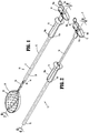
- retractor 10 the presently disclosed surgical retractor is shown generally as retractor 10 and includes an outer housing 12 defining a longitudinal axis "X", an inner shaft 14, a handle 16, an actuator grip 18, and a tool assembly 20.
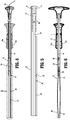
- the outer housing 12 is hollow and defines a longitudinal bore 22 ( FIG. 3 ) that receives the inner shaft 14 such that the inner shaft 14 is slidable within the longitudinal bore 22 of the outer housing 12 between a retracted position ( FIG. 2 ) and an advanced position ( FIG. 1 ).
- the handle 16 is fixedly secured to a proximal portion of the outer housing 12.
- the handle 16 is formed from half-sections 16a, 16b that are secured together about the proximal portion of the outer shaft 12 using, e.g., screws.
- the actuator grip 18 can also be formed of half-sections 18a, 18b that are secured about the proximal portion of inner shaft 14 using, e.g., screws.
- other securing techniques can be used to secure the handle 16 to the outer housing 12 and/or the actuator grip 18 to the inner shaft 14.
- the proximal portion of the inner shaft 14 may include protrusions 17 ( FIG. 3 ) that are received within slots 19 ( FIG. 3 ) defined by the grip half-sections 18a, 18b to axially secure the actuator grip 18 to the inner shaft 14.
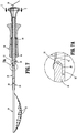
- the tool assembly 20 includes a shaft portion 24 and a tissue retractor member 26.
- the shaft portion 24 includes a proximal shaft portion and a distal shaft portion.
- the distal portion of the shaft portion 24 supports the tissue retractor member 26 and the proximal portion of the shaft portion 24 is pivotally coupled to the inner shaft 14 about a pivot pin 28 that extends in a direction substantially perpendicular to the longitudinal axis "X" of the outer housing 12.
- the tool assembly 20 can pivot between a position in which the shaft portion 24 is aligned with the longitudinal axis "X" and a position in which the shaft portion 24 forms an acute angle ⁇ ( FIG. 7B ) with the longitudinal axis "X".
- the surgical retractor 10 includes a link 30 having a distal end that is coupled to the shaft portion 24 of the tool assembly 20 at a point that is laterally offset from the pivot pin 28 such that movement of the link 30 in the direction indicated by arrow "A" in FIG. 7C causes the tool assembly 20 to pivot about the pivot pin 28 in the direction indicted by arrow "B".
- a proximal end of the link 30 extends to a position adjacent the handle 16.
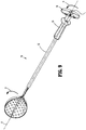
- the tool assembly 20 may be pivoted in the direction indicated by arrow "B” by actuating the link 30 to lift the intestine "I” during a procedure to mobilize the rectum/colon.
- the retractor member 26 is formed of a resilient material, e.g., spring steel, and can be furled or folded to a configuration to be received within the longitudinal bore 22 of the outer housing 12.
- the retractor member 26 has a collapsible bowl-like configuration that defines a concavity that is configured to receive and support a body organ, e.g., intestine "I" ( FIG. 10 ) during a surgical procedure.
- the retractor member 26 defines one or more openings 32 ( FIG. 3 ) that allow fluid to flow through the retractor member 26 so that fluid does not collect in the retractor member 26.
- the retractor member 26 of the tool assembly 20 includes a resilient band 34 ( FIG. 3 ) that is received within a slot 36 formed in a distal end of the shaft portion 24 of the tool assembly 20 and secured to the shaft portion 24 with a pin 38.
- the retractor member 26 can be secured to the shaft portion 24 using a variety of different fastening techniques.
- the proximal portion of the shaft portion 24 of the tool assembly 20 includes an extension 40 that is received within a clevis 42 formed on the distal portion of the inner shaft 14.
- the extension 40 is coupled to the clevis 42 by the pivot pin 28 to secure the shaft portion 24 of the tool assembly 20 to the inner shaft 14.
- the shaft portion 24 In the retracted position, the shaft portion 24 is positioned within the outer housing 12 and cannot pivot.
- a spring or biasing member 43 may be provided to urge the tool assembly 20 to a non-articulated position ( FIG. 7 ) in relation to the inner shaft 14.
- a ring seal 44 is supported within a slot 46 ( FIG. 3 ) defined between the half-sections 16a, 16b of the handle 16. The ring seal 44 is received about the inner shaft 14 and prevents fluid flow between the inner shaft 14 and the outer housing 12 through the longitudinal bore 22.
- the clevis 42 may be configured to facilitate articulation of the tool assembly 20 in only one direction.
- the distal end of the inner shaft 14 may include a stop member 50 that prevents articulation of the tool assembly 20 in a downward direction as viewed in FIG. 7 .
- the link 30 in order to articulate the tool assembly 20 about the pivot pin 28, the link 30 can be pulled in the direction indicated by arrows "A" in FIG. 7B . Since the distal portion of the link 30 is connected to the proximal portion of the shaft portion 24 of the tool assembly 20 at a position offset from the pivot pin 28, movement of the link 30 in the direction "A” will pivot the tool assembly 20 about the axis defined the pivot pin 28 in the direction indicated by arrow "B" in FIG. 7B .
- a proximal end of the link 30 may include a hand grip to facilitate grasping of the link 30 by the clinician.
- the inner shaft 14 can be rotated within the outer housing 12 about the longitudinal axis "X" in the direction indicated by arrows "D". This can be accomplished by holding the handle 16 stationary and rotating the actuator grip 18 in the direction indicated by arrow "D" or in the opposite direction.
- the outer housing 12 of the surgical retractor 10 is inserted through a cannula 80 that extends through an incision "I" in the abdominal wall 82 to access the abdominal cavity 84.
- the inner shaft 14 is in a retracted position with the tool assembly 20 confined within the longitudinal bore 22 ( FIG. 6 ) of the outer housing 12.
- the inner shaft 14 can be moved to the advanced position within the outer housing 12 to move the surgical retractor 10 to the deployed state with the tool assembly 20 extending from the outer housing 12.
- the retractor member 26 of the tool assembly 20 can be manipulated to lift the intestine "I” upwardly to move the intestines "I” off of the rectum/colon to provide access to the rectum/colon.
- the link 30 in order to further lift the intestine "I" off of the rectum/colon, the link 30 can be pulled proximally ( FIG. 7A ) to pivot the tool assembly 20 about the pivot member 28.
- the inner shaft 12 can be retracted by pulling the actuator grip 18 proximally while holding the handle 16 stationary to move the tool assembly 20 back to the non-deployed state positioned within the outer tube 12.
- FIGS. 11-15 illustrate another exemplary embodiment of the presently disclosed surgical retractor shown generally as retractor 100.
- the surgical retractor 100 includes an outer housing 112 defining a longitudinal axis "Y", an inner shaft 114, a handle 116, an actuator grip 118, and a tool assembly 120.
- the tool assembly 120 includes a shaft portion 124 and a retractor member 126.
- the outer housing 112 is hollow and defines a longitudinal bore 122 ( FIG. 15 ).
- the longitudinal bore 122 is dimensioned to receive the inner shaft 114 such that the inner shaft 114 is slidable within the longitudinal bore 122 between a retracted position ( FIG. 12 ) and an advanced position ( FIG. 11 ).
- the handle 116 is fixedly secured to a proximal portion of the outer housing 112.
- the distal portion of the inner shaft 114 supports the tool assembly 120.
- the surgical retractor 100 is substantially as described above with regard to the surgical retractor 10 except that the configuration of the retractor member 126 is changed. As such, only the retractor member 126 of the surgical retractor 100 will be described in further detail herein.
- the shaft portion 124 is pivotably coupled to the retractor member 126 by a pivot pin 128 in substantially the same manner that the shaft portion 24 is pivotably coupled to the retractor member 26.
- the retractor member 126 includes a base portion 130 and a series of tines 132 that extend distally from the base portion 132.
- the base portion 132 and the tines 130 are curved along their longitudinal axis "Y" such that the retractor member 126 defines a slight concavity140.
- the surgical retractor 100 operates in substantially the same manner as the surgical retractor 10. Accordingly, no further description of the is provided herein.
Applications Claiming Priority (2)
| Application Number | Priority Date | Filing Date | Title |
|---|---|---|---|
| US201862687827P | 2018-06-21 | 2018-06-21 | |
| US16/364,779 US20190388080A1 (en) | 2018-06-21 | 2019-03-26 | Surgical retractors |
Publications (2)
| Publication Number | Publication Date |
|---|---|
| EP3586764A2 true EP3586764A2 (de) | 2020-01-01 |
| EP3586764A3 EP3586764A3 (de) | 2020-03-18 |
Family
ID=66999755
Family Applications (1)
| Application Number | Title | Priority Date | Filing Date |
|---|---|---|---|
| EP19181512.5A Withdrawn EP3586764A3 (de) | 2018-06-21 | 2019-06-20 | Chirurgische retraktoren |
Country Status (3)
| Country | Link |
|---|---|
| US (1) | US20190388080A1 (de) |
| EP (1) | EP3586764A3 (de) |
| CN (1) | CN110623694A (de) |
Family Cites Families (5)
| Publication number | Priority date | Publication date | Assignee | Title |
|---|---|---|---|---|
| US4126555A (en) * | 1977-10-31 | 1978-11-21 | Adams Richard M | Tea strainer with hinged handle |
| US5308327A (en) * | 1991-11-25 | 1994-05-03 | Advanced Surgical Inc. | Self-deployed inflatable retractor |
| US6969349B1 (en) * | 1997-09-17 | 2005-11-29 | Origin Medsystem, Inc. | Device to permit offpump beating heart coronary bypass surgery |
| WO2012094364A2 (en) * | 2011-01-04 | 2012-07-12 | The Johns Hopkins University | Minimally invasive laparoscopic retractor |
| DE102013103905A1 (de) * | 2013-04-18 | 2014-10-23 | Karl Storz Gmbh & Co. Kg | Medizinisches Instrument |
-
2019
- 2019-03-26 US US16/364,779 patent/US20190388080A1/en not_active Abandoned
- 2019-06-17 CN CN201910521801.5A patent/CN110623694A/zh active Pending
- 2019-06-20 EP EP19181512.5A patent/EP3586764A3/de not_active Withdrawn
Also Published As
| Publication number | Publication date |
|---|---|
| US20190388080A1 (en) | 2019-12-26 |
| CN110623694A (zh) | 2019-12-31 |
| EP3586764A3 (de) | 2020-03-18 |
Similar Documents
| Publication | Publication Date | Title |
|---|---|---|
| US5474057A (en) | Laparoscopic dissection tension retractor device and method | |
| US5656012A (en) | Surgical retractor | |
| JP6356667B2 (ja) | 最小侵襲胃腸手術処置のためのマルチルーメンカテーテル・リトラクタシステム | |
| US11369401B2 (en) | Reverse seam ripper dissector | |
| KR101822685B1 (ko) | 좌우로 이격된 가상 삽입 지점을 갖는 단일 포트 복강경의 접근을 위한 기구 | |
| US8092489B2 (en) | Tissue grasping apparatus | |
| EP3560429B1 (de) | Probenentnahmevorrichtung | |
| JP2013085957A (ja) | 胸郭手順のための外科手術用回収装置 | |
| JP2005524475A (ja) | 内視鏡検査器官開創器およびこれを使用する方法 | |
| EP1857053A2 (de) | Lumenstabilisator für die endoskopische Mukosaresektion | |
| US10478208B2 (en) | Endoscopic submucosal dissection hood | |
| EP3498199B1 (de) | Laparoskopische gewebebehandlungsvorrichtung | |
| US8900135B2 (en) | Single incision deployable platform | |
| WO2013132861A1 (ja) | 領域確保用器具および領域確保用器具を備えた内視鏡 | |
| US20050203345A1 (en) | Articulating paddle elevator and arthroscopic method for using same | |
| EP3586764A2 (de) | Chirurgische retraktoren | |
| US20220160347A1 (en) | Endoscopic stitching device for supporting suture needles in various orientations | |
| EP3730064A1 (de) | Vorrichtung zum verschliessen von einschnitten an portstellen | |
| US20050101839A1 (en) | Thorax mounted stabilization platform |
Legal Events
| Date | Code | Title | Description |
|---|---|---|---|
| PUAI | Public reference made under article 153(3) epc to a published international application that has entered the european phase |
Free format text: ORIGINAL CODE: 0009012 |
|
| STAA | Information on the status of an ep patent application or granted ep patent |
Free format text: STATUS: THE APPLICATION HAS BEEN PUBLISHED |
|
| AK | Designated contracting states |
Kind code of ref document: A2 Designated state(s): AL AT BE BG CH CY CZ DE DK EE ES FI FR GB GR HR HU IE IS IT LI LT LU LV MC MK MT NL NO PL PT RO RS SE SI SK SM TR |
|
| AX | Request for extension of the european patent |
Extension state: BA ME |
|
| PUAL | Search report despatched |
Free format text: ORIGINAL CODE: 0009013 |
|
| AK | Designated contracting states |
Kind code of ref document: A3 Designated state(s): AL AT BE BG CH CY CZ DE DK EE ES FI FR GB GR HR HU IE IS IT LI LT LU LV MC MK MT NL NO PL PT RO RS SE SI SK SM TR |
|
| AX | Request for extension of the european patent |
Extension state: BA ME |
|
| RIC1 | Information provided on ipc code assigned before grant |
Ipc: A61B 17/02 20060101AFI20200211BHEP |
|
| STAA | Information on the status of an ep patent application or granted ep patent |
Free format text: STATUS: REQUEST FOR EXAMINATION WAS MADE |
|
| 17P | Request for examination filed |
Effective date: 20200915 |
|
| RBV | Designated contracting states (corrected) |
Designated state(s): AL AT BE BG CH CY CZ DE DK EE ES FI FR GB GR HR HU IE IS IT LI LT LU LV MC MK MT NL NO PL PT RO RS SE SI SK SM TR |
|
| GRAP | Despatch of communication of intention to grant a patent |
Free format text: ORIGINAL CODE: EPIDOSNIGR1 |
|
| STAA | Information on the status of an ep patent application or granted ep patent |
Free format text: STATUS: GRANT OF PATENT IS INTENDED |
|
| INTG | Intention to grant announced |
Effective date: 20210514 |
|
| STAA | Information on the status of an ep patent application or granted ep patent |
Free format text: STATUS: THE APPLICATION IS DEEMED TO BE WITHDRAWN |
|
| 18D | Application deemed to be withdrawn |
Effective date: 20210925 |