EP3586751A1 - Dispositif de fluoroscopie à rayons x et procédé de tomographie à rayons x - Google Patents
Dispositif de fluoroscopie à rayons x et procédé de tomographie à rayons x Download PDFInfo
- Publication number
- EP3586751A1 EP3586751A1 EP18757460.3A EP18757460A EP3586751A1 EP 3586751 A1 EP3586751 A1 EP 3586751A1 EP 18757460 A EP18757460 A EP 18757460A EP 3586751 A1 EP3586751 A1 EP 3586751A1
- Authority
- EP
- European Patent Office
- Prior art keywords
- ray
- interest
- tomographic layer
- tomographic
- imaging
- Prior art date
- Legal status (The legal status is an assumption and is not a legal conclusion. Google has not performed a legal analysis and makes no representation as to the accuracy of the status listed.)
- Granted
Links
- 238000000034 method Methods 0.000 title claims abstract description 40
- 238000003325 tomography Methods 0.000 title claims description 46
- 238000003384 imaging method Methods 0.000 claims abstract description 298
- 238000013459 approach Methods 0.000 claims abstract description 42
- 230000003247 decreasing effect Effects 0.000 claims description 36
- 210000002455 dental arch Anatomy 0.000 claims description 30
- 238000012545 processing Methods 0.000 claims description 21
- 230000008859 change Effects 0.000 claims description 3
- 102100032919 Chromobox protein homolog 1 Human genes 0.000 abstract description 23
- 101000797584 Homo sapiens Chromobox protein homolog 1 Proteins 0.000 abstract description 23
- 230000002452 interceptive effect Effects 0.000 abstract description 2
- 238000013170 computed tomography imaging Methods 0.000 description 36
- 102100025535 Delta(14)-sterol reductase TM7SF2 Human genes 0.000 description 34
- 101000924552 Homo sapiens Angiopoietin-1 Proteins 0.000 description 34
- 101001056901 Homo sapiens Delta(14)-sterol reductase TM7SF2 Proteins 0.000 description 34
- 238000001514 detection method Methods 0.000 description 21
- 101100191129 Arabidopsis thaliana LOI1 gene Proteins 0.000 description 18
- 230000004048 modification Effects 0.000 description 16
- 238000012986 modification Methods 0.000 description 16
- 210000001847 jaw Anatomy 0.000 description 15
- 230000001105 regulatory effect Effects 0.000 description 12
- 230000007423 decrease Effects 0.000 description 11
- 230000006870 function Effects 0.000 description 10
- 230000001276 controlling effect Effects 0.000 description 9
- 238000010586 diagram Methods 0.000 description 9
- 238000003860 storage Methods 0.000 description 6
- 230000001965 increasing effect Effects 0.000 description 5
- 101150033538 Rala gene Proteins 0.000 description 4
- 238000010521 absorption reaction Methods 0.000 description 4
- 230000007246 mechanism Effects 0.000 description 4
- 230000005540 biological transmission Effects 0.000 description 3
- 238000003745 diagnosis Methods 0.000 description 3
- 230000010354 integration Effects 0.000 description 3
- 238000000926 separation method Methods 0.000 description 3
- 230000004304 visual acuity Effects 0.000 description 3
- 230000001174 ascending effect Effects 0.000 description 2
- 238000002591 computed tomography Methods 0.000 description 2
- 239000000470 constituent Substances 0.000 description 2
- 239000004973 liquid crystal related substance Substances 0.000 description 2
- 230000002093 peripheral effect Effects 0.000 description 2
- 230000007480 spreading Effects 0.000 description 2
- 238000003892 spreading Methods 0.000 description 2
- 210000001738 temporomandibular joint Anatomy 0.000 description 2
- 101100162222 Schizosaccharomyces pombe (strain 972 / ATCC 24843) agn1 gene Proteins 0.000 description 1
- 230000008901 benefit Effects 0.000 description 1
- 238000010276 construction Methods 0.000 description 1
- 238000012937 correction Methods 0.000 description 1
- 238000005520 cutting process Methods 0.000 description 1
- 238000013461 design Methods 0.000 description 1
- 230000000694 effects Effects 0.000 description 1
- 230000003028 elevating effect Effects 0.000 description 1
- 230000004907 flux Effects 0.000 description 1
- 230000001678 irradiating effect Effects 0.000 description 1
- 230000008569 process Effects 0.000 description 1
- 230000004044 response Effects 0.000 description 1
- 238000004904 shortening Methods 0.000 description 1
- 239000013598 vector Substances 0.000 description 1
- 230000000007 visual effect Effects 0.000 description 1
Images


Classifications
-
- A—HUMAN NECESSITIES
- A61—MEDICAL OR VETERINARY SCIENCE; HYGIENE
- A61B—DIAGNOSIS; SURGERY; IDENTIFICATION
- A61B6/00—Apparatus or devices for radiation diagnosis; Apparatus or devices for radiation diagnosis combined with radiation therapy equipment
- A61B6/58—Testing, adjusting or calibrating thereof
- A61B6/588—Setting distance between source unit and detector unit
-
- A—HUMAN NECESSITIES
- A61—MEDICAL OR VETERINARY SCIENCE; HYGIENE
- A61B—DIAGNOSIS; SURGERY; IDENTIFICATION
- A61B6/00—Apparatus or devices for radiation diagnosis; Apparatus or devices for radiation diagnosis combined with radiation therapy equipment
- A61B6/02—Arrangements for diagnosis sequentially in different planes; Stereoscopic radiation diagnosis
- A61B6/027—Arrangements for diagnosis sequentially in different planes; Stereoscopic radiation diagnosis characterised by the use of a particular data acquisition trajectory, e.g. helical or spiral
-
- A—HUMAN NECESSITIES
- A61—MEDICAL OR VETERINARY SCIENCE; HYGIENE
- A61B—DIAGNOSIS; SURGERY; IDENTIFICATION
- A61B6/00—Apparatus or devices for radiation diagnosis; Apparatus or devices for radiation diagnosis combined with radiation therapy equipment
- A61B6/02—Arrangements for diagnosis sequentially in different planes; Stereoscopic radiation diagnosis
- A61B6/025—Tomosynthesis
-
- A—HUMAN NECESSITIES
- A61—MEDICAL OR VETERINARY SCIENCE; HYGIENE
- A61B—DIAGNOSIS; SURGERY; IDENTIFICATION
- A61B6/00—Apparatus or devices for radiation diagnosis; Apparatus or devices for radiation diagnosis combined with radiation therapy equipment
- A61B6/02—Arrangements for diagnosis sequentially in different planes; Stereoscopic radiation diagnosis
- A61B6/03—Computed tomography [CT]
- A61B6/032—Transmission computed tomography [CT]
- A61B6/035—Mechanical aspects of CT
-
- A—HUMAN NECESSITIES
- A61—MEDICAL OR VETERINARY SCIENCE; HYGIENE
- A61B—DIAGNOSIS; SURGERY; IDENTIFICATION
- A61B6/00—Apparatus or devices for radiation diagnosis; Apparatus or devices for radiation diagnosis combined with radiation therapy equipment
- A61B6/44—Constructional features of apparatus for radiation diagnosis
- A61B6/4429—Constructional features of apparatus for radiation diagnosis related to the mounting of source units and detector units
- A61B6/4435—Constructional features of apparatus for radiation diagnosis related to the mounting of source units and detector units the source unit and the detector unit being coupled by a rigid structure
- A61B6/4441—Constructional features of apparatus for radiation diagnosis related to the mounting of source units and detector units the source unit and the detector unit being coupled by a rigid structure the rigid structure being a C-arm or U-arm
-
- A—HUMAN NECESSITIES
- A61—MEDICAL OR VETERINARY SCIENCE; HYGIENE
- A61B—DIAGNOSIS; SURGERY; IDENTIFICATION
- A61B6/00—Apparatus or devices for radiation diagnosis; Apparatus or devices for radiation diagnosis combined with radiation therapy equipment
- A61B6/44—Constructional features of apparatus for radiation diagnosis
- A61B6/4429—Constructional features of apparatus for radiation diagnosis related to the mounting of source units and detector units
- A61B6/4452—Constructional features of apparatus for radiation diagnosis related to the mounting of source units and detector units the source unit and the detector unit being able to move relative to each other
-
- A—HUMAN NECESSITIES
- A61—MEDICAL OR VETERINARY SCIENCE; HYGIENE
- A61B—DIAGNOSIS; SURGERY; IDENTIFICATION
- A61B6/00—Apparatus or devices for radiation diagnosis; Apparatus or devices for radiation diagnosis combined with radiation therapy equipment
- A61B6/44—Constructional features of apparatus for radiation diagnosis
- A61B6/4476—Constructional features of apparatus for radiation diagnosis related to motor-assisted motion of the source unit
-
- A—HUMAN NECESSITIES
- A61—MEDICAL OR VETERINARY SCIENCE; HYGIENE
- A61B—DIAGNOSIS; SURGERY; IDENTIFICATION
- A61B6/00—Apparatus or devices for radiation diagnosis; Apparatus or devices for radiation diagnosis combined with radiation therapy equipment
- A61B6/46—Arrangements for interfacing with the operator or the patient
- A61B6/467—Arrangements for interfacing with the operator or the patient characterised by special input means
- A61B6/469—Arrangements for interfacing with the operator or the patient characterised by special input means for selecting a region of interest [ROI]
-
- A—HUMAN NECESSITIES
- A61—MEDICAL OR VETERINARY SCIENCE; HYGIENE
- A61B—DIAGNOSIS; SURGERY; IDENTIFICATION
- A61B6/00—Apparatus or devices for radiation diagnosis; Apparatus or devices for radiation diagnosis combined with radiation therapy equipment
- A61B6/50—Apparatus or devices for radiation diagnosis; Apparatus or devices for radiation diagnosis combined with radiation therapy equipment specially adapted for specific body parts; specially adapted for specific clinical applications
- A61B6/501—Apparatus or devices for radiation diagnosis; Apparatus or devices for radiation diagnosis combined with radiation therapy equipment specially adapted for specific body parts; specially adapted for specific clinical applications for diagnosis of the head, e.g. neuroimaging or craniography
-
- A—HUMAN NECESSITIES
- A61—MEDICAL OR VETERINARY SCIENCE; HYGIENE
- A61B—DIAGNOSIS; SURGERY; IDENTIFICATION
- A61B6/00—Apparatus or devices for radiation diagnosis; Apparatus or devices for radiation diagnosis combined with radiation therapy equipment
- A61B6/50—Apparatus or devices for radiation diagnosis; Apparatus or devices for radiation diagnosis combined with radiation therapy equipment specially adapted for specific body parts; specially adapted for specific clinical applications
- A61B6/51—Apparatus or devices for radiation diagnosis; Apparatus or devices for radiation diagnosis combined with radiation therapy equipment specially adapted for specific body parts; specially adapted for specific clinical applications for dentistry
-
- A—HUMAN NECESSITIES
- A61—MEDICAL OR VETERINARY SCIENCE; HYGIENE
- A61B—DIAGNOSIS; SURGERY; IDENTIFICATION
- A61B6/00—Apparatus or devices for radiation diagnosis; Apparatus or devices for radiation diagnosis combined with radiation therapy equipment
- A61B6/52—Devices using data or image processing specially adapted for radiation diagnosis
- A61B6/5205—Devices using data or image processing specially adapted for radiation diagnosis involving processing of raw data to produce diagnostic data
-
- A—HUMAN NECESSITIES
- A61—MEDICAL OR VETERINARY SCIENCE; HYGIENE
- A61B—DIAGNOSIS; SURGERY; IDENTIFICATION
- A61B6/00—Apparatus or devices for radiation diagnosis; Apparatus or devices for radiation diagnosis combined with radiation therapy equipment
- A61B6/54—Control of apparatus or devices for radiation diagnosis
- A61B6/545—Control of apparatus or devices for radiation diagnosis involving automatic set-up of acquisition parameters
-
- A—HUMAN NECESSITIES
- A61—MEDICAL OR VETERINARY SCIENCE; HYGIENE
- A61B—DIAGNOSIS; SURGERY; IDENTIFICATION
- A61B6/00—Apparatus or devices for radiation diagnosis; Apparatus or devices for radiation diagnosis combined with radiation therapy equipment
- A61B6/54—Control of apparatus or devices for radiation diagnosis
- A61B6/547—Control of apparatus or devices for radiation diagnosis involving tracking of position of the device or parts of the device
-
- A—HUMAN NECESSITIES
- A61—MEDICAL OR VETERINARY SCIENCE; HYGIENE
- A61B—DIAGNOSIS; SURGERY; IDENTIFICATION
- A61B6/00—Apparatus or devices for radiation diagnosis; Apparatus or devices for radiation diagnosis combined with radiation therapy equipment
- A61B6/58—Testing, adjusting or calibrating thereof
- A61B6/589—Setting distance between source unit and patient
Definitions
- the present invention relates to a technique of performing X-ray tomography to acquire a tomographic image of a tomographic layer of interest.
- An X-ray CT (computed tomography) imaging apparatus that performs tomographic imaging on any site of a human body is widely known in the field of medical X-ray diagnosis.
- image information an X-ray projection image or a transmission image
- Image processing is performed on the obtained image information to generate a tomographic image indicating a tomographic plane obtained by cutting any site such as a head and a body.
- Patent Document 1 discloses a technique of performing CT imaging by reducing an influence of a high X-ray absorption site existing in the subject using a control model based on high X-ray absorption site information existing in the subject. Specifically, at least one of an increase in X-ray output and a decrease in turning speed is performed at timing at which an X-ray cone beam reaches the high X-ray absorption site (for example, a cervical spine). In Patent Document 1, a clear tomographic image is obtained by reducing the influence of the high X-ray absorption site.
- Patent Document 1 Japanese Patent Application Laid-Open No. 2010-075682
- Patent Document 1 there is a possibility that an exposure dose of the subject is increased more than usual by increasing the X-ray output or decreasing the turning speed. Because the increase in the exposure dose is not desirable, there is a demand for an alternative technique of acquiring a clear tomographic image.
- resolution of the X-ray projection image depends on resolving power of the X-ray detector and a size of a focal plane of the X-ray. From the viewpoint of the resolving power of the X-ray detector, a magnification factor of the X-ray projection image is desirably enlarged as much as possible.
- blurring occurs in the X-ray projection image due to the fact that the focal plane of the X-ray has a certain size. The blurring caused by the focal plane also increases with increasing magnification factor of the X-ray projection image. For this reason, for a general X-ray detector, a clear (that is, high-resolution) X-ray projection image can be acquired by decreasing the magnification factor as much as possible (by bringing the magnification factor close to 1).
- the present invention has been made in view of the above problems, and an object of the present invention is to provide a technique of acquiring a high-resolution X-ray projection image without affecting the turning of the X-ray generator and the X-ray detector.
- an X-ray tomography apparatus includes: an X-ray generator that emits an X-ray beam; an X-ray detector that detects the X-ray beam emitted from the X-ray generator; a support that supports the X-ray generator and the X-ray detector; a tomographic layer-of-interest setting unit that sets a tomographic layer of interest; a turning drive unit that turns the X-ray generator and the X-ray detector relative to the tomographic layer of interest about a turning center axis set between the X-ray generator and the X-ray detector; a movement drive unit that moves at least one of the X-ray generator and the X-ray detector relative to the tomographic layer of interest in a direction perpendicular to the turning center axis; an image processor that generates an X-ray tomographic image indicating the tomographic layer of interest by performing image processing on a plurality of X-ray projection images generated based
- the controller causes the X-ray detector to relatively approach the tomographic layer of interest and/or to relatively move the X-ray generator away from the tomographic layer of interest as compared to when the center axis X-ray is not orthogonal to the tomographic layer of interest.
- a second aspect is the X-ray tomography apparatus of the first aspect, in which the support includes a turning arm that supports the X-ray generator at one end side while supporting the X-ray detector at the other end side, and the turning drive unit turns the turning arm via a shaft, the shaft being connected to a position between the X-ray generator and the X-ray detector in the turning arm.
- a third aspect is the X-ray tomography apparatus of the second aspect, in which the movement drive unit moves the shaft of the turning arm in the direction perpendicular to the turning center axis.
- a fourth aspect is the X-ray tomography apparatus of any one of the first to third aspects, in which the controller starts at least one of the approach of the X-ray detector to the tomographic layer of interest and the movement of the X-ray generator away from the tomographic layer of interest before the center axis X-ray becomes orthogonal to the tomographic layer of interest, and the controller starts at least one of the movement of the X-ray detector away from the tomographic layer of interest and the approach of the X-ray generator to the tomographic layer of interest after the center axis X-ray becomes orthogonal to the tomographic layer of interest.
- a fifth aspect is the X-ray tomography apparatus of any one of the first to fourth aspects, which further includes an imaging region designation receiving unit that receives designation of an imaging region in which a plurality of X-ray projection images are acquired by irradiation of the X-ray beam from a plurality of directions.
- a sixth aspect is the X-ray tomography apparatus of the fifth aspect, in which the tomographic layer-of-interest setting unit sets the tomographic layer of interest according to the imaging region received by the imaging region designation receiving unit.
- a seventh aspect is the X-ray tomography apparatus of the sixth aspect, in which the imaging region designation receiving unit receives designation of the imaging region so as to include a part of a dental arch, and the tomographic layer-of-interest setting unit sets a tomographic layer along said part of the dental arch included in the imaging region as the tomographic layer of interest.
- An eighth aspect is the X-ray tomography apparatus of any one of the first aspect to the seventh aspect, in which the image processor performs image processing after matching magnification factors of the plurality of X-ray projection images with each other, and generates the X-ray tomographic image.
- a ninth aspect is the X-ray tomography apparatus of any one of the first aspect to the eighth aspect, which further includes a tomographic thickness designation receiving unit that receives designation of a tomographic thickness of the tomographic layer of interest.
- the controller determines an incident angle when the X-ray detector is caused to approach the tomographic layer of interest according to the designated tomographic thickness.
- an X-ray tomography method includes: (a) a step of setting a tomographic layer of interest; (b) a step of turning an X-ray generator and an X-ray detector relative to the tomographic layer of interest around a turning center axis set between the X-ray generator and the X-ray detector while the tomographic layer of interest is disposed between the X-ray generator and the X-ray detector; (c) a step of detecting an X-ray beam emitted from the X-ray generator using the X-ray detector in the step (b); (d) a step of causing, when a center axis X-ray passing through the turning center axis in the X-ray beam is orthogonal to the tomographic layer of interest in the step (b), the X-ray detector to relatively approach the tomographic layer of interest and/or to relatively move the X-ray generator away from the tomographic layer of interest as compared to when the
- an X-ray tomography apparatus includes: an X-ray generator that emits an X-ray beam; an X-ray detector that detects the X-ray beam emitted from the X-ray generator; a support that supports the X-ray generator and the X-ray detector; a tomographic layer-of-interest setting unit that sets a tomographic layer of interest; a turning drive unit that turns the X-ray generator and the X-ray detector relative to the tomographic layer of interest about a turning center axis set between the X-ray generator and the X-ray detector; a movement drive unit that moves at least one of the X-ray generator and the X-ray detector relative to the tomographic layer of interest in a direction perpendicular to the turning center axis; an image processor that generates an X-ray tomographic image indicating the tomographic layer of interest by performing image processing on a plurality of X-ray projection images generated based on an output signal
- the controller controls movement of at least one of the X-ray generator and the X-ray detector such that a magnification factor is relatively decreased in a state in which a irradiation axis of the X-ray beam is incident on the tomographic layer of interest in a confronting manner when the state in which the irradiation axis of the X-ray beam is incident on the tomographic layer of interest in the confronting manner and a state in which the irradiation axis of the X-ray beam is incident on the tomographic layer of interest in a non-confronting manner are compared to each other, while the X-ray generator and the X-ray detector are turned.
- the X-ray detector when the center axis X-ray of the X-ray beam is orthogonal to the tomographic layer of interest, the X-ray detector is caused to approach the tomographic layer of interest or the X-ray detector is moved away from the tomographic layer of interest as compared to when the center axis X-ray is not orthogonal to the tomographic layer of interest, which allows the magnification factor of the X-ray projection image to be decreased in the X-ray detector.
- the X-ray detector is caused to approach the tomographic layer of interest by limiting the X-ray generator and the X-ray detector to a part of the turning angle during turning of the X-ray generator and the X-ray detector relative to the subject, which prevents the X-ray detector from contacting with the subject.
- the X-ray generator can be prevented from colliding with another member by moving the X-ray generator away from the tomographic layer of interest.
- the turning arm is turned via the shaft, which allows the X-ray generator and the X-ray detector to be integrally turned.
- the X-ray detector by moving the shaft, the X-ray detector can be moved together with the X-ray generator in a direction in which the X-ray detector is caused to approach to and moved away from the tomographic layer of interest. Consequently, the magnification factor of the projection image projected onto the X-ray detector can be changed.
- the magnification factor can be decreased before the center axis X-ray becomes orthogonal to the tomographic layer of interest, namely, until the X-ray generator becomes the confronting state.
- the X-ray detector is moved away from the tomographic layer of interest or the X-ray generator is caused to approach the tomographic layer of interest, which prevents the X-ray detector from contacting with the subject, or which prevents the X-ray generator from colliding with a peripheral member.
- an operator can designate an imaging region irradiated with the X-rays in the subject.
- the tomographic layer of interest is automatically set according to the set imaging region, so that the operator can eliminate the operation to set the tomographic layer of interest.
- the tomographic layer of interest is set along the dental arch. Consequently, the tomographic image of the tomographic layer of interest suitable for a dental diagnosis can be acquired.
- the dental arch is unevenly distributed in front of the head, and extends along a front edge of the head. For this reason, when the X-ray generator confronts the tomographic layer of interest set along the dental arch, the X-ray detector can be caused to approach the tomographic layer of interest without touching with the head. Thus, the high-resolution X-ray tomographic image can easily be obtained for the tomographic layer of interest in a part of the dental arch.
- the X-ray tomography apparatus of the eighth aspect by previously matching the magnification factors of the plurality of X-ray projection images with each other, positions onto which each point in the imaging region is projected can be matched with each other in the plurality of X-ray projection images. Consequently, parallelization of arithmetic processing is promoted, so that time necessary for the arithmetic processing can be shortened when an arithmetic processing apparatus such as a GPU excellent in parallel processing is used.
- the suitable incident angle is determined according to the designated tomographic thickness when the magnification factor is changed. Consequently, the X-ray tomographic image indicating the tomographic layer of interest having the designated tomographic thickness can suitably be acquired.
- the X-ray detector when the center axis X-ray of the X-ray beam is orthogonal to the tomographic layer of interest, the X-ray detector is caused to approach the tomographic layer of interest or the X-ray generator is moved away from the tomographic layer of interest as compared to when the center axis X-ray is not orthogonal to the tomographic layer of interest. Consequently, the magnification factor of the X-ray projection image projected onto the X-ray detector can be decreased.
- the X-ray detector is caused to approach the tomographic layer of interest by limiting the X-ray generator and the X-ray detector to a part of the turning angle during turning of the X-ray generator and the X-ray detector relative to the subject, which prevents the X-ray detector from contacting with the subject.
- the X-ray generator can be prevented from colliding with another member by moving the X-ray generator away from the tomographic layer of interest.
- movement of at least one of the X-ray generator and the X-ray detector is controlled while the irradiation axis of the X-ray beam is incident on the tomographic layer of interest in the confronting manner, which allows the magnification factor of the X-ray projection image to be decreased in the X-ray detector when the state in which the irradiation axis of the X-ray beam is incident on the tomographic layer of interest in the confronting manner is compared with the state in which the irradiation axis is incident on the tomographic layer of interest in the non-confronting manner.
- the blurring caused by the influence of the focal size of the X-ray is reduced on the X-ray projection image that is obtained when the irradiation axis of the X-ray beam is incident on the tomographic layer of interest in the confronting manner, so that the resolution of the X-ray projection image can be improved.
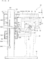
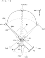
- Fig. 1 is a view illustrating a configuration of an X-ray tomography apparatus 10 according to an embodiment.
- Fig. 2 is a side view schematically illustrating an imaging unit 20 of the embodiment.
- Fig. 3 is a view conceptually illustrating a tomographic layer of interest LOI of the embodiment.
- a right-handed XYZ (X-axis, Y-axis, Z-axis) orthogonal coordinate system and a right-handed xyz (x-axis, y-axis, z-axis) orthogonal coordinate system are defined in Fig. 1 . Because a supporting relationship of a post 70 and a support 60 will be described in detail later, the detailed description is not made here, but the supporting relationship will be described in the minimum necessary range for explanation of each axial direction of a coordinate.
- the post 70 is erected on a base 7B placed on a ground on which the imaging unit 20 is installed, and an upper frame 64 includes a base end at a portion contacting with the post 70, and extends in one direction crossing a longitudinal direction of the post 70 from the base end.
- the upper frame 64 pivotally supports a turning unit 67 via a shaft 66.
- a turning axis 66A about which a turning arm 62 turns mechanically passes through the shaft 66.
- the axial direction of the turning axis 66A is a Z-axis direction.
- the X-ray tomography apparatus 10 in Fig. 1 is a standing type imaging apparatus.
- the Z-axis direction is a vertical direction, and is made to coincide with a body axis direction of a subject M1 positioned in the imaging unit 20.
- An arm 726 of a subject holder 72 has a base end in a portion contacting with the post 70, and extends in the same direction as the upper frame 64 from the base end.
- a head MH of the subject M1 is supported by a head support 72H such as a chin rest 722 provided on a leading end side of the arm 726.
- the post 70 extends in the Z-axis direction with respect to the base 7B.
- the base 7B spreads on the ground, and extends to at least a foot of the subject M1.
- each direction is defined on the assumption that the head MH is positioned and supported at a defined regular location by the head support 72H while facing in a regular direction.
- a front-rear direction of the head MH is a Y-axis direction
- a left-right direction of the head MH is an X-axis direction.
- the Z-axis direction is referred to as a Z-direction
- a Y-axis direction is referred to as a Y-direction
- an X-axis direction is referred to as an X-direction.
- a front of the head MH namely, the surface of the imaging unit 20 viewed from the direction in which the face is viewed from the front is set to the front of the imaging unit 20.
- Fig. 2 is a front view of the imaging unit 20.
- the upper frame 64 and the arm 726 extend in the X-direction (the -X-direction described below) from the post 70.
- the upper frame 64 and the arm 726 do not necessarily extend only in the X-direction.
- the upper frame 64 and the arm 726 may once extend in the Y-direction (the -Y-direction described below) and extend in the X-direction on the way.
- a + side and a - side in each axial direction will be described below.
- the direction from the head MH toward the base 7B, namely, a lower side is set to a -Z-side
- the direction away from the base 7B namely, an upper side is set to a +Z-side.
- the side supported by the upper frame 64 is the +Z-side
- the side supporting the turning arm 62 is the -Z-side.
- the direction in front of the head MH is set to a +Y-side
- the direction at the back of the head MH is set to a -Y-side.
- a right direction of the head MH is set to a +X-side
- a left direction is set to a -X-side.
- Each axial direction, each +, and each - are illustrated in a head perspective view MHPI that is a perspective view of the head MH in Fig. 1 .
- a visual line direction is defined as follows. In each axial direction, the direction viewed in ascending order of a numerical value is viewed as a + direction view, and the direction viewed in descending order of the numerical value is set to a - direction view.
- +ZV illustrated in the head perspective view MHPI is a +Z-direction view
- -ZV is a -Z-direction view
- +YV is a +Y-direction view
- -YV is a -Y-direction view
- +XV is a +X-direction view
- -XV is a -X-direction view.
- An xyz-orthogonal coordinate system is an orthogonal coordinate system defined in the turning arm 62 that rotates with respect to a portion (for example, the post 70) fixed in the imaging unit 20.
- the axial direction of the shaft 66 is set to a z-axis direction, and the z-axis direction is matched with the Z-axis direction of an XYZ-orthogonal coordinate system.
- a direction in which the X-ray generator 42 and the X-ray detector 52 are opposed to each other is set to a y-axis direction, and a direction orthogonal to the y-axis direction and the z-axis direction is set to an x-axis direction.
- the z-axis direction is referred to as a z-direction
- the y-axis direction is referred to as a y-direction
- the x-axis direction is referred to as an x-direction.
- the side of the X-ray detector 52 as viewed from the X-ray generator 42 is set to a +y-side.
- the right side toward the +y-side is set to a +x-side.
- the upper side in the vertical direction in the z-axis direction is set to a +z-side.
- the direction viewed in ascending order of the numerical value is referred to as the + direction view, and the direction viewed in descending order of the numerical value is referred to as the - direction view.
- the X-ray tomography apparatus 10 includes the imaging unit 20 and an information processor 30.
- the imaging unit 20 is an apparatus that collects X-ray projection data by performing X-ray imaging of the subject M1.
- the imaging unit 20 includes an X-ray generation unit 40, an X-ray detection unit 50, the support 60, the post 70, and an imaging controller 80.
- the X-ray generation unit 40 includes the X-ray generator 42 and an X-ray regulating unit 44.
- the X-ray generator 42 includes an X-ray tube that is an X-ray source that emits an X-ray. Intensity (output intensity) of an X-ray beam emitted from the X-ray generator 42 can be controlled by changing voltage and/or current supplied to the X-ray tube. Operation of the X-ray generator 42 is controlled by an X-ray generation controller 810 of the imaging controller 80.
- the X-ray regulating unit 44 regulates spread of the X-ray beam emitted from the X-ray generator 42, and forms the X-ray beam having a shape according to an imaging purpose. That is, the X-ray regulating unit 44 controls an X-ray irradiation range with respect to the subject M1 (examinee). The operation of the X-ray regulating unit 44 is controlled by the X-ray generation controller 810.
- the X-ray regulating unit 44 includes an X-ray shielding member disposed at a position close to the X-ray generator 42 and a moving mechanism (not illustrated) that moves the X-ray shielding member.
- the X-ray shielding member is constructed with a single plate member in which a plurality of openings having different opening shapes are provided or at least two plate members in which an opening having a required size or shape is formed by moving the plate members in an approaching or separating direction.
- the moving mechanism is constructed with a ball screw mechanism or a linear motor mechanism.
- the X-ray generator 42 and the X-ray regulating unit 44 are accommodated in a casing 46.
- the casing 46 is supported by the support 60 (in this case, the turning arm 62).
- the X-ray detection unit 50 includes the X-ray detector 52.
- the X-ray detector 52 detects the X-ray beam emitted from the X-ray generator 42.
- the X-ray detector 52 includes a flat panel detector (FPD) including a detection surface spreading two-dimensionally or an X-ray image intensifier (I.I.).
- the X-ray detector 52 is attached to a side portion of a casing 54 facing the X-ray generator 42, and the X-ray beam is emitted from the X-ray generator 42 to a detection surface of the X-ray detector 52.
- the casing 54 supporting the X-ray detector 52 is supported by the support 60 (in this case, the turning arm 62).
- the support 60 includes the turning arm 62 and the upper frame 64.
- the turning arm 62 is suspended from the upper frame 64 via the shaft 66.
- the casing 46 is attached to one end of the turning arm 62, and the casing 54 is attached to the other end of the turning arm 62. That is, the turning arm 62 supports the X-ray generator 42 at one end side with the casing 46 interposed therebetween, and supports the X-ray detector 52 at the other end side with the casing 54 interposed therebetween.
- the insides of the casings 46, 54 and the turning arm 62 form a series of cavities.
- Wirings (such as a signal wiring, a power supply wiring, and a control wiring) that operate each elements of the X-ray generation unit 40 and the X-ray detection unit 50 are disposed in the cavities.
- a working opening used to attach the wiring and a control board or an opening used to radiate heat may be provided at appropriate positions of the casings 46, 54 and the turning arm 62.
- the upper frame 64 is attached to the post 70.
- the shaft 66 extending in the Z-axis direction is attached to the upper frame 64, and the end of the shaft 66 is connected to an intermediate position between portions supporting the X-ray generation unit 40 and the X-ray detection unit 50 in the turning arm 62. Consequently, the turning arm 62 is suspended from the upper frame 64 via the shaft 66.
- a turning drive unit 642 is provided in the upper frame 64.
- the turning drive unit 642 rotates the shaft 66 to turn the turning arm 62 about the shaft 66.
- the turning drive unit 642 includes an endless belt entrained about the shaft 66 and a motor that rotates the endless belt.
- the turning drive unit 642 may be provided in the turning arm 62. In this case, the turning arm 62 rotates relative to the non-rotating shaft 66.
- the operation of the turning drive unit 642 is controlled by a turning controller.
- a turning axis 66A which is an axis on which the turning arm 62 turns mechanically, is set in the shaft 66 in design.
- the turning arm 62, the casing 46, and the casing 54 constitute a turning unit 67.
- the upper frame 64 is a turning support 64A that supports the turning unit 67 via the shaft 66.
- the turning arm 62 turns about the axis of the shaft 66, whereby the turning unit 67 turns about the turning axis 66A.
- the turning arm 62 supports the casing 46 at one end side, and supports the casing 54 at the other end side. Consequently, a part of the turning arm 62 supports the X-ray generator 42 while another part supports the X-ray detector 52, the turning axis 66A being sandwiched between the parts. That is, the support 60 supports the X-ray generator 42 and the X-ray detector 52.
- An XY-direction movement drive unit 644 that moves the shaft 66 in the X-axis direction and the Y-axis direction is provided in the upper frame 64.
- the XY-direction movement drive unit 644 is constructed with an XY-stage.
- the XY-direction movement drive unit 644 moves the turning drive unit 642 in the X-axis direction and the Y-axis direction together with the shaft 66. For this reason, the shaft 66 is movable in the XY-plane, and is rotatable about the axis in the Z-axis direction at a specific position after the movement in the XY-plane.
- a Z-direction drive unit 646 that elevates and lowers the upper frame 64 in the Z-axis direction is provided in the upper frame 64 and the post 70.
- the Z-direction drive unit 646 includes a motor 6462, a ball screw 6464, a nut 6466, and a plurality (in this case, four) of rollers 6468.
- the motor 6462 rotates the ball screw 6464.
- the ball screw 6464 extends in the Z-axis direction.
- the nut 6466 is screwed in the ball screw 6464.
- Each of the rollers 6468 is engaged with a pair of rails 702 provided on the post 70, and the movement direction of the roller 6468 is restricted such that the roller 6468 moves only in the extending direction (Z-axis direction) of the pair of rails 702.
- the motor 6462 is attached to the post 70, and the nut 6466 is fixed to the upper frame 64.
- Each roller 6468 is attached to the upper frame 64.
- the motor 6462 rotates the ball screw 6464 clockwise or counterclockwise, whereby the nut 6466 moves upward or downward along the ball screw 6464.
- the rollers 6468 move on the pair of rails 702. Consequently, the upper frame 64 is elevated or lowered in the Z-axis direction.
- the X-ray generation unit 40 and the X-ray detection unit 50 which are supported by the turning arm 62, move in the Z-axis direction in association with the elevating and lowering movement of the upper frame 64.
- the post 70 is a member extending in the Z-axis direction, and supports the upper frame 64 and the subject holder 72.
- the subject holder 72 is a member that holds the subject M1.
- the subject holder 72 includes the chin rest 722, a lower frame 724, the arm 726, and an elevation drive unit 728.
- the chin rest 722 supports a jaw of the subject M1 to support the head of the subject M1.
- the subject holder 72 is connected to the lower frame 724 via the arm 726.
- the subject holder 72 may include a member (an ear rod or an arm sandwiching the left and right of the head of the subject M1) such as an ear rod that fixes the head of the subject M1 from both sides.
- the lower frame 724 is attached to the post 70, and moves in the Z-axis direction.
- the lower frame 724 moves in the Z-axis direction, whereby the chin rest 722 fixed to the arm 726 moves in the Z-axis direction.
- the arm 726 is a member that connects the lower frame 724 and the chin rest 722.
- the arm 726 is constructed with a portion extending in parallel to the XY-plane from the lower frame 724 and a portion, which extends to the Z-axis and is connected to the chin rest 722.
- the elevation drive unit 728 includes a motor 7282, a ball screw 7284, a nut 7286, and a plurality of (four in this case) rollers 7288.
- the motor 7282 rotates the ball screw 7284.
- the ball screw 7284 extends in the Z-axis direction.
- the nut 7286 is screwed in the ball screw 7284.
- Each of the rollers 7288 is engaged with the pair of rails 702, and the moving direction of the roller 7288 is restricted so as to move only in the extending direction (Z-axis direction) of the pair of rails 702.
- the motor 7282 and the ball screw 7284 are fixed to the lower frame 724.
- the nut 7286 is fixed to the upper frame 64.
- the ball screw 7284 extends in the +Z direction from a top of the lower frame 724, and is screwed in the nut 7286 fixed in the vicinity of the bottom of the upper frame 64.
- Each of the rollers 7288 is attached to the lower frame 724.
- the lower frame 724 moves in the Z-axis direction, whereby the chin rest 722 moves along the Z-axis.
- the support 60 is elevated or lowered together with the subject holder 72 to be matched with the position of the head MH of the subject M1 by the Z-direction drive unit 646, the head MH is fixed to the head support 72H, and the elevation drive unit 728 lowers the subject holder 72 by the same drive amount as the support 60 at the same time as the Z-direction drive unit 646 elevates the support 60, or the elevation drive unit 728 elevates the subject holder 72 by the same drive amount as the support 60 at the same time as the Z-direction drive unit 646 lowers the support 60. Consequently, the support 60 is elevated or lowered with respect to the head MH by the relative movement while a height of the head MH is kept constant, which allows the X-ray irradiation location to be changed in the Z-axis direction.
- the position where the head of the subject M1 is supported may be changed by changing the position in the Z-axis direction of the chin rest 722.
- the position of the chin rest 722 is set according to the position of the head of the subject M1 in an upright posture.
- the imaging controller 80 includes a turning controller 802, an XY-direction movement controller 804, a Z-direction movement controller 806, an X-ray detection controller 808, and an X-ray generation controller 810.
- Each controller is a function implemented by the operation of the CPU (general-purpose circuit) according to the controlling application. A part or all of the functions may be implemented in a hardware manner by construction of a dedicated circuit.
- portions used for various kinds of control by various control applications may be grasped as the controllers 802, 804, 806, 808, and integration thereof may be grasped as the imaging controller 80.
- the turning controller 802 controls the turning of the turning arm 62 by controlling the operation of the turning drive unit 642. Specifically, the turning controller 802 changes an irradiation angle of an X-ray beam BX1 with respect to the subject M1 by rotating the X-ray generator 42 supported by the turning arm 62 around the shaft 66.
- the XY-direction movement controller 804 controls the movement of the turning arm 62 in the X- and Y-axis directions as a result of the movement of the shaft 66 in the X-axis direction and the Y-axis direction. Specifically, the XY-direction movement controller 804 moves the X-ray generator 42 and the X-ray detector 52 in the X-axis direction and the Y-axis direction.
- the turning drive unit 642 and the XY-direction movement drive unit 644 constitute a turning movement drive unit 64D
- the turning controller 802 and the XY-direction movement controller 804 constitute a turning movement drive controller 80D.
- the Z-direction movement controller 806 controls the movement of the turning arm 62 in the Z-direction by controlling the operation of the Z-direction drive unit 646. Specifically, the Z-direction movement controller 806 moves the X-ray generator 42 and the X-ray detector 52 in the Z-direction.
- the X-ray detection controller 808 controls the operation of the X-ray detection unit 50.
- the X-ray detection controller 808 controls the operation of the X-ray detector 52.
- the X-ray generation controller 810 controls the operation of the X-ray generation unit 40.
- the X-ray generation controller 810 controls the operation of the X-ray generator 42. Specifically, on and off of the X-ray beam emitted from the X-ray generator 42 and the intensity of the X-ray beam are controlled by controlling the voltage or current supplied to the X-ray tube.
- the X-ray generation controller 810 controls shielding of the X-ray beam by controlling the operation of the X-ray regulating unit 44.
- the X-ray beam (such as an X-ray narrow beam and an X-ray cone beam) having the shape according to the imaging purpose is formed by the shielding control of the X-ray beam.
- the X-ray generation controller 810 controls the operation of the X-ray regulating unit 44 to prevent the region other than an imaging region ROI in the subject M1 from being irradiated with the X-ray beam.
- a display 82 and an operation panel 84 are connected to the imaging controller 80.
- the display 82 is constructed with a liquid crystal display or the like, and provided to display various pieces of information.
- the operation panel 84 is configured of a touch panel display, and is provided for an operator to input various pieces of information (including an imaging condition) to the imaging controller 80.
- a hardware configuration of the information processor 30 is similar to that of a general computer or a work station. That is, the information processor 30 includes a CPU that performs various pieces of arithmetic processing, a ROM that is a read-only memory in which a basic program is stored, a RAM that is a readable and writable memory in which various pieces of information are stored, and a storage 31 in which an application or data is stored.
- the information processor 30 includes an imaging region setting unit 302, a tomographic layer-of-interest setting unit 304, an imaging trajectory setting unit 306, and an image processor 308.
- Each processor is a function implemented by the operation of the CPU according to the application. However, some or all of these functions may be realized in hardware by a dedicated circuit.
- portions used for various kinds of control by various control applications may be grasped as the setting units 302, 304, 306, 308, and integration thereof may be grasped as the information processor 30.
- the imaging region setting unit 302 has a function of setting the imaging region ROI.
- the imaging region ROI is a region that, when the imaging unit 20 performs the X-ray imaging, is irradiated with the X-ray beam from a plurality of directions to acquire a plurality of X-ray projection images.
- the imaging region setting unit 302 sets the imaging region ROI based on an input operation input by the operator through the operation unit 34.
- a virtual space on arithmetic operation corresponding to a real space of the imaging unit 20 is defined in the information processor 30.
- the setting of the imaging region ROI means the setting of a position, a size, a shape, and the like of the imaging region ROI in the virtual space defined in the information processor 30. A specific method for setting the imaging region ROI will be described later.
- the tomographic layer-of-interest setting unit 304 has a function of setting a tomographic layer of interest LOI.
- the tomographic layer of interest LOI is usually a tomographic layer on which the operator wants to perform the imaging.
- the tomographic layer-of-interest setting unit 304 sets the tomographic layer of interest LOI based on the information input to the information processor 30 by the operator through the operation unit 34.
- the setting of the tomographic layer of interest LOI means the setting of the tomographic layer of interest LOI in the virtual space defined by the information processor 30.
- the tomographic layer of interest LOI is set by the following procedure.
- the tomographic layer-of-interest setting unit 304 determines the position, the size, and an orientation (normal direction DN1) of a tomographic plane of interest SL1 based on the operation input of the operator.
- the tomographic layer-of-interest setting unit 304 sets the tomographic layer of interest LOI having a required thickness in the normal direction DN1 based on the tomographic plane of interest SL1.
- the tomographic layer of interest LOI having a thickness TN1 in the normal direction DN1 is set around the tomographic plane of interest SL1.
- the thickness TN1 of the tomographic layer of interest LOI may be set based on designated input from the operator, or may be a predetermined specified value.
- the thickness TN1 is the specified value, for example, the position of the tomographic layer of interest LOI, characteristics (such as a height, a weight, age, and gender) of the subject, or the specified value according to an imaging site is previously made into a database and stored in the storage 31, and called according to the imaging.
- the setting of the tomographic layer of interest LOI will be described later.
- the thickness direction of the thickness TN1 may be matched with the Y-direction, and a width direction of the width W1 may be matched with the X-direction.
- vectors in the X-direction and the Y-direction may be adapted according to the region.
- the imaging trajectory setting unit 306 has a function of setting trajectories (imaging trajectories) of the X-ray generator 42 and the X-ray detector 52 during the X-ray imaging when the imaging unit 20 performs the X-ray imaging. Specifically, in the imaging trajectory setting unit 306, a turning center axis RA1 parallel to the Z-axis passing through the center of the imaging region ROI is set to the rotation center, and a circular trajectory when the X-ray generator 42 and the X-ray detector 52 are rotated about the turning center axis RA1 at a predetermined rotation radius is set to a normal imaging trajectory.
- the imaging trajectory setting unit 306 changes the normal imaging trajectory according to the position of the tomographic layer of interest LOI set by the tomographic layer-of-interest setting unit 304. Specifically, the imaging trajectory setting unit 306 changes the normal imaging trajectory to determine the final imaging trajectory such that the X-ray generator 42 is moved away from the tomographic layer of interest LOI and the X-ray detector 52 approaches the tomographic layer of interest LOI when the X-ray generator 42 confronts the tomographic layer of interest LOI. The setting of the imaging trajectory will be described later.
- the image processor 308 processes the X-ray projection image, which is generated based on the signal output by the X-ray detector 52 when the imaging unit 20 performs the X-ray imaging, and generates an X-ray tomographic image of the tomographic layer of interest LOI.
- the image generated by the image processor 308 is not limited to the X-ray tomographic image of the tomographic layer of interest LOI.
- the operator may receive designation of another tomographic layer in the imaging region ROI, and the image processor 308 may generate the X-ray tomographic image corresponding to the tomographic layer.
- the display 32 and the operation unit 34 are connected to the information processor 30.
- the display 32 is constructed with a liquid crystal display or the like, and provided to display various pieces of information. Specifically, the display 32 displays a display image with which the operator designates a condition of the X-ray imaging, a display image with which the operator designated the imaging region ROI or the tomographic layer of interest LOI, and the X-ray tomographic image generated by the image processor 308.
- the operation unit 34 is constructed with various input devices such as a keyboard and a mouse. As an example, the operation unit 34 is operated when the operator designates the imaging region ROI. That is, the operation unit 34 is an example of an imaging region designation unit.
- the display 32 may have a part or all of the functions of the operation unit 34 by constructing the display 32 with a touch panel.
- the imaging region ROI and the tomographic layer of interest LOI may be designated through the operation panel 84 connected to the imaging controller 80.
- a method for setting the tomographic layer of interest LOI or the imaging region ROI will be described below with reference to Figs. 4 to 8 .
- the tomographic layer of interest LOI or the imaging region ROI is set to the jaw in the head of the subject M1.
- the tomographic layer of interest LOI or the imaging region ROI is not limited to the case where the tomographic layer of interest LOI or the imaging region ROI is set to the jaw, and may be set to another site.
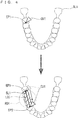
- Fig. 4 is a view illustrating the method for setting the tomographic layer of interest LOI.
- the display 32 displays a schematic diagram IL1 that simulates a lower jaw as a designation image for designating the tomographic layer of interest LOI.
- a plurality of teeth are also drawn in the schematic diagram IL1.
- the operator designates two end points EP1, EP2 with respect to the schematic diagram IL1 displayed on the display 32 using a cursor (or mouse pointer) CU1.
- the end points EP1, EP2 may be designated by moving the cursor (or mouse pointer) CU1 through a drag operation.
- the positions of the end points EP1, EP2 correspond to the positions of two points in the XY-plane in the real space.
- the linear tomographic plane of interest SL1 having end points EP1, EP2 at both ends is set when the two end points EP1, EP2 are designated (see Fig. 3 ).
- the end points EP1, EP2 have a width W1 of the tomographic plane of interest SL1.
- the end points EP1, EP2 are not necessarily set to both ends.
- the tomographic plane of interest SL1 having any width may be set on a straight line passing through the end points EP1, EP2.
- the linear tomographic layer of interest LOI is set in the XY-plane having the required thickness TN1 in the normal direction DN1 based on the tomographic plane of interest SL1.
- a length (a vertical width W2 corresponding to the height when the LOI is viewed from the normal direction DN1 in Fig. 3 ) in a depth direction (corresponding to the Z-axis direction of the real space) of the tomographic layer of interest LOI) is also set appropriately.
- the vertical width W2 of the tomographic layer of interest LOI may be designated by the operator, or automatically determined according to the physical characteristics (such as the gender, the age, the height, and the weight) or the imaging site of the subject M1 by the tomographic layer-of-interest setting unit 304.
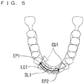
- Fig. 5 is a view illustrating the method for setting the tomographic layer of interest LOI.
- the tomographic layer of interest LOI is set to the shape extending linearly in the XY-plane.
- the tomographic layer of interest LOI may be set to a curved shape.
- the tomographic layer-of-interest setting unit 304 sets the tomographic plane of interest SL1 to the curved shape according to the movement trajectory of the cursor CU1.
- the tomographic layer-of-interest setting unit 304 may set the tomographic layer of interest LOI along the tomographic plane of interest extending in the curved manner based on the tomographic plane of interest SL1. When a plurality of points are designated by the cursor CU1, curve interpolation between them may automatically be performed.
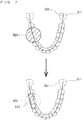
- Fig. 6 is a view illustrating the method for setting the tomographic layer of interest LOI.
- the operator sets the tomographic layer of interest LOI to any position.
- a plurality of candidate regions that are candidates of the tomographic layer of interest LOI are previously specified, and the operator selects the tomographic layer of interest LOI from among these candidate regions.
- seven candidate regions CR1 are previously determined in the schematic diagram IL1 of the jaw displayed on the display 32, and each candidate region CR1 is displayed by a broken line.
- the tomographic layer-of-interest setting unit 304 sets the selected candidate region CR1 to the tomographic layer of interest LOI.
- the designation operation of the tomographic layer of interest LOI can easily be performed.
- Fig. 7 is a view illustrating the method for setting the imaging region ROI and the tomographic layer of interest LOI.
- the operator directly designates the tomographic layer of interest LOI on the designation image.
- the tomographic layer-of-interest setting unit 304 automatically sets the tomographic layer of interest LOI according to the imaging region ROI.
- the imaging region ROI may be set as follows. That is, the operator designates the position of the imaging region ROI (for example, the center position of the imaging region ROI) and the radius of the imaging region ROI using the cursor CU1 or the like.
- the tomographic layer-of-interest setting unit 304 sets the imaging region ROI having the designated radius at the designated position.
- the radius of the imaging region ROI may be designated by numerical input through the keyboard or the like, or designated by the drag operation using the mouse. Circular frames having various radii indicating the size of the imaging region ROI may previously be prepared, and the operator may select the frame having the specific radius from among the circular frames.
- the imaging region setting unit 302 may set the imaging region ROI at the position where the selected frame is disposed according to the disposition of the selected frame at the required position on the schematic diagram IL1.
- the imaging region setting unit 302 automatically sets the tomographic layer of interest LOI according to a predetermined rule for the set imaging region ROI.
- the tomographic layer-of-interest setting unit 304 may set the tomographic layer of interest LOI based on a dental arch DA1 defined along the jaw.
- a dental arch DA1 defined along the jaw.
- the dental arch DA1 curved into a U-shape is defined in the schematic diagram IL1 of the jaw, and that the imaging region ROI is set so as to include the dental arch DA1.
- the tomographic layer-of-interest setting unit 304 may automatically set the tomographic layer of interest LOI along a part of the dental arch DA1 included in the imaging region ROI.
- the linear tomographic layer of interest LOI When the linear tomographic layer of interest LOI is set from the curved dental arch DA1, for example, a point on the portion of the dental arch DA1 of the imaging region ROI is taken as a representative point, and the tomographic layer of interest LOI may be set on a tangential line on the representative point of the dental arch DA1.
- the shape of the imaging region ROI is a circle as viewed from the z-axis direction (+z-direction or -z-direction)
- one point on the portion may be set to the center of the circle of the imaging region ROI.
- the tomographic layer of interest LOI may be set on a line obtained by translating the tangential line in a buccolingual direction.
- the tomographic layer of interest LOI may be set on a line that is slightly translated in a lingual direction so as to pass through substantially the entire center of the target teeth. Two points on a portion of the dental arch DA1 in the imaging region ROI may be selected, and the tomographic layer of interest LOI may be set on a straight line connecting the two points.
- the size of the imaging region ROI may be variable, and the size of the frame indicating the imaging region ROI may be changed by the drag operation using the mouse or the like.
- an X-ray restriction amount of the X-ray regulating unit 44 may be changed according to the change in the size of the imaging region ROI.
- the shape of the imaging region ROI viewed in the z-direction may not be a perfect circle.
- the imaging region ROI may have an elliptical shape in which a major diameter is aligned with a row of teeth.
- the ROI three-dimensionally has an elliptical cylindrical shape.
- the rotation center of the X-ray generator 42 and the X-ray detector 52 is placed at the center of the ellipse in accordance with the ROI having the elliptical cross-section, and the X-ray regulating unit 44 controls the spread of the X-ray beam.
- the spread of the X-ray beam is narrowed when the center axis X-ray of the X-ray beam intersects a minor axis, and the spread of the X-ray beam is widened when the center axis X-ray of the X-ray beam intersects the major axis.
- the curved tomographic layer of interest LOI of the tomographic layer-of-interest setting unit 304 may be set based on the curved dental arch DA1.
- a curved portion of the dental arch DA1 in the imaging region ROI may be set to the tomographic plane of interest SL1, and a region having a predetermined thickness based on the curved portion may be set to the tomographic layer of interest LOI.
- Fig. 8 is a view illustrating the method for setting the tomographic layer of interest LOI.
- a panoramic X-ray image IL2 obtained by previously performing panoramic imaging of the jaw of the subject M1 is used as the designation image.
- the panoramic X-ray image IL2 is displayed on the display 32, and the tomographic layer of interest LOI or the imaging region ROI is set on the panoramic X-ray image IL2.
- Each pixel constituting the panoramic X-ray image IL2 has information about a coordinate position on the real space. For this reason, the coordinate position corresponding to the specific portion in the real space is specified when a specific portion on the panoramic X-ray image IL2 is selected using a cursor CU2.
- the cursor CU2 includes two straight lines orthogonal to each other.
- the operator aligns the intersection of the two straight lines with the site to be observed, namely, the tomographic layer of interest LOI, and performs the operation (such as a mouse click operation) to specify the position.
- the imaging region setting unit 302 appropriately sets the linear or curved tomographic layer of interest LOI.
- the methods for setting the tomographic layer of interest LOI in Figs. 4 to 8 is merely illustrative.
- the present invention is not limited to the methods in Figs. 4 to 8 , and the tomographic layer of interest LOI may be set by another method.
- a plurality of X-ray projection images (fluoroscopic images) obtained by irradiating the subject M1 with the X-ray beam BX1 from a plurality of directions may be used as the designation image for designating the imaging region ROI or the tomographic layer of interest LOI.
- the coordinate position on the real space corresponding to the designated position can be specified by receiving the designation of the position of the imaging region ROI or the tomographic layer of interest LOI on two fluoroscopic images obtained by imaging the subject M1 from two directions.
- the technique described in Japanese Patent Application Laid-Open No. 2004-329293 can be used when the coordinate position in the real space is specified from the fluoroscopic images in the two directions.
- the imaging region setting unit 302 may set the imaging region ROI according to the tomographic layer of interest LOI. At this point, the imaging region ROI may be set such that the imaging region setting unit 302 includes the previously-set tomographic layer of interest LOI.
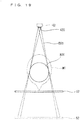
- Fig. 9 is a view illustrating a relationship between a magnification factor and resolution in the X-ray projection image.
- Fig. 9 is a plan view schematically illustrating the X-ray generator 42 and the X-ray detector 52 when viewed from the +Z-side (in -Z-direction view). As illustrated in Fig. 9 , the X-ray beam BX1 spreading in a fan shape is emitted from the X-ray tube of the X-ray generator 42. For this reason, the imaging region ROI is enlarged and projected onto the X-ray detector 52.
- the magnification factor of the X-ray projection image (hereinafter, referred to as a "projection magnification factor") projected onto the X-ray detector 52 is determined by a distance from the X-ray generator 42 to the imaging region ROI and a distance from the imaging region ROI to the X-ray detector 52.
- a projection magnification factor the magnification factor of the X-ray projection image projected onto the X-ray detector 52.
- X-ray detector 52 In the X-ray detector 52, many X-ray detection elements are arrayed in the detection surface. Thus, the resolving power of the X-ray detector 52 is fixed, so that the resolution of the X-ray projection image can be improved by increasing the projection magnification factor.
- a focal point of the X-ray beam BX1 emitted from the X-ray generator 42 is not a point strictly, but a focal plane 420 having a certain size.
- An anode (focal plane 420) of the actual X-ray tube is inclined with respect to an X-ray irradiation axis.
- the anode is illustrated so as to be perpendicular to the X-ray irradiation axis.
- an X-ray flux passing through the specific point in the X-ray beam BX1 emitted from the focal plane 420 is projected onto the detection surface of the X-ray detector 52 with constant spread. That is, the X-ray beam BX1 emitted from the focal plane 420 causes blurring on the X-ray projection image.
- the projection magnification factor increases, a degree of blurring also increases, and resultantly the resolution (sharpness) of the X-ray projection image decreases.
- the projection magnification factor is desirably decreased as much as possible.
- the X-ray detector 52 is caused to approach the imaging region ROI as much as possible, or the X-ray generator 42 is moved away from the imaging region ROI as much as possible.
- the X-ray detector 52 when the X-ray detector 52 is caused to approach the imaging region ROI, the X-ray detector 52 may come into contact with the subject M1.
- the X-ray generator 42 When the X-ray generator 42 is moved away from the imaging region ROI, there is a possibility that the X-ray generation unit 40 accommodating the X-ray generator 42 collides with another member (for example, the post 70) of the imaging unit 20 or another member other than the imaging unit 20 disposed in the periphery.
- the imaging trajectory setting unit 306 sets the imaging trajectory so as to decrease the projection magnification factor as much as possible while preventing the X-ray detector 52 from contacting with the subject M1 and preventing the X-ray generation unit 40 of the X-ray generator 42 from colliding with another member during the X-ray imaging.
- a specific method for setting the imaging trajectory will be described below.
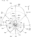
- Fig. 10 is a view illustrating an example of the X-ray imaging.
- the X-ray imaging in Fig. 10 is CT imaging in which the X-ray generator 42 and the X-ray detector 52 are turned by 180° around the jaw of the subject M1. At this point, the vicinity of the front teeth of the subject M1 is set to the imaging region ROI, and the tomographic layer of interest LOI is set to a linear region along the dental arch DA1.
- the X-ray generator 42 is turned by 180° from a position 42p0 on the right side of the head of the subject M1 to a position 42p4 on the left side of the head after passing through a rear side of the head.
- the X-ray detector 52 passes through a front side of the head from a position 52p0 on the left side of the head of the subject M1, and is turned by 180° to a position 52p4 on the right side of the head.
- each of the X-ray generator 42 and the X-ray detector 52 is rotated at a constant rotation radius around a center point CP1 of the imaging region ROI. That is, the X-ray generator 42 and the X-ray detector 52 may be moved on normal imaging trajectories NT42, NT52.
- the X-ray generator 42 follows the normal imaging trajectory NT42
- the X-ray detector 52 follows the normal imaging trajectory NT52.
- the imaging trajectory setting unit 306 sets imaging trajectories PT42, PT52 in which, when the imaging trajectory setting unit 306 confronts the tomographic layer of interest LOI in the imaging region ROI, the projection magnification factor is smaller than that of non-confrontation. More specifically, when the X-ray generator 42 confronts the tomographic layer of interest LOI, as compared with the non-confrontation, the X-ray generator 42 is moved farther away from the tomographic layer of interest LOI, and the X-ray detector 52 is caused to approach the tomographic layer of interest LOI.
- the imaging trajectories PT42, PT52 are referred to as a magnification factor adjustment imaging trajectory
- the X-ray generator 42 follows the magnification factor adjustment imaging trajectory PT42
- the X-ray detector 52 follows the magnification factor adjustment imaging trajectory PT52.
- the CT imaging with the magnification factor adjustment imaging trajectories PT42, PT52 is referred to as magnification factor adjustment CT imaging.
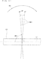
- Fig. 11 is a view illustrating a center axis X-ray CBX1 incident on the tomographic layer of interest LOI.
- the X-ray passing through the turning center axis RA1 is set to the center axis X-ray CBX1.
- the center axis X-ray CBX1 is the X-ray matched with the irradiation axis of the X-ray beam BX1.
- the confrontation of the X-ray generator 42 with the tomographic layer of interest LOI means a state in which the center axis X-ray CBX1 is incident on the tomographic layer of interest LOI at substantially right angles.
- incident at substantially right angles means the state in which an incident angle ANG1 of the center axis X-ray CBX1 with respect to the tomographic layer of interest LOI is in a range from 85° to 95°, and in particular, the state in which the center axis X-ray CBX1 is incident at right angles means the state in which the incident angle ANG1 becomes 90°.
- the incident angle ANG1 means an angle around a turning direction RD1 from a center line LL1 to the center axis X-ray CBX1 when the center line LL1 passing through the center of the tomographic layer of interest LOI is defined as viewed from the upper side in the Z-axis direction, namely, in Z-direction view.
- the X-ray generator 42 rotates clockwise with respect to the subject M1 as viewed from the +Z-side, that is, in -Z-direction view.
- the incident angle ANG1 is a clockwise angle from the center line LL1 to the center axis X-ray CBX1.
- the tangential line on the tomographic layer of interest LOI and at any point (for example, a barycentric point of the curve) on the curve along the tomographic layer of interest LOI is set to the center line LL1, and the angle between the center axis X-ray CBX1 and the center line LL1 is set to the incident angle ANG1.
- each of the positions 42p0 to 42p4 of the X-ray generator 42 is the position of the X-ray generator 42 where the incident angle ANG1 becomes 0°, 45°, 90°, 135°, and 180°. That is, the state in which the X-ray generator 42 confronts the tomographic layer of interest LOI (the state in which the irradiation axis of the X-ray beam BX1 is incident on the tomographic layer of interest LOI in the confronting manner) becomes the position 42p2.
- the state in which the X-ray generator 42 does not confront the tomographic layer of interest LOI (the state in which the irradiation axis of the X-ray beam BX1 is not incident on the tomographic layer of interest LOI in the confronting manner) becomes positions 42p0, 42p1, 42p3, 42p4.
- the position 42p2 in the confronting state is compared to the positions 42p0, 42p1,42p3 and 42p4 in the state, the position 42p2 in the confronting state is a position farther from the tomographic layer of interest LOI than the other positions. That is, the position 42p2 is set outside the normal imaging trajectory NT42 of the X-ray generator 42.
- the position 52p2 of the X-ray detector 52 in the confronting state is closer to the tomographic layer of interest LOI than the positions 52p0, 52p1, 52p3, 52p4 in the non-confronting state.
- the position 52p2 is set outside the normal imaging trajectory NT52 of the X-ray detector 52.
- the X-ray generator 42 In the CT imaging, until the X-ray generator 42 reaches the position 42p2 of the confronting state after passing through the position 42p1 where the incident angle ANG1 becomes 45°, the X-ray generator 42 is gradually moved away from the tomographic layer of interest LOI, and the X-ray detector 52 is gradually caused to approach the tomographic layer of interest LOI. Until the X-ray generator 42 reaches the position 42p3 where the incident angle ANG1 becomes 135° from the position 42p2 of the confronting state, the X-ray generator 42 is gradually caused to approach the tomographic layer of interest LOI, and the line X-ray detector 52 is gradually moved away from the tomographic layer of interest LOI.
- the position 42p1 to the position 42p3 are different from those of the normal imaging trajectory NT42, and other positions are matched.
- the position 52p1 to the position 52p3 are different from those of the normal imaging trajectory NT52, and other positions are matched.
- Fig. 12 is a view illustrating a fluctuation in the projection magnification factor according to the turning angles of the X-ray generator 42 and the X-ray detector 52.
- the projection magnification factor is kept constant until the incident angle ANG1 reaches 45°, and the projection magnification factor decreases gradually until the incident angle ANG1 becomes 90° after exceeding 45°.
- the projection magnification factor is minimized when the incident angle ANG1 is 90°.
- the projection magnification factor increases gradually until the incident angle ANG1 reaches 135° after the incident angle ANG1 exceeds 90°, and the projection magnification factor is kept constant after the incident angle ANG1 exceeds 135°. That is, the magnification factor decreased in the confronting state when the state in which the X-ray generator 42 confronts the tomographic layer of interest LOI (when the X-ray generator 42 is located at the position 42p2) and the state in which the X-ray generator 42 does not confront the tomographic layer of interest LOI (for example, when the X-ray generator 42 is located at the positions 42p0, 42p1,42p3, 42p4) are compared to each other.
- the magnification factor may be minimized only when the incident angle ANG1 is 90°.
- the minimized magnification factor may have a width. That is, the magnification factor may be maintained at the same minimum magnitude for a certain period from the timing at which the incident angle ANG1 is slightly less than 90°, through the timing at which the incident angle ANG1 is exactly 90°, and to the timing at which the incident angle ANG1 slightly exceeds 90°.
- the imaging trajectory setting unit 306 sets the imaging trajectories PT42, PT52 of the X-ray generator 42 and the X-ray detector 52.
- the imaging controller 80 moves the X-ray generator 42 and the X-ray detector 52 along the imaging trajectories PT42, PT52 by controlling the operations of the turning drive unit 642 and the XY-direction movement drive unit 644. That is, the imaging controller 80 controls the XY-direction movement drive unit 644 according to the incident angle ANG1 while changing the incident angle ANG1 by controlling the operation of the turning drive unit 642. Consequently, the imaging controller 80 relatively decreases the projection magnification factor in the confronting state when the confronting state and the non-confronting state are compared to each other.
- the turning is started from the position where the incident angle ANG1 becomes 0°.
- the turning is not necessarily started from the position where the incident angle ANG1 becomes 0°.
- the turning of the X-ray generator 42 may be started from the position where the incident angle ANG1 becomes an angle larger than 0° or the position where the incident angle ANG1 becomes an angle smaller than 0° (the position where the center axis X-ray CBX1 is emitted on the opposite side to the confronting side with respect to the tomographic layer of interest LOI).
- the rotation of the X-ray generator 42 may be started from the near side in the rotational direction with respect to the position 42p0, and the emission of the X-ray beam BX1 may be started after the X-ray generator 42 reaches the position 42p0.
- the turning center axis RA1 that is the turning center of the X-ray generator 42 and the X-ray detector 52. While the X-ray generator 42 moves from the position 42p0 to the position 42p1, and while the X-ray generator 42 moves from the position 42p3 to the position 42p4, the turning center axis RA1 is set to the center point CP1. On the other hand, while the X-ray generator 42 moves from the position 42p1 to the position 42p3, as indicated by an arrow D1 in Fig. 10 , the turning center axis moves on a circular trajectory in which the X-ray generator 42 moves away from the center point CP1 and returns to the center point CP1.
- the X-ray generator 42 and the X-ray detector 52 can be moved on the imaging trajectories PT42, PT52 by moving the shaft 66 on the trajectory of the turning center axis RA1 in Fig. 10 .
- the shaft 66 is not necessarily matched with the turning center axis RA1.
- the technique described in Japanese Patent Application Laid-Open No. 2007-29168 can also be applied to the present application. That is, while the shaft 66 is rotated, the shaft 66 is moved along a circumference of a predetermined radius centered on the center point CP1 of the imaging region ROI in the XY-plane.
- the X-ray generator 42 and the X-ray detector 52 may be turned around the turning center axis RA1 matched with the center point CP1.
- the turning center axis RA1 is set at a position different from the shaft 66 that is the mechanical turning axis.
- the rotational movement and the movement in the XY-plane of the X-ray generator 42 and the X-ray detector 52 are performed by the rotation about the Z-axis of the shaft 66 of the turning arm 62 and the movement in the XY-plane.
- the setting of the imaging trajectories PT42, PT52 of the X-ray generator 42 and the X-ray detector 52 is equivalent to the setting of the position in the XY-plane of the shaft 66 according to the rotation amount of the shaft 66.
- the description of the movement of the turning center axis RA1 will be further supplemented.
- the movement turning center axis RA1 moves as the rotation center at any time while the X-ray generator 42 and the X-ray detector 52 move along the magnification factor adjustment imaging trajectories PT42, PT52.
- an incident angle at which the incident angle ANG1 is an intermediate angle between 45° and 90° is set to an incident angle ANG1a
- an incident angle at which the incident angle ANG1 is 90° is set to an incident angle ANG1b.
- the center axis X-ray CBX1 at the incident angle ANGla is set to a center axis X-ray CBX1A (not illustrated), and the center axis X-ray CBX1 at the incident angle ANGlb is set to a center axis X-ray CBX1B (not illustrated).
- the position of the turning center axis RA1 at the incident angle ANGla takes the position of, for example, RAla in Fig. 10
- the position of the turning center axis RA1 at the incident angle ANGlb takes the position of, for example, RA1b in Fig. 10 .
- the center axis X-ray CBX1 at the incident angle ANGla is a center axis X-ray CBXla matched with the center axis X-ray CBX1A in an incident angle manner
- the center axis X-ray CBX1 at the incident angle ANG1b is a center axis X-ray CBXlb matched with the center axis X-ray CBX1B in the incident angle manner.
- the incident angle is caused to correspond to the incident angle in the normal CT imaging in which the turning center is fixed to one point, and the approach and the movement away of the X-ray generator 42 and the X-ray detector 52 are changed with respect to the imaging region during the imaging, which allows the magnification factor adjustment CT imaging to be performed.
- the position RA1b of the turning center axis RA1 at the incident angle of 90° is located at a peak separated from the center point CP1.
- the degree of separation of the position RAla from the center point CP1 is equal to the degree between the position RA10 and the position RA1b. That is, although the position RAla is separated farther from the center point CP1 than the position RA10, the degree of the position RAla is not as large as that of the position RA1b.
- the position of the turning center axis RA1 moves on the axial line of the center axis X-ray CBX1 at each timing at which the incident angle changes.
- the position of the turning center axis RA1 gradually changes such that a degree of separation of the turning center axis RA1 from the center point CP1 peaks while the center axis X-ray CBX1 is incident on the tomographic layer of interest LOI in the confronting manner.
- the degree of separation is maintained so as to be maximized not only in the state in which the center axis X-ray CBX1 is incident on the tomographic layer of interest LOI in the confronting manner, but also in the period of good incident angles close to the confronting state.
- the projection magnification factor is decreased when the X-ray generator 42 confronts the tomographic layer of interest LOI, so that the blurring caused by the size of the focal plane 420 can be reduced on the X-ray projection image when the tomographic layer of interest LOI is projected from the front surface. That is, the X-ray projection image can be acquired with high resolution when the tomographic layer of interest LOI is projected from the front surface.
- the image quality of the tomographic image obtained when the image processor 308 reconstructs the tomographic layer of interest LOI can be improved.
- the X-ray detector 52 is caused to approach the tomographic layer of interest LOI by limiting to a part of the entire turning range in which the X-ray generator 42 and the X-ray detector 52 are turned, which prevents the X-ray detector 52 from contacting with the subject M1.
- the X-ray generator 42 is moved away from the tomographic layer of interest LOI by limiting to a part of the entire turning range, so that the X-ray generator 42 or the X-ray generation unit 40 accommodating the X-ray generator 42 and one end of the turning arm 62 supporting the X-ray generation unit 40 can be prevented from colliding with another member (such as the post 70).
- the X-ray generation controller 810 controls the operation of the X-ray regulating unit 44 according to the movement of the X-ray generator 42 away from the tomographic layer of interest LOI during the turning, so that the emission range of the X-ray beam BX1 (a spread angle (fan angle) about the Z-axis of the X-ray beam BX1) may be decreased. Consequently, the range wider than the imaging region ROI can be prevented from being irradiated with the X-ray beam BX1, so that an X-ray exposure dose of the subject M1 can be reduced.
- the setting of the imaging region ROI is received such that the imaging region ROI includes at least a part of the dental arch DA1, and the tomographic layer of interest LOI may be set along a part of the dental arch DA1 set in the imaging region ROI. Consequently, because the tomographic image along the dental arch DA1 can be acquired, the tomographic image suitable for a dental diagnosis can be acquired.
- the dental arch DA1 is unevenly distributed in front of the head of the subject M1, and extends along a front edge of the head.
- the setting of the tomographic layer of interest LOI along the dental arch can cause the X-ray detector 52 to approach the head when the X-ray generator confronts the tomographic layer of interest LOI.
- the high-resolution X-ray tomographic image can easily be acquired.
- Fig. 13 is a view illustrating an example of the X-ray imaging.
- the X-ray imaging in Fig. 13 is CT imaging in which the vicinity of a right molar in the jaw of the subject M1 is set to the imaging region ROI.
- the X-ray generator 42 is turned by 180° from the position 42p0 on the right rear side of the head of the subject M1 to the position 42p4 on the left front side of the head
- the X-ray detector 52 is turned by 180° from the position 52p0 on the left front side of the head of the subject M1 to the position 52p4 on the right rear side of the head.
- the X-ray generator 42 confronts the tomographic layer of interest LOI, namely, when the center axis X-ray CBX1 emitted from the X-ray generator 42 is incident on the tomographic layer of interest LOI at right angles, the X-ray generator 42 passes through the position 42p2 where the X-ray generator 42 is moved away from the tomographic layer of interest LOI, and the X-ray detector 52 passes through the position 52p2 where the X-ray detector 52 approaches the tomographic layer of interest LOI. Consequently, the projection magnification factor can be decreased in the confronting state.
- the tomographic layer of interest LOI is set along the front teeth of the jaw.
- a convex nose is located on one side in the normal direction of the tomographic layer of interest LOI.
- the imaging trajectory setting unit 306 set the imaging trajectory PT52 such that the X-ray detector 52 does not contact with the nose.
- the tomographic layer of interest LOI is set along the right molar in the jaw of the subject M1.
- a concave portion such as the nose does not exist, but only a cheek exists.
- the imaging trajectory setting unit 306 can set the imaging trajectory PT52 such that the X-ray detector 52 is closer to the tomographic layer of interest LOI as compared to the case of the CT imaging in Fig. 10 .
- the CT imaging in Figs. 10 and 13 is the CT imaging in which the X-ray generator 42 and the X-ray detector 52 are turned by 180°.
- the turning angles of the X-ray generator 42 and the X-ray detector 52 are not limited to 180°.
- Fig. 14 is a view illustrating an example of the X-ray imaging.
- the X-ray imaging in Fig. 14 is the CT imaging, in which the vicinity of the right molar in the jaw is set to the imaging region ROI and a part of the dental arch DA1 is included in the imaging region ROI.
- the tomographic layer of interest LOI is the region extending linearly along the tangential line of a part of the dental arch DA1 included in the imaging region ROI.
- the X-ray generator 42 is turned by 360° from the position 42p0 at the right rear side of the head of the subject M1 to the position 42p0 after passing through each of the positions 42p1 to 42p7.
- the X-ray detector 52 is turned by 360° from the position 52p0 on the left front side of the head of the subject M1 to the position 52p0 after passing through each of the positions 52p1 to 52p7.
- the nose of the head is expressed as 12 o'clock
- the back of the head is expressed as 6 o'clock
- a right ear is expressed as 3 o'clock
- a left ear is expressed as 9 o'clock.
- the center axis X-ray CBX1 confronts the tomographic layer of interest LOI while being orthogonal to the tomographic layer of interest LOI when the subject M1 is irradiated with the X-ray beam BX1 from the right side of the subject M1 (specifically, between 12 o'clock and 3 o'clock, and the right side when the entire head is roughly divided into the left and the right) (when the X-ray generator 42 passes through the position 42p2 and the X-ray detector 52 passes through the position 52p2), and when the subject M1 is irradiated with the X-ray beam BX1 from the left side of the subject M1 (specifically, between 6 o'clock and 9 o'clock, and the left side when the entire head is roughly divided into the left and the right) (when the X-ray generator 42 passes through the position 42p6 and the X-ray detector 52 passes through the position 52p6).
- the X-ray generator 42 In the CT imaging, when the X-ray generator 42 confronts the tomographic layer of interest LOI, the X-ray generator 42 passes through the positions 42p2, 42p6.
- the positions 42p2, 42p6 are positions moved farther away from the tomographic layer of interest LOI than the position (for example, the positions 42p0, 42p1,42p3 to 42p5, 42p7) of the X-ray generator 42 when the X-ray generator 42 does not confront the tomographic layer of interest LOI.
- the X-ray detector 52 passes through the positions 52p2, 52p6.
- the positions 52p2, 52p6 are positions moved farther away from the tomographic layer of interest LOI than the position (for example, the positions 52p0, 52p1, 52p3 to 52p5, 52p7) of the X-ray detector 52 when the X-ray generator 42 does not confront the tomographic layer of interest LOI. Consequently, when the X-ray generator 42 confronts the tomographic layer of interest LOI, the projection magnification factor is decreased as compared with the case where the X-ray generator 42 does not confront the tomographic layer of interest LOI.
- the confronting state when the X-ray generator 42 passes through the position 42p2 is set to a first confronting state
- the confronting state when the X-ray generator 42 passes through the position 42p6 is set to a second confronting state.
- the position 52p2 of the X-ray detector 52 in the first confronting state is closer to the tomographic layer of interest LOI than the position 52p6 of the X-ray detector 52 in the second confronting state.
- the X-ray detector 52 can be caused to approach the imaging region ROI as compared to the case of the irradiation from the right side (between 12 o'clock and 3 o'clock) when the subject M1 is irradiated with the X-ray beam BX1 from the left side (between 6 o'clock and 9 o'clock) of the subject M1.
- the trajectories PT42, PT52 can be corrected when another mechanical element interferes with the turning of the X-ray generator 42 and the X-ray detector 52.
- the trajectories PT42, PT52 can appropriately be corrected so as to avoid the post 70.
- the tomographic layer of interest LOI set in the imaging region ROI is not limited to one.
- Fig. 15 is a view illustrating an example of the X-ray imaging.
- the X-ray imaging in Fig. 15 is the CT imaging, in which the entire jaw of the subject M1 is set to the imaging region ROI and two tomographic layers of interest LOI1, LOI2 are set inside the imaging region ROI. At this point, the tomographic layers of interest LOI1, LOI2 are set to the left temporomandibular joint and the right temporomandibular joint, respectively.
- the X-ray generator 42 is turned by 360° from the position 42p0 in front of the head of the subject M1 to the position 42p0 after passing through the positions 42p1 to 42p7.
- the X-ray detector 52 is turned by 360° from the position 52p0 on the rear side of the head of the subject M1 to the position 52p0 after passing through the positions 52p1 to 52p7.
- the position 42p2 through which the X-ray generator 42 passes is farther from the tomographic layer of interest LOI1 as compared with the position (for example, positions 42p0, 42p1,42p3 to 42p5, 42p7) in the non-confronting state.
- the position 52p2 through which the X-ray detector 52 passes is closer to the tomographic layer of interest LOI than the position (for example, positions 52p0, 52p1, 52p3 to 52p5, 52p7) in the non-confronting state.
- the projection magnification factor can relatively decreased smaller than the non-confronting state.
- the position 42p6 through which the X-ray generator 42 passes when the X-ray generator 42 confronts a tomographic layer of interest LOI2 is farther from the tomographic layer of interest LOI2 than the positions (for example, the positions 42p0, 42p1, 42p3 to 42p5, 42p7) in the non-confronting state.
- the position 55p6 through which the X-ray detector 52 passes is closer to the tomographic layer of interest LOI2 than the position (for example, positions 52p0, 52p1, p3 to 52p5, 52p7) in the non-confronting state. Consequently, the projection magnification factor can be decreased when the X-ray generator 42 confronts the tomographic layer of interest LOI2.
- the position 42p6 is the position when the X-ray generator 42 does not confront the tomographic layer of interest LOI1. It is also assumed that the position 42p2 is closer to the tomographic layer of interest LOI1 than the position 42p6. That is, the position 42p2 through which the X-ray generator 42 passes when confronting the tomographic layer of interest LOI1 is not necessarily farther from the tomographic layer of interest LOI1 than all the positions through which the X-ray generator 42 passes when the X-ray generator 42 does not confront the tomographic layer of interest LOI1.
- the position 42p2 may be farther from the tomographic layer of interest LOI1 than at least a part of all the positions through which the X-ray generator 42 passes when the X-ray generator 42 does not confront the tomographic layer of interest LOI1.
- the position 52p6 is the position of the X-ray detector 52 when the X-ray generator 42 does not confront the tomographic layer of interest LOI, but it is assumed that the position 52p6 is located closer to the tomographic layer of interest LOI than the position 52p2. That is, the position 52p2 may be closer to the tomographic layer of interest LOI1 than at least a part of all the positions through which the X-ray detector 52 passes when the X-ray generator 42 does not confront the tomographic layer of interest LOI1.
- the projection magnification factor is decreased when the X-ray generator 42 confronts the tomographic layer of interest LOI1 while turning on the right side of the subject M1.
- the projection magnification factor may be decreased when the X-ray generator 42 confronts the tomographic layer of interest LOI1 while turning on the left side of the subject M1 (when the X-ray generator 42 passes through the side opposite to the position 42p2).
- the projection magnification factor is decreased when the X-ray generator 42 confronts the tomographic layer of interest LOI2 while turning on the left side of the subject M1.
- the projection magnification factor may be decreased when the X-ray generator 42 confronts the tomographic layer of interest LOI2 while turning on the left side of the subject M1 (that is, when the X-ray generator 42 passes through the side opposite to the position 42p6).
- the support 60 is elevated or lowered with respect to the head MH by the relative movement, which allows the X-ray irradiation location to be changed in the Z-axis direction.
- the plurality of imaging regions located at different height positions can continuously be imaged such that one of the tooth rows of the upper jaw and the lower jaw is continuously imaged after the other is imaged.
- different regions of the dental arch may be set to the imaging target in each height position such that a front-tooth region is set in the upper jaw and a molar region is set in the lower jaw.
- Fig. 16 is a view illustrating an example of the X-ray imaging.
- the X-ray imaging in Fig. 16 is tomosynthesis imaging in which the X-ray generator 42 and the X-ray detector 52 are turned by an angle less than 180° around the head of the subject M1.
- the turning angle may be set to 90° or 60°. Any angle less than 180° may be set by the operation, and any angle between 90° and 60° may be set by the operation.
- the tomosynthesis imaging as illustrated in Fig.
- the X-ray projection image is acquired by rotating the X-ray generator 42 and the X-ray detector 52 to the left and right by a required angle around the incident angle ANG1 at which the X-ray generator 42 confronts the tomographic layer of interest LOI to be observed by an observer.
- an X-ray tomographic images having relatively high quality can be acquired by reconstruction with respect to the tomographic layer of interest LOI. Since the X-ray irradiation less than only 180° is performed, the tomosynthesis imaging has an advantage that an imaging time can be shortened while the X-ray exposure dose of the subject M1 is reduced as compared with the CT imaging.
- the imaging region ROI is set in the vicinity of the front teeth of the jaw of the subject M1, and the tomographic layer of interest LOI is set along the portion of the dental arch DA1 included in the imaging region ROI.
- the X-ray generator 42 is turned from the position 42p0 on the right rear side of the subject M1 to the position 42p2 on the left rear side
- the X-ray detector 52 is turned from the position 52p0 on the right front side of the subject M1 to the position 52p2 on the left front side.
- the imaging trajectories of the X-ray generator 42 and the X-ray detector 52 are set such that the X-ray generator 42 passes through the position 42p1 and the X-ray detector 52 passes through the position 52p1.
- the position 42p1 of the X-ray generator 42 is farther from the tomographic layer of interest LOI than the position (for example, the positions 42p0, 42p2) of the X-ray generator 42 when the X-ray generator 42 does not confront the tomographic layer of interest LOI.
- the position 52p1 is closer to the tomographic layer of interest LOI than the position (for example, the positions 52p0, 52p2) of the X-ray detector 52 when the X-ray generator 42 does not confront the tomographic layer of interest LOI.
- the setting of the imaging trajectory in this manner decreases the projection magnification c factor during the confrontation, so that the high-quality X-ray tomographic image can be generated with respect to the tomographic layer of interest LOI.
- Fig. 17 is a flowchart illustrating the operation of the X-ray tomography apparatus 10. In the following description, it is assumed that positioning of the subject M1 in the imaging unit 20 is already completed.
- the information processor 30 causes the display 32 to display the designation image for designating the tomographic layer of interest LOI or the imaging region ROI (step S101).
- the designation image is a schematic diagram IL1 in which the site of interest is drawn, or a transmission image (such as a panoramic X-ray image IL2) obtained by the X-ray imaging of the subject M1.
- the information processor 30 receives an operation to designate a skeleton size (step S102). For example, when the operator inputs the physical characteristics (such as the gender, the age, the height, and the weight) of the subject M1, the information processor 30 acquires the skeleton size corresponding to the input physical characteristics from a predetermined database. In each size, a standard size may be set from statistical data. The acquired skeleton size is used to approximately match the position of the imaging target site of the subject M1 disposed in the imaging unit 20 with the position of the imaging target site in the designation image.
- a skeleton size For example, when the operator inputs the physical characteristics (such as the gender, the age, the height, and the weight) of the subject M1, the information processor 30 acquires the skeleton size corresponding to the input physical characteristics from a predetermined database. In each size, a standard size may be set from statistical data. The acquired skeleton size is used to approximately match the position of the imaging target site of the subject M1 disposed in the imaging unit 20 with the position of the imaging target
- the information processor 30 receives an operation to designate the tomographic layer of interest LOI or the imaging region ROI (step S103).
- the operation to designate the tomographic layer of interest LOI or the imaging region ROI is described with reference to Figs. 4 to 8 .
- each of the tomographic layer of interest LOI and the imaging region ROI may individually be designated.
- the tomographic layer of interest LOI may automatically be set according to the designation of the imaging region ROI.
- the imaging region ROI may automatically be set according to the designation of the tomographic layer of interest LOI.
- the tomographic layer-of-interest setting unit 304 sets the position and the thickness of the tomographic layer of interest LOI based on the designation operation received in step S103.
- the imaging trajectory setting unit 306 determines the imaging trajectories PT42, PT52 of the X-ray generator 42 and the X-ray detector 52 based on the position and the thickness of the tomographic layer of interest set in step S104 (step S105). Specifically, as described above with reference to Figs. 10 to 16 , the imaging trajectory setting unit 306 determines the imaging trajectories PT42, PT52 such that the projection magnification factor when the X-ray generator 42 confronts the tomographic layer of interest LOI is smaller than the projection magnification factor when the X-ray generator 42 does not confront the tomographic layer of interest LOI.
- a prohibited space in which the entry of the X-ray detector 52 is prohibited may previously be defined in the real space where the subject M1 is disposed.
- the imaging trajectory setting unit 306 may set the imaging trajectory PT52 such that the X-ray detector 52 does not enter the prohibited space.
- the prohibited space may be expanded or reduced as appropriate based on the physical characteristics of the subject M1, such as the skeletal data set in step S102.
- a movable space through which the X-ray generator 42 can pass may previously be defined in the imaging unit 20.
- the imaging trajectory setting unit 306 may set the imaging trajectory PT42 such that the X-ray generator 42 moves in the movable space.
- step S105 when the imaging trajectories PT42, PT52 are determined, the imaging unit 20 performs the X-ray imaging (step S106). Specifically, data of the imaging trajectories PT42, PT52 are sent to the imaging controller 80. Based on the data, the turning controller 802 controls the operation of the turning drive unit 642, and the XY-direction movement controller 804 controls the operation of the XY-direction movement drive unit 644.
- the imaging unit 20 captures the X-ray projection image of the imaging region ROI projected on the detection surface of the X-ray detector 52 at a predetermined frame rate. The captured X-ray projection image is appropriately stored in the storage 31 or the like of the information processor 30.
- the image processor 308 performs reconstruction arithmetic processing on the plurality of X-ray projection images acquired in step S106 (step S107). Specifically, the image processor 308 generates three-dimensional volume data of the imaging region ROI by a filter correction back projection method (FBP method), a superposition integration method, or the like. The image processor 308 generates the X-ray tomographic image representing the tomographic layer of interest LOI based on the three-dimensional volume data. Although being concentrated on and around the tomographic layer of interest LOI, three-dimensional image data having a certain thickness can also be generated in the tomosynthesis imaging, and the X-ray tomographic image representing the tomographic layer of interest LOI can be generated.
- FBP method filter correction back projection method
- the projection magnification factor varies among the plurality of X-ray projection images.
- the image size may be converted such that the projection magnification factors are matched with each other between the X-ray projection images. Consequently, parallelization of arithmetic processing is promoted, so that the time necessary for the arithmetic processing can be shortened when an arithmetic processing apparatus (such as a GPU) excellent in parallel processing is used.
- the X-ray tomographic image is generated for the tomographic layer of interest LOI
- the X-ray tomographic image is displayed on the display 32 (step S108).
- the incident angle ANG1 when the X-ray generator 42 starts the approach to the tomographic layer of interest LOI may be an established one, or may be appropriately set according to the tomographic thickness TN1 of the tomographic layer of interest LOI.
- the operation unit 34 or the operation panel 84 may receive the input of the tomographic thickness TN1 from the operator.
- the imaging trajectory unit 306 may set the imaging trajectories PT42, PT52 according to the tomographic thickness TN1 while the tomographic layer-of-interest setting unit 304 of the information processor 30 sets the tomographic layer of interest LOI having the input tomographic thickness TN1.
- the tomographic layer-of-interest setting unit 304 and the operation unit 34 or the operation panel 84 are an example of the configuration of the tomographic thickness designation receiving unit.
- Fig. 23 is a view illustrating the fluctuation in the projection magnification factor according to the incident angle ANG1.
- the projection magnification factor is decreased to P when the X-ray generator 42 confronts (looks straight at) the tomographic layer of interest LOI (when the incident angle ANG1 is 90°).
- the X-ray detector 52 is caused to approach the tomographic layer of interest LOI such that the incident angle AGN1 has the substantially constant low projection magnification factor P between 90° - ⁇ and 90° + ⁇ .
- An incident angle ⁇ s when the X-ray detector 52 starts to approach the tomographic layer of interest LOI and an incident angle ⁇ x when the approach is completed are smaller than 90° - ⁇ .
- An incident angle ⁇ e when the X-ray detector 52 starts to move away from the tomographic layer of interest LOI and an incident angle ⁇ z when the movement away is completed are larger than 90° + ⁇ .
- the tomographic thickness ⁇ increases relatively.
- ⁇ becomes infinite (that is, equivalent to a simple projection image). That is, projection data having the low projection magnification factor can be obtained only when the X-ray generator 42 confronts the tomographic layer of interest LOI.
- the angle ⁇ is brought close to 90°, the tomographic thickness ⁇ decreases relatively. For example, when the angle ⁇ is set to 90°, the projection data for 180° is obtained at the low projection magnification factor, and the tomographic thickness ⁇ is 1/ ⁇ of the limit.
- ⁇ is determined based on the equation (1) when the operator designates the tomographic thickness TN1( ⁇ ) of the tomographic layer of interest LOI, so that the incident angle range 90° - ⁇ to 90° + ⁇ decreasing the projection magnification factor can be determined.
- the imaging trajectory setting unit 306 functions as a controller that determines the incident angle when the X-ray detector 52 is caused to approach the tomographic layer of interest LOI according to the designated tomographic thickness.
- the X-ray tomographic image illustrating the tomographic layer of interest LOI of the designated tomographic thickness can suitably be acquired by determining the suitable incident angle when the magnification factor is changed according to the designated tomographic thickness.
- Fig. 18 is a view illustrating a configuration of an X-ray tomography apparatus 10 according to a modification.
- the subject holder 72 of this modification includes a subject chair 74 on which the subject M1 is seated.
- the XY-direction movement drive unit 644 translates the turning arm 62 in the XY-plane by moving the shaft 66 in the X-axis direction and the Y-axis direction.
- the X-ray generator 42 and the X-ray detector 52 move relative to the subject M1 in the X-axis direction and the Y-axis direction.
- the XY-direction movement drive unit 644 is connected to the subject chair 74, and moves the subject chair 74 in the X-axis direction and the Y-axis direction. Consequently, the subject M1 moves relative to the X-ray generator 42 and the X-ray detector 52 of the turning arm 62 in the X-axis direction and the Y-axis direction.
- the subject chair 74 is moved to move the subject M1 to an appropriate position during the X-ray imaging. That is, when the X-ray generator 42 confronts the tomographic layer of interest LOI, the portion corresponding to the tomographic layer of interest LOI is moved away from the X-ray generator 42, and caused to approach the X-ray detector 52. Consequently, the projection magnification factor can be decreased in the confronting state.
- the turning drive unit 642 rotates the turning arm 62 to turn the X-ray generator 42 and the X-ray detector 52 around the subject M1.
- the turning drive unit 642 may rotate the subject holder to rotate the subject.
- the imaging unit 20 of the embodiment does not necessarily include the turning arm 62.
- the X-ray generation unit 40 and the X-ray detection unit 50 may move along the circumferential direction of the annular member.
- a virtual axis passing through the center of the annular member is the turning center axis RA1.
- the turning center axis RA1 extending in the Z-axis direction is set to the vertical direction.
- the turning center axis RA1 may be set to the horizontal direction.
- the projection magnification factor is decreased during the confrontation by moving both the X-ray generator 42 and the X-ray detector 52 with respect to the tomographic layer of interest LOI.
- the projection magnification factor may be decreased during the confrontation by moving only one of the X-ray generator 42 and the X-ray detector 52 with respect to the tomographic layer of interest LOI.
- Fig. 19 is a view illustrating a state in which the projection magnification factor is reduced by moving only the X-ray detector 52. As illustrated in Fig. 19 , the projection magnification factor decreases by bringing only the X-ray detector 52 close to the imaging region ROI. Consequently, the blurring on the X-ray projection image due to the size of the focal plane 420 can be reduced.
- a movement drive unit (not illustrated) that moves the X-ray detector 52 in the y-direction may be provided in the X-ray detection unit 50.
- the movement drive unit may be constructed with a linear motor type or ball screw type drive unit.
- a movement drive unit that moves the entire X-ray generation unit 40 including the X-ray generator 42 in the y-direction may be provided in the turning arm 62.
- the turning arm 62 is expandably configured.
- Fig. 21 is a schematic side view illustrating a turning arm 62a of the modification.
- one end 620 supporting the X-ray generation unit 40 is configured to be accommodated inside a main body 622 of the turning arm 62.
- the turning arm 62a includes a movement drive unit (not illustrated) that moves the one end 620 in the y-direction.
- the movement drive unit accommodates the one end 620 in the main body 622, whereby the turning arm 62 is shortened and the X-ray generator 42 approaches the X-ray detector 52.
- the movement drive unit takes the one end 620 out of the main body 622, whereby the turning arm 62 is extended to moving the X-ray generator 42 away from the X-ray detector 52.
- the turning arm 62a of the modification In the turning arm 62a of the modification, the turning arm 62a itself is expandable when the X-ray generation unit 40 is moved. When the turning arm 62a passes through a space that collides with another member during the turning, the collision can be avoided by shortening the turning arm 62a.
- Fig. 22 is a schematic side view illustrating a turning arm 62b of the modification.
- the turning arm 62b includes a movement drive unit 624 that moves the X-ray generation unit 40 in the y-direction with respect to the turning arm 62.
- the projection magnification factor can be decreased by moving the X-ray generator 42 in the direction in which the X-ray generator 42 is moving away from the subject M1.
- the turning arm 62b by moving the X-ray generation unit 40 in the y-direction, the X-ray generation unit 40 can be prevented from contacting with another member during the turning. Because the turning arm 62b itself is not expandable, it is necessary that the turning arm 62b be turned such that the turning arm 62 does not contact with another member. In this respect, the turning arm 62a in Fig. 21 is more advantageous than the turning arm 62b.
Landscapes
- Health & Medical Sciences (AREA)
- Life Sciences & Earth Sciences (AREA)
- Engineering & Computer Science (AREA)
- Medical Informatics (AREA)
- Surgery (AREA)
- Animal Behavior & Ethology (AREA)
- Biophysics (AREA)
- Nuclear Medicine, Radiotherapy & Molecular Imaging (AREA)
- Optics & Photonics (AREA)
- Pathology (AREA)
- Radiology & Medical Imaging (AREA)
- Biomedical Technology (AREA)
- Heart & Thoracic Surgery (AREA)
- Molecular Biology (AREA)
- Physics & Mathematics (AREA)
- High Energy & Nuclear Physics (AREA)
- General Health & Medical Sciences (AREA)
- Public Health (AREA)
- Veterinary Medicine (AREA)
- Dentistry (AREA)
- Oral & Maxillofacial Surgery (AREA)
- Human Computer Interaction (AREA)
- Computer Vision & Pattern Recognition (AREA)
- Pulmonology (AREA)
- Theoretical Computer Science (AREA)
- Neurology (AREA)
- Neurosurgery (AREA)
- Apparatus For Radiation Diagnosis (AREA)
Applications Claiming Priority (2)
| Application Number | Priority Date | Filing Date | Title |
|---|---|---|---|
| JP2017031727A JP6666283B2 (ja) | 2017-02-23 | 2017-02-23 | X線断層撮影装置およびx線断層撮影方法 |
| PCT/JP2018/006716 WO2018155632A1 (fr) | 2017-02-23 | 2018-02-23 | Dispositif de fluoroscopie à rayons x et procédé de tomographie à rayons x |
Publications (3)
| Publication Number | Publication Date |
|---|---|
| EP3586751A1 true EP3586751A1 (fr) | 2020-01-01 |
| EP3586751A4 EP3586751A4 (fr) | 2020-11-04 |
| EP3586751B1 EP3586751B1 (fr) | 2021-07-07 |
Family
ID=63252782
Family Applications (1)
| Application Number | Title | Priority Date | Filing Date |
|---|---|---|---|
| EP18757460.3A Active EP3586751B1 (fr) | 2017-02-23 | 2018-02-23 | Dispositif de fluoroscopie à rayons x et procédé de tomographie à rayons x |
Country Status (4)
| Country | Link |
|---|---|
| US (1) | US11045152B2 (fr) |
| EP (1) | EP3586751B1 (fr) |
| JP (1) | JP6666283B2 (fr) |
| WO (1) | WO2018155632A1 (fr) |
Cited By (1)
| Publication number | Priority date | Publication date | Assignee | Title |
|---|---|---|---|---|
| EP4088661A1 (fr) * | 2021-05-11 | 2022-11-16 | Nihon University | Appareil de radiographie panoramique |
Families Citing this family (3)
| Publication number | Priority date | Publication date | Assignee | Title |
|---|---|---|---|---|
| JP6666283B2 (ja) * | 2017-02-23 | 2020-03-13 | 株式会社モリタ製作所 | X線断層撮影装置およびx線断層撮影方法 |
| KR102043357B1 (ko) * | 2017-10-18 | 2019-11-12 | 오스템임플란트 주식회사 | 영상 확대율 변경 방법 및 장치 |
| JP6837452B2 (ja) * | 2018-04-27 | 2021-03-03 | 株式会社モリタ製作所 | X線ct撮影装置及びx線ct撮影装置の制御方法 |
Family Cites Families (18)
| Publication number | Priority date | Publication date | Assignee | Title |
|---|---|---|---|---|
| FI88671C (fi) | 1984-02-01 | 1993-06-28 | Orion Yhtymae Oy | Roentgenfotograferingsanordning foer taenderna och hakorna |
| JP4169292B2 (ja) * | 1998-04-14 | 2008-10-22 | 株式会社東芝 | X線診断装置 |
| US6814489B2 (en) | 2001-11-23 | 2004-11-09 | Ge Medical Systems Global Technology Company, Llc | 3D reconstruction system and method utilizing a variable X-ray source to image distance |
| JP4149189B2 (ja) | 2002-04-04 | 2008-09-10 | 株式会社日立メディコ | X線ct装置 |
| JP4163991B2 (ja) | 2003-04-30 | 2008-10-08 | 株式会社モリタ製作所 | X線ct撮影装置及び撮影方法 |
| KR100766332B1 (ko) | 2005-08-08 | 2007-10-11 | 주식회사바텍 | 파노라마, 씨티 및 두부계측 겸용 엑스선 촬영장치 |
| JP4632891B2 (ja) | 2005-07-22 | 2011-02-16 | 株式会社モリタ製作所 | X線ct撮影装置およびx線ct撮影方法 |
| WO2008035828A1 (fr) | 2006-09-22 | 2008-03-27 | Ray Co., Ltd. | Système d'imagerie de complexe dentaire |
| JP5569951B2 (ja) | 2008-09-01 | 2014-08-13 | 学校法人日本大学 | 頭部用x線ct撮影装置及びその撮影制御方法 |
| KR101190801B1 (ko) | 2010-01-13 | 2012-10-12 | (주)바텍이우홀딩스 | X선 단층 촬영 장치 및 그 방법 |
| KR101819257B1 (ko) | 2010-07-13 | 2018-01-16 | 다카라 텔레시스템즈 가부시키가이샤 | X선 단층상 촬영 장치 |
| DE102012217490B4 (de) | 2012-09-26 | 2014-09-25 | Fraunhofer-Gesellschaft zur Förderung der angewandten Forschung e.V. | Verfahren, Vorrichtung und Steuereinheit zum Aufnehmen von Projektionsbildern mit optimierter Bewegungsbahn |
| JP6031463B2 (ja) * | 2013-03-08 | 2016-11-24 | 株式会社モリタ製作所 | 医療用x線ct撮影装置 |
| CN110946610A (zh) | 2013-08-20 | 2020-04-03 | 韩国威泰有限公司 | X射线成像装置和x射线成像方法 |
| WO2015125589A1 (fr) * | 2014-02-21 | 2015-08-27 | 株式会社テレシステムズ | Appareil d'imagerie à rayons x |
| KR101892144B1 (ko) | 2015-10-26 | 2018-08-28 | 주식회사 바텍 | 엑스선 영상 촬영장치 |
| JP6666283B2 (ja) * | 2017-02-23 | 2020-03-13 | 株式会社モリタ製作所 | X線断層撮影装置およびx線断層撮影方法 |
| JP6734212B2 (ja) * | 2017-03-02 | 2020-08-05 | 株式会社モリタ製作所 | X線断層撮影装置およびx線断層撮影方法 |
-
2017
- 2017-02-23 JP JP2017031727A patent/JP6666283B2/ja active Active
-
2018
- 2018-02-23 US US16/487,835 patent/US11045152B2/en active Active
- 2018-02-23 WO PCT/JP2018/006716 patent/WO2018155632A1/fr unknown
- 2018-02-23 EP EP18757460.3A patent/EP3586751B1/fr active Active
Cited By (2)
| Publication number | Priority date | Publication date | Assignee | Title |
|---|---|---|---|---|
| EP4088661A1 (fr) * | 2021-05-11 | 2022-11-16 | Nihon University | Appareil de radiographie panoramique |
| US12064276B2 (en) | 2021-05-11 | 2024-08-20 | Nihon University | Panoramic X-ray imaging apparatus |
Also Published As
| Publication number | Publication date |
|---|---|
| WO2018155632A1 (fr) | 2018-08-30 |
| US11045152B2 (en) | 2021-06-29 |
| US20210093282A1 (en) | 2021-04-01 |
| EP3586751B1 (fr) | 2021-07-07 |
| JP6666283B2 (ja) | 2020-03-13 |
| JP2018134288A (ja) | 2018-08-30 |
| EP3586751A4 (fr) | 2020-11-04 |
Similar Documents
| Publication | Publication Date | Title |
|---|---|---|
| EP3590432B1 (fr) | Appareil de tomographie à rayons x et procédé de tomographie à rayons x | |
| EP3586751B1 (fr) | Dispositif de fluoroscopie à rayons x et procédé de tomographie à rayons x | |
| JP4345966B2 (ja) | X線源・画像間の可変距離を利用した3d再構成システム及び方法 | |
| US8498375B2 (en) | X-ray imaging apparatus | |
| JP6822781B2 (ja) | 医用画像診断装置 | |
| KR20150053768A (ko) | 부분적인 ct 이미징을 위한 장치 | |
| US9724051B2 (en) | Medical X-ray CT photography apparatus using positional shift based on rotation angle | |
| US9962131B2 (en) | X-ray photography apparatus, image processing device, and X-ray photography method | |
| CN107157504B (zh) | 一种螺旋ct扫描的控制方法 | |
| US7170968B2 (en) | CT scanner system and method for improved positioning | |
| JP2015150220A (ja) | X線ct装置及び撮影方法 | |
| JP7453313B2 (ja) | X線撮影装置およびx線撮影方法 | |
| EP4236807B1 (fr) | Dispositif de commande, système d'imagerie dentaire et procédé d'imagerie dentaire d'un objet | |
| JP2011194032A (ja) | X線ct撮影装置 | |
| US20240366172A1 (en) | A controller, a dental imaging system, and a method for dental imaging of an object | |
| US20240245377A1 (en) | X-ray imaging apparatus and x-ray imaging method | |
| JP2005253572A (ja) | 画像処理装置、x線診断装置、医用画像情報システム、及びキャリブレーションテーブル付帯方法 | |
| JP2023067495A (ja) | 医用画像診断装置、x線ct装置及び制御方法 |
Legal Events
| Date | Code | Title | Description |
|---|---|---|---|
| STAA | Information on the status of an ep patent application or granted ep patent |
Free format text: STATUS: THE INTERNATIONAL PUBLICATION HAS BEEN MADE |
|
| PUAI | Public reference made under article 153(3) epc to a published international application that has entered the european phase |
Free format text: ORIGINAL CODE: 0009012 |
|
| STAA | Information on the status of an ep patent application or granted ep patent |
Free format text: STATUS: REQUEST FOR EXAMINATION WAS MADE |
|
| 17P | Request for examination filed |
Effective date: 20190913 |
|
| AK | Designated contracting states |
Kind code of ref document: A1 Designated state(s): AL AT BE BG CH CY CZ DE DK EE ES FI FR GB GR HR HU IE IS IT LI LT LU LV MC MK MT NL NO PL PT RO RS SE SI SK SM TR |
|
| AX | Request for extension of the european patent |
Extension state: BA ME |
|
| DAV | Request for validation of the european patent (deleted) | ||
| DAX | Request for extension of the european patent (deleted) | ||
| A4 | Supplementary search report drawn up and despatched |
Effective date: 20201002 |
|
| RIC1 | Information provided on ipc code assigned before grant |
Ipc: A61B 6/03 20060101AFI20200928BHEP Ipc: A61B 6/14 20060101ALI20200928BHEP Ipc: A61B 6/00 20060101ALI20200928BHEP |
|
| GRAP | Despatch of communication of intention to grant a patent |
Free format text: ORIGINAL CODE: EPIDOSNIGR1 |
|
| STAA | Information on the status of an ep patent application or granted ep patent |
Free format text: STATUS: GRANT OF PATENT IS INTENDED |
|
| INTG | Intention to grant announced |
Effective date: 20210127 |
|
| GRAS | Grant fee paid |
Free format text: ORIGINAL CODE: EPIDOSNIGR3 |
|
| GRAA | (expected) grant |
Free format text: ORIGINAL CODE: 0009210 |
|
| STAA | Information on the status of an ep patent application or granted ep patent |
Free format text: STATUS: THE PATENT HAS BEEN GRANTED |
|
| AK | Designated contracting states |
Kind code of ref document: B1 Designated state(s): AL AT BE BG CH CY CZ DE DK EE ES FI FR GB GR HR HU IE IS IT LI LT LU LV MC MK MT NL NO PL PT RO RS SE SI SK SM TR |
|
| REG | Reference to a national code |
Ref country code: GB Ref legal event code: FG4D |
|
| REG | Reference to a national code |
Ref country code: AT Ref legal event code: REF Ref document number: 1407785 Country of ref document: AT Kind code of ref document: T Effective date: 20210715 |
|
| REG | Reference to a national code |
Ref country code: DE Ref legal event code: R096 Ref document number: 602018019802 Country of ref document: DE |
|
| REG | Reference to a national code |
Ref country code: IE Ref legal event code: FG4D |
|
| REG | Reference to a national code |
Ref country code: FI Ref legal event code: FGE |
|
| REG | Reference to a national code |
Ref country code: LT Ref legal event code: MG9D |
|
| REG | Reference to a national code |
Ref country code: NL Ref legal event code: MP Effective date: 20210707 |
|
| REG | Reference to a national code |
Ref country code: AT Ref legal event code: MK05 Ref document number: 1407785 Country of ref document: AT Kind code of ref document: T Effective date: 20210707 |
|
| PG25 | Lapsed in a contracting state [announced via postgrant information from national office to epo] |
Ref country code: HR Free format text: LAPSE BECAUSE OF FAILURE TO SUBMIT A TRANSLATION OF THE DESCRIPTION OR TO PAY THE FEE WITHIN THE PRESCRIBED TIME-LIMIT Effective date: 20210707 Ref country code: ES Free format text: LAPSE BECAUSE OF FAILURE TO SUBMIT A TRANSLATION OF THE DESCRIPTION OR TO PAY THE FEE WITHIN THE PRESCRIBED TIME-LIMIT Effective date: 20210707 Ref country code: SE Free format text: LAPSE BECAUSE OF FAILURE TO SUBMIT A TRANSLATION OF THE DESCRIPTION OR TO PAY THE FEE WITHIN THE PRESCRIBED TIME-LIMIT Effective date: 20210707 Ref country code: RS Free format text: LAPSE BECAUSE OF FAILURE TO SUBMIT A TRANSLATION OF THE DESCRIPTION OR TO PAY THE FEE WITHIN THE PRESCRIBED TIME-LIMIT Effective date: 20210707 Ref country code: LT Free format text: LAPSE BECAUSE OF FAILURE TO SUBMIT A TRANSLATION OF THE DESCRIPTION OR TO PAY THE FEE WITHIN THE PRESCRIBED TIME-LIMIT Effective date: 20210707 Ref country code: AT Free format text: LAPSE BECAUSE OF FAILURE TO SUBMIT A TRANSLATION OF THE DESCRIPTION OR TO PAY THE FEE WITHIN THE PRESCRIBED TIME-LIMIT Effective date: 20210707 Ref country code: BG Free format text: LAPSE BECAUSE OF FAILURE TO SUBMIT A TRANSLATION OF THE DESCRIPTION OR TO PAY THE FEE WITHIN THE PRESCRIBED TIME-LIMIT Effective date: 20211007 Ref country code: NL Free format text: LAPSE BECAUSE OF FAILURE TO SUBMIT A TRANSLATION OF THE DESCRIPTION OR TO PAY THE FEE WITHIN THE PRESCRIBED TIME-LIMIT Effective date: 20210707 Ref country code: NO Free format text: LAPSE BECAUSE OF FAILURE TO SUBMIT A TRANSLATION OF THE DESCRIPTION OR TO PAY THE FEE WITHIN THE PRESCRIBED TIME-LIMIT Effective date: 20211007 Ref country code: PT Free format text: LAPSE BECAUSE OF FAILURE TO SUBMIT A TRANSLATION OF THE DESCRIPTION OR TO PAY THE FEE WITHIN THE PRESCRIBED TIME-LIMIT Effective date: 20211108 |
|
| PG25 | Lapsed in a contracting state [announced via postgrant information from national office to epo] |
Ref country code: PL Free format text: LAPSE BECAUSE OF FAILURE TO SUBMIT A TRANSLATION OF THE DESCRIPTION OR TO PAY THE FEE WITHIN THE PRESCRIBED TIME-LIMIT Effective date: 20210707 Ref country code: LV Free format text: LAPSE BECAUSE OF FAILURE TO SUBMIT A TRANSLATION OF THE DESCRIPTION OR TO PAY THE FEE WITHIN THE PRESCRIBED TIME-LIMIT Effective date: 20210707 Ref country code: GR Free format text: LAPSE BECAUSE OF FAILURE TO SUBMIT A TRANSLATION OF THE DESCRIPTION OR TO PAY THE FEE WITHIN THE PRESCRIBED TIME-LIMIT Effective date: 20211008 |
|
| REG | Reference to a national code |
Ref country code: DE Ref legal event code: R026 Ref document number: 602018019802 Country of ref document: DE |
|
| PLBI | Opposition filed |
Free format text: ORIGINAL CODE: 0009260 |
|
| PLAX | Notice of opposition and request to file observation + time limit sent |
Free format text: ORIGINAL CODE: EPIDOSNOBS2 |
|
| PG25 | Lapsed in a contracting state [announced via postgrant information from national office to epo] |
Ref country code: DK Free format text: LAPSE BECAUSE OF FAILURE TO SUBMIT A TRANSLATION OF THE DESCRIPTION OR TO PAY THE FEE WITHIN THE PRESCRIBED TIME-LIMIT Effective date: 20210707 |
|
| REG | Reference to a national code |
Ref country code: FI Ref legal event code: MDE Opponent name: PALODEX GROUP OY |
|
| 26 | Opposition filed |
Opponent name: PALODEX GROUP OY Effective date: 20220407 |
|
| PG25 | Lapsed in a contracting state [announced via postgrant information from national office to epo] |
Ref country code: SM Free format text: LAPSE BECAUSE OF FAILURE TO SUBMIT A TRANSLATION OF THE DESCRIPTION OR TO PAY THE FEE WITHIN THE PRESCRIBED TIME-LIMIT Effective date: 20210707 Ref country code: SK Free format text: LAPSE BECAUSE OF FAILURE TO SUBMIT A TRANSLATION OF THE DESCRIPTION OR TO PAY THE FEE WITHIN THE PRESCRIBED TIME-LIMIT Effective date: 20210707 Ref country code: RO Free format text: LAPSE BECAUSE OF FAILURE TO SUBMIT A TRANSLATION OF THE DESCRIPTION OR TO PAY THE FEE WITHIN THE PRESCRIBED TIME-LIMIT Effective date: 20210707 Ref country code: EE Free format text: LAPSE BECAUSE OF FAILURE TO SUBMIT A TRANSLATION OF THE DESCRIPTION OR TO PAY THE FEE WITHIN THE PRESCRIBED TIME-LIMIT Effective date: 20210707 Ref country code: CZ Free format text: LAPSE BECAUSE OF FAILURE TO SUBMIT A TRANSLATION OF THE DESCRIPTION OR TO PAY THE FEE WITHIN THE PRESCRIBED TIME-LIMIT Effective date: 20210707 Ref country code: AL Free format text: LAPSE BECAUSE OF FAILURE TO SUBMIT A TRANSLATION OF THE DESCRIPTION OR TO PAY THE FEE WITHIN THE PRESCRIBED TIME-LIMIT Effective date: 20210707 |
|
| PG25 | Lapsed in a contracting state [announced via postgrant information from national office to epo] |
Ref country code: IT Free format text: LAPSE BECAUSE OF FAILURE TO SUBMIT A TRANSLATION OF THE DESCRIPTION OR TO PAY THE FEE WITHIN THE PRESCRIBED TIME-LIMIT Effective date: 20210707 |
|
| PLBB | Reply of patent proprietor to notice(s) of opposition received |
Free format text: ORIGINAL CODE: EPIDOSNOBS3 |
|
| PG25 | Lapsed in a contracting state [announced via postgrant information from national office to epo] |
Ref country code: MC Free format text: LAPSE BECAUSE OF FAILURE TO SUBMIT A TRANSLATION OF THE DESCRIPTION OR TO PAY THE FEE WITHIN THE PRESCRIBED TIME-LIMIT Effective date: 20210707 |
|
| REG | Reference to a national code |
Ref country code: CH Ref legal event code: PL |
|
| REG | Reference to a national code |
Ref country code: BE Ref legal event code: MM Effective date: 20220228 |
|
| GBPC | Gb: european patent ceased through non-payment of renewal fee |
Effective date: 20220223 |
|
| PG25 | Lapsed in a contracting state [announced via postgrant information from national office to epo] |
Ref country code: LU Free format text: LAPSE BECAUSE OF NON-PAYMENT OF DUE FEES Effective date: 20220223 |
|
| PG25 | Lapsed in a contracting state [announced via postgrant information from national office to epo] |
Ref country code: FR Free format text: LAPSE BECAUSE OF NON-PAYMENT OF DUE FEES Effective date: 20220228 |
|
| PG25 | Lapsed in a contracting state [announced via postgrant information from national office to epo] |
Ref country code: LI Free format text: LAPSE BECAUSE OF NON-PAYMENT OF DUE FEES Effective date: 20220228 Ref country code: IE Free format text: LAPSE BECAUSE OF NON-PAYMENT OF DUE FEES Effective date: 20220223 Ref country code: GB Free format text: LAPSE BECAUSE OF NON-PAYMENT OF DUE FEES Effective date: 20220223 Ref country code: CH Free format text: LAPSE BECAUSE OF NON-PAYMENT OF DUE FEES Effective date: 20220228 |
|
| PG25 | Lapsed in a contracting state [announced via postgrant information from national office to epo] |
Ref country code: BE Free format text: LAPSE BECAUSE OF NON-PAYMENT OF DUE FEES Effective date: 20220228 |
|
| P01 | Opt-out of the competence of the unified patent court (upc) registered |
Effective date: 20230509 |
|
| REG | Reference to a national code |
Ref country code: DE Ref legal event code: R100 Ref document number: 602018019802 Country of ref document: DE |
|
| PLCK | Communication despatched that opposition was rejected |
Free format text: ORIGINAL CODE: EPIDOSNREJ1 |
|
| PLBN | Opposition rejected |
Free format text: ORIGINAL CODE: 0009273 |
|
| STAA | Information on the status of an ep patent application or granted ep patent |
Free format text: STATUS: OPPOSITION REJECTED |
|
| 27O | Opposition rejected |
Effective date: 20230615 |
|
| PG25 | Lapsed in a contracting state [announced via postgrant information from national office to epo] |
Ref country code: MK Free format text: LAPSE BECAUSE OF FAILURE TO SUBMIT A TRANSLATION OF THE DESCRIPTION OR TO PAY THE FEE WITHIN THE PRESCRIBED TIME-LIMIT Effective date: 20210707 Ref country code: CY Free format text: LAPSE BECAUSE OF FAILURE TO SUBMIT A TRANSLATION OF THE DESCRIPTION OR TO PAY THE FEE WITHIN THE PRESCRIBED TIME-LIMIT Effective date: 20210707 |
|
| PGFP | Annual fee paid to national office [announced via postgrant information from national office to epo] |
Ref country code: FI Payment date: 20240213 Year of fee payment: 7 Ref country code: DE Payment date: 20231228 Year of fee payment: 7 |
|
| PG25 | Lapsed in a contracting state [announced via postgrant information from national office to epo] |
Ref country code: HU Free format text: LAPSE BECAUSE OF FAILURE TO SUBMIT A TRANSLATION OF THE DESCRIPTION OR TO PAY THE FEE WITHIN THE PRESCRIBED TIME-LIMIT; INVALID AB INITIO Effective date: 20180223 |
|
| PG25 | Lapsed in a contracting state [announced via postgrant information from national office to epo] |
Ref country code: TR Free format text: LAPSE BECAUSE OF FAILURE TO SUBMIT A TRANSLATION OF THE DESCRIPTION OR TO PAY THE FEE WITHIN THE PRESCRIBED TIME-LIMIT Effective date: 20210707 |
|
| PG25 | Lapsed in a contracting state [announced via postgrant information from national office to epo] |
Ref country code: MT Free format text: LAPSE BECAUSE OF FAILURE TO SUBMIT A TRANSLATION OF THE DESCRIPTION OR TO PAY THE FEE WITHIN THE PRESCRIBED TIME-LIMIT Effective date: 20210707 |