EP3586349B1 - Schaltkammer für einen gasisolierten leistungsschalter mit einem optimierten wärmekanal - Google Patents
Schaltkammer für einen gasisolierten leistungsschalter mit einem optimierten wärmekanal Download PDFInfo
- Publication number
- EP3586349B1 EP3586349B1 EP18712592.7A EP18712592A EP3586349B1 EP 3586349 B1 EP3586349 B1 EP 3586349B1 EP 18712592 A EP18712592 A EP 18712592A EP 3586349 B1 EP3586349 B1 EP 3586349B1
- Authority
- EP
- European Patent Office
- Prior art keywords
- bend
- thermal
- switching chamber
- thermal channel
- volume
- Prior art date
- Legal status (The legal status is an assumption and is not a legal conclusion. Google has not performed a legal analysis and makes no representation as to the accuracy of the status listed.)
- Active
Links
Images


Classifications
-
- H—ELECTRICITY
- H01—ELECTRIC ELEMENTS
- H01H—ELECTRIC SWITCHES; RELAYS; SELECTORS; EMERGENCY PROTECTIVE DEVICES
- H01H33/00—High-tension or heavy-current switches with arc-extinguishing or arc-preventing means
- H01H33/70—Switches with separate means for directing, obtaining, or increasing flow of arc-extinguishing fluid
- H01H33/7015—Switches with separate means for directing, obtaining, or increasing flow of arc-extinguishing fluid characterised by flow directing elements associated with contacts
- H01H33/7038—Switches with separate means for directing, obtaining, or increasing flow of arc-extinguishing fluid characterised by flow directing elements associated with contacts characterised by a conducting tubular gas flow enhancing nozzle
- H01H33/7046—Switches with separate means for directing, obtaining, or increasing flow of arc-extinguishing fluid characterised by flow directing elements associated with contacts characterised by a conducting tubular gas flow enhancing nozzle having special gas flow directing elements, e.g. grooves, extensions
-
- H—ELECTRICITY
- H01—ELECTRIC ELEMENTS
- H01H—ELECTRIC SWITCHES; RELAYS; SELECTORS; EMERGENCY PROTECTIVE DEVICES
- H01H33/00—High-tension or heavy-current switches with arc-extinguishing or arc-preventing means
- H01H33/70—Switches with separate means for directing, obtaining, or increasing flow of arc-extinguishing fluid
- H01H33/7015—Switches with separate means for directing, obtaining, or increasing flow of arc-extinguishing fluid characterised by flow directing elements associated with contacts
- H01H33/7023—Switches with separate means for directing, obtaining, or increasing flow of arc-extinguishing fluid characterised by flow directing elements associated with contacts characterised by an insulating tubular gas flow enhancing nozzle
- H01H33/703—Switches with separate means for directing, obtaining, or increasing flow of arc-extinguishing fluid characterised by flow directing elements associated with contacts characterised by an insulating tubular gas flow enhancing nozzle having special gas flow directing elements, e.g. grooves, extensions
-
- H—ELECTRICITY
- H01—ELECTRIC ELEMENTS
- H01H—ELECTRIC SWITCHES; RELAYS; SELECTORS; EMERGENCY PROTECTIVE DEVICES
- H01H33/00—High-tension or heavy-current switches with arc-extinguishing or arc-preventing means
- H01H33/02—Details
- H01H33/53—Cases; Reservoirs, tanks, piping or valves, for arc-extinguishing fluid; Accessories therefor, e.g. safety arrangements, pressure relief devices
- H01H33/56—Gas reservoirs
-
- H—ELECTRICITY
- H01—ELECTRIC ELEMENTS
- H01H—ELECTRIC SWITCHES; RELAYS; SELECTORS; EMERGENCY PROTECTIVE DEVICES
- H01H33/00—High-tension or heavy-current switches with arc-extinguishing or arc-preventing means
- H01H33/70—Switches with separate means for directing, obtaining, or increasing flow of arc-extinguishing fluid
- H01H33/72—Switches with separate means for directing, obtaining, or increasing flow of arc-extinguishing fluid having stationary parts for directing the flow of arc-extinguishing fluid, e.g. arc-extinguishing chamber
- H01H33/74—Switches with separate means for directing, obtaining, or increasing flow of arc-extinguishing fluid having stationary parts for directing the flow of arc-extinguishing fluid, e.g. arc-extinguishing chamber wherein the break is in gas
-
- H—ELECTRICITY
- H01—ELECTRIC ELEMENTS
- H01H—ELECTRIC SWITCHES; RELAYS; SELECTORS; EMERGENCY PROTECTIVE DEVICES
- H01H33/00—High-tension or heavy-current switches with arc-extinguishing or arc-preventing means
- H01H33/70—Switches with separate means for directing, obtaining, or increasing flow of arc-extinguishing fluid
- H01H33/88—Switches with separate means for directing, obtaining, or increasing flow of arc-extinguishing fluid the flow of arc-extinguishing fluid being produced or increased by movement of pistons or other pressure-producing parts
- H01H33/94—Switches with separate means for directing, obtaining, or increasing flow of arc-extinguishing fluid the flow of arc-extinguishing fluid being produced or increased by movement of pistons or other pressure-producing parts this movement being effected solely due to the pressure caused by the arc itself or by an auxiliary arc
- H01H33/95—Switches with separate means for directing, obtaining, or increasing flow of arc-extinguishing fluid the flow of arc-extinguishing fluid being produced or increased by movement of pistons or other pressure-producing parts this movement being effected solely due to the pressure caused by the arc itself or by an auxiliary arc the arc-extinguishing fluid being air or gas
-
- H—ELECTRICITY
- H01—ELECTRIC ELEMENTS
- H01H—ELECTRIC SWITCHES; RELAYS; SELECTORS; EMERGENCY PROTECTIVE DEVICES
- H01H33/00—High-tension or heavy-current switches with arc-extinguishing or arc-preventing means
- H01H33/70—Switches with separate means for directing, obtaining, or increasing flow of arc-extinguishing fluid
- H01H33/7015—Switches with separate means for directing, obtaining, or increasing flow of arc-extinguishing fluid characterised by flow directing elements associated with contacts
Definitions
- the present invention relates to a switching chamber, sometimes also called a switching chamber, for a gas-insulated circuit breaker, such as a high-voltage circuit breaker, of the type comprising a thermal channel connecting an arcing region to a thermal volume provided for storing quenching gas to be injected into the arcing region.
- the invention concerns a switching chamber comprising two arcing contacts movable relative to one another along an axis, a main insulating nozzle and an auxiliary insulating nozzle both extending around the axis such as to delimit an arcing region, a thermal volume for storing insulating gas, and a thermal channel extending between an outer surface of the auxiliary insulating nozzle and an inner surface of the main insulating nozzle so that the thermal channel connects the thermal volume to the arcing region, wherein the thermal channel comprises a first part opening in the thermal volume, a second part opening in the arcing region, and a bend part connecting the first part to the second part so as to achieve a 90 degrees turn.
- the invention also relates to a gas-insulated circuit breaker comprising such a switching chamber.
- the so-called thermal channel is a channel putting an arcing region into fluidic communication with a thermal volume or chamber.
- the thermal channel provides a conduit for feeding hot gases from the arcing region, which is the volume between the male and female arcing contacts, into the thermal volume.
- the arc heats the insulating gas, such as SF6, between the contacts, and the heated gas is fed into the thermal volume in order to increase the pressure in this volume.
- This first phase is sometimes called the thermal volume pressurization phase.
- the direction of gas flow in the thermal channel reverts and the previously stored insulating gas flows from the thermal volume into the arcing region through this channel.
- This action promotes the flow of insulating gas that transports heat away from the arcing region and provides adequate gas density and temperature across the arcing contacts to obtain successful interruption of an AC current after it decays to zero and in order for the gap to withstand the transient recovery voltage appearing across the switching chamber.
- a single volume or chamber plays the role of a compression volume, since gas inside this volume is pressurized by a moving piston or puffer, and the role of a thermal volume, since gas pressurization is increased by the arc thermal energy.
- a switching chamber of the self-blast type there are two distinct volumes or chambers, namely the thermal volume which is of fixed volume and which opens into the thermal channel, and the compression volume which is of variable volume and which is connected to the thermal volume through a valve.
- the "thermal volume” can indifferently be the single volume of a thermally-assisted puffer type switching chamber or the so-called thermal volume of a self-blast type switching chamber.
- the thermal channel is formed by the outer surface of the auxiliary nozzle and the inner surface of the main nozzle in the region between the thermal volume and the arcing region.
- the shapes currently used for the thermal channel to achieve the 90 degrees turn from the longitudinal to the radial direction with respect to the switching chamber axis are simple arc segments with constant radius throughout the turn.
- a purpose of the invention is to improve the thermal channel shape and in particular to reduce or even avoid the formation of turbulence and eddies in the thermal channel.
- an object of the present invention is a switching chamber of the aforementioned type, wherein the bend part is delimited by a portion of the outer surface of the auxiliary insulating nozzle including a first bend section on a thermal volume side, a third bend section on an arcing region side, and a second bend section connecting the first bend section to the third bend section, wherein the bend part is delimited by a portion of the inner surface of the main insulating nozzle including a fourth bend section on a thermal volume side, a sixth bend section on an arcing region side, and a fifth bend section connecting the fourth bend section to the sixth bend section, wherein in axial section view, the first to sixth bend sections form 30 degrees arcs of circles having respective radii R1, R2, R3, R4, R5 and R6, and wherein R1 > R2 > R3 and R4 > R5 > R6.
- thermal channel help obtaining laminar flow of the insulating gas that is first injected into the thermal volume to increase pressure and mix the gas in this volume and subsequently injected back radially into the arcing region to quench the arc.
- the invention thus permits to increase the speed of insulating gas injection.
- it makes it possible to reduce or even prevent the generation of turbulence and eddies inside the thermal channel that may obstruct the flow between the thermal volume and the arcing region.
- the efficiency of the interruption process is thus globally improved.
- the switching chamber includes one or more of the following characteristics, taken alone or in any possible combination:
- the invention also relates to a gas-insulated circuit breaker comprising a switching chamber of the type described above.
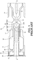
- a switching chamber 10 of a known type is shown in Figure 1 . It is a switching chamber of the "self-blast” type which is part of a gas-insulated circuit breaker.
- the switching chamber extends along a longitudinal axis XX' which globally constitutes an axis of revolution of the chamber.
- the axial and radial directions are defined with reference to the longitudinal axis XX' (the radial direction being orthogonal to the axis XX' and the axial direction being parallel to said axis).
- the switching chamber 10 comprises a pair of permanent or main contacts 12, 14 which are movable relative to one another along the axis XX'.
- contact 14 is stationary whereas contact 12 is movable along the longitudinal axis XX', under the action of an operating member (not shown).
- the switching chamber 10 also includes a pair of arcing contact 16, 18 which are also movable relative to one another along the axis XX'.
- arcing contact 16 is mechanically connected to the permanent contact 14 and is thus stationary, whereas arcing contact 16 is connected to a movable assembly 17 comprising the movable permanent contact 12.
- the switching chamber 10 is enclosed in a casing (not shown) containing an insulating gas, e.g. SF6.
- an insulating gas e.g. SF6.
- the switching chamber is operated such as to separate the permanent contacts from each other.
- the arcing contacts 16 and 18 separate shortly after that, which gives rise to an electric arc between these arcing contacts. Such arc then has to be quenched.
- the switching chamber 10 conventionally includes a main insulating nozzle 20 and an auxiliary insulating nozzle 22 which are secured to the arcing contact 18 and which contribute to delimiting an arcing region 24 where the electric arc forms when the arcing contacts 16 and 18 separate.
- a first chamber or volume referred to as the thermal volume 30 is defined inside the movable assembly 17.
- This thermal volume 30 defines a fixed volume that is brought in translation with the movable assembly 17 when the contacts separate.
- the thermal volume 30 opens out into a channel referred to as the thermal channel 32 which puts the thermal volume 30 into fluidic communication with the arcing region 24.
- Such thermal channel 32 is delimited by an outer surface 22A of the auxiliary insulating nozzle 22 and an inner surface 20A of the main insulating nozzle 20.
- the thermal channel 32 comprises a first part 32A opening in the thermal volume 30, a second part 32B opening in the arcing region 24, and a bend part 32C connecting the first part 32A to the second part 32B so as to achieve a 90 degrees turn.
- a second chamber or volume referred to as the compression volume 34 is arranged behind the thermal volume 30 and is notably delimited by a fixed back wall 36 which forms a piston or puffer which makes the volume of the compression volume 34 vary when the contacts separate.
- This back wall 36 is conventionally fitted with an over-pressure valve 37.
- the compression volume 34 communicates with the thermal volume 30 through a passageway 38 which gets closed by a valve 39 as soon as gas pressure inside the thermal volume 30 reaches a predefined level.
- the thermal energy of the arc is not sufficient to raise the gas pressure inside the thermal volume 30 at the above-mentioned predefined level, such that the valve 39 remains open. Compression of the insulating gas that will quench the arc mainly takes place in the compression volume 34 and is further increased in the thermal volume 30 by thermal energy from the arc.
- the thermal energy of the arc raises the gas pressure inside the thermal volume 30 above the predefined level, such that the valve 38 closes. Compression of the insulating gas that will quench the arc thus entirely takes place in the thermal volume 30 thanks to thermal energy from the arc.
- the bend part 32C of the thermal channel 32 is delimited by a portion of the outer surface 22A of the auxiliary insulating nozzle 22 including a first bend section B1 on the thermal volume side, a third bend section B3 on the arcing region side, and a second bend section B2 connecting the first bend section B1 to the third bend section B3.
- the first section B1 connects the second bend section B2 to a portion of the outer surface 22A delimiting the first part 32A of the thermal channel
- the third bend section B3 connects the second bend section B2 to a portion of the outer surface 22A delimiting the second part 32B of the thermal channel.
- the bend part 32C is delimited by a portion of the inner surface 20A of the main insulating nozzle 20 including a fourth bend section B4 on the thermal volume side, a sixth bend section B6 on the arcing region side, and a fifth bend section B5 connecting the fourth bend section B4 to the sixth bend section B6.
- the fourth bend section B4 connects the fifth bend section B5 to a portion of the inner surface 20A delimiting the first part 32A of the thermal channel
- the sixth bend section B6 connects the fifth bend section B5 to a portion of the inner surface 20A delimiting the second part 32B of the thermal channel.
- the first to sixth bend sections B1-B6 respectively form 30 degrees arcs of circles (see Fig. 2A : the respective angles ⁇ 1- ⁇ 6 of the first to sixth bend sections each equal 30 degrees).
- the respective radii R1, R2, R3, R4, R5 and R6 of the first to sixth bend sections B1-B6 are such that R1 > R2 > R3 and R4 > R5 > R6.
- the respective radii are decreasing from the first bend section B1 to the third bend section B3 on the one hand, and from the fourth bend section B4 to the sixth bend section B6 on the other hand.
- the respective radii R1 and R4 of the first and fourth bend sections B1 and B4 are preferably between 5 mm and 80 mm.
- the first part 32A of the thermal channel extends parallel to the axis XX' and is substantially of constant section, from the thermal volume 30 up to the bend part 32C of the thermal channel, whereas the second part 32B of the thermal channel extends orthogonal to the axis XX' and is also substantially of constant section, from the arcing region 24 up to the bend part 32C of the thermal channel.
- the radial distance D1 ( Fig. 2A ) between the outer surface 22A of the auxiliary insulating nozzle 22 and the inner surface 20A of the main insulating nozzle 20, in the first part 32A of the thermal channel, is equal to 1.35 times the radius R3 of the third bend section B3.
- the axial distance D2 between the outer surface 22A of the auxiliary insulating nozzle 22 and the inner surface 20A of the main insulating nozzle 20, in the second part 32B of the thermal channel is equal to 2.5 times the radius R3 of the third bend section B3.
- Fig. 3 shows the improvements as regards flow speed S of insulating gas in the optimized thermal channel 32 of Figs 2 and 2A (in solid line) as compared to the flow speed of insulating gas in the non-optimized thermal channel 32 of Fig 1 (in dotted line).
Landscapes
- Circuit Breakers (AREA)
Claims (12)
- Schaltkammer (10) für einen gasisolierten Schaltkreisbrecher, umfassend:zwei Lichtbogenkontakte (12, 14), die in Bezug aufeinander entlang einer Achse (XX') bewegbar sind,eine Hauptisolierdüse (20) und eine Hilfsisolierdüse (22), die sich beide um die Achse (XX') erstrecken, um einen Lichtbogenbereich (24) zu begrenzen,ein Thermalvolumen (30) zum Aufbewahren von Isoliergas,einen Thermalkanal (32), der sich zwischen einer Außenfläche (22A) der Hilfsisolierdüse (22) und einer Innenfläche (20A) der Hauptisolierdüse (20) erstreckt, sodass der Thermalkanal (32) das Thermalvolumen (30) mit dem Lichtbogenbereich (24) verbindet,wobei der Thermalkanal (32) einen ersten Teil (32A), der sich in das Thermalvolumen (30) öffnet, einen zweiten Teil (32B) im Lichtbogenbereich (24) und einen Biegeteil (32C) umfasst, der den ersten Teil (32A) mit dem zweiten Teil (32B) verbindet, um einen 90-Graddrehung zu erreichen,wobei der Biegeteil (32C) durch einen Abschnitt der Außenfläche (22A) der Hilfsisolierdüse (22) begrenzt wird, einschließlich einer ersten Biegesektion (B1) auf einer Seite des Thermalvolumens, einer dritten Biegesektion (B3) auf einer Seite des Lichtbogenbereichs und einer zweiten Biegesektion (B2), die die erste Biegesektion (B1) mit der dritten Biegesektion (B3) verbindet,dadurch gekennzeichnet, dass der Biegeteil (32C) durch einen Abschnitt der Innenfläche (20A) der Hauptisolierdüse (20) begrenzt wird, einschließlich einer vierten Biegesektion (B4) auf einer Seite des Thermalvolumens, einer sechsten Biegesektion (B6) auf einer Seite des Lichtbogenbereichs und einer fünften Biegesektion (B5), die die vierte Biegesektion (B4) mit der sechsten Biegesektion (B6) verbindet,wobei in einer axialen Querschnittsansicht die erste bis sechste Biegesektion (B1-B6) 30-Grad-Lichtbogen bilden, die entsprechende Radien R1, R2, R3, R4, R5 und R6 aufweisen,wobei R1 > R2 > R3 und R4 > R5 > R6.
- Schaltkammer nach Anspruch 1, wobei die entsprechenden Radien der ersten bis dritten Biegesektion (B1-B3) derart sind, dass R1 = 3 x R3
und
- Schaltkammer nach Anspruch 1 oder 2, wobei die entsprechenden Radien der vierten bis sechsten Biegesektion (B4-B6) derart sind, dass R4 = 3 x R6
und R5 = 1,8 x R6. - Schaltkammer nach einem der Ansprüche 1 bis 3, wobei die entsprechenden Radien der ersten bis sechsten Biegesektion (B1-B6) derart sind, dass


- Schaltkammer nach einem vorstehenden Anspruch, wobei die entsprechenden Radien R1 und R4 der ersten (B1) und vierten (B4) Biegesektion zwischen 5 mm und 80 mm betragen.
- Schaltkammer nach einem vorstehenden Anspruch, wobei der erste Teil (32A) des Thermalkanals (32) sich parallel zu der Achse (XX') von dem Thermalvolumen (30) bis zu dem Biegeteil (32C) des Thermalkanals (32) erstreckt.
- Schaltkammer nach einem vorstehenden Anspruch, wobei der zweite Teil (32B) des Thermalkanals (32) sich orthogonal zu der Achse (XX') von dem Lichtbogenbereich (24) bis zu dem Biegeteil (32C) des Thermalkanals (32) erstreckt.
- Schaltkammer nach einem vorstehenden Anspruch, wobei der erste Teil (32A) des Thermalkanals (32) von dem Thermalvolumen (30) bis zu dem Biegeteil (32C) des Thermalkanals (32) im Wesentlichen von konstantem Querschnitt ist.
- Schaltkammer nach einem vorstehenden Anspruch, wobei der zweite Teil (32B) des Thermalkanals (32) von dem Lichtbogenbereich (24) bis zu dem Biegeteil (32C) des Thermalkanals (32) im Wesentlichen von konstantem Querschnitt ist.
- Schaltkammer nach einem vorstehenden Anspruch, wobei ein radialer Abstand zwischen der Außenfläche (22A) der Hilfsisolierdüse (22) und der Innenfläche (20A) der Hauptisolierdüse (20) in dem ersten Teil (32A) des Thermalvolumens (32) das 1,35-fache des Radius R3 der dritten Biegesektion (B3) beträgt.
- Schaltkammer nach einem vorstehenden Anspruch, wobei ein axialer Abstand zwischen der Außenfläche (22A) der Hilfsisolierdüse (22) und der Innenfläche (20A) der Hauptisolierdüse (20) in dem zweiten Teil (32B) des Thermalvolumens (32) das 2,5-fache des Radius R3 der dritten Biegesektion (B3) beträgt.
- Gasisolierter Schaltkreisbrecher, umfassend eine Schaltkammer (10) nach einem der Ansprüche 1 bis 11.
Applications Claiming Priority (2)
| Application Number | Priority Date | Filing Date | Title |
|---|---|---|---|
| US15/475,424 US10026571B1 (en) | 2017-03-31 | 2017-03-31 | Switching chamber for a gas-insulated circuit breaker comprising an optimized thermal channel |
| PCT/EP2018/057063 WO2018177824A1 (en) | 2017-03-31 | 2018-03-20 | A switching chamber for a gas-insulated circuit breaker comprising an optimized thermal channel |
Publications (2)
| Publication Number | Publication Date |
|---|---|
| EP3586349A1 EP3586349A1 (de) | 2020-01-01 |
| EP3586349B1 true EP3586349B1 (de) | 2021-05-19 |
Family
ID=61750135
Family Applications (1)
| Application Number | Title | Priority Date | Filing Date |
|---|---|---|---|
| EP18712592.7A Active EP3586349B1 (de) | 2017-03-31 | 2018-03-20 | Schaltkammer für einen gasisolierten leistungsschalter mit einem optimierten wärmekanal |
Country Status (3)
| Country | Link |
|---|---|
| US (1) | US10026571B1 (de) |
| EP (1) | EP3586349B1 (de) |
| WO (1) | WO2018177824A1 (de) |
Families Citing this family (2)
| Publication number | Priority date | Publication date | Assignee | Title |
|---|---|---|---|---|
| EP3407370B1 (de) * | 2017-05-24 | 2020-04-01 | General Electric Technology GmbH | Druckgasschalter mit optimierter gasspeicherkammer |
| EP4246548A1 (de) * | 2022-03-15 | 2023-09-20 | Hitachi Energy Switzerland AG | Unterbrechereinheit für eine gasisolierte hoch- oder mittelspannungsvorrichtung und gasisolierte hoch- oder mittelspannungsvorrichtung |
Family Cites Families (13)
| Publication number | Priority date | Publication date | Assignee | Title |
|---|---|---|---|---|
| JPS5438572A (en) * | 1977-09-02 | 1979-03-23 | Hitachi Ltd | Buffer type gas circuit breaker |
| CH643394A5 (de) * | 1978-10-26 | 1984-05-30 | Tokyo Shibaura Electric Co | Gasschalter. |
| FR2596575B1 (fr) * | 1986-03-26 | 1988-05-20 | Alsthom | Disjoncteur a gaz dielectrique sous pression |
| FR2638564B1 (fr) * | 1988-11-02 | 1990-11-30 | Alsthom Gec | Disjoncteur a haute tension a gaz dielectrique sous pression |
| FR2647255B1 (fr) * | 1989-05-17 | 1993-04-23 | Alsthom Gec | Disjoncteur a haute tension a gaz dielectrique de soufflage |
| FR2647949B1 (fr) * | 1989-05-31 | 1994-02-18 | Gec Alsthom Sa | Disjoncteur a haute tension a gaz dielectrique de soufflage |
| FR2661550B1 (fr) * | 1990-04-26 | 1992-06-12 | Alsthom Gec | Disjoncteur a haute tension a arc serie. |
| FR2808118B1 (fr) * | 2000-04-19 | 2004-06-18 | Alstom | Interrupteur a auto-soufflage avec une chambre de coupure a deux volumes |
| EP1675144A1 (de) * | 2004-12-23 | 2006-06-28 | ABB Technology AG | Hochleistungsschalter mit abbrandfester Kurzschlusstromführung |
| FR2937179A1 (fr) * | 2008-10-09 | 2010-04-16 | Areva T & D Sa | Chambre de coupure pour disjoncteur haute tension a soufflage d'arc ameliore |
| JP5516568B2 (ja) * | 2011-12-28 | 2014-06-11 | 株式会社日立製作所 | パッファ形ガス遮断器 |
| WO2013153112A1 (en) * | 2012-04-11 | 2013-10-17 | Abb Technology Ag | Circuit breaker |
| EP2887367A1 (de) * | 2013-12-19 | 2015-06-24 | ABB Technology AB | Gasisolierter Hochspannungsschutzschalter |
-
2017
- 2017-03-31 US US15/475,424 patent/US10026571B1/en active Active
-
2018
- 2018-03-20 EP EP18712592.7A patent/EP3586349B1/de active Active
- 2018-03-20 WO PCT/EP2018/057063 patent/WO2018177824A1/en not_active Ceased
Non-Patent Citations (1)
| Title |
|---|
| None * |
Also Published As
| Publication number | Publication date |
|---|---|
| EP3586349A1 (de) | 2020-01-01 |
| WO2018177824A1 (en) | 2018-10-04 |
| US10026571B1 (en) | 2018-07-17 |
Similar Documents
| Publication | Publication Date | Title |
|---|---|---|
| JP5516568B2 (ja) | パッファ形ガス遮断器 | |
| US9741514B2 (en) | Switching arrangement | |
| JPWO2015008515A1 (ja) | ガス遮断器 | |
| KR20150003396A (ko) | 가스 차단기 | |
| US7732727B2 (en) | Heavy-duty circuit-breaker with sealing against hot gas | |
| US10026571B1 (en) | Switching chamber for a gas-insulated circuit breaker comprising an optimized thermal channel | |
| US3842226A (en) | Circuit interrupter using a double-throat nozzle | |
| US10347446B2 (en) | Gas blast switch comprising an optimized gas storage chamber | |
| KR101701817B1 (ko) | 가스절연 차단기 | |
| JP2013125720A (ja) | パッファ形ガス遮断器 | |
| US11373824B2 (en) | Gas-insulated high or medium voltage circuit breaker | |
| JPH02230625A (ja) | 中高電圧回路遮断器 | |
| EP3503152B1 (de) | Gasisolierter hoch- oder mittelspannungsleistungsschalter | |
| CN106128887B (zh) | 一种低压真空断路器以及用于断路器的真空灭弧室 | |
| EP3985703A1 (de) | Leistungsschalter mit verbessertem gasströmungsmanagement | |
| US20120261385A1 (en) | Gas circuit breaker | |
| CN104969324A (zh) | 触头布置及具有此类触头布置的电开关装置 | |
| US20100096363A1 (en) | Switching chamber for a high-voltage breaker, and a high-voltage breaker | |
| EP4141901B1 (de) | Metallgekapselter schutzschalter | |
| EP3872829B1 (de) | Gasschutzschalter | |
| EP3433869B1 (de) | Elektrische schutzschaltervorrichtung | |
| US12322935B2 (en) | Compressed gas switch | |
| JP2016143473A (ja) | ガス遮断器 | |
| EP3355332B1 (de) | Schutzschalter mit einer doppelwand um seine thermische kammer | |
| JP5422472B2 (ja) | ガス遮断器 |
Legal Events
| Date | Code | Title | Description |
|---|---|---|---|
| STAA | Information on the status of an ep patent application or granted ep patent |
Free format text: STATUS: UNKNOWN |
|
| STAA | Information on the status of an ep patent application or granted ep patent |
Free format text: STATUS: THE INTERNATIONAL PUBLICATION HAS BEEN MADE |
|
| PUAI | Public reference made under article 153(3) epc to a published international application that has entered the european phase |
Free format text: ORIGINAL CODE: 0009012 |
|
| STAA | Information on the status of an ep patent application or granted ep patent |
Free format text: STATUS: REQUEST FOR EXAMINATION WAS MADE |
|
| 17P | Request for examination filed |
Effective date: 20190924 |
|
| AK | Designated contracting states |
Kind code of ref document: A1 Designated state(s): AL AT BE BG CH CY CZ DE DK EE ES FI FR GB GR HR HU IE IS IT LI LT LU LV MC MK MT NL NO PL PT RO RS SE SI SK SM TR |
|
| AX | Request for extension of the european patent |
Extension state: BA ME |
|
| DAV | Request for validation of the european patent (deleted) | ||
| DAX | Request for extension of the european patent (deleted) | ||
| GRAP | Despatch of communication of intention to grant a patent |
Free format text: ORIGINAL CODE: EPIDOSNIGR1 |
|
| STAA | Information on the status of an ep patent application or granted ep patent |
Free format text: STATUS: GRANT OF PATENT IS INTENDED |
|
| INTG | Intention to grant announced |
Effective date: 20201211 |
|
| GRAS | Grant fee paid |
Free format text: ORIGINAL CODE: EPIDOSNIGR3 |
|
| GRAA | (expected) grant |
Free format text: ORIGINAL CODE: 0009210 |
|
| STAA | Information on the status of an ep patent application or granted ep patent |
Free format text: STATUS: THE PATENT HAS BEEN GRANTED |
|
| AK | Designated contracting states |
Kind code of ref document: B1 Designated state(s): AL AT BE BG CH CY CZ DE DK EE ES FI FR GB GR HR HU IE IS IT LI LT LU LV MC MK MT NL NO PL PT RO RS SE SI SK SM TR |
|
| REG | Reference to a national code |
Ref country code: GB Ref legal event code: FG4D |
|
| REG | Reference to a national code |
Ref country code: CH Ref legal event code: EP |
|
| REG | Reference to a national code |
Ref country code: DE Ref legal event code: R096 Ref document number: 602018017294 Country of ref document: DE |
|
| REG | Reference to a national code |
Ref country code: AT Ref legal event code: REF Ref document number: 1394798 Country of ref document: AT Kind code of ref document: T Effective date: 20210615 |
|
| REG | Reference to a national code |
Ref country code: IE Ref legal event code: FG4D |
|
| REG | Reference to a national code |
Ref country code: LT Ref legal event code: MG9D |
|
| REG | Reference to a national code |
Ref country code: AT Ref legal event code: MK05 Ref document number: 1394798 Country of ref document: AT Kind code of ref document: T Effective date: 20210519 |
|
| REG | Reference to a national code |
Ref country code: NL Ref legal event code: MP Effective date: 20210519 |
|
| PG25 | Lapsed in a contracting state [announced via postgrant information from national office to epo] |
Ref country code: AT Free format text: LAPSE BECAUSE OF FAILURE TO SUBMIT A TRANSLATION OF THE DESCRIPTION OR TO PAY THE FEE WITHIN THE PRESCRIBED TIME-LIMIT Effective date: 20210519 Ref country code: BG Free format text: LAPSE BECAUSE OF FAILURE TO SUBMIT A TRANSLATION OF THE DESCRIPTION OR TO PAY THE FEE WITHIN THE PRESCRIBED TIME-LIMIT Effective date: 20210819 Ref country code: HR Free format text: LAPSE BECAUSE OF FAILURE TO SUBMIT A TRANSLATION OF THE DESCRIPTION OR TO PAY THE FEE WITHIN THE PRESCRIBED TIME-LIMIT Effective date: 20210519 Ref country code: LT Free format text: LAPSE BECAUSE OF FAILURE TO SUBMIT A TRANSLATION OF THE DESCRIPTION OR TO PAY THE FEE WITHIN THE PRESCRIBED TIME-LIMIT Effective date: 20210519 Ref country code: FI Free format text: LAPSE BECAUSE OF FAILURE TO SUBMIT A TRANSLATION OF THE DESCRIPTION OR TO PAY THE FEE WITHIN THE PRESCRIBED TIME-LIMIT Effective date: 20210519 |
|
| PG25 | Lapsed in a contracting state [announced via postgrant information from national office to epo] |
Ref country code: PT Free format text: LAPSE BECAUSE OF FAILURE TO SUBMIT A TRANSLATION OF THE DESCRIPTION OR TO PAY THE FEE WITHIN THE PRESCRIBED TIME-LIMIT Effective date: 20210920 Ref country code: RS Free format text: LAPSE BECAUSE OF FAILURE TO SUBMIT A TRANSLATION OF THE DESCRIPTION OR TO PAY THE FEE WITHIN THE PRESCRIBED TIME-LIMIT Effective date: 20210519 Ref country code: SE Free format text: LAPSE BECAUSE OF FAILURE TO SUBMIT A TRANSLATION OF THE DESCRIPTION OR TO PAY THE FEE WITHIN THE PRESCRIBED TIME-LIMIT Effective date: 20210519 Ref country code: NO Free format text: LAPSE BECAUSE OF FAILURE TO SUBMIT A TRANSLATION OF THE DESCRIPTION OR TO PAY THE FEE WITHIN THE PRESCRIBED TIME-LIMIT Effective date: 20210819 Ref country code: PL Free format text: LAPSE BECAUSE OF FAILURE TO SUBMIT A TRANSLATION OF THE DESCRIPTION OR TO PAY THE FEE WITHIN THE PRESCRIBED TIME-LIMIT Effective date: 20210519 Ref country code: LV Free format text: LAPSE BECAUSE OF FAILURE TO SUBMIT A TRANSLATION OF THE DESCRIPTION OR TO PAY THE FEE WITHIN THE PRESCRIBED TIME-LIMIT Effective date: 20210519 Ref country code: IS Free format text: LAPSE BECAUSE OF FAILURE TO SUBMIT A TRANSLATION OF THE DESCRIPTION OR TO PAY THE FEE WITHIN THE PRESCRIBED TIME-LIMIT Effective date: 20210919 Ref country code: GR Free format text: LAPSE BECAUSE OF FAILURE TO SUBMIT A TRANSLATION OF THE DESCRIPTION OR TO PAY THE FEE WITHIN THE PRESCRIBED TIME-LIMIT Effective date: 20210820 |
|
| PG25 | Lapsed in a contracting state [announced via postgrant information from national office to epo] |
Ref country code: NL Free format text: LAPSE BECAUSE OF FAILURE TO SUBMIT A TRANSLATION OF THE DESCRIPTION OR TO PAY THE FEE WITHIN THE PRESCRIBED TIME-LIMIT Effective date: 20210519 |
|
| PG25 | Lapsed in a contracting state [announced via postgrant information from national office to epo] |
Ref country code: CZ Free format text: LAPSE BECAUSE OF FAILURE TO SUBMIT A TRANSLATION OF THE DESCRIPTION OR TO PAY THE FEE WITHIN THE PRESCRIBED TIME-LIMIT Effective date: 20210519 Ref country code: DK Free format text: LAPSE BECAUSE OF FAILURE TO SUBMIT A TRANSLATION OF THE DESCRIPTION OR TO PAY THE FEE WITHIN THE PRESCRIBED TIME-LIMIT Effective date: 20210519 Ref country code: RO Free format text: LAPSE BECAUSE OF FAILURE TO SUBMIT A TRANSLATION OF THE DESCRIPTION OR TO PAY THE FEE WITHIN THE PRESCRIBED TIME-LIMIT Effective date: 20210519 Ref country code: ES Free format text: LAPSE BECAUSE OF FAILURE TO SUBMIT A TRANSLATION OF THE DESCRIPTION OR TO PAY THE FEE WITHIN THE PRESCRIBED TIME-LIMIT Effective date: 20210519 Ref country code: EE Free format text: LAPSE BECAUSE OF FAILURE TO SUBMIT A TRANSLATION OF THE DESCRIPTION OR TO PAY THE FEE WITHIN THE PRESCRIBED TIME-LIMIT Effective date: 20210519 Ref country code: SK Free format text: LAPSE BECAUSE OF FAILURE TO SUBMIT A TRANSLATION OF THE DESCRIPTION OR TO PAY THE FEE WITHIN THE PRESCRIBED TIME-LIMIT Effective date: 20210519 Ref country code: SM Free format text: LAPSE BECAUSE OF FAILURE TO SUBMIT A TRANSLATION OF THE DESCRIPTION OR TO PAY THE FEE WITHIN THE PRESCRIBED TIME-LIMIT Effective date: 20210519 |
|
| REG | Reference to a national code |
Ref country code: DE Ref legal event code: R097 Ref document number: 602018017294 Country of ref document: DE |
|
| PLBE | No opposition filed within time limit |
Free format text: ORIGINAL CODE: 0009261 |
|
| STAA | Information on the status of an ep patent application or granted ep patent |
Free format text: STATUS: NO OPPOSITION FILED WITHIN TIME LIMIT |
|
| 26N | No opposition filed |
Effective date: 20220222 |
|
| PG25 | Lapsed in a contracting state [announced via postgrant information from national office to epo] |
Ref country code: IS Free format text: LAPSE BECAUSE OF FAILURE TO SUBMIT A TRANSLATION OF THE DESCRIPTION OR TO PAY THE FEE WITHIN THE PRESCRIBED TIME-LIMIT Effective date: 20210919 Ref country code: AL Free format text: LAPSE BECAUSE OF FAILURE TO SUBMIT A TRANSLATION OF THE DESCRIPTION OR TO PAY THE FEE WITHIN THE PRESCRIBED TIME-LIMIT Effective date: 20210519 |
|
| PG25 | Lapsed in a contracting state [announced via postgrant information from national office to epo] |
Ref country code: IT Free format text: LAPSE BECAUSE OF FAILURE TO SUBMIT A TRANSLATION OF THE DESCRIPTION OR TO PAY THE FEE WITHIN THE PRESCRIBED TIME-LIMIT Effective date: 20210519 |
|
| PG25 | Lapsed in a contracting state [announced via postgrant information from national office to epo] |
Ref country code: MC Free format text: LAPSE BECAUSE OF FAILURE TO SUBMIT A TRANSLATION OF THE DESCRIPTION OR TO PAY THE FEE WITHIN THE PRESCRIBED TIME-LIMIT Effective date: 20210519 |
|
| GBPC | Gb: european patent ceased through non-payment of renewal fee |
Effective date: 20220320 |
|
| REG | Reference to a national code |
Ref country code: BE Ref legal event code: MM Effective date: 20220331 |
|
| PG25 | Lapsed in a contracting state [announced via postgrant information from national office to epo] |
Ref country code: LU Free format text: LAPSE BECAUSE OF NON-PAYMENT OF DUE FEES Effective date: 20220320 Ref country code: IE Free format text: LAPSE BECAUSE OF NON-PAYMENT OF DUE FEES Effective date: 20220320 Ref country code: GB Free format text: LAPSE BECAUSE OF NON-PAYMENT OF DUE FEES Effective date: 20220320 |
|
| PG25 | Lapsed in a contracting state [announced via postgrant information from national office to epo] |
Ref country code: BE Free format text: LAPSE BECAUSE OF NON-PAYMENT OF DUE FEES Effective date: 20220331 |
|
| P01 | Opt-out of the competence of the unified patent court (upc) registered |
Effective date: 20230522 |
|
| PG25 | Lapsed in a contracting state [announced via postgrant information from national office to epo] |
Ref country code: MK Free format text: LAPSE BECAUSE OF FAILURE TO SUBMIT A TRANSLATION OF THE DESCRIPTION OR TO PAY THE FEE WITHIN THE PRESCRIBED TIME-LIMIT Effective date: 20210519 Ref country code: CY Free format text: LAPSE BECAUSE OF FAILURE TO SUBMIT A TRANSLATION OF THE DESCRIPTION OR TO PAY THE FEE WITHIN THE PRESCRIBED TIME-LIMIT Effective date: 20210519 |
|
| PG25 | Lapsed in a contracting state [announced via postgrant information from national office to epo] |
Ref country code: HU Free format text: LAPSE BECAUSE OF FAILURE TO SUBMIT A TRANSLATION OF THE DESCRIPTION OR TO PAY THE FEE WITHIN THE PRESCRIBED TIME-LIMIT; INVALID AB INITIO Effective date: 20180320 |
|
| PG25 | Lapsed in a contracting state [announced via postgrant information from national office to epo] |
Ref country code: MT Free format text: LAPSE BECAUSE OF FAILURE TO SUBMIT A TRANSLATION OF THE DESCRIPTION OR TO PAY THE FEE WITHIN THE PRESCRIBED TIME-LIMIT Effective date: 20210519 |
|
| PGFP | Annual fee paid to national office [announced via postgrant information from national office to epo] |
Ref country code: CH Payment date: 20250401 Year of fee payment: 8 |
|
| PG25 | Lapsed in a contracting state [announced via postgrant information from national office to epo] |
Ref country code: TR Free format text: LAPSE BECAUSE OF FAILURE TO SUBMIT A TRANSLATION OF THE DESCRIPTION OR TO PAY THE FEE WITHIN THE PRESCRIBED TIME-LIMIT Effective date: 20210519 |
|
| REG | Reference to a national code |
Ref country code: CH Ref legal event code: U11 Free format text: ST27 STATUS EVENT CODE: U-0-0-U10-U11 (AS PROVIDED BY THE NATIONAL OFFICE) Effective date: 20260401 |
|
| PGFP | Annual fee paid to national office [announced via postgrant information from national office to epo] |
Ref country code: DE Payment date: 20260219 Year of fee payment: 9 |
|
| PGFP | Annual fee paid to national office [announced via postgrant information from national office to epo] |
Ref country code: FR Payment date: 20260219 Year of fee payment: 9 |