EP3585629B1 - Load carrying device - Google Patents
Load carrying device Download PDFInfo
- Publication number
- EP3585629B1 EP3585629B1 EP18706848.1A EP18706848A EP3585629B1 EP 3585629 B1 EP3585629 B1 EP 3585629B1 EP 18706848 A EP18706848 A EP 18706848A EP 3585629 B1 EP3585629 B1 EP 3585629B1
- Authority
- EP
- European Patent Office
- Prior art keywords
- roller
- load carrying
- valve
- carrying device
- opening
- Prior art date
- Legal status (The legal status is an assumption and is not a legal conclusion. Google has not performed a legal analysis and makes no representation as to the accuracy of the status listed.)
- Not-in-force
Links
Images



Classifications
-
- B—PERFORMING OPERATIONS; TRANSPORTING
- B60—VEHICLES IN GENERAL
- B60B—VEHICLE WHEELS; CASTORS; AXLES FOR WHEELS OR CASTORS; INCREASING WHEEL ADHESION
- B60B19/00—Wheels not otherwise provided for or having characteristics specified in one of the subgroups of this group
- B60B19/14—Ball-type wheels
-
- B—PERFORMING OPERATIONS; TRANSPORTING
- B60—VEHICLES IN GENERAL
- B60B—VEHICLE WHEELS; CASTORS; AXLES FOR WHEELS OR CASTORS; INCREASING WHEEL ADHESION
- B60B33/00—Castors in general ; Anti-clogging castors
- B60B33/0036—Castors in general ; Anti-clogging castors characterised by type of wheels
- B60B33/0044—Roller type wheels, i.e. extra wide wheels
-
- B—PERFORMING OPERATIONS; TRANSPORTING
- B60—VEHICLES IN GENERAL
- B60B—VEHICLE WHEELS; CASTORS; AXLES FOR WHEELS OR CASTORS; INCREASING WHEEL ADHESION
- B60B33/00—Castors in general ; Anti-clogging castors
- B60B33/006—Castors in general ; Anti-clogging castors characterised by details of the swivel mechanism
- B60B33/0063—Castors in general ; Anti-clogging castors characterised by details of the swivel mechanism no swivelling action, i.e. no real caster
-
- B—PERFORMING OPERATIONS; TRANSPORTING
- B60—VEHICLES IN GENERAL
- B60C—VEHICLE TYRES; TYRE INFLATION; TYRE CHANGING; CONNECTING VALVES TO INFLATABLE ELASTIC BODIES IN GENERAL; DEVICES OR ARRANGEMENTS RELATED TO TYRES
- B60C23/00—Devices for measuring, signalling, controlling, or distributing tyre pressure or temperature, specially adapted for mounting on vehicles; Arrangement of tyre inflating devices on vehicles, e.g. of pumps or of tanks; Tyre cooling arrangements
- B60C23/001—Devices for manually or automatically controlling or distributing tyre pressure whilst the vehicle is moving
-
- B—PERFORMING OPERATIONS; TRANSPORTING
- B60—VEHICLES IN GENERAL
- B60C—VEHICLE TYRES; TYRE INFLATION; TYRE CHANGING; CONNECTING VALVES TO INFLATABLE ELASTIC BODIES IN GENERAL; DEVICES OR ARRANGEMENTS RELATED TO TYRES
- B60C23/00—Devices for measuring, signalling, controlling, or distributing tyre pressure or temperature, specially adapted for mounting on vehicles; Arrangement of tyre inflating devices on vehicles, e.g. of pumps or of tanks; Tyre cooling arrangements
- B60C23/10—Arrangement of tyre-inflating pumps mounted on vehicles
-
- B—PERFORMING OPERATIONS; TRANSPORTING
- B60—VEHICLES IN GENERAL
- B60K—ARRANGEMENT OR MOUNTING OF PROPULSION UNITS OR OF TRANSMISSIONS IN VEHICLES; ARRANGEMENT OR MOUNTING OF PLURAL DIVERSE PRIME-MOVERS IN VEHICLES; AUXILIARY DRIVES FOR VEHICLES; INSTRUMENTATION OR DASHBOARDS FOR VEHICLES; ARRANGEMENTS IN CONNECTION WITH COOLING, AIR INTAKE, GAS EXHAUST OR FUEL SUPPLY OF PROPULSION UNITS IN VEHICLES
- B60K7/00—Disposition of motor in, or adjacent to, traction wheel
- B60K7/0007—Disposition of motor in, or adjacent to, traction wheel the motor being electric
-
- B—PERFORMING OPERATIONS; TRANSPORTING
- B60—VEHICLES IN GENERAL
- B60B—VEHICLE WHEELS; CASTORS; AXLES FOR WHEELS OR CASTORS; INCREASING WHEEL ADHESION
- B60B33/00—Castors in general ; Anti-clogging castors
- B60B33/0028—Construction of wheels; methods of assembling on axle
-
- B—PERFORMING OPERATIONS; TRANSPORTING
- B60—VEHICLES IN GENERAL
- B60C—VEHICLE TYRES; TYRE INFLATION; TYRE CHANGING; CONNECTING VALVES TO INFLATABLE ELASTIC BODIES IN GENERAL; DEVICES OR ARRANGEMENTS RELATED TO TYRES
- B60C23/00—Devices for measuring, signalling, controlling, or distributing tyre pressure or temperature, specially adapted for mounting on vehicles; Arrangement of tyre inflating devices on vehicles, e.g. of pumps or of tanks; Tyre cooling arrangements
- B60C23/001—Devices for manually or automatically controlling or distributing tyre pressure whilst the vehicle is moving
- B60C23/004—Devices for manually or automatically controlling or distributing tyre pressure whilst the vehicle is moving the control being done on the wheel, e.g. using a wheel-mounted reservoir
-
- B—PERFORMING OPERATIONS; TRANSPORTING
- B60—VEHICLES IN GENERAL
- B60K—ARRANGEMENT OR MOUNTING OF PROPULSION UNITS OR OF TRANSMISSIONS IN VEHICLES; ARRANGEMENT OR MOUNTING OF PLURAL DIVERSE PRIME-MOVERS IN VEHICLES; AUXILIARY DRIVES FOR VEHICLES; INSTRUMENTATION OR DASHBOARDS FOR VEHICLES; ARRANGEMENTS IN CONNECTION WITH COOLING, AIR INTAKE, GAS EXHAUST OR FUEL SUPPLY OF PROPULSION UNITS IN VEHICLES
- B60K7/00—Disposition of motor in, or adjacent to, traction wheel
- B60K2007/0092—Disposition of motor in, or adjacent to, traction wheel the motor axle being coaxial to the wheel axle
-
- B—PERFORMING OPERATIONS; TRANSPORTING
- B62—LAND VEHICLES FOR TRAVELLING OTHERWISE THAN ON RAILS
- B62B—HAND-PROPELLED VEHICLES, e.g. HAND CARTS OR PERAMBULATORS; SLEDGES
- B62B2301/00—Wheel arrangements; Steering; Stability; Wheel suspension
- B62B2301/25—Wheel arrangements; Steering; Stability; Wheel suspension characterised by the ground engaging elements, e.g. wheel type
- B62B2301/252—Wheel arrangements; Steering; Stability; Wheel suspension characterised by the ground engaging elements, e.g. wheel type by using ball-shaped wheels
Definitions
- the invention relates to a load carrying device and a roller for a load carrying device.
- Load carrying devices typically include wheels to support the load carrying device and to allow movement of the device by rotation of the wheels. Wheels can be bulky, which means that they take up a lot of space when storing or transporting a load carrying device. Additionally, the ride provided to the load carrying device by wheels can be firm, and it can be difficult to manoeuvre load carrying devices having wheels on some terrain (such as steps, stairs, kerbs, sand, grass and onto/off public transport).
- DE10247700 discloses a tire pressure adjustment system for pumping up or reducing the pressure in the tires of a wheeled vehicle, especially a bicycle, comprises a pressure generation or reduction device incorporated in the wheel hub;
- US3827369 discloses a wheelbarrow having a spherical wheel.
- the load carrying device is advantageous as it means that when the load carrying device is not being used for load carrying, the inflation arrangement can be operated to deflate the roller to its deflated state, so that the load carrying device takes up less space during storage or transportation of the load carrying device. Additionally, the inflated roller offers increased shock absorption. Having the inflation arrangement in connection with the roller means that the inflation arrangement can be operated to selectively inflate/deflate the roller without needing to connect/disconnect the inflation arrangement to/from the roller in between using the load carrying device and storing the loading carrying device.
- the connection between the inflation arrangement and the roller is fluid communication between the inflation arrangement and the body of the roller.
- the connection between the inflation arrangement and the roller may be an electrical or mechanical connection.
- the electrical connection may be a wireless connection.
- the roller is a ball.
- the ball provides a softer ride for the load carrying device. Additionally, the ball means that the load carrying device can be pushed more easily over uneven terrain such as steps, stairs, kerbs, sand, grass and onto/off public transport. Additionally, the ball reduces damage to surfaces such as fine turf.
- the attachment arrangement comprises at least one connector connecting to an axle of the roller.
- the axle provides a simple to manufacture arrangement for attaching the roller to the load carrying portion while allowing the roller to rotate.
- the inflation arrangement provides the axle. This reduces the space required within the roller for the inflation arrangement/axle, allowing a greater inflation volume to be provided, thereby providing a softer ride, and makes the inflation arrangement/axle to occupy a smaller footprint, which reduces the weight and likelihood of damage of the load carrying device.
- the inflation arrangement extends across a width of the roller. This provides greater stability and allows the inflation arrangement to be fixed in position with respect to the roller more easily.
- the inflation arrangement is at least partially located within the roller. This reduces space occupied by the inflation arrangement in the load carrying device and reduces the likelihood of interference of the inflation arrangement with the load carrying portion. Having some of the inflation arrangement located outside the roller allows it to be accessed more easily by the user. In one example, the inflation arrangement is fully located within the roller. This further reduces space occupied by the inflation arrangement in the load carrying device and reduces the likelihood of interfere of the inflation arrangement with the load carrying portion.
- the inflation arrangement comprises a first guard member on a first end cap of the inflation arrangement, the first guard member extending outwardly from the inflation arrangement to protect the inflation arrangement from radial or sideways impact.
- the inflation arrangement comprises a second guard member on a second end cap of the inflation arrangement, the second guard member extending outwardly from the inflation arrangement to protect the inflation arrangement from radial or sideways impact.
- the inflation arrangement is a module removable from the roller. This means that if one of the roller or the inflation arrangement is damaged or broken, it can be easily replaced or repaired independently from the other.
- the body of the roller comprises a first port, the inflation arrangement insertable into and removable from the roller through the first port.
- This provides a simple and easy to manufacture means by which the inflation arrangement is removable from the roller.
- the first port also provides access to the inflation arrangement.
- the body of the roller comprises a second port, wherein the first end cap is located at the first port and the second end cap is located at the second port.
- the second port provides further access to the inflation arrangement.
- the second cap has a larger diameter than the second port and a smaller diameter than the first port. This means that the inflation arrangement is insertable into and removable from the roller through the first port (by inserting the second cap through the first port), but the inflation arrangement cannot be moved out of the roller through the second port (as the second cap cannot pass through the second port), thereby helping to retain the inflation arrangement within the roller.
- the first cap has a larger diameter than the first port. This prevents the first cap being inserted through the first port, thereby helping the inflation arrangement to be inserted in the correct position in the roller.
- the inflation arrangement comprises a pump. This is a simple and rapid means for inflating and/or deflating the roller.
- the inflation arrangement comprises first and second valves, the pump switchable between: an inflating mode, wherein the pump supplies air to the body through the first and second valves to inflate the roller; and a deflating mode, wherein the pump draws air from the body through the second and first valves to deflate the roller.
- the first and second valves are shuttle valves, the first valve comprising: a first valve first opening, opening external to the roller; a first valve second opening, opening to a suction side of the pump; and a first valve third opening, opening to the body, wherein the second valve comprises: a second valve first opening, opening external to the roller; a second valve second opening, opening to a pressure side of the pump; and a second valve third opening, opening to the body, wherein in the inflating mode, the first valve permits fluid between the first valve first opening and the first valve second opening and the second valve permits fluid flow between the second valve second opening and the second valve third opening, and, in the deflating mode, the first valve permits fluid flow between the first valve third opening and the first valve second opening and the second valve permits fluid flow between the second valve second opening and the second valve first opening.
- the pump can be driven in one direction and remain in the same position, but can inflate and deflate the roller by switching the pump. Additionally, the pump is located within a chamber of the inflation arrangement. This simplifies the construction of the inflation arrangement.
- first valve and the second valve are operable by mechanical linkage. In one example, the first valve and the second valve are operable by (e.g. remote) electrical, mechanical, or electromechanical actuation. This allows the first valve and the second valve to be operated remotely (e.g. from a handle of the load carrying device).
- each of the first valve and the second valve is located in a respective one of a first end cap and a second end cap of the inflation arrangement. This allows the valves to be positioned close to the surface of the roller so that they may more easily draw/supply air to/from the outside, and/or be accessed by a user or control devices.
- the roller comprises a plurality of structural members.
- each of the structural member extends circumferentially around the roller when the roller is inflated. This provides further structural support to the roller when the roller is in the inflated state and/or guides inflation/deflation of the ball.
- each of the structural members extends parallel to the inflation arrangement when the roller is in the deflated state.
- the pump is driven by a first motor and operation of the first motor is controlled by a pressure sensor.
- the load carrying device comprises a second motor operable to rotate the roller to move the load carrying device. This means that the load carrying device can be driven, reducing the effort required by the user of the load carrying device.
- the load carrying device comprises a third motor operable to rotate the roller to move the load carrying device, wherein the second motor is located at the first end cap and the third motor is located at the second end cap. This provides more even driving of the roller and more balanced loading on the roller.
- the body of the roller is made from a puncture resistant material.
- the load carrying device is a pram/buggy, for carrying young children.
- the roller means that the pram can be pushed more easily over uneven terrain such as steps, stairs, kerbs, sand, grass and onto/off public transport.
- the pram/buggy is advantageous as it means that when the pram/buggy is not being used for load carrying, the inflation arrangement can be operated to deflate the roller to its deflated state, so that the pram/buggy takes up less space during storage or transportation of the pram/buggy, for example in a car boot. Additionally, the inflated roller offers increased shock absorption.
- the load carrying device is a golf trolley/buggy, for carrying golf clubs.
- the roller means that the golf trolley can be pushed more easily over uneven terrain and reduces damage to surfaces such as fine turf on a golf course.
- the golf trolley/buggy is advantageous as it means that when the golf trolley/buggy is not being used for load carrying, the inflation arrangement can be operated to deflate the roller to its deflated state, so that the golf trolley/buggy takes up less space during storage or transportation of the golf trolley/buggy, for example in a car boot. Additionally, the inflated roller offers increased shock absorption.
- kit of parts for a load carrying device as defined in the claims that follow.
- the parts of the kit of parts can be assembled to give a load carrying device having the features and advantages described above.
- a roller for a load carrying device as defined in the claims that follow.
- the roller is advantageous when used with a load carrying device as it means that when the load carrying device is not being used for load carrying, the inflation arrangement can be operated to deflate the roller to its deflated state, so that the load carrying device takes up less space during storage or transportation of the load carrying device.
- the inflation arrangement is in (e.g. permanent) connection with the roller for selectively inflating the roller from a deflated state to an inflated state and for selectively deflating the roller from the inflated state to the deflated state.
- the connection might be such that free rotation of the roller is possible.
- the roller is a ball.
- the ball provides a softer ride for the load carrying device. Additionally, when used with the load carrying device, the ball allows the load carrying device to be pushed more easily over uneven terrain such as steps, stairs, kerbs, sand, grass and onto/off public transport. Additionally, the ball reduces damage to surfaces such as fine turf.
- the attachment arrangement comprises at least one connector connecting to an axle of the roller.
- the axle provides a simple to manufacture arrangement for attaching the roller to the load carrying portion while allowing the roller to rotate.
- the inflation arrangement provides the axle. This reduces the space required within the roller for the inflation arrangement/axle, allowing a greater inflation volume to be provided, thereby providing a softer ride and makes the inflation arrangement/axle occupy a smaller footprint, which reduces the weight and likelihood of damage of the load carrying device.
- the inflation arrangement is at least partially located within the roller. When the roller is attached to the load carrying device, this reduces space occupied by the inflation arrangement in the load carrying device and reduces the likelihood of interference of the inflation arrangement with the load carrying portion. Having some of the inflation arrangement located outside the roller allows it to be accessed more easily by the user. In one example, the inflation arrangement is fully located within the roller. This further reduces space occupied by the inflation arrangement in the load carrying device and reduces the likelihood of interfere of the inflation arrangement with the load carrying portion.
- the inflation arrangement comprises a first guard member on the first end cap of the inflation arrangement, the first guard member extending outwardly from the inflation arrangement to protect the inflation arrangement from radial or sideways impact.
- the inflation arrangement comprises a second guard member on the second end cap of the inflation arrangement, the second guard member extending outwardly from the inflation arrangement to protect the inflation arrangement from radial or sideways impact.
- the inflation arrangement is a module removable from the roller. This means that if one of the roller or the inflation arrangement is damaged or broken, it can be easily replaced or repaired independently from the other.
- the body of the roller comprises a first port, the inflation arrangement insertable into and removable from the roller through the first port.
- This provides a simple and easy to manufacture means by which the inflation arrangement is removable from the roller.
- the first port also provides access to the inflation arrangement.
- the body of the roller comprises a second port, wherein the first end cap is located at the first port and the second end cap is located at the second port.
- the second port provides further access to the inflation arrangement.
- the second cap has a larger diameter than the second port and a smaller diameter than the first port. This means that the inflation arrangement is insertable into and removable from the roller through the first port (by inserting the second cap through the first port), but the inflation arrangement cannot be moved out of the roller through the second port (as the second cap cannot pass through the second port), thereby helping to retain the inflation arrangement within the roller.
- the first cap has a larger diameter than the first port. This prevents the first cap being inserted through the first port, thereby helping the inflation arrangement to be inserted in its correct position in the roller.
- the inflation arrangement comprises a pump. This is a simple and rapid means for inflating and/or deflating the roller.
- the inflation arrangement comprises first and second valves, the pump switchable between: an inflating mode, wherein the pump supplies air to the body through the first and second valves to inflate the roller; and a deflating mode, wherein the pump draws air from the body through the second and first valves to deflate the roller.
- first and second valves in this way provides a reliable and simple means by which the roller can be inflated and can be readily retained in the deflated state.
- the first and second valves are shuttle valves, the first valve comprising: a first valve first opening, opening external to the roller; a first valve second opening, opening to a suction side of the pump; and a first valve third opening, opening to the body, wherein the second valve comprises: a second valve first opening, opening external to the roller; a second valve second opening, opening to a pressure side of the pump; and a second valve third opening, opening to the body, wherein in the inflating mode, the first valve permits fluid between the first valve first opening and the first valve second opening and the second valve permits fluid flow between the second valve second opening and the second valve third opening, and, in the deflating mode, the first valve permits fluid flow between the first valve third opening and the first valve second opening and the second valve permits fluid flow between the second valve second opening and the second valve first opening.
- the pump can be driven in one direction and remain in the same position, but can inflate and deflate the roller by switching the pump. Additionally, the pump is located within a chamber of the inflation arrangement. This simplifies the construction of the inflation arrangement.
- first valve and the second valve are operable by mechanical linkage. In one example, the first valve and the second valve are operable by (e.g. remote) electrical, mechanical, or electromechanical actuation. This allows the first valve and the second valve to be operated remotely (e.g. from a handle of the load carrying device).
- the inflation arrangement extends across a width of the roller. This provides greater stability and allows the inflation arrangement to be fixed in position with respect to the roller more easily.
- each of the first valve and the second valve is located in a respective one of a first end cap and a second end cap of the inflation arrangement. This allows the valves to be positioned close to the surface of the roller so that they may more easily draw/supply air to/from the outside, and/or be accessed by a user or control devices.
- the roller comprises a plurality of structural members.
- each of the structural member extends circumferentially around the roller when the roller is in the inflated state. This provides further structural support to the roller when the roller is in the inflated state, and/or guides inflation/deflation of the ball.
- each of the structural members extends parallel to the inflation arrangement when the ball is in the deflated state.
- the pump is driven by a first motor and operation of the first motor is controlled by a pressure sensor.
- the roller comprises a second motor operable to rotate the roller to move the load carrying device. This means that the load carrying device can be driven, reducing the effort required by the user of the load carrying device.
- the roller comprises comprising a third motor operable to rotate the roller to move the load carrying device, wherein the second motor is located on the first side of the roller and the third motor is located on the second side of the roller. This provides more even driving of the roller and more balanced loading on the roller.
- a pram comprising a load carrying portion and a roller as defined in the claims that follow.
- the fourth aspect of the invention may be employed in combination with any of the features of the first to third aspects as described above.
- a golf trolley comprising a load carrying portion and a roller as defined in the claims that follow.
- the fifth aspect of the invention may be employed in combination with any of the features of the first to third aspects as described above.
- Fig. 1 there is shown a portion of a load carrying device 100.
- the load carrying device 100 comprises a load carrying portion, which comprises a frame 102.
- the load carrying device 100 is described in full below with respect to Fig. 7a and Fig. 7b .
- the load carrying device 100 comprises a roller 104.
- the roller 104 comprises an attachment arrangement 106a 106b, which attaches the roller 104 to the load carrying portion, for example one or more bearings or rotatable joints.
- the attachment arrangement might also facilitate electrical connection to components with the roller 104, either directly or via apertures/conduits for wires etc.
- the roller comprises a body 108 and an inflation arrangement 110.
- the roller 104 is rotatable.
- the inflation arrangement 110 is of substantially cuboidal shape.
- the inflation arrangement 110 provides an axle for the load carrying device 100 and roller 104.
- the inflation arrangement 110 extends across a width of the roller 104.
- the inflation arrangement 110 extends across a diameter of the roller 104.
- the body 108 of the roller 104 rotates relative to the inflation unit 110.
- the arrangement 106a 106b comprises a first connector 106a and a second connector 106b.
- the first connector 106a engages a first end of the inflation arrangement 110 while the second connector 106 engages a second end of the inflation arrangement 110, to thereby attach the inflation arrangement 104 to the load carrying portion.
- Each of the first connector 106a and the second connector 106b comprises a slip ring to provide a connection affording relative rotation between the body 108 and the inflation unit 110.
- the inflation arrangement 110 comprises a first end cap 112 at the first end of the inflation arrangement 110.
- the inflation arrangement 110 comprises a second end cap 114 at the second end of the inflation arrangement 110.
- the first end cap 112 and second end cap 114 are formed of components separate from a central portion of the inflation arrangement 110. However, it will be appreciated that in other examples, the first end cap 112 and second end cap 114 are integrally formed with the central portion of the inflation arrangement 110.
- the first end cap 112 comprises a first guard member 116.
- the second end cap 114 comprises a second guard member 118.
- the first and second guard members 116 118 extend outwardly (radially and perpendicular to an axis of rotation of the roller 104) from the inflation arrangement 110.
- Each of the first and second guard members 116, 118 is of a substantially spherical dome shape.
- the roller 104 is a ball, as its body 108 is substantially ball shaped.
- the body 108 is substantially spherical.
- the body 108 has a curvature in a direction parallel to the axle which is similar to its curvature in directions normal to the axle.
- the roller 104 is in an inflated state, such that its hollow body 108 is full of air.
- the body 108 is constructed from a puncture resistant material.
- the body 108 is constructed from woven nylon reinforced fabric symmetrically coated with uncured polychloroprene rubber.
- the roller 104 comprises a plurality of structural members (not shown). Each of the structural members extends circumferentially around the roller 104 when the roller 104 is in the inflated state.
- the roller 104 provides support to the load carrying portion, in order to support a load carried by the load carrying portion. It will be appreciated that further support (in addition to the roller 104) is provided to the load carrying portion, as described below with respect to Fig. 7a and Fig. 7b . Therefore, the roller 104 partially supports the load carrying portion. The roller 104 is rotated to move the load carrying device 100.
- the inflation arrangement 110 and the axle are substantially horizontal and parallel to a surface which supports the roller 104 (e.g. a floor or surface on which the roller is to roll).
- the inflation arrangement 110 rotates with the roller 104. Relative rotation occurs between the connectors 106a 106b and the inflation arrangement 110.
- the inflation arrangement 110 is operated to deflate the roller 104 from the inflated state to a deflated state.
- the inflation arrangement 110 is operated to inflate the roller 104 from the deflated state to the inflated state.
- the operation of the inflation arrangement 110 to deflate and inflate the roller 104 is described below with respect to Fig. 4 and Fig. 5 .
- the roller 104 comprises a first port 117 and a second port 119.
- the first port 117 and the second port 119 are located on opposite sides of the body 108.
- Each of the first port 117 and the second port 119 is substantially circular.
- a centre point of the first port 117 is diametrically opposite a centre point of the second port 119 on the body 108.
- the second port 119 has a diameter which is smaller than a diameter of the first port 117.
- the inflation arrangement 110 is inserted into the roller 104 through the first port 117, as described with reference to Fig. 3 .
- the inflation arrangement 110 is removed from the roller 104 through the first port 117, as described with reference to Fig. 3 .
- the roller 104 comprises a first port 117 and a second port 119.
- the second end cap 114 has a diameter (measured in a direction perpendicular to the axle) which is larger than the second port 119.
- the second end cap 114 has a diameter which is smaller than the first port 117. It is the second guard member 118 which provides the diameter of the second end cap 114, as the second guard member 118 is the part of the second end cap 114 which extends furthest outwardly from the inflation arrangement 110.
- the first end cap 112 has a diameter which is larger than the diameter than the second end cap 114.
- the first end cap 112 has a diameter which is larger than the first port 117. It is the first guard member 116 which provides the diameter of the first end cap 112, as the first guard member 117 is the part of the first end cap 112 which extends furthest outwardly from the inflation arrangement 110.
- the inflation arrangement 110 is removed from the roller 104 through the first port 117, as the second end cap 114 passes through the first port 117.
- the inflation arrangement 110 is inserted into the roller 104 by inserting the second end cap 114 through the first port 117.
- the inflation arrangement 110 is inserted until the second end cap 114 abuts the body 108 at the second port 119 and the first end cap 116 abuts the body 108 at the first port 117 (as shown in Fig. 1 ).
- the first connector 106a is brought into engagement with the first end cap 112 and the second connector 106b is brought into engagement with the second end cap 114.
- the first connector 106a and the second connector 106b are connected to the frame 102 to attach the roller 104 to the load carrying portion.
- the inflation arrangement 110 comprises a pump 120 located in a chamber 130 of the inflation arrangement 110.
- the inflation arrangement 110 comprises a motor (not shown) to drive the pump 120.
- the inflation arrangement 110 is connected to a battery (not shown) to power the motor.
- the battery is located outside the roller 104 on the frame 102 of the load carrying device 100.
- the battery is a 24V rechargeable battery.
- the inflation arrangement 110 comprises a first valve 122 and a second valve 124.
- the first valve 122 is a shuttle valve.
- the second valve 124 is a shuttle valve.
- the first valve comprises a first valve first opening 125, which is an opening external to the roller 104.
- the first valve first opening 125 is located at one of the first end cap 112 and the second end cap 114. In the example of Fig. 4 and Fig. 5 , the first valve first opening 125 is located in the second end cap 114.
- the first valve 122 comprises a first valve second opening 126, which is an opening to a suction side 132 of the chamber 130.
- the first valve 122 comprises a first valve third opening 127, which is an opening to the body 108 of the roller.
- the second valve 124 comprises a second valve first opening 128, which is an opening external to the roller 104.
- the second valve first opening 128 is located at one of the first end cap 112 and the second end cap 114. In the example of Fig. 4 and Fig. 5 , the second valve first opening 128 is located in the first end cap 112. It will be appreciated that in other examples, the chamber 130 of the inflation arrangement 110 is inverted with respect to the rest of the inflation arrangement 110, so that the first valve first opening 125 is located at the second end cap 114 and the second valve first opening 128 is located at the first end cap 112.
- the second valve 124 comprises a second valve second opening 129, which is an opening to a pressure side 134 of the chamber 134.
- the second valve 124 comprises a second valve third opening 131, which is an opening to the body 108.
- a shuttle of the first valve 122 and a shuttle of the second valve 124 are in outward positions. This means that the first valve first opening 125 is closed and the second valve first opening 128 is closed. This prevents air flow into and out of the roller 108.
- the pump 120 is switched into an inflating mode (as shown in Fig. 4 ), by pushing the shuttle of the first valve 122 into an inward position and maintaining the shuttle of the second valve 124 in the outward position.
- the pump 120 is switched into the inflating mode using a switch located on a handle of the load carrying device 100.
- the switch may communicate wirelessly with the pump 120 and valves 122 124 to switch to the inflating mode.
- Pushing the shuttle of the first valve 122 into the inward position opens the first valve first opening 125 and the first valve second opening 126, and closes the first valve third opening 127. Maintaining the shuttle of the second valve 124 in the outward position maintains the second valve second opening 129 and the second valve third opening 131 open and the second valve first opening 128 closed.
- the motor drives the pump 120, which draws air from outside through the first valve first opening 125, into the suction side 132 of the chamber 130 through the first valve second opening 126.
- the pump 120 supplies air to the pressure side 134, thereby supplying air to the body 108 through the second valve second opening 129 and the second valve third opening 131.
- the inflating mode is automated, such that the inflating mode continues until the body 108 is fully inflated, at which point a pressure sensor (not shown) of the inflation unit 110 senses that the body 108 is fully inflated, the motor switches off and the shuttle of the first valve 122 is returned to the outward position, thereby maintaining the roller 104 in an inflated state.
- the roller 104 is used to support the load carrying device 100.
- the pump 120 is switched into a deflating mode (as shown in Fig. 5 ), by pushing the shuttle of the second valve 124 into an inward position and maintaining the shuttle of the first valve 122 in the outward position.
- the pump 120 is switched into the deflating mode using a switch (not shown) located on a handle of the load carrying device 100.
- the switch may communicate wirelessly with the pump 120 and valves 122 124 to switch to the deflating mode.
- Pushing the shuttle of the second valve 124 into the inward position opens the second valve first opening 128 and the second valve second opening 129, and closes the second valve third opening 131. Maintaining the shuttle of the first valve 122 in the outward position maintains the first valve second opening 126 and the first valve third opening 127 open and the first valve first opening 125 closed.
- the motor drives the pump 120, which draws air from body 108 through the first valve third opening 127 and the first valve second opening 126, into the suction side 132 of the chamber 130.
- the pump 120 supplies air to the pressure side 134 thereby supplying air to the outside through the second valve second opening 129 and the second valve first opening 128.
- the deflating mode is automated, such that the deflating mode continues until the body 108 is fully deflated, at which point the pressure sensor senses that the body 108 is fully deflated, the motor switches off, and the shuttle of the second valve 124 is returned to the outward position, thereby maintaining the roller 104 in a deflated state.
- the first valve 122 is closed to the body 108 and is open to the outside.
- the second valve 124 is closed to the outside and is open to the body 108.
- the pump 120 draws air from the outside through the first valve 122 into the suction side 132 of the chamber.
- the pump 120 supplies air into the pressure side 134. Air flows from the pressure side 134 through the second valve 124 into the body 108.
- the first valve 122 is closed to the outside and is open to the body 108.
- the second valve 124 is closed to the body 108 and is open to the outside.
- the pump 120 draws air from the body 108, through the first valve 122 and the suction side 132 of the chamber.
- the pump 120 supplies air to the pressure side 134 of the chamber. Air flows from the pressure side 134 through the second valve 124 to the outside.
- the inflation and deflation may not require a sensor. Inflation and deflation can be undertaken manually, until a required state of inflation or deflation is achieved.
- Pushing the shuttle of the first valve 122 may be achieved by pulling a cable (e.g. located on a handle of the load carrying device) in a first direction to activate a first microswitch to push the shuttle of the first valve 122.
- Pushing the shuttle of the second valve 124 is achieved by pulling a cable in a second direction to activate a second microswitch to push the shuttle of the second valve 124. Pulling the cable in either direction activates the pump.
- inflation/deflation occurs while the cable is pulled and until the cable is released.
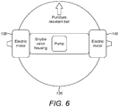
- FIG. 6 there is shown a schematic drawing of a cross-section of a second roller 136.
- the second roller 136 comprises all of the features of the roller 104. Additionally, the second roller 136 comprises a second motor 138 and a third motor 140.
- the second motor 138 is located outside the second roller 136 adjacent to the first end cap 112.
- the third motor 140 is located outside the second roller 136 adjacent to the second end cap 114.
- the second motor 138 and the third motor 140 rotate the second roller 136, thereby moving a load carrying device to which the second roller 136 is attached.
- the load carrying device 100 is a pram.
- the pram comprises a load carrying portion 101, which comprises the frame 102.
- the load carrying portion 101 comprises a child carrying portion.
- the pram comprises the roller 104 as described above.
- the roller 104 is located at the front of the pram.
- the pram comprises a pair of wheels located at the rear of the pram.
- the pram comprises a handle 152.
- the pram is supported by the roller 104 and the pair of wheels 150.
- the roller 104 can be deflated as described above and the pram folded when storing or transporting the pram.
- the inflation arrangement drives inflation and deflation using the pump. This is advantageous as inflation and deflation takes place quickly and can be controlled easily.
- the inflation arrangement may comprise a compressible foam (or other biasing means) which inflates the roller when a valve is open, and may be compressed (e.g. manually) by a user to deflate the roller when the valve is open.
- the valve can be closed to maintain the roller in an inflated or deflated state.
- the inflation arrangement may comprise a foldable structure for expanding and compressing the body 108, for example in the manner in which a typical umbrella/umbrella frame operates.
- the body 108 need not be sealed, and the inflation is achieved by the folding of the structure rather than the pressure within the body 108. That is, in this latter example, inflation and deflation refer to expansion and compression of the overall size or shape of the body, and do not necessarily involve or required the use or air or similar.
- the expansion and compression can be purely or largely mechanical.
Landscapes
- Engineering & Computer Science (AREA)
- Mechanical Engineering (AREA)
- Chemical & Material Sciences (AREA)
- Combustion & Propulsion (AREA)
- Transportation (AREA)
- Handcart (AREA)
- Rollers For Roller Conveyors For Transfer (AREA)
Description
- The invention relates to a load carrying device and a roller for a load carrying device.
- Load carrying devices (such as prams and golf trolleys) typically include wheels to support the load carrying device and to allow movement of the device by rotation of the wheels. Wheels can be bulky, which means that they take up a lot of space when storing or transporting a load carrying device. Additionally, the ride provided to the load carrying device by wheels can be firm, and it can be difficult to manoeuvre load carrying devices having wheels on some terrain (such as steps, stairs, kerbs, sand, grass and onto/off public transport).
- Background art is shown, for example, in:
DE10247700 , which discloses a tire pressure adjustment system for pumping up or reducing the pressure in the tires of a wheeled vehicle, especially a bicycle, comprises a pressure generation or reduction device incorporated in the wheel hub; andUS3827369 , which discloses a wheelbarrow having a spherical wheel. - According to a first aspect of the invention, there is provided a load carrying device as defined in the claims that follow.
- The load carrying device is advantageous as it means that when the load carrying device is not being used for load carrying, the inflation arrangement can be operated to deflate the roller to its deflated state, so that the load carrying device takes up less space during storage or transportation of the load carrying device. Additionally, the inflated roller offers increased shock absorption. Having the inflation arrangement in connection with the roller means that the inflation arrangement can be operated to selectively inflate/deflate the roller without needing to connect/disconnect the inflation arrangement to/from the roller in between using the load carrying device and storing the loading carrying device. Typically, the connection between the inflation arrangement and the roller is fluid communication between the inflation arrangement and the body of the roller. However, the connection between the inflation arrangement and the roller may be an electrical or mechanical connection. The electrical connection may be a wireless connection.
- In the invention as claimed, the roller is a ball. The ball provides a softer ride for the load carrying device. Additionally, the ball means that the load carrying device can be pushed more easily over uneven terrain such as steps, stairs, kerbs, sand, grass and onto/off public transport. Additionally, the ball reduces damage to surfaces such as fine turf.
- In one example, the attachment arrangement comprises at least one connector connecting to an axle of the roller. The axle provides a simple to manufacture arrangement for attaching the roller to the load carrying portion while allowing the roller to rotate.
- In the invention as claimed, the inflation arrangement provides the axle. This reduces the space required within the roller for the inflation arrangement/axle, allowing a greater inflation volume to be provided, thereby providing a softer ride, and makes the inflation arrangement/axle to occupy a smaller footprint, which reduces the weight and likelihood of damage of the load carrying device.
- In one example, the inflation arrangement extends across a width of the roller. This provides greater stability and allows the inflation arrangement to be fixed in position with respect to the roller more easily.
- In the invention as claimed, the inflation arrangement is at least partially located within the roller. This reduces space occupied by the inflation arrangement in the load carrying device and reduces the likelihood of interference of the inflation arrangement with the load carrying portion. Having some of the inflation arrangement located outside the roller allows it to be accessed more easily by the user. In one example, the inflation arrangement is fully located within the roller. This further reduces space occupied by the inflation arrangement in the load carrying device and reduces the likelihood of interfere of the inflation arrangement with the load carrying portion.
- In one example, the inflation arrangement comprises a first guard member on a first end cap of the inflation arrangement, the first guard member extending outwardly from the inflation arrangement to protect the inflation arrangement from radial or sideways impact.
- In one example, the inflation arrangement comprises a second guard member on a second end cap of the inflation arrangement, the second guard member extending outwardly from the inflation arrangement to protect the inflation arrangement from radial or sideways impact.
- In one example, the inflation arrangement is a module removable from the roller. This means that if one of the roller or the inflation arrangement is damaged or broken, it can be easily replaced or repaired independently from the other.
- In one example, the body of the roller comprises a first port, the inflation arrangement insertable into and removable from the roller through the first port. This provides a simple and easy to manufacture means by which the inflation arrangement is removable from the roller. The first port also provides access to the inflation arrangement.
- In one example, the body of the roller comprises a second port, wherein the first end cap is located at the first port and the second end cap is located at the second port. The second port provides further access to the inflation arrangement.
- In one example, the second cap has a larger diameter than the second port and a smaller diameter than the first port. This means that the inflation arrangement is insertable into and removable from the roller through the first port (by inserting the second cap through the first port), but the inflation arrangement cannot be moved out of the roller through the second port (as the second cap cannot pass through the second port), thereby helping to retain the inflation arrangement within the roller.
- In one example, the first cap has a larger diameter than the first port. This prevents the first cap being inserted through the first port, thereby helping the inflation arrangement to be inserted in the correct position in the roller.
- In one example, the inflation arrangement comprises a pump. This is a simple and rapid means for inflating and/or deflating the roller.
- In one example, the inflation arrangement comprises first and second valves, the pump switchable between: an inflating mode, wherein the pump supplies air to the body through the first and second valves to inflate the roller; and a deflating mode, wherein the pump draws air from the body through the second and first valves to deflate the roller. Using first and second valvles in this way provides a reliable and simple means by which the roller can be inflated and can be readily retained in the deflated state.
- In one example, the first and second valves are shuttle valves, the first valve comprising: a first valve first opening, opening external to the roller; a first valve second opening, opening to a suction side of the pump; and a first valve third opening, opening to the body, wherein the second valve comprises: a second valve first opening, opening external to the roller; a second valve second opening, opening to a pressure side of the pump; and a second valve third opening, opening to the body, wherein in the inflating mode, the first valve permits fluid between the first valve first opening and the first valve second opening and the second valve permits fluid flow between the second valve second opening and the second valve third opening, and, in the deflating mode, the first valve permits fluid flow between the first valve third opening and the first valve second opening and the second valve permits fluid flow between the second valve second opening and the second valve first opening.
- Using this arrangement of the two valves means that the pump can be driven in one direction and remain in the same position, but can inflate and deflate the roller by switching the pump. Additionally, the pump is located within a chamber of the inflation arrangement. This simplifies the construction of the inflation arrangement.
- In one example, the first valve and the second valve are operable by mechanical linkage. In one example, the first valve and the second valve are operable by (e.g. remote) electrical, mechanical, or electromechanical actuation. This allows the first valve and the second valve to be operated remotely (e.g. from a handle of the load carrying device).
- In one example, each of the first valve and the second valve is located in a respective one of a first end cap and a second end cap of the inflation arrangement. This allows the valves to be positioned close to the surface of the roller so that they may more easily draw/supply air to/from the outside, and/or be accessed by a user or control devices.
- In one example, the roller comprises a plurality of structural members. In one example, each of the structural member extends circumferentially around the roller when the roller is inflated. This provides further structural support to the roller when the roller is in the inflated state and/or guides inflation/deflation of the ball.
- In one example, each of the structural members extends parallel to the inflation arrangement when the roller is in the deflated state.
- In one example, wherein the pump is driven by a first motor and operation of the first motor is controlled by a pressure sensor.
- In one example, the load carrying device comprises a second motor operable to rotate the roller to move the load carrying device. This means that the load carrying device can be driven, reducing the effort required by the user of the load carrying device.
- In one example, the load carrying device comprises a third motor operable to rotate the roller to move the load carrying device, wherein the second motor is located at the first end cap and the third motor is located at the second end cap. This provides more even driving of the roller and more balanced loading on the roller.
- In one example, the body of the roller is made from a puncture resistant material.
- In one example, the load carrying device is a pram/buggy, for carrying young children. The roller means that the pram can be pushed more easily over uneven terrain such as steps, stairs, kerbs, sand, grass and onto/off public transport. The pram/buggy is advantageous as it means that when the pram/buggy is not being used for load carrying, the inflation arrangement can be operated to deflate the roller to its deflated state, so that the pram/buggy takes up less space during storage or transportation of the pram/buggy, for example in a car boot. Additionally, the inflated roller offers increased shock absorption.
- In one example, the load carrying device is a golf trolley/buggy, for carrying golf clubs. The roller means that the golf trolley can be pushed more easily over uneven terrain and reduces damage to surfaces such as fine turf on a golf course. The golf trolley/buggy is advantageous as it means that when the golf trolley/buggy is not being used for load carrying, the inflation arrangement can be operated to deflate the roller to its deflated state, so that the golf trolley/buggy takes up less space during storage or transportation of the golf trolley/buggy, for example in a car boot. Additionally, the inflated roller offers increased shock absorption.
- According to a second aspect of the invention, there is provided a kit of parts for a load carrying device, as defined in the claims that follow. The parts of the kit of parts can be assembled to give a load carrying device having the features and advantages described above.
- According to a third aspect of the invention, there is provided a roller for a load carrying device, as defined in the claims that follow.
- The roller is advantageous when used with a load carrying device as it means that when the load carrying device is not being used for load carrying, the inflation arrangement can be operated to deflate the roller to its deflated state, so that the load carrying device takes up less space during storage or transportation of the load carrying device. In one example, the inflation arrangement is in (e.g. permanent) connection with the roller for selectively inflating the roller from a deflated state to an inflated state and for selectively deflating the roller from the inflated state to the deflated state. The connection might be such that free rotation of the roller is possible.
- In the invention as claimed, the roller is a ball. The ball provides a softer ride for the load carrying device. Additionally, when used with the load carrying device, the ball allows the load carrying device to be pushed more easily over uneven terrain such as steps, stairs, kerbs, sand, grass and onto/off public transport. Additionally, the ball reduces damage to surfaces such as fine turf.
- In one example, the attachment arrangement comprises at least one connector connecting to an axle of the roller. The axle provides a simple to manufacture arrangement for attaching the roller to the load carrying portion while allowing the roller to rotate.
- In the invention as claimed, the inflation arrangement provides the axle. This reduces the space required within the roller for the inflation arrangement/axle, allowing a greater inflation volume to be provided, thereby providing a softer ride and makes the inflation arrangement/axle occupy a smaller footprint, which reduces the weight and likelihood of damage of the load carrying device.
- In the invention as claimed, the inflation arrangement is at least partially located within the roller. When the roller is attached to the load carrying device, this reduces space occupied by the inflation arrangement in the load carrying device and reduces the likelihood of interference of the inflation arrangement with the load carrying portion. Having some of the inflation arrangement located outside the roller allows it to be accessed more easily by the user. In one example, the inflation arrangement is fully located within the roller. This further reduces space occupied by the inflation arrangement in the load carrying device and reduces the likelihood of interfere of the inflation arrangement with the load carrying portion.
- In one example, the inflation arrangement comprises a first guard member on the first end cap of the inflation arrangement, the first guard member extending outwardly from the inflation arrangement to protect the inflation arrangement from radial or sideways impact.
- In one example, the inflation arrangement comprises a second guard member on the second end cap of the inflation arrangement, the second guard member extending outwardly from the inflation arrangement to protect the inflation arrangement from radial or sideways impact.
- In one example, the inflation arrangement is a module removable from the roller. This means that if one of the roller or the inflation arrangement is damaged or broken, it can be easily replaced or repaired independently from the other.
- In one example, the body of the roller comprises a first port, the inflation arrangement insertable into and removable from the roller through the first port. This provides a simple and easy to manufacture means by which the inflation arrangement is removable from the roller. The first port also provides access to the inflation arrangement.
- In one example, the body of the roller comprises a second port, wherein the first end cap is located at the first port and the second end cap is located at the second port. The second port provides further access to the inflation arrangement.
- In one example, the second cap has a larger diameter than the second port and a smaller diameter than the first port. This means that the inflation arrangement is insertable into and removable from the roller through the first port (by inserting the second cap through the first port), but the inflation arrangement cannot be moved out of the roller through the second port (as the second cap cannot pass through the second port), thereby helping to retain the inflation arrangement within the roller.
- In one example, the first cap has a larger diameter than the first port. This prevents the first cap being inserted through the first port, thereby helping the inflation arrangement to be inserted in its correct position in the roller.
- In one example, the inflation arrangement comprises a pump. This is a simple and rapid means for inflating and/or deflating the roller.
- In one example, the inflation arrangement comprises first and second valves, the pump switchable between: an inflating mode, wherein the pump supplies air to the body through the first and second valves to inflate the roller; and a deflating mode, wherein the pump draws air from the body through the second and first valves to deflate the roller. Using first and second valves in this way provides a reliable and simple means by which the roller can be inflated and can be readily retained in the deflated state.
- In one example, the first and second valves are shuttle valves, the first valve comprising: a first valve first opening, opening external to the roller; a first valve second opening, opening to a suction side of the pump; and a first valve third opening, opening to the body, wherein the second valve comprises: a second valve first opening, opening external to the roller; a second valve second opening, opening to a pressure side of the pump; and a second valve third opening, opening to the body, wherein in the inflating mode, the first valve permits fluid between the first valve first opening and the first valve second opening and the second valve permits fluid flow between the second valve second opening and the second valve third opening, and, in the deflating mode, the first valve permits fluid flow between the first valve third opening and the first valve second opening and the second valve permits fluid flow between the second valve second opening and the second valve first opening. Using this arrangement of the two valves means that the pump can be driven in one direction and remain in the same position, but can inflate and deflate the roller by switching the pump. Additionally, the pump is located within a chamber of the inflation arrangement. This simplifies the construction of the inflation arrangement.
- In one example, the first valve and the second valve are operable by mechanical linkage. In one example, the first valve and the second valve are operable by (e.g. remote) electrical, mechanical, or electromechanical actuation. This allows the first valve and the second valve to be operated remotely (e.g. from a handle of the load carrying device).
- In one example, the inflation arrangement extends across a width of the roller. This provides greater stability and allows the inflation arrangement to be fixed in position with respect to the roller more easily.
- In one example, each of the first valve and the second valve is located in a respective one of a first end cap and a second end cap of the inflation arrangement. This allows the valves to be positioned close to the surface of the roller so that they may more easily draw/supply air to/from the outside, and/or be accessed by a user or control devices.
- In one example, the roller comprises a plurality of structural members. In one example, each of the structural member extends circumferentially around the roller when the roller is in the inflated state. This provides further structural support to the roller when the roller is in the inflated state, and/or guides inflation/deflation of the ball.
- In one example, each of the structural members extends parallel to the inflation arrangement when the ball is in the deflated state.
- In one example, the pump is driven by a first motor and operation of the first motor is controlled by a pressure sensor.
- In one example, the roller comprises a second motor operable to rotate the roller to move the load carrying device. This means that the load carrying device can be driven, reducing the effort required by the user of the load carrying device.
- In one example, the roller comprises comprising a third motor operable to rotate the roller to move the load carrying device, wherein the second motor is located on the first side of the roller and the third motor is located on the second side of the roller. This provides more even driving of the roller and more balanced loading on the roller.
- According to a fourth aspect of the invention, there is provided a pram comprising a load carrying portion and a roller as defined in the claims that follow. The fourth aspect of the invention may be employed in combination with any of the features of the first to third aspects as described above.
- According to a fifth aspect of the invention, there is provided a golf trolley comprising a load carrying portion and a roller as defined in the claims that follow. The fifth aspect of the invention may be employed in combination with any of the features of the first to third aspects as described above.
- For a better understanding of the invention reference is made, by way of example only, to the accompanying drawings, in which:
-
Fig. 1 is a perspective view of a portion of a load carrying device according to an example; -
Fig. 2 is a perspective view of a portion of a roller according to an example; -
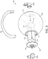
Fig. 3 is an exploded view of a portion of a load carrying device according to an example; -
Fig. 4 is a schematic drawing of a cross-section of a roller according to an example; -
Fig. 5 is a schematic drawing of a cross-section of a roller according to an example; -
Fig. 6 is a schematic drawing of a cross-section of a roller according to an example; -
Fig. 7a is a side view of a pram according to an example; and -
Fig. 7b is a front view of a pram according to an example. - Referring to
Fig. 1 there is shown a portion of aload carrying device 100. Theload carrying device 100 comprises a load carrying portion, which comprises aframe 102. Theload carrying device 100 is described in full below with respect toFig. 7a and Fig. 7b . - The
load carrying device 100 comprises aroller 104. Theroller 104 comprises anattachment arrangement 106aroller 104 to the load carrying portion, for example one or more bearings or rotatable joints. The attachment arrangement might also facilitate electrical connection to components with theroller 104, either directly or via apertures/conduits for wires etc. The roller comprises abody 108 and aninflation arrangement 110. Theroller 104 is rotatable. - The
inflation arrangement 110 is of substantially cuboidal shape. Theinflation arrangement 110 provides an axle for theload carrying device 100 androller 104. Theinflation arrangement 110 extends across a width of theroller 104. Theinflation arrangement 110 extends across a diameter of theroller 104. Thebody 108 of theroller 104 rotates relative to theinflation unit 110. Thearrangement 106a 106b comprises afirst connector 106a and asecond connector 106b. Thefirst connector 106a engages a first end of theinflation arrangement 110 while the second connector 106 engages a second end of theinflation arrangement 110, to thereby attach theinflation arrangement 104 to the load carrying portion. Each of thefirst connector 106a and thesecond connector 106b comprises a slip ring to provide a connection affording relative rotation between thebody 108 and theinflation unit 110. - The
inflation arrangement 110 comprises afirst end cap 112 at the first end of theinflation arrangement 110. Theinflation arrangement 110 comprises asecond end cap 114 at the second end of theinflation arrangement 110. Thefirst end cap 112 andsecond end cap 114 are formed of components separate from a central portion of theinflation arrangement 110. However, it will be appreciated that in other examples, thefirst end cap 112 andsecond end cap 114 are integrally formed with the central portion of theinflation arrangement 110. - The
first end cap 112 comprises afirst guard member 116. Thesecond end cap 114 comprises asecond guard member 118. The first andsecond guard members 116 118 extend outwardly (radially and perpendicular to an axis of rotation of the roller 104) from theinflation arrangement 110. Each of the first andsecond guard members - The
roller 104 is a ball, as itsbody 108 is substantially ball shaped. Thebody 108 is substantially spherical. Thebody 108 has a curvature in a direction parallel to the axle which is similar to its curvature in directions normal to the axle. InFig. 1 , theroller 104 is in an inflated state, such that itshollow body 108 is full of air. Thebody 108 is constructed from a puncture resistant material. Thebody 108 is constructed from woven nylon reinforced fabric symmetrically coated with uncured polychloroprene rubber. - The
roller 104 comprises a plurality of structural members (not shown). Each of the structural members extends circumferentially around theroller 104 when theroller 104 is in the inflated state. - In use, the
roller 104 provides support to the load carrying portion, in order to support a load carried by the load carrying portion. It will be appreciated that further support (in addition to the roller 104) is provided to the load carrying portion, as described below with respect toFig. 7a and Fig. 7b . Therefore, theroller 104 partially supports the load carrying portion. Theroller 104 is rotated to move theload carrying device 100. - The
inflation arrangement 110 and the axle are substantially horizontal and parallel to a surface which supports the roller 104 (e.g. a floor or surface on which the roller is to roll). Theinflation arrangement 110 rotates with theroller 104. Relative rotation occurs between theconnectors 106a 106b and theinflation arrangement 110. - The
inflation arrangement 110 is operated to deflate theroller 104 from the inflated state to a deflated state. Theinflation arrangement 110 is operated to inflate theroller 104 from the deflated state to the inflated state. The operation of theinflation arrangement 110 to deflate and inflate theroller 104 is described below with respect toFig. 4 and Fig. 5 . - Referring to
Fig. 2 , there is shown thebody 108 of theroller 104. Theroller 104 comprises afirst port 117 and asecond port 119. Thefirst port 117 and thesecond port 119 are located on opposite sides of thebody 108. Each of thefirst port 117 and thesecond port 119 is substantially circular. A centre point of thefirst port 117 is diametrically opposite a centre point of thesecond port 119 on thebody 108. Thesecond port 119 has a diameter which is smaller than a diameter of thefirst port 117. - In use, the
inflation arrangement 110 is inserted into theroller 104 through thefirst port 117, as described with reference toFig. 3 . Theinflation arrangement 110 is removed from theroller 104 through thefirst port 117, as described with reference toFig. 3 . - Referring to
Fig. 3 , there is shown an exploded view of the portion of theload carrying device 100 ofFig. 1 . As described above, theroller 104 comprises afirst port 117 and asecond port 119. Thesecond end cap 114 has a diameter (measured in a direction perpendicular to the axle) which is larger than thesecond port 119. Thesecond end cap 114 has a diameter which is smaller than thefirst port 117. It is thesecond guard member 118 which provides the diameter of thesecond end cap 114, as thesecond guard member 118 is the part of thesecond end cap 114 which extends furthest outwardly from theinflation arrangement 110. - The
first end cap 112 has a diameter which is larger than the diameter than thesecond end cap 114. Thefirst end cap 112 has a diameter which is larger than thefirst port 117. It is thefirst guard member 116 which provides the diameter of thefirst end cap 112, as thefirst guard member 117 is the part of thefirst end cap 112 which extends furthest outwardly from theinflation arrangement 110. - In use, as shown in
Fig. 3 , theinflation arrangement 110 is removed from theroller 104 through thefirst port 117, as thesecond end cap 114 passes through thefirst port 117. - The
inflation arrangement 110 is inserted into theroller 104 by inserting thesecond end cap 114 through thefirst port 117. Theinflation arrangement 110 is inserted until thesecond end cap 114 abuts thebody 108 at thesecond port 119 and thefirst end cap 116 abuts thebody 108 at the first port 117 (as shown inFig. 1 ). Thefirst connector 106a is brought into engagement with thefirst end cap 112 and thesecond connector 106b is brought into engagement with thesecond end cap 114. Thefirst connector 106a and thesecond connector 106b are connected to theframe 102 to attach theroller 104 to the load carrying portion. - Referring to
Fig. 4 and Fig. 5 there are shown schematic drawings of cross-sections of theroller 104. Theinflation arrangement 110 comprises apump 120 located in achamber 130 of theinflation arrangement 110. Theinflation arrangement 110 comprises a motor (not shown) to drive thepump 120. Theinflation arrangement 110 is connected to a battery (not shown) to power the motor. The battery is located outside theroller 104 on theframe 102 of theload carrying device 100. The battery is a 24V rechargeable battery. - The
inflation arrangement 110 comprises afirst valve 122 and asecond valve 124. Thefirst valve 122 is a shuttle valve. Thesecond valve 124 is a shuttle valve. The first valve comprises a first valve first opening 125, which is an opening external to theroller 104. The first valve first opening 125 is located at one of thefirst end cap 112 and thesecond end cap 114. In the example ofFig. 4 and Fig. 5 , the first valve first opening 125 is located in thesecond end cap 114. - The
first valve 122 comprises a first valvesecond opening 126, which is an opening to asuction side 132 of thechamber 130. Thefirst valve 122 comprises a first valvethird opening 127, which is an opening to thebody 108 of the roller. - The
second valve 124 comprises a second valve first opening 128, which is an opening external to theroller 104. The second valve first opening 128 is located at one of thefirst end cap 112 and thesecond end cap 114. In the example ofFig. 4 and Fig. 5 , the second valve first opening 128 is located in thefirst end cap 112. It will be appreciated that in other examples, thechamber 130 of theinflation arrangement 110 is inverted with respect to the rest of theinflation arrangement 110, so that the first valve first opening 125 is located at thesecond end cap 114 and the second valve first opening 128 is located at thefirst end cap 112. - The
second valve 124 comprises a second valvesecond opening 129, which is an opening to apressure side 134 of thechamber 134. Thesecond valve 124 comprises a second valvethird opening 131, which is an opening to thebody 108. - In use, when the
load carrying device 100 is being stored/transported and theroller 104 is in a deflated state (not shown), a shuttle of thefirst valve 122 and a shuttle of thesecond valve 124 are in outward positions. This means that the first valve first opening 125 is closed and the second valve first opening 128 is closed. This prevents air flow into and out of theroller 108. - The
pump 120 is switched into an inflating mode (as shown inFig. 4 ), by pushing the shuttle of thefirst valve 122 into an inward position and maintaining the shuttle of thesecond valve 124 in the outward position. Thepump 120 is switched into the inflating mode using a switch located on a handle of theload carrying device 100. The switch may communicate wirelessly with thepump 120 andvalves 122 124 to switch to the inflating mode. - Pushing the shuttle of the
first valve 122 into the inward position opens the first valvefirst opening 125 and the first valvesecond opening 126, and closes the first valvethird opening 127. Maintaining the shuttle of thesecond valve 124 in the outward position maintains the second valvesecond opening 129 and the second valvethird opening 131 open and the second valve first opening 128 closed. - The motor drives the
pump 120, which draws air from outside through the first valve first opening 125, into thesuction side 132 of thechamber 130 through the first valvesecond opening 126. Thepump 120 supplies air to thepressure side 134, thereby supplying air to thebody 108 through the second valvesecond opening 129 and the second valvethird opening 131. The inflating mode is automated, such that the inflating mode continues until thebody 108 is fully inflated, at which point a pressure sensor (not shown) of theinflation unit 110 senses that thebody 108 is fully inflated, the motor switches off and the shuttle of thefirst valve 122 is returned to the outward position, thereby maintaining theroller 104 in an inflated state. Theroller 104 is used to support theload carrying device 100. - The
pump 120 is switched into a deflating mode (as shown inFig. 5 ), by pushing the shuttle of thesecond valve 124 into an inward position and maintaining the shuttle of thefirst valve 122 in the outward position. Thepump 120 is switched into the deflating mode using a switch (not shown) located on a handle of theload carrying device 100. The switch may communicate wirelessly with thepump 120 andvalves 122 124 to switch to the deflating mode. - Pushing the shuttle of the
second valve 124 into the inward position opens the second valve first opening 128 and the second valvesecond opening 129, and closes the second valvethird opening 131. Maintaining the shuttle of thefirst valve 122 in the outward position maintains the first valvesecond opening 126 and the first valvethird opening 127 open and the first valve first opening 125 closed. - The motor drives the
pump 120, which draws air frombody 108 through the first valvethird opening 127 and the first valvesecond opening 126, into thesuction side 132 of thechamber 130. Thepump 120 supplies air to thepressure side 134 thereby supplying air to the outside through the second valvesecond opening 129 and the second valvefirst opening 128. The deflating mode is automated, such that the deflating mode continues until thebody 108 is fully deflated, at which point the pressure sensor senses that thebody 108 is fully deflated, the motor switches off, and the shuttle of thesecond valve 124 is returned to the outward position, thereby maintaining theroller 104 in a deflated state. - In other words, in the inflating mode, the
first valve 122 is closed to thebody 108 and is open to the outside. Thesecond valve 124 is closed to the outside and is open to thebody 108. Thepump 120 draws air from the outside through thefirst valve 122 into thesuction side 132 of the chamber. Thepump 120 supplies air into thepressure side 134. Air flows from thepressure side 134 through thesecond valve 124 into thebody 108. - In the deflating mode, the
first valve 122 is closed to the outside and is open to thebody 108. Thesecond valve 124 is closed to thebody 108 and is open to the outside. Thepump 120 draws air from thebody 108, through thefirst valve 122 and thesuction side 132 of the chamber. Thepump 120 supplies air to thepressure side 134 of the chamber. Air flows from thepressure side 134 through thesecond valve 124 to the outside. - In another example, the inflation and deflation may not require a sensor. Inflation and deflation can be undertaken manually, until a required state of inflation or deflation is achieved. Pushing the shuttle of the
first valve 122 may be achieved by pulling a cable (e.g. located on a handle of the load carrying device) in a first direction to activate a first microswitch to push the shuttle of thefirst valve 122. Pushing the shuttle of thesecond valve 124 is achieved by pulling a cable in a second direction to activate a second microswitch to push the shuttle of thesecond valve 124. Pulling the cable in either direction activates the pump. In this example, inflation/deflation occurs while the cable is pulled and until the cable is released. - Referring to
Fig. 6 , there is shown a schematic drawing of a cross-section of asecond roller 136. Thesecond roller 136 comprises all of the features of theroller 104. Additionally, thesecond roller 136 comprises asecond motor 138 and athird motor 140. Thesecond motor 138 is located outside thesecond roller 136 adjacent to thefirst end cap 112. Thethird motor 140 is located outside thesecond roller 136 adjacent to thesecond end cap 114. - In use, the
second motor 138 and thethird motor 140 rotate thesecond roller 136, thereby moving a load carrying device to which thesecond roller 136 is attached. - Referring to
Fig. 7a and Fig. 7b , there is shown theload carrying device 100. Theload carrying device 100 is a pram. The pram comprises aload carrying portion 101, which comprises theframe 102. Theload carrying portion 101 comprises a child carrying portion. The pram comprises theroller 104 as described above. Theroller 104 is located at the front of the pram. The pram comprises a pair of wheels located at the rear of the pram. The pram comprises ahandle 152. - In use, the pram is supported by the
roller 104 and the pair ofwheels 150. Theroller 104 can be deflated as described above and the pram folded when storing or transporting the pram. - In the examples described above, the inflation arrangement drives inflation and deflation using the pump. This is advantageous as inflation and deflation takes place quickly and can be controlled easily. However, in other examples, outside of the scope of the claims that follow, simpler/cheaper inflation arrangements can be employed which do not use a pump. For example, the inflation arrangement may comprise a compressible foam (or other biasing means) which inflates the roller when a valve is open, and may be compressed (e.g. manually) by a user to deflate the roller when the valve is open. When using such an inflation arrangement, the valve can be closed to maintain the roller in an inflated or deflated state. Alternatively, the inflation arrangement may comprise a foldable structure for expanding and compressing the
body 108, for example in the manner in which a typical umbrella/umbrella frame operates. In this situation, thebody 108 need not be sealed, and the inflation is achieved by the folding of the structure rather than the pressure within thebody 108. That is, in this latter example, inflation and deflation refer to expansion and compression of the overall size or shape of the body, and do not necessarily involve or required the use or air or similar. The expansion and compression can be purely or largely mechanical. - Although a few preferred embodiments have been shown and described, it will be appreciated by those skilled in the art that various changes and modifications might be made without departing from the scope of the invention, as defined in the appended claims.
Claims (15)
- A load carrying device (100) comprising a load carrying portion (102), a roller (104) and an inflation arrangement (110), comprising a pump, in connection with the roller for selectively inflating the roller from a deflated state to an inflated state and for selectively deflating the roller from the inflated state to the deflated state, the roller rotatable to allow movement of the load carrying device, the roller being a ball, wherein the inflation arrangement provides the axle for the ball, the roller comprising:an attachment arrangement (106a, 106b) attaching the roller to the load carrying portion so that the roller provides support to the load carrying portion; anda body (108) for contacting a surface on which the load carrying device is located.
- A load carrying device according to claim 1, wherein the inflation arrangement comprises a first guard member (116) on a first end cap (112) of the inflation arrangement and/or a second guard member (118) on a second end cap (114) of the inflation arrangement, the first guard member and/or second guard member extending outwardly from the inflation arrangement to protect the inflation arrangement from impact.
- A load carrying device according to any preceding claim, wherein the inflation arrangement (110) is a module removable from the roller.
- A load carrying device according to claim 3, wherein the body of the roller comprises a first port (117), the inflation arrangement insertable into and removable from the roller through the first port,and, optionally,wherein the body of the roller comprises a second port (119), wherein a first end cap of the inflation arrangement is located at the first port and a second end cap of the inflation arrangement is located at the second port.
- A load carrying device according to claim 4, wherein the second end cap (114) has a larger diameter than the second port and a smaller diameter than the first port,and, optionally,wherein the first end cap has a larger diameter than the first port.
- A load carrying device according to any preceding claim, wherein the inflation arrangement comprises first and second valves (122, 124), the pump switchable between:an inflating mode, wherein the pump supplies air to the body through the first and second valves to inflate the roller; anda deflating mode, wherein the pump (120) draws air from the body through the second and first valves to deflate the roller.
- A load carrying device according to claim 6, wherein the first and second valves are shuttle valves, the first valve comprising:a first valve first opening (125), opening external to the roller;a first valve second opening (126), opening to a suction side of the pump; anda first valve third opening (127), opening to the body,wherein the second valve comprises:a second valve first opening (128), opening external to the roller;a second valve second opening (129), opening to a pressure side of the pump; anda second valve third opening (131), opening to the body,wherein in the inflating mode, the first valve (122) permits fluid flow between the first valve first opening and the first valve second opening and the second valve permits fluid flow between the second valve second opening and the second valve third opening, and,in the deflating mode, the first valve permits fluid flow between the first valve third opening and the first valve second opening and the second valve permits fluid flow between the second valve second opening and the second valve first opening.
- A load carrying device according to claim 6 or 7, wherein the first valve (122) and second valves (124) are operable by mechanical linkage.
- A load carrying device according to any of claims 6 to 8, wherein each of the first valve and the second valve is located in a respective one of a first end cap and a second end cap of the inflation arrangement.
- A load carrying device according to any preceding claim, wherein the pump (120) is driven by a first motor and operation of the first motor is controlled by a pressure sensor,and/or, optionally,the load carrying device comprises a second motor operable to rotate the roller to move the load carrying device,and/or, optionally,the load carrying device comprises a third motor operable to rotate the roller to move the load carrying device, wherein the second motor is located at a first end cap of the inflation arrangement and the third motor is located at a second end cap of the inflation arrangement.
- A load carrying device according to any preceding claim, wherein the roller comprises a plurality of structural members,and, optionally,wherein each of the structural member extends circumferentially around the roller when the roller is in the inflated state,and/or, optionally,wherein each of the structural members extends parallel to the inflation arrangement when the ball is in the deflated state.
- A load carrying device according to any preceding claim, wherein the body is made from a puncture resistant material.
- A load carrying device according to any preceding claim, wherein the load carrying device (100) is a pram or a golf trolley.
- A kit of parts for a load carrying device (100), the load carrying device comprising a load carrying portion (102) and a roller (104), the kit of parts comprising:an attachment arrangement (106a, 106b) for attaching the roller to the load carrying portion so that the roller provides support to the load carrying portion;a body (108) of the roller for contacting a surface on which the load carrying device is located; andan inflation arrangement (110), comprising a pump, in connection with the roller for selectively inflating the roller from a deflated state to an inflated state and selectively deflating the roller from the inflated state to the deflated state,wherein the roller is rotatable in use to allow movement of the load carrying device, the roller being a ball, wherein the inflation arrangement provides the axle for the ball.
- A roller (104) for a load carrying device (100), the roller comprising:an arrangement (106a, 106b) for attaching the roller to a load carrying portion of the load carrying device so that the roller provides support to the load carrying portion;a body (108) for contacting a surface on which the load carrying device is located; andan inflation arrangement (110), comprising a pump, for selectively inflating the roller from a deflated state to an inflated state and selectively deflating the roller from the inflated state to the deflated state,wherein the roller is rotatable in use to allow movement of the load carrying device, the roller being a ball, wherein the inflation arrangement provides the axle for the ball.
Priority Applications (1)
| Application Number | Priority Date | Filing Date | Title |
|---|---|---|---|
| EP21198981.9A EP3954553A1 (en) | 2017-02-21 | 2018-02-19 | Load carrying device |
Applications Claiming Priority (2)
| Application Number | Priority Date | Filing Date | Title |
|---|---|---|---|
| GB1702802.8A GB2559814B (en) | 2017-02-21 | 2017-02-21 | Load carrying device |
| PCT/GB2018/050430 WO2018154281A1 (en) | 2017-02-21 | 2018-02-19 | Load carrying device |
Related Child Applications (1)
| Application Number | Title | Priority Date | Filing Date |
|---|---|---|---|
| EP21198981.9A Division EP3954553A1 (en) | 2017-02-21 | 2018-02-19 | Load carrying device |
Publications (2)
| Publication Number | Publication Date |
|---|---|
| EP3585629A1 EP3585629A1 (en) | 2020-01-01 |
| EP3585629B1 true EP3585629B1 (en) | 2021-09-29 |
Family
ID=58486713
Family Applications (2)
| Application Number | Title | Priority Date | Filing Date |
|---|---|---|---|
| EP18706848.1A Not-in-force EP3585629B1 (en) | 2017-02-21 | 2018-02-19 | Load carrying device |
| EP21198981.9A Withdrawn EP3954553A1 (en) | 2017-02-21 | 2018-02-19 | Load carrying device |
Family Applications After (1)
| Application Number | Title | Priority Date | Filing Date |
|---|---|---|---|
| EP21198981.9A Withdrawn EP3954553A1 (en) | 2017-02-21 | 2018-02-19 | Load carrying device |
Country Status (5)
| Country | Link |
|---|---|
| US (1) | US20190375234A1 (en) |
| EP (2) | EP3585629B1 (en) |
| CN (1) | CN110325381A (en) |
| GB (1) | GB2559814B (en) |
| WO (1) | WO2018154281A1 (en) |
Families Citing this family (4)
| Publication number | Priority date | Publication date | Assignee | Title |
|---|---|---|---|---|
| GB2594718B (en) * | 2020-05-04 | 2023-12-27 | Area 52 Ltd | Pram frame |
| CN112848876A (en) * | 2021-03-17 | 2021-05-28 | 章征凯 | Posture self-holding type walking device based on spherical support |
| KR102723852B1 (en) * | 2022-09-29 | 2024-10-31 | 한국타이어앤테크놀로지 주식회사 | Wheel module and driving apparatus comprising the same |
| USD1091299S1 (en) * | 2023-11-28 | 2025-09-02 | Farid ISMAYILOV | Wheel |
Family Cites Families (21)
| Publication number | Priority date | Publication date | Assignee | Title |
|---|---|---|---|---|
| GB525912A (en) * | 1939-03-03 | 1940-09-06 | William Turner | Improvements in tyre valve pressure gauges |
| US3016967A (en) * | 1959-09-21 | 1962-01-16 | George W Rehfeld | Motorcycle with wide tread wheels |
| US3453773A (en) * | 1965-08-26 | 1969-07-08 | Kms Ind Inc | Self-driving rolling device |
| GB1286681A (en) * | 1969-04-29 | 1972-08-23 | Ernesto Octavio Moraga | Float system for amphibious vehicles |
| US3827369A (en) * | 1972-10-02 | 1974-08-06 | H Mueller | Wheelbarrow having spherical wheel |
| GB1510011A (en) * | 1975-03-05 | 1978-05-10 | Dyson Designs | Ground engaging member for movable structures |
| US4174871A (en) * | 1978-01-03 | 1979-11-20 | Ballbarrow Corporation | Material handling vehicle |
| US4225147A (en) * | 1978-01-31 | 1980-09-30 | Lowery Michael B | Vehicles |
| CN85202403U (en) * | 1985-06-13 | 1986-04-02 | 郑永如 | Automatic air charging system for travelling tyre |
| DE3637164A1 (en) * | 1986-10-31 | 1988-05-05 | Rudolf Kurt Hermann Wuttke | Ball rolling system for motor vehicles |
| US6568695B2 (en) * | 1999-02-25 | 2003-05-27 | Mark Dornan | All terrain riding assembly having braking capabilities |
| US6254113B1 (en) * | 1999-02-25 | 2001-07-03 | Mark Dornan | All terrain riding assembly |
| DE10247700A1 (en) * | 2002-10-12 | 2004-06-17 | Trapp, Günter | Tire pressure adjustment system for pumping up or reducing the pressure in the tires of a wheeled vehicle, especially a bicycle, comprises a pressure generation or reduction device incorporated in the wheel hub |
| CN2683419Y (en) * | 2003-09-26 | 2005-03-09 | 张卫 | Built-in type tyre auto-inflation pump |
| KR100869216B1 (en) * | 2006-10-26 | 2008-11-18 | 금호타이어 주식회사 | Rotary valve for regulating tire pressure |
| GB2469675A (en) * | 2009-04-23 | 2010-10-27 | Sami Ansari | A wheel ball |
| CN101920730B (en) * | 2010-08-18 | 2012-11-21 | 于雪松 | Spherical double-wheel bidirectional car |
| FR2989935B1 (en) * | 2012-04-30 | 2016-04-15 | Aldebaran Robotics | SPHERICAL WHEEL AND VEHICLE IMPLEMENTING THE WHEEL |
| FR3005932B1 (en) * | 2013-05-21 | 2015-05-01 | France Reducteurs | ELECTROMECHANICAL ASSEMBLY FOR A ROLLING MACHINE, AND A ROLLER EQUIPPED WITH SUCH AN ELECTROMECHANICAL ASSEMBLY |
| CN204506338U (en) * | 2015-03-23 | 2015-07-29 | 葛志强 | A kind of spherical wheel on hand barrow |
| CN107867359A (en) * | 2017-12-12 | 2018-04-03 | 深圳市自由侠科技有限公司 | A kind of rugby shape wheelbarrow |
-
2017
- 2017-02-21 GB GB1702802.8A patent/GB2559814B/en active Active
-
2018
- 2018-02-19 EP EP18706848.1A patent/EP3585629B1/en not_active Not-in-force
- 2018-02-19 US US16/487,210 patent/US20190375234A1/en not_active Abandoned
- 2018-02-19 EP EP21198981.9A patent/EP3954553A1/en not_active Withdrawn
- 2018-02-19 WO PCT/GB2018/050430 patent/WO2018154281A1/en not_active Ceased
- 2018-02-19 CN CN201880012991.1A patent/CN110325381A/en active Pending
Also Published As
| Publication number | Publication date |
|---|---|
| EP3585629A1 (en) | 2020-01-01 |
| EP3954553A1 (en) | 2022-02-16 |
| GB2559814B (en) | 2019-05-22 |
| CN110325381A (en) | 2019-10-11 |
| GB201702802D0 (en) | 2017-04-05 |
| WO2018154281A1 (en) | 2018-08-30 |
| GB2559814A (en) | 2018-08-22 |
| US20190375234A1 (en) | 2019-12-12 |
Similar Documents
| Publication | Publication Date | Title |
|---|---|---|
| EP3585629B1 (en) | Load carrying device | |
| US8011736B2 (en) | Collapsible wheel | |
| US8286739B2 (en) | Self-propelled beach cart | |
| US20120160576A1 (en) | Motorized beach cart | |
| US7789180B2 (en) | Inflatable article | |
| CN1662410B (en) | Folding mobile or jogging baby pushchair and goods-transporting device with rotary wheel axle | |
| CN104822539B (en) | Collapsible wheel and method of making collapsible wheel | |
| US10016666B2 (en) | Collapsible single passenger riding golf bag cart | |
| US8596389B2 (en) | Motorized beach cart | |
| KR20130129901A (en) | Golf bag and golf cart assembly | |
| US9334007B2 (en) | Bicycle including frame with inflatable segments | |
| ES2914886T3 (en) | folding wheels | |
| EP3166701A1 (en) | One-person vehicle for urban transport | |
| US20160200335A1 (en) | Wheeled cart | |
| WO2004093595A1 (en) | Trolley type contaiiner, convertible into a scooter | |
| AU760763C (en) | Low pressure tire | |
| US20220295956A1 (en) | Transport device having a rolling body | |
| US9266389B2 (en) | Wheel system for a vehicle | |
| US20160264121A1 (en) | Inflatable Vehicle Incorporating an Air Cushion | |
| ES3061486T3 (en) | Vehicle comprising a drive unit and an application that can be detachably connected thereto | |
| CN107822284A (en) | Suitcase with protection air bag | |
| CN201855545U (en) | Electric golf cart | |
| US20250304129A1 (en) | Motorized Beach Wagon Device | |
| US20060144494A1 (en) | Low pressure tire | |
| WO2004037565A1 (en) | Low pressure tire |
Legal Events
| Date | Code | Title | Description |
|---|---|---|---|
| STAA | Information on the status of an ep patent application or granted ep patent |
Free format text: STATUS: UNKNOWN |
|
| STAA | Information on the status of an ep patent application or granted ep patent |
Free format text: STATUS: THE INTERNATIONAL PUBLICATION HAS BEEN MADE |
|
| PUAI | Public reference made under article 153(3) epc to a published international application that has entered the european phase |
Free format text: ORIGINAL CODE: 0009012 |
|
| STAA | Information on the status of an ep patent application or granted ep patent |
Free format text: STATUS: REQUEST FOR EXAMINATION WAS MADE |
|
| 17P | Request for examination filed |
Effective date: 20190813 |
|
| AK | Designated contracting states |
Kind code of ref document: A1 Designated state(s): AL AT BE BG CH CY CZ DE DK EE ES FI FR GB GR HR HU IE IS IT LI LT LU LV MC MK MT NL NO PL PT RO RS SE SI SK SM TR |
|
| AX | Request for extension of the european patent |
Extension state: BA ME |
|
| DAV | Request for validation of the european patent (deleted) | ||
| DAX | Request for extension of the european patent (deleted) | ||
| REG | Reference to a national code |
Ref country code: DE Ref legal event code: R079 Ref document number: 602018024239 Country of ref document: DE Free format text: PREVIOUS MAIN CLASS: B60C0023000000 Ipc: B60B0033000000 |
|
| RIC1 | Information provided on ipc code assigned before grant |
Ipc: B60C 23/00 20060101ALI20201218BHEP Ipc: B60B 19/14 20060101ALI20201218BHEP Ipc: B60B 33/00 20060101AFI20201218BHEP Ipc: B60C 23/10 20060101ALI20201218BHEP |
|
| GRAP | Despatch of communication of intention to grant a patent |
Free format text: ORIGINAL CODE: EPIDOSNIGR1 |
|
| STAA | Information on the status of an ep patent application or granted ep patent |
Free format text: STATUS: GRANT OF PATENT IS INTENDED |
|
| INTG | Intention to grant announced |
Effective date: 20210324 |
|
| GRAS | Grant fee paid |
Free format text: ORIGINAL CODE: EPIDOSNIGR3 |
|
| GRAA | (expected) grant |
Free format text: ORIGINAL CODE: 0009210 |
|
| STAA | Information on the status of an ep patent application or granted ep patent |
Free format text: STATUS: THE PATENT HAS BEEN GRANTED |
|
| AK | Designated contracting states |
Kind code of ref document: B1 Designated state(s): AL AT BE BG CH CY CZ DE DK EE ES FI FR GB GR HR HU IE IS IT LI LT LU LV MC MK MT NL NO PL PT RO RS SE SI SK SM TR |
|
| REG | Reference to a national code |
Ref country code: GB Ref legal event code: FG4D |
|
| REG | Reference to a national code |
Ref country code: CH Ref legal event code: EP Ref country code: AT Ref legal event code: REF Ref document number: 1433891 Country of ref document: AT Kind code of ref document: T Effective date: 20211015 |
|
| REG | Reference to a national code |
Ref country code: DE Ref legal event code: R096 Ref document number: 602018024239 Country of ref document: DE |
|
| REG | Reference to a national code |
Ref country code: IE Ref legal event code: FG4D |
|
| REG | Reference to a national code |
Ref country code: LT Ref legal event code: MG9D |
|
| PG25 | Lapsed in a contracting state [announced via postgrant information from national office to epo] |
Ref country code: BG Free format text: LAPSE BECAUSE OF FAILURE TO SUBMIT A TRANSLATION OF THE DESCRIPTION OR TO PAY THE FEE WITHIN THE PRESCRIBED TIME-LIMIT Effective date: 20211229 Ref country code: LT Free format text: LAPSE BECAUSE OF FAILURE TO SUBMIT A TRANSLATION OF THE DESCRIPTION OR TO PAY THE FEE WITHIN THE PRESCRIBED TIME-LIMIT Effective date: 20210929 Ref country code: NO Free format text: LAPSE BECAUSE OF FAILURE TO SUBMIT A TRANSLATION OF THE DESCRIPTION OR TO PAY THE FEE WITHIN THE PRESCRIBED TIME-LIMIT Effective date: 20211229 Ref country code: HR Free format text: LAPSE BECAUSE OF FAILURE TO SUBMIT A TRANSLATION OF THE DESCRIPTION OR TO PAY THE FEE WITHIN THE PRESCRIBED TIME-LIMIT Effective date: 20210929 Ref country code: FI Free format text: LAPSE BECAUSE OF FAILURE TO SUBMIT A TRANSLATION OF THE DESCRIPTION OR TO PAY THE FEE WITHIN THE PRESCRIBED TIME-LIMIT Effective date: 20210929 Ref country code: SE Free format text: LAPSE BECAUSE OF FAILURE TO SUBMIT A TRANSLATION OF THE DESCRIPTION OR TO PAY THE FEE WITHIN THE PRESCRIBED TIME-LIMIT Effective date: 20210929 Ref country code: RS Free format text: LAPSE BECAUSE OF FAILURE TO SUBMIT A TRANSLATION OF THE DESCRIPTION OR TO PAY THE FEE WITHIN THE PRESCRIBED TIME-LIMIT Effective date: 20210929 |
|
| REG | Reference to a national code |
Ref country code: NL Ref legal event code: MP Effective date: 20210929 |
|
| REG | Reference to a national code |
Ref country code: AT Ref legal event code: MK05 Ref document number: 1433891 Country of ref document: AT Kind code of ref document: T Effective date: 20210929 |
|
| PG25 | Lapsed in a contracting state [announced via postgrant information from national office to epo] |
Ref country code: LV Free format text: LAPSE BECAUSE OF FAILURE TO SUBMIT A TRANSLATION OF THE DESCRIPTION OR TO PAY THE FEE WITHIN THE PRESCRIBED TIME-LIMIT Effective date: 20210929 Ref country code: GR Free format text: LAPSE BECAUSE OF FAILURE TO SUBMIT A TRANSLATION OF THE DESCRIPTION OR TO PAY THE FEE WITHIN THE PRESCRIBED TIME-LIMIT Effective date: 20211230 |
|
| PG25 | Lapsed in a contracting state [announced via postgrant information from national office to epo] |
Ref country code: AT Free format text: LAPSE BECAUSE OF FAILURE TO SUBMIT A TRANSLATION OF THE DESCRIPTION OR TO PAY THE FEE WITHIN THE PRESCRIBED TIME-LIMIT Effective date: 20210929 |
|
| PG25 | Lapsed in a contracting state [announced via postgrant information from national office to epo] |
Ref country code: IS Free format text: LAPSE BECAUSE OF FAILURE TO SUBMIT A TRANSLATION OF THE DESCRIPTION OR TO PAY THE FEE WITHIN THE PRESCRIBED TIME-LIMIT Effective date: 20220129 Ref country code: SK Free format text: LAPSE BECAUSE OF FAILURE TO SUBMIT A TRANSLATION OF THE DESCRIPTION OR TO PAY THE FEE WITHIN THE PRESCRIBED TIME-LIMIT Effective date: 20210929 Ref country code: RO Free format text: LAPSE BECAUSE OF FAILURE TO SUBMIT A TRANSLATION OF THE DESCRIPTION OR TO PAY THE FEE WITHIN THE PRESCRIBED TIME-LIMIT Effective date: 20210929 Ref country code: PT Free format text: LAPSE BECAUSE OF FAILURE TO SUBMIT A TRANSLATION OF THE DESCRIPTION OR TO PAY THE FEE WITHIN THE PRESCRIBED TIME-LIMIT Effective date: 20220131 Ref country code: PL Free format text: LAPSE BECAUSE OF FAILURE TO SUBMIT A TRANSLATION OF THE DESCRIPTION OR TO PAY THE FEE WITHIN THE PRESCRIBED TIME-LIMIT Effective date: 20210929 Ref country code: NL Free format text: LAPSE BECAUSE OF FAILURE TO SUBMIT A TRANSLATION OF THE DESCRIPTION OR TO PAY THE FEE WITHIN THE PRESCRIBED TIME-LIMIT Effective date: 20210929 Ref country code: ES Free format text: LAPSE BECAUSE OF FAILURE TO SUBMIT A TRANSLATION OF THE DESCRIPTION OR TO PAY THE FEE WITHIN THE PRESCRIBED TIME-LIMIT Effective date: 20210929 Ref country code: EE Free format text: LAPSE BECAUSE OF FAILURE TO SUBMIT A TRANSLATION OF THE DESCRIPTION OR TO PAY THE FEE WITHIN THE PRESCRIBED TIME-LIMIT Effective date: 20210929 Ref country code: CZ Free format text: LAPSE BECAUSE OF FAILURE TO SUBMIT A TRANSLATION OF THE DESCRIPTION OR TO PAY THE FEE WITHIN THE PRESCRIBED TIME-LIMIT Effective date: 20210929 Ref country code: AL Free format text: LAPSE BECAUSE OF FAILURE TO SUBMIT A TRANSLATION OF THE DESCRIPTION OR TO PAY THE FEE WITHIN THE PRESCRIBED TIME-LIMIT Effective date: 20210929 |
|
| REG | Reference to a national code |
Ref country code: DE Ref legal event code: R097 Ref document number: 602018024239 Country of ref document: DE |
|
| PG25 | Lapsed in a contracting state [announced via postgrant information from national office to epo] |
Ref country code: DK Free format text: LAPSE BECAUSE OF FAILURE TO SUBMIT A TRANSLATION OF THE DESCRIPTION OR TO PAY THE FEE WITHIN THE PRESCRIBED TIME-LIMIT Effective date: 20210929 |
|
| PGFP | Annual fee paid to national office [announced via postgrant information from national office to epo] |
Ref country code: GB Payment date: 20220526 Year of fee payment: 5 Ref country code: FR Payment date: 20220530 Year of fee payment: 5 Ref country code: DE Payment date: 20220530 Year of fee payment: 5 |
|
| PLBE | No opposition filed within time limit |
Free format text: ORIGINAL CODE: 0009261 |
|
| STAA | Information on the status of an ep patent application or granted ep patent |
Free format text: STATUS: NO OPPOSITION FILED WITHIN TIME LIMIT |
|
| 26N | No opposition filed |
Effective date: 20220630 |
|
| PG25 | Lapsed in a contracting state [announced via postgrant information from national office to epo] |
Ref country code: MC Free format text: LAPSE BECAUSE OF FAILURE TO SUBMIT A TRANSLATION OF THE DESCRIPTION OR TO PAY THE FEE WITHIN THE PRESCRIBED TIME-LIMIT Effective date: 20210929 |
|
| REG | Reference to a national code |
Ref country code: CH Ref legal event code: PL |
|
| REG | Reference to a national code |
Ref country code: BE Ref legal event code: MM Effective date: 20220228 |
|
| PG25 | Lapsed in a contracting state [announced via postgrant information from national office to epo] |
Ref country code: LU Free format text: LAPSE BECAUSE OF NON-PAYMENT OF DUE FEES Effective date: 20220219 |
|
| PG25 | Lapsed in a contracting state [announced via postgrant information from national office to epo] |
Ref country code: SI Free format text: LAPSE BECAUSE OF FAILURE TO SUBMIT A TRANSLATION OF THE DESCRIPTION OR TO PAY THE FEE WITHIN THE PRESCRIBED TIME-LIMIT Effective date: 20210929 |
|
| PG25 | Lapsed in a contracting state [announced via postgrant information from national office to epo] |
Ref country code: LI Free format text: LAPSE BECAUSE OF NON-PAYMENT OF DUE FEES Effective date: 20220228 Ref country code: IT Free format text: LAPSE BECAUSE OF FAILURE TO SUBMIT A TRANSLATION OF THE DESCRIPTION OR TO PAY THE FEE WITHIN THE PRESCRIBED TIME-LIMIT Effective date: 20210929 Ref country code: IE Free format text: LAPSE BECAUSE OF NON-PAYMENT OF DUE FEES Effective date: 20220219 Ref country code: CH Free format text: LAPSE BECAUSE OF NON-PAYMENT OF DUE FEES Effective date: 20220228 |
|
| PG25 | Lapsed in a contracting state [announced via postgrant information from national office to epo] |
Ref country code: BE Free format text: LAPSE BECAUSE OF NON-PAYMENT OF DUE FEES Effective date: 20220228 |
|
| REG | Reference to a national code |
Ref country code: DE Ref legal event code: R119 Ref document number: 602018024239 Country of ref document: DE |
|
| GBPC | Gb: european patent ceased through non-payment of renewal fee |
Effective date: 20230219 |
|
| PG25 | Lapsed in a contracting state [announced via postgrant information from national office to epo] |
Ref country code: GB Free format text: LAPSE BECAUSE OF NON-PAYMENT OF DUE FEES Effective date: 20230219 |
|
| PG25 | Lapsed in a contracting state [announced via postgrant information from national office to epo] |
Ref country code: GB Free format text: LAPSE BECAUSE OF NON-PAYMENT OF DUE FEES Effective date: 20230219 Ref country code: FR Free format text: LAPSE BECAUSE OF NON-PAYMENT OF DUE FEES Effective date: 20230228 Ref country code: DE Free format text: LAPSE BECAUSE OF NON-PAYMENT OF DUE FEES Effective date: 20230901 |
|
| PG25 | Lapsed in a contracting state [announced via postgrant information from national office to epo] |
Ref country code: SM Free format text: LAPSE BECAUSE OF FAILURE TO SUBMIT A TRANSLATION OF THE DESCRIPTION OR TO PAY THE FEE WITHIN THE PRESCRIBED TIME-LIMIT Effective date: 20210929 Ref country code: MK Free format text: LAPSE BECAUSE OF FAILURE TO SUBMIT A TRANSLATION OF THE DESCRIPTION OR TO PAY THE FEE WITHIN THE PRESCRIBED TIME-LIMIT Effective date: 20210929 Ref country code: CY Free format text: LAPSE BECAUSE OF FAILURE TO SUBMIT A TRANSLATION OF THE DESCRIPTION OR TO PAY THE FEE WITHIN THE PRESCRIBED TIME-LIMIT Effective date: 20210929 |
|
| PG25 | Lapsed in a contracting state [announced via postgrant information from national office to epo] |
Ref country code: HU Free format text: LAPSE BECAUSE OF FAILURE TO SUBMIT A TRANSLATION OF THE DESCRIPTION OR TO PAY THE FEE WITHIN THE PRESCRIBED TIME-LIMIT; INVALID AB INITIO Effective date: 20180219 |
|
| PG25 | Lapsed in a contracting state [announced via postgrant information from national office to epo] |
Ref country code: MT Free format text: LAPSE BECAUSE OF FAILURE TO SUBMIT A TRANSLATION OF THE DESCRIPTION OR TO PAY THE FEE WITHIN THE PRESCRIBED TIME-LIMIT Effective date: 20210929 |
|
| PG25 | Lapsed in a contracting state [announced via postgrant information from national office to epo] |
Ref country code: TR Free format text: LAPSE BECAUSE OF FAILURE TO SUBMIT A TRANSLATION OF THE DESCRIPTION OR TO PAY THE FEE WITHIN THE PRESCRIBED TIME-LIMIT Effective date: 20210929 |