EP3585345B1 - Vehicle integrated storage power management system - Google Patents
Vehicle integrated storage power management system Download PDFInfo
- Publication number
- EP3585345B1 EP3585345B1 EP18757627.7A EP18757627A EP3585345B1 EP 3585345 B1 EP3585345 B1 EP 3585345B1 EP 18757627 A EP18757627 A EP 18757627A EP 3585345 B1 EP3585345 B1 EP 3585345B1
- Authority
- EP
- European Patent Office
- Prior art keywords
- light
- area
- vehicle
- brake
- power signal
- Prior art date
- Legal status (The legal status is an assumption and is not a legal conclusion. Google has not performed a legal analysis and makes no representation as to the accuracy of the status listed.)
- Active
Links
Images




Classifications
-
- B—PERFORMING OPERATIONS; TRANSPORTING
- B60—VEHICLES IN GENERAL
- B60T—VEHICLE BRAKE CONTROL SYSTEMS OR PARTS THEREOF; BRAKE CONTROL SYSTEMS OR PARTS THEREOF, IN GENERAL; ARRANGEMENT OF BRAKING ELEMENTS ON VEHICLES IN GENERAL; PORTABLE DEVICES FOR PREVENTING UNWANTED MOVEMENT OF VEHICLES; VEHICLE MODIFICATIONS TO FACILITATE COOLING OF BRAKES
- B60T17/00—Component parts, details, or accessories of power brake systems not covered by groups B60T8/00, B60T13/00 or B60T15/00, or presenting other characteristic features
- B60T17/18—Safety devices; Monitoring
- B60T17/22—Devices for monitoring or checking brake systems; Signal devices
-
- A—HUMAN NECESSITIES
- A61—MEDICAL OR VETERINARY SCIENCE; HYGIENE
- A61G—TRANSPORT, PERSONAL CONVEYANCES, OR ACCOMMODATION SPECIALLY ADAPTED FOR PATIENTS OR DISABLED PERSONS; OPERATING TABLES OR CHAIRS; CHAIRS FOR DENTISTRY; FUNERAL DEVICES
- A61G5/00—Chairs or personal conveyances specially adapted for patients or disabled persons, e.g. wheelchairs
- A61G5/04—Chairs or personal conveyances specially adapted for patients or disabled persons, e.g. wheelchairs motor-driven
- A61G5/041—Chairs or personal conveyances specially adapted for patients or disabled persons, e.g. wheelchairs motor-driven having a specific drive-type
- A61G5/045—Rear wheel drive
-
- A—HUMAN NECESSITIES
- A61—MEDICAL OR VETERINARY SCIENCE; HYGIENE
- A61G—TRANSPORT, PERSONAL CONVEYANCES, OR ACCOMMODATION SPECIALLY ADAPTED FOR PATIENTS OR DISABLED PERSONS; OPERATING TABLES OR CHAIRS; CHAIRS FOR DENTISTRY; FUNERAL DEVICES
- A61G5/00—Chairs or personal conveyances specially adapted for patients or disabled persons, e.g. wheelchairs
- A61G5/04—Chairs or personal conveyances specially adapted for patients or disabled persons, e.g. wheelchairs motor-driven
- A61G5/047—Chairs or personal conveyances specially adapted for patients or disabled persons, e.g. wheelchairs motor-driven by a modular detachable drive system
-
- B—PERFORMING OPERATIONS; TRANSPORTING
- B60—VEHICLES IN GENERAL
- B60Q—ARRANGEMENT OF SIGNALLING OR LIGHTING DEVICES, THE MOUNTING OR SUPPORTING THEREOF OR CIRCUITS THEREFOR, FOR VEHICLES IN GENERAL
- B60Q1/00—Arrangement of optical signalling or lighting devices, the mounting or supporting thereof or circuits therefor
- B60Q1/0088—Details of electrical connections
-
- B—PERFORMING OPERATIONS; TRANSPORTING
- B60—VEHICLES IN GENERAL
- B60Q—ARRANGEMENT OF SIGNALLING OR LIGHTING DEVICES, THE MOUNTING OR SUPPORTING THEREOF OR CIRCUITS THEREFOR, FOR VEHICLES IN GENERAL
- B60Q1/00—Arrangement of optical signalling or lighting devices, the mounting or supporting thereof or circuits therefor
- B60Q1/0088—Details of electrical connections
- B60Q1/0094—Arrangement of electronic circuits separated from the light source, e.g. mounting of housings for starter circuits for discharge lamps
-
- B—PERFORMING OPERATIONS; TRANSPORTING
- B60—VEHICLES IN GENERAL
- B60Q—ARRANGEMENT OF SIGNALLING OR LIGHTING DEVICES, THE MOUNTING OR SUPPORTING THEREOF OR CIRCUITS THEREFOR, FOR VEHICLES IN GENERAL
- B60Q1/00—Arrangement of optical signalling or lighting devices, the mounting or supporting thereof or circuits therefor
- B60Q1/26—Arrangement of optical signalling or lighting devices, the mounting or supporting thereof or circuits therefor the devices being primarily intended to indicate the vehicle, or parts thereof, or to give signals, to other traffic
- B60Q1/30—Arrangement of optical signalling or lighting devices, the mounting or supporting thereof or circuits therefor the devices being primarily intended to indicate the vehicle, or parts thereof, or to give signals, to other traffic for indicating rear of vehicle, e.g. by means of reflecting surfaces
-
- B—PERFORMING OPERATIONS; TRANSPORTING
- B60—VEHICLES IN GENERAL
- B60Q—ARRANGEMENT OF SIGNALLING OR LIGHTING DEVICES, THE MOUNTING OR SUPPORTING THEREOF OR CIRCUITS THEREFOR, FOR VEHICLES IN GENERAL
- B60Q1/00—Arrangement of optical signalling or lighting devices, the mounting or supporting thereof or circuits therefor
- B60Q1/26—Arrangement of optical signalling or lighting devices, the mounting or supporting thereof or circuits therefor the devices being primarily intended to indicate the vehicle, or parts thereof, or to give signals, to other traffic
- B60Q1/44—Arrangement of optical signalling or lighting devices, the mounting or supporting thereof or circuits therefor the devices being primarily intended to indicate the vehicle, or parts thereof, or to give signals, to other traffic for indicating braking action or preparation for braking, e.g. by detection of the foot approaching the brake pedal
-
- B—PERFORMING OPERATIONS; TRANSPORTING
- B60—VEHICLES IN GENERAL
- B60Q—ARRANGEMENT OF SIGNALLING OR LIGHTING DEVICES, THE MOUNTING OR SUPPORTING THEREOF OR CIRCUITS THEREFOR, FOR VEHICLES IN GENERAL
- B60Q1/00—Arrangement of optical signalling or lighting devices, the mounting or supporting thereof or circuits therefor
- B60Q1/26—Arrangement of optical signalling or lighting devices, the mounting or supporting thereof or circuits therefor the devices being primarily intended to indicate the vehicle, or parts thereof, or to give signals, to other traffic
- B60Q1/46—Arrangement of optical signalling or lighting devices, the mounting or supporting thereof or circuits therefor the devices being primarily intended to indicate the vehicle, or parts thereof, or to give signals, to other traffic for giving flashing caution signals during drive, other than signalling change of direction, e.g. flashing the headlights or hazard lights
-
- B—PERFORMING OPERATIONS; TRANSPORTING
- B60—VEHICLES IN GENERAL
- B60T—VEHICLE BRAKE CONTROL SYSTEMS OR PARTS THEREOF; BRAKE CONTROL SYSTEMS OR PARTS THEREOF, IN GENERAL; ARRANGEMENT OF BRAKING ELEMENTS ON VEHICLES IN GENERAL; PORTABLE DEVICES FOR PREVENTING UNWANTED MOVEMENT OF VEHICLES; VEHICLE MODIFICATIONS TO FACILITATE COOLING OF BRAKES
- B60T13/00—Transmitting braking action from initiating means to ultimate brake actuator with power assistance or drive; Brake systems incorporating such transmitting means, e.g. air-pressure brake systems
- B60T13/10—Transmitting braking action from initiating means to ultimate brake actuator with power assistance or drive; Brake systems incorporating such transmitting means, e.g. air-pressure brake systems with fluid assistance, drive, or release
- B60T13/66—Electrical control in fluid-pressure brake systems
- B60T13/662—Electrical control in fluid-pressure brake systems characterised by specified functions of the control system components
-
- B—PERFORMING OPERATIONS; TRANSPORTING
- B60—VEHICLES IN GENERAL
- B60T—VEHICLE BRAKE CONTROL SYSTEMS OR PARTS THEREOF; BRAKE CONTROL SYSTEMS OR PARTS THEREOF, IN GENERAL; ARRANGEMENT OF BRAKING ELEMENTS ON VEHICLES IN GENERAL; PORTABLE DEVICES FOR PREVENTING UNWANTED MOVEMENT OF VEHICLES; VEHICLE MODIFICATIONS TO FACILITATE COOLING OF BRAKES
- B60T7/00—Brake-action initiating means
- B60T7/02—Brake-action initiating means for personal initiation
- B60T7/08—Brake-action initiating means for personal initiation hand actuated
-
- B—PERFORMING OPERATIONS; TRANSPORTING
- B60—VEHICLES IN GENERAL
- B60T—VEHICLE BRAKE CONTROL SYSTEMS OR PARTS THEREOF; BRAKE CONTROL SYSTEMS OR PARTS THEREOF, IN GENERAL; ARRANGEMENT OF BRAKING ELEMENTS ON VEHICLES IN GENERAL; PORTABLE DEVICES FOR PREVENTING UNWANTED MOVEMENT OF VEHICLES; VEHICLE MODIFICATIONS TO FACILITATE COOLING OF BRAKES
- B60T7/00—Brake-action initiating means
- B60T7/02—Brake-action initiating means for personal initiation
- B60T7/08—Brake-action initiating means for personal initiation hand actuated
- B60T7/085—Brake-action initiating means for personal initiation hand actuated by electrical means, e.g. travel, force sensors
Definitions
- the present invention generally relates to vehicle power systems and, more particularly, to a vehicle power system for powering components in a rear modular assembly.
- US2004031630 relates to a mobility vehicle formed by attaching a pair of scooter bases to a platform. Each scooter base includes two wheels and one of the wheels is drivingly connected to a battery operated motor to drive the vehicle. The battery and motor both comprise part of a scooter.
- a yoke extends between the scooter wheels at the front of the vehicle and a steering column attaches to the yoke for steering for the vehicle as the column is turned.
- the steering column includes handlebars with associated handgrips for controlling vehicle speed and braking the vehicle to stop it.
- a seat mounts on the platform for the operator of the vehicle to sit down while driving it. The seat and steering column are both removable for storing the vehicle.
- the controller is configured to cause the brake and the at least one rear light to receive the power signal while the throttle is activated, which causes the brake to disengage from the at least one rear wheel and causes the at least one rear light to emit light. In one embodiment, the controller is configured to prevent the brake and the at least one rear light from receiving the power signal while the throttle is released, which causes the brake to engage the at least one rear wheel and causes the at least one rear light to refrain from emitting light using the power signal.
- the brake includes a solenoid that causes the brake to restrict motion of the at least one rear wheel in the engage state while not receiving the power signal and causes the brake to disengage from the at least one rear wheel while receiving the power signal.
- the residual energy light emission time period is from 5 to 30 seconds.
- the vehicle 100 includes a front modular assembly 102 and a rear modular assembly 104.
- the front modular assembly 102 may be detachably couplable to the rear modular assembly 104.
- hooks 103a from one assembly such as the front modular assembly 102 as shown engage with a feature such as a bar on the other assembly (not shown).
- the weight of the vehicle 100 may keep front and rear modular assemblies 102, 104 coupled until the front modular assembly 102 is lifted to detach the two components from one another.
- one or more fasteners, latches or locks may be used to releasably couple the front modular assembly 102 to the rear modular assembly 104.
- the front modular assembly 102 includes at least one front wheel (e.g., front wheel 106).
- the front modular assembly 102 includes a second front wheel (not shown) laterally spaced from and parallel to the front wheel 106.
- the front modular assembly 102 includes a steering assembly 108 configured to steer the front wheel 106.
- the steering assembly 108 is a tiller that a user grasps with both hands and steers or turns the tiller along a generally vertical axis in the direction that the user wants the vehicle to turn.
- the controller 120 while the throttle is activated, the controller 120 causes the rear light 118 to receive the power signal.
- the rear light 118 operates as running lights that emit light while the vehicle 100 is being driven.
- the controller 120 prevents the rear light 118 from receiving the power signal thereby causes the rear light 118 to refrain from emitting light.
- the vehicle 100 may operate the brake 116 and the rear light 118 using a single connection, thereby minimizing the total number of electrical connections between electrical components in the rear modular assembly 104 and the power source 112 in the front modular assembly 102.
- the vehicle 100 may reduce the amount of toggling between an on and off state for the rear light 118 associated with activate and release states of the throttle. Because on/off toggling of the lights may lead to degradation of light sources, by minimizing toggling of the rear light 118, rear light 118 degradation is minimized and life expectancy for the rear light 118 may be improved.
- rear light 118 is configured to draw a current from the power signal that is less than an electrical current power threshold (e.g., 20 mA). By drawing a current that falls below the electrical current power threshold, the rear light 118 can be utilized by the vehicle 100 without interfering with the operation of the brake 116, which also draws current from the same power signal.
- rear light 118 may include one or more light elements, such as light elements 502a-r as shown in Figure 3A , that draw an amount of current that falls below the electrical current power threshold.
- the light elements 502a-r may be light emitting diodes, but in other embodiments, other types of light elements may be used.
- one or more of the rear lights satisfy a standard for e-mark lighting for U.S. and/or European use.
- E-mark standards are provided in "Agreement Concerning the Adoption of Uniform Technical Prescriptions for Wheeled Vehicles, Equipment and Parts which can be Fitted and/or be Used on Wheeled Vehicles and the Conditions for Reciprocal Recognition of Approvals Granted on the Basis of these Prescriptions" dated September 20, 2010.
- Figures 3B-3D illustrate an exemplary operation of rear light 118 as shown in Figure 3A according to at least some embodiments of the invention.
Landscapes
- Engineering & Computer Science (AREA)
- Mechanical Engineering (AREA)
- Transportation (AREA)
- Health & Medical Sciences (AREA)
- Life Sciences & Earth Sciences (AREA)
- Animal Behavior & Ethology (AREA)
- General Health & Medical Sciences (AREA)
- Public Health (AREA)
- Veterinary Medicine (AREA)
- Lighting Device Outwards From Vehicle And Optical Signal (AREA)
Description
- This application claims the benefit of
U.S. Provisional Patent Application No. 62/463,623, filed February 25, 2017 - The present invention generally relates to vehicle power systems and, more particularly, to a vehicle power system for powering components in a rear modular assembly.
US2004031630 relates to a mobility vehicle formed by attaching a pair of scooter bases to a platform. Each scooter base includes two wheels and one of the wheels is drivingly connected to a battery operated motor to drive the vehicle. The battery and motor both comprise part of a scooter. A yoke extends between the scooter wheels at the front of the vehicle and a steering column attaches to the yoke for steering for the vehicle as the column is turned. The steering column includes handlebars with associated handgrips for controlling vehicle speed and braking the vehicle to stop it. A seat mounts on the platform for the operator of the vehicle to sit down while driving it. The seat and steering column are both removable for storing the vehicle. - A vehicle includes a front modular assembly having at least one front wheel, a steering assembly to steer the at least one front wheel, a throttle to drive the vehicle, and a power source configured to generate a power signal. The vehicle may include a rear modular assembly removably couplable to the front modular assembly having at least one rear wheel, a brake selectively coupled to the at least one rear wheel, and at least one rear light configured to emit light while receiving the power signal. The at least one rear light and the brake may be in electrical communication with the power source via a shared electrical connection while the rear modular assembly is coupled to the front modular assembly. The vehicle may include a controller in electrical communication with the power source. The controller may be configured to selectively provide the power signal to the brake and the rear light via the shared electrical connection. The controller includes a storage device that stores residual energy from the power signal while the throttle is activated. The controller causes the at least one rear light to receive the residual energy from the power signal for a residual energy light emission time period after the throttle is released.
- In one embodiment, the controller is configured to cause the brake and the at least one rear light to receive the power signal while the throttle is activated, which causes the brake to disengage from the at least one rear wheel and causes the at least one rear light to emit light. In one embodiment, the controller is configured to prevent the brake and the at least one rear light from receiving the power signal while the throttle is released, which causes the brake to engage the at least one rear wheel and causes the at least one rear light to refrain from emitting light using the power signal.
- In one embodiment, the brake includes a solenoid that causes the brake to restrict motion of the at least one rear wheel in the engage state while not receiving the power signal and causes the brake to disengage from the at least one rear wheel while receiving the power signal.
- In one embodiment, the storage device includes one or more capacitors.
- In one embodiment, the residual energy light emission time period is from 5 to 30 seconds.
- In one embodiment, the at least one rear light draws a current from the power signal. In one embodiment, the current from the power signal is less than an electrical current power threshold.
- In one embodiment, the at least one rear light includes a plurality of light elements. In one embodiment, each of the plurality of light elements emits light in a predetermined sequential order.
- In one embodiment, the at least one light includes a first area and a second area. In one embodiment, a first portion of the plurality of light elements are arranged in the first area and a second portion of the plurality of light elements are arranged in the second area. In one embodiment, the controller is configured to cause the first portion of the plurality of light elements in the first area to emit light before causing the second of the plurality of light elements in the second area to emit light in the predetermined sequential order.
- In one embodiment, the first area is a top area of the at least one rear light and the second area is the bottom area of the at least one rear light.
- In one embodiment, the first area is a first side area of the at least one rear light and the second area is a second side area of the at least one light.
- In one embodiment, the first side area is a left side of the at least one rear light and wherein the second side area is a right side of the at least one light.
- In one embodiment, the at least one light includes a first area, a second area and a third area. In one embodiment, a first portion of the plurality of light elements are arranged in the first area, a second portion of the plurality of light elements are arranged in the second area, and a third portion of the plurality of light elements are arranged in the third area. In one embodiment, the controller is configured to cause the first portion of the plurality of light elements in the first area to emit light before causing the of the plurality of light elements in the second area to emit light and configured to cause the second portion of the plurality of light elements in the second area to emit light before causing the third portion of the plurality of light elements in the third area to emit light, in the predetermined sequential order.
- The foregoing summary, as well as the following detailed description of embodiments of the vehicle power system, will be better understood when read in conjunction with the appended drawings of an exemplary embodiment. It should be understood, however, that the invention is not limited to the precise arrangements and instrumentalities shown.
- In the drawings:
-
Fig. 1 is an exploded perspective view of a vehicle in accordance with an exemplary embodiment of the invention; -
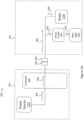
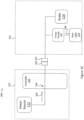
Figs. 2A-2C are a schematic diagrams of an exemplary configuration for operating a brake and a rear light of a vehicle such as the vehicle shown inFig. 1 ; -
Fig. 3A is a schematic diagram of a rear light for use with a vehicle such as the vehicle shown inFig. 1 ; and -
Figs. 3B-3D are additional schematic diagrams of the rear light as shown inFigure 3A . - There has been a dramatic increase in popularity of modular personal mobility vehicles over the last several decades. This increase is due to many factors including the advent of new structural techniques and materials, as well as a more active aging population that enjoys traveling. There is also an increased demand for additional components and features for safety, such as rear lights and rear brakes. Such mobility vehicles may be modular, where a rear assembly is detached from a front assembly to allow for more compact storage such as fitting in the trunk of a car. However, a problem arises when the lighting components are in the rear modular assembly and require electrical power from a power source located in the front modular assembly. When the power source for the vehicle is located in the front modular assembly of the vehicle, powering components in a rear modular assembly can require adding dedicated connections for each component, which can dramatically increase manufacturing costs. Requiring dedicated connections can also make connecting the front and rear modular assemblies more difficult because each of the dedicated connections can fail to mate correctly when the rear modular assembly is coupled to the front modular assembly. Thus it would be desirable to minimize the number of connections between the front and rear modular assemblies while maximizing the number electrically-powered components in the rear modular assembly.
- Referring to the drawings in detail, wherein like reference numerals indicate like elements throughout, there is shown in
Figs. 1-3D avehicle 100 having acontroller 120 for powering components in a rear modular assembly, generally designated 104, in accordance with an exemplary embodiment of the present invention. -
Figure 1 illustrates a perspective view of avehicle 100 in accordance with at least one embodiment of the invention. - The
vehicle 100 includes a frontmodular assembly 102 and a rearmodular assembly 104. The frontmodular assembly 102 may be detachably couplable to the rearmodular assembly 104. In one embodiment,hooks 103a from one assembly such as the frontmodular assembly 102 as shown engage with a feature such as a bar on the other assembly (not shown). The weight of thevehicle 100 may keep front and rearmodular assemblies modular assembly 102 is lifted to detach the two components from one another. In other embodiments, one or more fasteners, latches or locks may be used to releasably couple the frontmodular assembly 102 to the rearmodular assembly 104. Mating thepin connector 105 from the frontmodular assembly 102 with a corresponding pin connector (not shown) in the rearmodular assembly 104 may also help to releasably couple the front and rearmodular assemblies vehicle 100 can be quickly and easily assembled and taken apart for storage or for being transported in another vehicle such as the trunk of a car. - The front
modular assembly 102 includes at least one front wheel (e.g., front wheel 106). InFigure 1 , the frontmodular assembly 102 includes a second front wheel (not shown) laterally spaced from and parallel to thefront wheel 106. The frontmodular assembly 102 includes asteering assembly 108 configured to steer thefront wheel 106. InFigure 1 , thesteering assembly 108 is a tiller that a user grasps with both hands and steers or turns the tiller along a generally vertical axis in the direction that the user wants the vehicle to turn. - The front
modular assembly 102 includes athrottle 110. Thethrottle 110 is controllable by a user. In one embodiment, thethrottle 110 is coupled to thesteering assembly 102. The throttle may be a lever, switch or grip that the user actuates with his or her hand. While activated, thethrottle 110 may be configured to drive one or more rear wheels of thevehicle 100. While released, thethrottle 110 may be configured to refrain from driving thevehicle 100. In one embodiment, releasing thethrottle 110 engages a brake on the one or morerear wheels 114 as described in further detail below. In one embodiment, asingle throttle 110 is provided for controlling tworear wheels 114. - The front
modular assembly 102 includes apower source 112. In some embodiments, thepower source 112 includes one or more batteries, such asbatteries power source 112 is removable. For example, in some embodiments, one or more fasteners, latches or locks are used to releasably couple the power source 112 (e.g.,batteries modular assembly 102. Thepower source 112 may be configured to generate a power signal to drive one or more wheels (e.g.,front wheel 106 and/or rear wheel 114) of thevehicle 100 as well as power other components of thevehicle 100. - The rear
modular assembly 104 includes at least one rear wheel (e.g., rear wheel 114). InFigure 1 , the rearmodular assembly 104 includes a second rear wheel (not shown) laterally spaced from and parallel torear wheel 114. In response to activation of thethrottle 110, the rear wheels may be configured to drive the vehicle 100 (via one or more motors) in either forward or backward directions. - The rear
modular assembly 104 may include abrake 116 that may be configured to operate in an engage state and a disengage state. In the engage state, thebrake 116 may be configured to hold thevehicle 100 in a braking static state by engaging therear wheel 114. In the disengage state, thebrake 116 may be configured to refrain from holding thevehicle 100 in a braking static state by disengaging from therear wheel 114. In some embodiments, thebrake 116 is configured to operate in the engage state while receiving a power signal and operate in a disengage state while not receiving a power signal (or vice versa in alternative embodiments). In some embodiments, thebrake 116 includes a solenoid. In some embodiments, the solenoid may cause thebrake 116 to restrict motion of therear wheel 114 in the engaged state while not receiving the power signal and cause thebrake 116 to disengage from therear wheel 114 while receiving the power signal. In some embodiments, thebrake 116 may include an actuator (e.g., a lever) that is used to manually mechanically engage or disengage a drive motor connected to therear wheel 114 to drive therear wheel 114 to allow a person to push thevehicle 100 without resistance of the motor. In some embodiments, when the throttle is released, resistance from the drive motor connected to therear wheel 114 causes therear wheel 114 to slow, thereby causing thevehicle 100 to come to a stop. In some embodiments, when the throttle is released, the drive motor is also configured to recharge thepower source 112. - The rear
modular assembly 104 includes at least onerear light 118 that may be configured to emit light in certain circumstances. Therear light 118 is configured to emit light in response to receiving a power signal. - The
brake 116 and therear light 118 are configured to be in electrical communication with thepower source 112 while the rearmodular assembly 104 is coupled to the frontmodular assembly 102. In some embodiments, thebrake 116 and therear light 118 are in electrical communication with thepower source 112 via a single shared connection. In some embodiments, the single shared connection isconnector 105 in the frontmodular assembly 102 that mates with a corresponding connector (not shown) in the rearmodular assembly 104. In some embodiments, theconnector 105 is a 4-pin connector. However, it is contemplated that other embodiments may utilize a different number of pins in theconnector 105. In some embodiments, the number of pins may be fewer than 4. Using a single shared connection, depending on when the power signal is selectively received, thebrake 116 may be configured to operate in its engage and disengage states while therear light 118 is configured to emit light. By using a single shared connection, costs for electrical connections between some of the electrical components in therear assembly 104 can be reduced by eliminating the need to include a dedicated connection for each electrical component. Also, fewer connections may reduce the likelihood of poor engagement when the connector from thefront assembly 102 is mated with the connector from therear assembly 104. - The
vehicle 100 includes acontroller 120 in electrical communication with thepower source 112. Thecontroller 120 may be configured to selectively provide a power signal from thepower source 112 to thebrake 116 and the at least onerear light 118 via the single shared connection in certain circumstances. For example, in some embodiments, while the throttle is activated, thecontroller 120 causes thebrake 116 to receive the power signal, and thereby causes thebrake 116 to disengage from therear wheel 114 in the disengage state so that the user can drive thevehicle 100. In some embodiments, while thethrottle 110 is released, thecontroller 120 prevents thebrake 116 from receiving the power signal, and thereby causes thebrake 116 to engage (or restrict motion of) therear wheel 114 in the engage state to hold thevehicle 100 in a braking static state. In some embodiments, while the throttle is activated, thecontroller 120 causes therear light 118 to receive the power signal. In some embodiments, therear light 118 operates as running lights that emit light while thevehicle 100 is being driven. In some embodiments, while the throttle is released, thecontroller 120 prevents therear light 118 from receiving the power signal thereby causes therear light 118 to refrain from emitting light. Using such a configuration, thevehicle 100 may operate thebrake 116 and therear light 118 using a single connection, thereby minimizing the total number of electrical connections between electrical components in the rearmodular assembly 104 and thepower source 112 in the frontmodular assembly 102. -
Figures 2A-2C illustrate a schematic representation of anexemplary lighting assembly 200 configuration for operating thebrake 116 and therear light 118, using thecontroller 120 andpower source 112 of a vehicle such as the vehicle shown inFigure 1 . - The
lighting assembly 200 includes thepower source 112 and thecontroller 120 positioned in the frontmodular assembly 102. Thelighting assembly 200 also includes thebrake 116 and therear light 118 positioned, in parallel, in the rearmodular assembly 104. Thelighting assembly 200 may also include theconnector 105 associated with the frontmodular assembly 102 that, when coupled with anotherconnector 107 associated with the rearmodular assembly 104, allows thebrake 116 and therear light 118 to be in electrical communication with thecontroller 120 andpower source 112. - In
Figure 2A , while not shown, thethrottle 110 of thevehicle 100 is in an activated state because the user desires to drive thevehicle 100. While thethrottle 110 is in the activated state, thepower source 112 provides a power signal (represented asarrows 204 and referred to herein as power signal 204) to thecontroller 120. Because thethrottle 110 is in the activated state, thecontroller 120 may provide thepower signal 204 to thebrake 116 and therear light 118. By providing thepower signal 204 to thebrake 116, thecontroller 120 may cause thebrake 116 to operate in the disengage state. As a result, thebrake 116 may disengage from therear wheel 114 so that the user can drive thevehicle 100. By providing thepower signal 204 to therear light 118, thecontroller 120 may cause therear light 118 to emit light. - While the
controller 120 provides thepower signal 204 to thebrake 116 andrear light 118, thecontroller 120 stores residual energy from the power signal inenergy storage 202, that is not used by thebrake 116 or therear light 118, while the throttle is in the activated state. The residual energy can be used to provide power to the electrical components in the rearmodular assembly 104, such as therear light 118 in certain circumstances, and as described below in more detail. In some embodiments, theenergy storage 202 includes one or more capacitors, super capacitors, chargeable batteries and inductors. In some embodiments, these additional energy storage components may also be appropriate. - In
Figure 2B , while not shown, thethrottle 110 of thevehicle 100 is in a released state because the user desires to stop thevehicle 100. While thethrottle 110 is in the released state, thepower source 112 may provide apower signal 204 to thecontroller 120. However, because thethrottle 110 is in the released state, thecontroller 120 prevents thebrake 116 and therear light 118 from receiving the power signal (represented as "X" 206 inFigure 2B ). By preventing thebrake 116 from receiving thepower signal 204, thecontroller 120 causes thebrake 116 to operate in the engaged state. As a result, thebrake 116 engages (or restricts motion of) therear wheel 114 so that the user can stop and park thevehicle 100. By preventing therear light 118 from receiving thepower signal 204, thecontroller 120 prevents therear light 118 from emitting light based on thepower signal 204. - As shown in
Figure 2C , while the throttle is in the released state, thecontroller 120 provides residual energy (represented asarrows 208 and referred to herein as residual energy 208) from theenergy storage 202 to therear light 118. By providing theresidual energy 208 to therear light 118, thecontroller 120 causes therear light 118 to emit light using the residual energy for a residual energy light emission time period after the throttle transitions from the activated state to the released state. In some embodiments, the residual energy light emission time period is less than 1 minute; less than 50 seconds; less than 40 seconds; less than 30 seconds; less than 20 seconds; less than 10 seconds; less than 5 seconds; or less than 1 second. In some embodiments, the residual energy light emission time period is greater than 1 second; greater than 5 seconds; greater than 10 seconds; greater than 20 seconds; greater than 30 seconds; greater than 40 seconds; greater than 50 seconds; or greater than 1 minute. In some embodiments, the residual energy light emission time period is from 5 to 30 seconds; from 15 to 25 seconds; or approximately 20 seconds. In some embodiments, the residual energy light emission time period depends on an amount of time that the throttle is in the activated state before it transitions to the released state. By causing therear light 118 to emit light after the throttle transitions to the released state, thevehicle 100 may be safer by providing a noticeable visual indicator to motorists or pedestrians that are approaching the vehicle from behind. Also, by causing therear light 118 to emit light after the throttle transitions to the released state, thevehicle 100 may reduce the amount of toggling between an on and off state for therear light 118 associated with activate and release states of the throttle. Because on/off toggling of the lights may lead to degradation of light sources, by minimizing toggling of therear light 118,rear light 118 degradation is minimized and life expectancy for therear light 118 may be improved. -
Figure 3A illustrates an exemplary configuration ofrear light 118 according to at least some embodiments of the invention. - In some embodiments,
rear light 118 is configured to draw a current from the power signal that is less than an electrical current power threshold (e.g., 20 mA). By drawing a current that falls below the electrical current power threshold, therear light 118 can be utilized by thevehicle 100 without interfering with the operation of thebrake 116, which also draws current from the same power signal. In some embodiments,rear light 118 may include one or more light elements, such aslight elements 502a-r as shown inFigure 3A , that draw an amount of current that falls below the electrical current power threshold. Thelight elements 502a-r may be light emitting diodes, but in other embodiments, other types of light elements may be used. In the embodiment, each rear light (such as rear light 118) includes approximately 18 light emitting diodes and operates at approximately 0.25 watts or less. However, it is contemplated that different numbers of light emitting diodes or elements may be used, provided that the total current draw by therear light 118 does not exceed the electrical current power threshold. - In some embodiments,
rear light 118 is configured in, but not limited to, a U-shape, as shown inFigure 3A . However, different configurations are used in other embodiments, including an array, circular, square, triangle, or any other shape that allows therear light 118 to emit light that is visible to a motorist or pedestrian located behind thevehicle 100 or otherwise provides the desired lighting effect. - In some embodiments, the electrical current power threshold is between 1 mA and 50 mA; between 2 mA and 45 mA; between 3 mA and 40 mA; between 4 mA and 35 mA; between 5 mA and 30 mA; between 10 mA and 25 mA; between 15 mA and 25 mA; or approximately 20 mA. In some embodiments, the electrical current power threshold is less than 30 mA; less than 25 mA; less than 20 mA; less than 15 mA; less than 10 mA; less than 5 mA; less than 4 mA; less than 3 mA; less than 2 mA; or less than 1 mA.
- In some embodiments, the total watts of the rear lights (e.g., including rear light 118) is less than 10 W; less than 9.5 W; less than 9.0 W; less than 8.5 W; less than 8.0 W; less than 7.5 W; less than 7.0 W; less than 6.5 W; less than 6.0 W; less than 5.5 W; less than 5.0 W; less than 4.5 W; less than 4.0 W; less than 3.5 W; less than 3.0 W; less than 2.5 W; less than 2.0 W; less than 1.5 W; less than 1.0 W; less than 0.5 W; less than 0.4 W; less than 0.3 W; less than 0.2 W; or less than 0.1 W.
- In some embodiments, one or more of the rear lights satisfy a standard for e-mark lighting for U.S. and/or European use. E-mark standards are provided in "Agreement Concerning the Adoption of Uniform Technical Prescriptions for Wheeled Vehicles, Equipment and Parts which can be Fitted and/or be Used on Wheeled Vehicles and the Conditions for Reciprocal Recognition of Approvals Granted on the Basis of these Prescriptions" dated September 20, 2010.
-
Figures 3B-3D illustrate an exemplary operation ofrear light 118 as shown inFigure 3A according to at least some embodiments of the invention. - In some embodiments, each of the
light elements 502a-r is configured to emit light in a predetermined sequential order. InFigures 3B-3D ,light elements 502a-r are shown as outlined boxes when the light elements do not emit light and are shown as solid boxes when the light elements emit light. In some embodiments, each of thelight elements 502a-r are divided into one or more groups, by area. Thecontroller 120 may be configured to cause a first portion of light elements in the first area to emit light before causing a second portion of the plurality of light elements in the second area to emit light in the predetermined sequential order. In some embodiments, thecontroller 120 includes first, second, and third portions of light elements. In some embodiments, thecontroller 120 may be configured to cause the first portion of light elements to emit light before the second portion of light elements and configured to cause the second portion of light elements to emit light before the third portion of light elements. For example,Figure 3B shows a state of operation of therear light 118 at a time ti;Figure 3C shows a state of operation of therear light 118 at a time t2; andFigure 3D shows a state of operation of therear light 118 at a time t3, where time t2 occurs after time t1 and time t3 occurs after time t2. In this embodiment, therear light 118 includes a first area 504 asecond area 505 and athird area 506.Light elements 502a-502f are arranged in thefirst area 504,light elements 502g-5021 are arranged in thesecond area 505, andlight elements 502m-502r are arranged in thethird area 506. In response to apower signal 204 received from thecontroller 120,light elements 502a-502f in thefirst area 504 initially emit light, as shown inFigure 3B , thenlight elements 502g-5021 in thesecond area 505 emit light, as shown inFigure 3C , and finallylight elements 502m-502r in thethird area 506 emit light, as shown inFigure 3D . In some embodiments, the light elements are configured to emit light in a sequential order by connecting each group of light elements in an area in series with an RC filter. Each RC filter may include resistors and capacitors having different characteristics as compared to other RC filters. By utilizing RC filters with different characteristics, the RC filters may cause the corresponding group of light elements to emit light at different times (e.g., few hundred milliseconds apart). In some embodiments, therear light 118 includes two areas, wherelight elements 502a-502r may be arranged in a first area and second area. In some embodiments,light elements 502a-502i in a top area correspond to afirst area 504 andlight elements 502j-502r in a bottom area correspond to asecond area 504. However, it is contemplated that other areas of therear light 118 may be used for grouping thelight elements 502a-502r, such as a left and right sides of therear light 118, among others. By sequentially causing light elements to emit light, thevehicle 100 can utilize light elements that emit less light while still drawing attention from motorists and pedestrians positioned behind thevehicle 100. - According to the invention the at least one rear light and the brake being in electrical communication with the power source via a shared electrical connection. It is also contemplated that, in other embodiments, different or additional electrical components may share a single connection with the power source 112 (e.g., the brake, rear lights, vehicle backup sensors (e.g., haptic, auditory), rear vehicle cameras, spot light, USB charging port, etc.).
- In at least one embodiment, there is included one or more computers having one or more processors and memory (e.g., one or more nonvolatile storage devices). In some embodiments, memory or computer readable storage medium of memory stores programs, modules and data structures, or a subset thereof for a processor to control and run the various systems and methods disclosed herein. In one embodiment, a non-transitory computer readable storage medium having stored thereon computer-executable instructions which, when executed by a processor, perform one or more of the methods disclosed herein.
- It will be appreciated by those skilled in the art that changes could be made to the exemplary embodiments shown and described above. It is understood, therefore, that this invention is not limited to the exemplary embodiments shown and described, but it is intended to cover modifications within the scope of the present invention as defined by the claims. The words "right", "left", "lower" and "upper" designate directions in the drawings to which reference is made. The words "inwardly" and "outwardly" refer to directions toward and away from, respectively, the geometric center of the
vehicle 100 or any of its components. Unless specifically set forth herein, the terms "a", "an" and "the" are not limited to one element but instead should be read as meaning "at least one". As used herein, the term "about"
may refer to + or - 10% of the value referenced. For example, "about 9" is understood to encompass 8.2 and 9.9. - It is to be understood that at least some of the figures and descriptions of the invention have been simplified to focus on elements that are relevant for a clear understanding of the invention, while eliminating, for purposes of clarity, other elements that those of ordinary skill in the art will appreciate may also comprise a portion of the invention. However, because such elements are well known in the art, and because they do not necessarily facilitate a better understanding of the invention, a description of such elements is not provided herein.
Claims (12)
- A vehicle (100) comprising:a front modular assembly (102) including:at least one front wheel (106),a steering assembly (108) to steer the at least one front wheel (106),a throttle (110) to drive the vehicle (100), anda power source (112) configured to generate a power signal;a rear modular assembly (104) removably couplable to the front modular assembly (102), the rear modular assembly (104) including:at least one rear wheel (114),a brake (116) selectively coupled to the at least one rear wheel (114), andat least one rear light (118) configured to emit light while receiving the power signal, the at least one rear light (118) and the brake (116) being in electrical communication with the power source (112) via a shared electrical connection while the rear modular assembly (104) is coupled to the front modular assembly (102); anda controller (120) in electrical communication with the power source (112), the controller (120) being configured to selectively provide the power signal to the brake (116) and the rear light (118) via the shared electrical connection;wherein the controller (120) includes a storage device that stores residual energy from the power signal while the throttle (110) is activated and wherein the controller (120) causes the at least one rear light (118) to receive the residual energy from the power signal for a residual energy light emission time period after the throttle (110) is released.
- The vehicle (100) of claim 1, wherein the controller (120) is configured to:cause the brake (116) and the at least one rear light (118) to receive the power signal while the throttle (110) is activated, which causes the brake (116) to disengage from the at least one rear wheel (114) and causes the at least one rear light (118) to emit light, andprevent the brake (116) and the at least one rear light (118) from receiving the power signal while the throttle (110) is released, which causes the brake (116) to engage the at least one rear wheel (114) and causes the at least one rear light (118) to refrain from emitting light using the power signal.
- The vehicle (100) of claim 1, wherein the brake (116) includes a solenoid that causes the brake (116) to restrict motion of the at least one rear wheel (114) in the engage state while not receiving the power signal and causes the brake (116) to disengage from the at least one rear wheel (114) while receiving the power signal.
- The vehicle (100) of claim 1, wherein the storage device includes one or more capacitors.
- The vehicle (100) of claim 1, wherein the residual energy light emission time period is from 5 to 30 seconds.
- The vehicle (100) of claim 1, wherein the at least one rear light (118) draws a current from the power signal and wherein the current from the power signal is less than an electrical current power threshold.
- The vehicle (100) of claim 1, wherein the at least one rear light (118) includes a plurality of light elements (502a-r) and wherein each of the plurality of light elements (502a-r) emit light in a predetermined sequential order.
- The vehicle (100) of claim 7, wherein the at least one light (118) includes a first area and a second area, wherein a first portion of the plurality of light elements (502a-r) are arranged in the first area and a second portion of the plurality of light elements (502a-r) are arranged in the second area and wherein the controller (120) is configured to cause the first portion of the plurality of light elements (502a-r) in the first area to emit light before causing the second of the plurality of light elements (502a-r) in the second area to emit light in the predetermined sequential order.
- The vehicle (100) of claim 8, wherein the first area is a top area of the at least one rear light (118) and the second area is the bottom area of the at least one rear light (118).
- The vehicle (100) of claim 8, wherein the first area is a first side area of the at least one rear light (118) and the second area is a second side area of the at least one light (118).
- The vehicle (100) of claim 10, wherein the first side area is a left side of the at least one rear light (118) and wherein the second side area is a right side of the at least one light (118).
- The vehicle (100) of claim 7, wherein the at least one light (118) includes a first area, a second area and a third area,wherein a first portion of the plurality of light elements are arranged in the first area, a second portion of the plurality of light elements are arranged in the second area, and a third portion of the plurality of light elements are arranged in the third area, andwherein the controller (120) is configured to cause the first portion of the plurality of light elements (502a-r) in the first area to emit light before causing the of the plurality of light elements (502a-r) in the second area to emit light and configured to cause the second portion of the plurality of light elements (502a-r) in the second area to emit light before causing the third portion of the plurality of light elements (502a-r) in the third area to emit light, in the predetermined sequential order.
Applications Claiming Priority (2)
| Application Number | Priority Date | Filing Date | Title |
|---|---|---|---|
| US201762463623P | 2017-02-25 | 2017-02-25 | |
| PCT/US2018/019216 WO2018156757A1 (en) | 2017-02-25 | 2018-02-22 | Vehicle integrated storage power management system |
Publications (3)
| Publication Number | Publication Date |
|---|---|
| EP3585345A1 EP3585345A1 (en) | 2020-01-01 |
| EP3585345A4 EP3585345A4 (en) | 2020-12-09 |
| EP3585345B1 true EP3585345B1 (en) | 2024-07-03 |
Family
ID=63253035
Family Applications (1)
| Application Number | Title | Priority Date | Filing Date |
|---|---|---|---|
| EP18757627.7A Active EP3585345B1 (en) | 2017-02-25 | 2018-02-22 | Vehicle integrated storage power management system |
Country Status (6)
| Country | Link |
|---|---|
| US (1) | US10919443B2 (en) |
| EP (1) | EP3585345B1 (en) |
| CN (1) | CN110545774A (en) |
| AU (1) | AU2018224105B2 (en) |
| CA (1) | CA3054145C (en) |
| WO (1) | WO2018156757A1 (en) |
Families Citing this family (3)
| Publication number | Priority date | Publication date | Assignee | Title |
|---|---|---|---|---|
| TWI663086B (en) * | 2018-06-20 | 2019-06-21 | 宏碁股份有限公司 | Braking system for autonomous car and setting method thereof |
| EP4489712A2 (en) * | 2022-03-08 | 2025-01-15 | Pride Mobility Products Corporation | Foldable vehicle |
| USD1033279S1 (en) | 2022-08-22 | 2024-07-02 | Three Oceans, LLC | Scooter |
Citations (1)
| Publication number | Priority date | Publication date | Assignee | Title |
|---|---|---|---|---|
| US20150137481A1 (en) * | 2013-11-21 | 2015-05-21 | Doug Manternach | Suspension for scooter |
Family Cites Families (14)
| Publication number | Priority date | Publication date | Assignee | Title |
|---|---|---|---|---|
| US5020624A (en) * | 1989-11-13 | 1991-06-04 | Everest & Jennings, Inc. | Power drive scooter |
| US6866109B2 (en) * | 2002-08-14 | 2005-03-15 | Thomas Roach | Mobility vehicle |
| WO2007068000A2 (en) * | 2005-12-09 | 2007-06-14 | Abraham Vasant | Apparatus and system for efficient and maneuverable vehicle |
| US7782185B1 (en) * | 2007-08-14 | 2010-08-24 | Burns Dan M | Progressive brake light apparatus |
| JP5046842B2 (en) | 2007-10-04 | 2012-10-10 | 本田技研工業株式会社 | Small electric vehicle |
| EP2390135A1 (en) | 2010-05-26 | 2011-11-30 | Long Jing International Technology Enterprise Co., Ltd. | Control device for vehicle turn lights |
| US9090207B2 (en) * | 2010-05-27 | 2015-07-28 | Boxx Corp. | Two wheeled vehicle with lighting system that generates defined image on riding surface |
| US8733482B2 (en) * | 2010-05-27 | 2014-05-27 | Boxx Corp. | Motor assembly for two wheeled vehicle |
| US8950564B1 (en) * | 2011-08-24 | 2015-02-10 | Ernest Peter Penner | Transmission brake disengagement switch and method of operation |
| US20130264941A1 (en) * | 2012-04-10 | 2013-10-10 | Slava Osherov | Automotive device controlling operation of optional tail lights equipment |
| US10046695B2 (en) * | 2013-09-06 | 2018-08-14 | Judson Smith | Vehicle visibility system |
| DE102013218601A1 (en) * | 2013-09-17 | 2015-04-02 | Siemens Aktiengesellschaft | Energy storage device, energy storage system and method for operating an energy storage device |
| US9187031B1 (en) | 2014-06-24 | 2015-11-17 | Gm Global Technology Operations | Tail light assembly for a vehicle |
| US9238432B1 (en) | 2015-08-20 | 2016-01-19 | Genesis Systems, LLC | Customizable modulator for vehicular braking indication |
-
2018
- 2018-02-22 WO PCT/US2018/019216 patent/WO2018156757A1/en not_active Ceased
- 2018-02-22 CA CA3054145A patent/CA3054145C/en active Active
- 2018-02-22 AU AU2018224105A patent/AU2018224105B2/en active Active
- 2018-02-22 US US16/488,522 patent/US10919443B2/en active Active
- 2018-02-22 EP EP18757627.7A patent/EP3585345B1/en active Active
- 2018-02-22 CN CN201880026953.1A patent/CN110545774A/en active Pending
Patent Citations (1)
| Publication number | Priority date | Publication date | Assignee | Title |
|---|---|---|---|---|
| US20150137481A1 (en) * | 2013-11-21 | 2015-05-21 | Doug Manternach | Suspension for scooter |
Also Published As
| Publication number | Publication date |
|---|---|
| US10919443B2 (en) | 2021-02-16 |
| EP3585345A1 (en) | 2020-01-01 |
| WO2018156757A1 (en) | 2018-08-30 |
| CN110545774A (en) | 2019-12-06 |
| AU2018224105A1 (en) | 2019-09-19 |
| CA3054145C (en) | 2023-08-22 |
| CA3054145A1 (en) | 2018-08-30 |
| EP3585345A4 (en) | 2020-12-09 |
| US20200039424A1 (en) | 2020-02-06 |
| AU2018224105B2 (en) | 2020-01-23 |
Similar Documents
| Publication | Publication Date | Title |
|---|---|---|
| EP3585345B1 (en) | Vehicle integrated storage power management system | |
| US9302723B1 (en) | Interchangeable power train system for electric powered vehicles | |
| CN108263213B (en) | Control of electric brakes of utility vehicles with lithium battery management systems | |
| US6095268A (en) | Children's ride-on vehicle with independently driven and reversible wheels | |
| CN109562691B (en) | Wheel assembly | |
| DE112018004293B4 (en) | Saddle type electric vehicle | |
| US6386304B1 (en) | Electric vehicle with electric-free driving system | |
| US10569655B2 (en) | Electrical motor scooter | |
| CN108263228A (en) | Controlling electrical pathways to lithium batteries on utility vehicles | |
| NO801062L (en) | ELECTRIC VEHICLE. | |
| CN108422806B (en) | Intelligent brake device and system for box wheels with multiple control modes | |
| DE102010014095A1 (en) | Vehicle module i.e. trailer module, for e.g. electric car, has energy storage for storing electrical power, and wheels arranged at wheel axle and driven by drive train, where vehicle module is coupled at vehicle front of motor car | |
| DE112017007897B4 (en) | ELECTRIC VEHICLE OF THE SEMI-TYPE | |
| DE102022126626A1 (en) | ADJUSTABLE ELECTRIC VEHICLE POWER SYSTEMS | |
| CN214240946U (en) | an electric cart | |
| DE202012100199U1 (en) | Hand-guided vehicle | |
| CN210872564U (en) | Wheelchair removes auxiliary device | |
| DE10239499A1 (en) | A vehicle ready for a card key and a radio communication system using a card key | |
| CN208244070U (en) | A kind of Segway Human Transporter | |
| KR102483691B1 (en) | Electric Traveling Device | |
| DE102012100435A1 (en) | Hand-operated vehicle such as baby stroller or luggage trolley, has three wheels, where wheel is detachably fastened in vehicle or is fixed to swing arm, and swing arm is equipped with wheel with electric hub drive | |
| CN210205134U (en) | Intelligent boosting wheel with linear controller for hand-push wheelchair | |
| JPS58122260A (en) | Extensible and contractible combination vehicle | |
| KR20150075933A (en) | Electric bicycle comprising universal serial bus charging connector | |
| CN106004460A (en) | Five-wheel vehicle braking system |
Legal Events
| Date | Code | Title | Description |
|---|---|---|---|
| STAA | Information on the status of an ep patent application or granted ep patent |
Free format text: STATUS: THE INTERNATIONAL PUBLICATION HAS BEEN MADE |
|
| PUAI | Public reference made under article 153(3) epc to a published international application that has entered the european phase |
Free format text: ORIGINAL CODE: 0009012 |
|
| STAA | Information on the status of an ep patent application or granted ep patent |
Free format text: STATUS: REQUEST FOR EXAMINATION WAS MADE |
|
| 17P | Request for examination filed |
Effective date: 20190909 |
|
| AK | Designated contracting states |
Kind code of ref document: A1 Designated state(s): AL AT BE BG CH CY CZ DE DK EE ES FI FR GB GR HR HU IE IS IT LI LT LU LV MC MK MT NL NO PL PT RO RS SE SI SK SM TR |
|
| AX | Request for extension of the european patent |
Extension state: BA ME |
|
| DAV | Request for validation of the european patent (deleted) | ||
| DAX | Request for extension of the european patent (deleted) | ||
| A4 | Supplementary search report drawn up and despatched |
Effective date: 20201105 |
|
| RIC1 | Information provided on ipc code assigned before grant |
Ipc: B60Q 1/44 20060101ALI20201030BHEP Ipc: A61G 5/04 20130101AFI20201030BHEP Ipc: B60T 7/08 20060101ALI20201030BHEP |
|
| STAA | Information on the status of an ep patent application or granted ep patent |
Free format text: STATUS: EXAMINATION IS IN PROGRESS |
|
| 17Q | First examination report despatched |
Effective date: 20220923 |
|
| P01 | Opt-out of the competence of the unified patent court (upc) registered |
Effective date: 20230518 |
|
| RAP3 | Party data changed (applicant data changed or rights of an application transferred) |
Owner name: PRIDE MOBILITY PRODUCTS CORPORATION |
|
| GRAP | Despatch of communication of intention to grant a patent |
Free format text: ORIGINAL CODE: EPIDOSNIGR1 |
|
| STAA | Information on the status of an ep patent application or granted ep patent |
Free format text: STATUS: GRANT OF PATENT IS INTENDED |
|
| INTG | Intention to grant announced |
Effective date: 20240215 |
|
| GRAS | Grant fee paid |
Free format text: ORIGINAL CODE: EPIDOSNIGR3 |
|
| GRAA | (expected) grant |
Free format text: ORIGINAL CODE: 0009210 |
|
| STAA | Information on the status of an ep patent application or granted ep patent |
Free format text: STATUS: THE PATENT HAS BEEN GRANTED |
|
| AK | Designated contracting states |
Kind code of ref document: B1 Designated state(s): AL AT BE BG CH CY CZ DE DK EE ES FI FR GB GR HR HU IE IS IT LI LT LU LV MC MK MT NL NO PL PT RO RS SE SI SK SM TR |
|
| REG | Reference to a national code |
Ref country code: CH Ref legal event code: EP |
|
| REG | Reference to a national code |
Ref country code: DE Ref legal event code: R096 Ref document number: 602018071305 Country of ref document: DE |
|
| REG | Reference to a national code |
Ref country code: NL Ref legal event code: FP |
|
| REG | Reference to a national code |
Ref country code: LT Ref legal event code: MG9D |
|
| PG25 | Lapsed in a contracting state [announced via postgrant information from national office to epo] |
Ref country code: PT Free format text: LAPSE BECAUSE OF FAILURE TO SUBMIT A TRANSLATION OF THE DESCRIPTION OR TO PAY THE FEE WITHIN THE PRESCRIBED TIME-LIMIT Effective date: 20241104 |
|
| REG | Reference to a national code |
Ref country code: AT Ref legal event code: MK05 Ref document number: 1699067 Country of ref document: AT Kind code of ref document: T Effective date: 20240703 |
|
| PG25 | Lapsed in a contracting state [announced via postgrant information from national office to epo] |
Ref country code: PT Free format text: LAPSE BECAUSE OF FAILURE TO SUBMIT A TRANSLATION OF THE DESCRIPTION OR TO PAY THE FEE WITHIN THE PRESCRIBED TIME-LIMIT Effective date: 20241104 |
|
| PG25 | Lapsed in a contracting state [announced via postgrant information from national office to epo] |
Ref country code: NO Free format text: LAPSE BECAUSE OF FAILURE TO SUBMIT A TRANSLATION OF THE DESCRIPTION OR TO PAY THE FEE WITHIN THE PRESCRIBED TIME-LIMIT Effective date: 20241003 |
|
| PG25 | Lapsed in a contracting state [announced via postgrant information from national office to epo] |
Ref country code: PL Free format text: LAPSE BECAUSE OF FAILURE TO SUBMIT A TRANSLATION OF THE DESCRIPTION OR TO PAY THE FEE WITHIN THE PRESCRIBED TIME-LIMIT Effective date: 20240703 Ref country code: FI Free format text: LAPSE BECAUSE OF FAILURE TO SUBMIT A TRANSLATION OF THE DESCRIPTION OR TO PAY THE FEE WITHIN THE PRESCRIBED TIME-LIMIT Effective date: 20240703 Ref country code: GR Free format text: LAPSE BECAUSE OF FAILURE TO SUBMIT A TRANSLATION OF THE DESCRIPTION OR TO PAY THE FEE WITHIN THE PRESCRIBED TIME-LIMIT Effective date: 20241004 |
|
| PG25 | Lapsed in a contracting state [announced via postgrant information from national office to epo] |
Ref country code: BG Free format text: LAPSE BECAUSE OF FAILURE TO SUBMIT A TRANSLATION OF THE DESCRIPTION OR TO PAY THE FEE WITHIN THE PRESCRIBED TIME-LIMIT Effective date: 20240703 |
|
| PG25 | Lapsed in a contracting state [announced via postgrant information from national office to epo] |
Ref country code: LV Free format text: LAPSE BECAUSE OF FAILURE TO SUBMIT A TRANSLATION OF THE DESCRIPTION OR TO PAY THE FEE WITHIN THE PRESCRIBED TIME-LIMIT Effective date: 20240703 |
|
| PG25 | Lapsed in a contracting state [announced via postgrant information from national office to epo] |
Ref country code: IS Free format text: LAPSE BECAUSE OF FAILURE TO SUBMIT A TRANSLATION OF THE DESCRIPTION OR TO PAY THE FEE WITHIN THE PRESCRIBED TIME-LIMIT Effective date: 20241103 Ref country code: AT Free format text: LAPSE BECAUSE OF FAILURE TO SUBMIT A TRANSLATION OF THE DESCRIPTION OR TO PAY THE FEE WITHIN THE PRESCRIBED TIME-LIMIT Effective date: 20240703 |
|
| PG25 | Lapsed in a contracting state [announced via postgrant information from national office to epo] |
Ref country code: CZ Free format text: LAPSE BECAUSE OF FAILURE TO SUBMIT A TRANSLATION OF THE DESCRIPTION OR TO PAY THE FEE WITHIN THE PRESCRIBED TIME-LIMIT Effective date: 20240703 Ref country code: HR Free format text: LAPSE BECAUSE OF FAILURE TO SUBMIT A TRANSLATION OF THE DESCRIPTION OR TO PAY THE FEE WITHIN THE PRESCRIBED TIME-LIMIT Effective date: 20240703 |
|
| PG25 | Lapsed in a contracting state [announced via postgrant information from national office to epo] |
Ref country code: RS Free format text: LAPSE BECAUSE OF FAILURE TO SUBMIT A TRANSLATION OF THE DESCRIPTION OR TO PAY THE FEE WITHIN THE PRESCRIBED TIME-LIMIT Effective date: 20241003 Ref country code: ES Free format text: LAPSE BECAUSE OF FAILURE TO SUBMIT A TRANSLATION OF THE DESCRIPTION OR TO PAY THE FEE WITHIN THE PRESCRIBED TIME-LIMIT Effective date: 20240703 |
|
| PG25 | Lapsed in a contracting state [announced via postgrant information from national office to epo] |
Ref country code: RS Free format text: LAPSE BECAUSE OF FAILURE TO SUBMIT A TRANSLATION OF THE DESCRIPTION OR TO PAY THE FEE WITHIN THE PRESCRIBED TIME-LIMIT Effective date: 20241003 Ref country code: PL Free format text: LAPSE BECAUSE OF FAILURE TO SUBMIT A TRANSLATION OF THE DESCRIPTION OR TO PAY THE FEE WITHIN THE PRESCRIBED TIME-LIMIT Effective date: 20240703 Ref country code: NO Free format text: LAPSE BECAUSE OF FAILURE TO SUBMIT A TRANSLATION OF THE DESCRIPTION OR TO PAY THE FEE WITHIN THE PRESCRIBED TIME-LIMIT Effective date: 20241003 Ref country code: LV Free format text: LAPSE BECAUSE OF FAILURE TO SUBMIT A TRANSLATION OF THE DESCRIPTION OR TO PAY THE FEE WITHIN THE PRESCRIBED TIME-LIMIT Effective date: 20240703 Ref country code: IS Free format text: LAPSE BECAUSE OF FAILURE TO SUBMIT A TRANSLATION OF THE DESCRIPTION OR TO PAY THE FEE WITHIN THE PRESCRIBED TIME-LIMIT Effective date: 20241103 Ref country code: HR Free format text: LAPSE BECAUSE OF FAILURE TO SUBMIT A TRANSLATION OF THE DESCRIPTION OR TO PAY THE FEE WITHIN THE PRESCRIBED TIME-LIMIT Effective date: 20240703 Ref country code: GR Free format text: LAPSE BECAUSE OF FAILURE TO SUBMIT A TRANSLATION OF THE DESCRIPTION OR TO PAY THE FEE WITHIN THE PRESCRIBED TIME-LIMIT Effective date: 20241004 Ref country code: FI Free format text: LAPSE BECAUSE OF FAILURE TO SUBMIT A TRANSLATION OF THE DESCRIPTION OR TO PAY THE FEE WITHIN THE PRESCRIBED TIME-LIMIT Effective date: 20240703 Ref country code: ES Free format text: LAPSE BECAUSE OF FAILURE TO SUBMIT A TRANSLATION OF THE DESCRIPTION OR TO PAY THE FEE WITHIN THE PRESCRIBED TIME-LIMIT Effective date: 20240703 Ref country code: CZ Free format text: LAPSE BECAUSE OF FAILURE TO SUBMIT A TRANSLATION OF THE DESCRIPTION OR TO PAY THE FEE WITHIN THE PRESCRIBED TIME-LIMIT Effective date: 20240703 Ref country code: BG Free format text: LAPSE BECAUSE OF FAILURE TO SUBMIT A TRANSLATION OF THE DESCRIPTION OR TO PAY THE FEE WITHIN THE PRESCRIBED TIME-LIMIT Effective date: 20240703 Ref country code: AT Free format text: LAPSE BECAUSE OF FAILURE TO SUBMIT A TRANSLATION OF THE DESCRIPTION OR TO PAY THE FEE WITHIN THE PRESCRIBED TIME-LIMIT Effective date: 20240703 |
|
| REG | Reference to a national code |
Ref country code: DE Ref legal event code: R097 Ref document number: 602018071305 Country of ref document: DE |
|
| PG25 | Lapsed in a contracting state [announced via postgrant information from national office to epo] |
Ref country code: RO Free format text: LAPSE BECAUSE OF FAILURE TO SUBMIT A TRANSLATION OF THE DESCRIPTION OR TO PAY THE FEE WITHIN THE PRESCRIBED TIME-LIMIT Effective date: 20240703 Ref country code: SM Free format text: LAPSE BECAUSE OF FAILURE TO SUBMIT A TRANSLATION OF THE DESCRIPTION OR TO PAY THE FEE WITHIN THE PRESCRIBED TIME-LIMIT Effective date: 20240703 Ref country code: DK Free format text: LAPSE BECAUSE OF FAILURE TO SUBMIT A TRANSLATION OF THE DESCRIPTION OR TO PAY THE FEE WITHIN THE PRESCRIBED TIME-LIMIT Effective date: 20240703 |
|
| PG25 | Lapsed in a contracting state [announced via postgrant information from national office to epo] |
Ref country code: EE Free format text: LAPSE BECAUSE OF FAILURE TO SUBMIT A TRANSLATION OF THE DESCRIPTION OR TO PAY THE FEE WITHIN THE PRESCRIBED TIME-LIMIT Effective date: 20240703 |
|
| PG25 | Lapsed in a contracting state [announced via postgrant information from national office to epo] |
Ref country code: SK Free format text: LAPSE BECAUSE OF FAILURE TO SUBMIT A TRANSLATION OF THE DESCRIPTION OR TO PAY THE FEE WITHIN THE PRESCRIBED TIME-LIMIT Effective date: 20240703 |
|
| PLBE | No opposition filed within time limit |
Free format text: ORIGINAL CODE: 0009261 |
|
| STAA | Information on the status of an ep patent application or granted ep patent |
Free format text: STATUS: NO OPPOSITION FILED WITHIN TIME LIMIT |
|
| 26N | No opposition filed |
Effective date: 20250404 |
|
| PG25 | Lapsed in a contracting state [announced via postgrant information from national office to epo] |
Ref country code: SE Free format text: LAPSE BECAUSE OF FAILURE TO SUBMIT A TRANSLATION OF THE DESCRIPTION OR TO PAY THE FEE WITHIN THE PRESCRIBED TIME-LIMIT Effective date: 20240703 |
|
| PG25 | Lapsed in a contracting state [announced via postgrant information from national office to epo] |
Ref country code: MC Free format text: LAPSE BECAUSE OF FAILURE TO SUBMIT A TRANSLATION OF THE DESCRIPTION OR TO PAY THE FEE WITHIN THE PRESCRIBED TIME-LIMIT Effective date: 20240703 |
|
| REG | Reference to a national code |
Ref country code: CH Ref legal event code: PL |
|
| PG25 | Lapsed in a contracting state [announced via postgrant information from national office to epo] |
Ref country code: LU Free format text: LAPSE BECAUSE OF NON-PAYMENT OF DUE FEES Effective date: 20250222 |
|
| PG25 | Lapsed in a contracting state [announced via postgrant information from national office to epo] |
Ref country code: CH Free format text: LAPSE BECAUSE OF NON-PAYMENT OF DUE FEES Effective date: 20250228 |
|
| REG | Reference to a national code |
Ref country code: BE Ref legal event code: MM Effective date: 20250228 |
|
| PG25 | Lapsed in a contracting state [announced via postgrant information from national office to epo] |
Ref country code: BE Free format text: LAPSE BECAUSE OF NON-PAYMENT OF DUE FEES Effective date: 20250228 |
|
| PG25 | Lapsed in a contracting state [announced via postgrant information from national office to epo] |
Ref country code: IE Free format text: LAPSE BECAUSE OF NON-PAYMENT OF DUE FEES Effective date: 20250222 |
|
| PGFP | Annual fee paid to national office [announced via postgrant information from national office to epo] |
Ref country code: NL Payment date: 20260226 Year of fee payment: 9 |
|
| PGFP | Annual fee paid to national office [announced via postgrant information from national office to epo] |
Ref country code: GB Payment date: 20260227 Year of fee payment: 9 |
|
| PGFP | Annual fee paid to national office [announced via postgrant information from national office to epo] |
Ref country code: DE Payment date: 20251230 Year of fee payment: 9 |
|
| PGFP | Annual fee paid to national office [announced via postgrant information from national office to epo] |
Ref country code: IT Payment date: 20260122 Year of fee payment: 9 |
|
| PGFP | Annual fee paid to national office [announced via postgrant information from national office to epo] |
Ref country code: FR Payment date: 20260225 Year of fee payment: 9 |