EP3585320B2 - Delivery system for radially constricting a stent graft - Google Patents
Delivery system for radially constricting a stent graft Download PDFInfo
- Publication number
- EP3585320B2 EP3585320B2 EP18709882.7A EP18709882A EP3585320B2 EP 3585320 B2 EP3585320 B2 EP 3585320B2 EP 18709882 A EP18709882 A EP 18709882A EP 3585320 B2 EP3585320 B2 EP 3585320B2
- Authority
- EP
- European Patent Office
- Prior art keywords
- stent graft
- wire
- delivery system
- stent
- proximal
- Prior art date
- Legal status (The legal status is an assumption and is not a legal conclusion. Google has not performed a legal analysis and makes no representation as to the accuracy of the status listed.)
- Active
Links
Images


Classifications
-
- A—HUMAN NECESSITIES
- A61—MEDICAL OR VETERINARY SCIENCE; HYGIENE
- A61F—FILTERS IMPLANTABLE INTO BLOOD VESSELS; PROSTHESES; DEVICES PROVIDING PATENCY TO, OR PREVENTING COLLAPSING OF, TUBULAR STRUCTURES OF THE BODY, e.g. STENTS; ORTHOPAEDIC, NURSING OR CONTRACEPTIVE DEVICES; FOMENTATION; TREATMENT OR PROTECTION OF EYES OR EARS; BANDAGES, DRESSINGS OR ABSORBENT PADS; FIRST-AID KITS
- A61F2/00—Filters implantable into blood vessels; Prostheses, i.e. artificial substitutes or replacements for parts of the body; Appliances for connecting them with the body; Devices providing patency to, or preventing collapsing of, tubular structures of the body, e.g. stents
- A61F2/95—Instruments specially adapted for placement or removal of stents or stent-grafts
-
- A—HUMAN NECESSITIES
- A61—MEDICAL OR VETERINARY SCIENCE; HYGIENE
- A61F—FILTERS IMPLANTABLE INTO BLOOD VESSELS; PROSTHESES; DEVICES PROVIDING PATENCY TO, OR PREVENTING COLLAPSING OF, TUBULAR STRUCTURES OF THE BODY, e.g. STENTS; ORTHOPAEDIC, NURSING OR CONTRACEPTIVE DEVICES; FOMENTATION; TREATMENT OR PROTECTION OF EYES OR EARS; BANDAGES, DRESSINGS OR ABSORBENT PADS; FIRST-AID KITS
- A61F2/00—Filters implantable into blood vessels; Prostheses, i.e. artificial substitutes or replacements for parts of the body; Appliances for connecting them with the body; Devices providing patency to, or preventing collapsing of, tubular structures of the body, e.g. stents
- A61F2/02—Prostheses implantable into the body
- A61F2/04—Hollow or tubular parts of organs, e.g. bladders, tracheae, bronchi or bile ducts
- A61F2/06—Blood vessels
- A61F2/07—Stent-grafts
-
- A—HUMAN NECESSITIES
- A61—MEDICAL OR VETERINARY SCIENCE; HYGIENE
- A61F—FILTERS IMPLANTABLE INTO BLOOD VESSELS; PROSTHESES; DEVICES PROVIDING PATENCY TO, OR PREVENTING COLLAPSING OF, TUBULAR STRUCTURES OF THE BODY, e.g. STENTS; ORTHOPAEDIC, NURSING OR CONTRACEPTIVE DEVICES; FOMENTATION; TREATMENT OR PROTECTION OF EYES OR EARS; BANDAGES, DRESSINGS OR ABSORBENT PADS; FIRST-AID KITS
- A61F2/00—Filters implantable into blood vessels; Prostheses, i.e. artificial substitutes or replacements for parts of the body; Appliances for connecting them with the body; Devices providing patency to, or preventing collapsing of, tubular structures of the body, e.g. stents
- A61F2/95—Instruments specially adapted for placement or removal of stents or stent-grafts
- A61F2/954—Instruments specially adapted for placement or removal of stents or stent-grafts for placing stents or stent-grafts in a bifurcation
-
- A—HUMAN NECESSITIES
- A61—MEDICAL OR VETERINARY SCIENCE; HYGIENE
- A61F—FILTERS IMPLANTABLE INTO BLOOD VESSELS; PROSTHESES; DEVICES PROVIDING PATENCY TO, OR PREVENTING COLLAPSING OF, TUBULAR STRUCTURES OF THE BODY, e.g. STENTS; ORTHOPAEDIC, NURSING OR CONTRACEPTIVE DEVICES; FOMENTATION; TREATMENT OR PROTECTION OF EYES OR EARS; BANDAGES, DRESSINGS OR ABSORBENT PADS; FIRST-AID KITS
- A61F2/00—Filters implantable into blood vessels; Prostheses, i.e. artificial substitutes or replacements for parts of the body; Appliances for connecting them with the body; Devices providing patency to, or preventing collapsing of, tubular structures of the body, e.g. stents
- A61F2/95—Instruments specially adapted for placement or removal of stents or stent-grafts
- A61F2/962—Instruments specially adapted for placement or removal of stents or stent-grafts having an outer sleeve
- A61F2/966—Instruments specially adapted for placement or removal of stents or stent-grafts having an outer sleeve with relative longitudinal movement between outer sleeve and prosthesis, e.g. using a push rod
- A61F2/9662—Instruments specially adapted for placement or removal of stents or stent-grafts having an outer sleeve with relative longitudinal movement between outer sleeve and prosthesis, e.g. using a push rod the middle portion of the stent or stent-graft is released first
-
- A—HUMAN NECESSITIES
- A61—MEDICAL OR VETERINARY SCIENCE; HYGIENE
- A61F—FILTERS IMPLANTABLE INTO BLOOD VESSELS; PROSTHESES; DEVICES PROVIDING PATENCY TO, OR PREVENTING COLLAPSING OF, TUBULAR STRUCTURES OF THE BODY, e.g. STENTS; ORTHOPAEDIC, NURSING OR CONTRACEPTIVE DEVICES; FOMENTATION; TREATMENT OR PROTECTION OF EYES OR EARS; BANDAGES, DRESSINGS OR ABSORBENT PADS; FIRST-AID KITS
- A61F2/00—Filters implantable into blood vessels; Prostheses, i.e. artificial substitutes or replacements for parts of the body; Appliances for connecting them with the body; Devices providing patency to, or preventing collapsing of, tubular structures of the body, e.g. stents
- A61F2/95—Instruments specially adapted for placement or removal of stents or stent-grafts
- A61F2/9517—Instruments specially adapted for placement or removal of stents or stent-grafts handle assemblies therefor
-
- A—HUMAN NECESSITIES
- A61—MEDICAL OR VETERINARY SCIENCE; HYGIENE
- A61F—FILTERS IMPLANTABLE INTO BLOOD VESSELS; PROSTHESES; DEVICES PROVIDING PATENCY TO, OR PREVENTING COLLAPSING OF, TUBULAR STRUCTURES OF THE BODY, e.g. STENTS; ORTHOPAEDIC, NURSING OR CONTRACEPTIVE DEVICES; FOMENTATION; TREATMENT OR PROTECTION OF EYES OR EARS; BANDAGES, DRESSINGS OR ABSORBENT PADS; FIRST-AID KITS
- A61F2/00—Filters implantable into blood vessels; Prostheses, i.e. artificial substitutes or replacements for parts of the body; Appliances for connecting them with the body; Devices providing patency to, or preventing collapsing of, tubular structures of the body, e.g. stents
- A61F2/95—Instruments specially adapted for placement or removal of stents or stent-grafts
- A61F2002/9505—Instruments specially adapted for placement or removal of stents or stent-grafts having retaining means other than an outer sleeve, e.g. male-female connector between stent and instrument
- A61F2002/9511—Instruments specially adapted for placement or removal of stents or stent-grafts having retaining means other than an outer sleeve, e.g. male-female connector between stent and instrument the retaining means being filaments or wires
-
- A—HUMAN NECESSITIES
- A61—MEDICAL OR VETERINARY SCIENCE; HYGIENE
- A61F—FILTERS IMPLANTABLE INTO BLOOD VESSELS; PROSTHESES; DEVICES PROVIDING PATENCY TO, OR PREVENTING COLLAPSING OF, TUBULAR STRUCTURES OF THE BODY, e.g. STENTS; ORTHOPAEDIC, NURSING OR CONTRACEPTIVE DEVICES; FOMENTATION; TREATMENT OR PROTECTION OF EYES OR EARS; BANDAGES, DRESSINGS OR ABSORBENT PADS; FIRST-AID KITS
- A61F2/00—Filters implantable into blood vessels; Prostheses, i.e. artificial substitutes or replacements for parts of the body; Appliances for connecting them with the body; Devices providing patency to, or preventing collapsing of, tubular structures of the body, e.g. stents
- A61F2/95—Instruments specially adapted for placement or removal of stents or stent-grafts
- A61F2/962—Instruments specially adapted for placement or removal of stents or stent-grafts having an outer sleeve
- A61F2/966—Instruments specially adapted for placement or removal of stents or stent-grafts having an outer sleeve with relative longitudinal movement between outer sleeve and prosthesis, e.g. using a push rod
- A61F2002/9665—Instruments specially adapted for placement or removal of stents or stent-grafts having an outer sleeve with relative longitudinal movement between outer sleeve and prosthesis, e.g. using a push rod with additional retaining means
-
- A—HUMAN NECESSITIES
- A61—MEDICAL OR VETERINARY SCIENCE; HYGIENE
- A61F—FILTERS IMPLANTABLE INTO BLOOD VESSELS; PROSTHESES; DEVICES PROVIDING PATENCY TO, OR PREVENTING COLLAPSING OF, TUBULAR STRUCTURES OF THE BODY, e.g. STENTS; ORTHOPAEDIC, NURSING OR CONTRACEPTIVE DEVICES; FOMENTATION; TREATMENT OR PROTECTION OF EYES OR EARS; BANDAGES, DRESSINGS OR ABSORBENT PADS; FIRST-AID KITS
- A61F2220/00—Fixations or connections for prostheses classified in groups A61F2/00 - A61F2/26 or A61F2/82 or A61F9/00 or A61F11/00 or subgroups thereof
- A61F2220/0025—Connections or couplings between prosthetic parts, e.g. between modular parts; Connecting elements
- A61F2220/0075—Connections or couplings between prosthetic parts, e.g. between modular parts; Connecting elements sutured, ligatured or stitched, retained or tied with a rope, string, thread, wire or cable
Definitions
- WO 97/03624 A1 relates to adjustable and retrievable graft and graft delivery system for stent-graft system and methods of implantation.
- WO2009148594 A1 discloses controlled deployable medical devices that are retained inside a body passage and in one particular application to vascular devices used in repairing arterial dilations, e.g. aneurysms. Such devices can be adjusted during deployment, thereby allowing at least one of a longitudinal or radial re-positioning, for precise alignment of the device to an implant target site.
- the present invention relates to stent graft delivery systems for use in treating and repairing aortic vascular damage, such as vascular damage associated with aortic aneurysms, including aortic aneurysms in regions of the aorta having arterial branches that supply blood to vital organs and tissues, such as thoracic aortic aneurysms, abdominal aortic aneurysms, thoracoabdominal aortic aneurysms, juxtarenal aortic aneurysms and short-neck abdominal aortic aneurysms.
- aortic vascular damage such as vascular damage associated with aortic aneurysms
- aortic vascular damage associated with aortic aneurysms including aortic aneurysms in regions of the aorta having arterial branches that supply blood to vital organs and tissues, such as thoracic aortic aneurys
- the invention is a method of implanting a stent graft at an aneurysm of a subject, including the step of directing a stent graft to an aneurysm of the subject, and at least one stent of the stent graft being held in a radially constricted position by at least one wire configured as a loop that extends through at least one tube and is at least partially secured to the stent graft in a delivery system.
- the physician can selectively constrict the radial dimension of a partially deployed stent graft, thereby enabling the physician to rotate or otherwise reposition the stent graft after it has been partially deployed, such as by decreasing or increasing tension on at least one wire configured as a loop that is secured to a stent graft, thereby providing greater control over orientation of the stent graft before deployment.
- a stent graft can be deployed at an aneurysm with more accuracy, less risk of injury to the vasculature of the subject, and without significant risk of distorting the intended shape of the stent graft when implanted at the aneurysm.
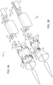
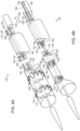
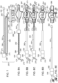
- FIG. 7 is an exploded view of components of another embodiment of a stent graft delivery system of the invention.
- stent graft delivery system 250 has guidewire catheter 252 includes proximal end 254 and distal end 256.
- Proximal handle 258 is fixed to proximal end 254 and nose cone 260 is fixed to distal end 256 of guidewire catheter 252.
- Introducer sheath 262 includes proximal end 264 and distal end 266.
- Distal handle 268 is fixed to proximal end 264 of introducer sheath 262.
- Wires 274,275 have sufficient length to extend from stent graft 218 to proximal handle 258, and are housed in respective tubes 284,286, respectively. Loops 285,287 extend distally from tubes 284,286.
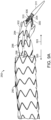
- FIG. 8C which shows stent 276, distal to stent 277, exhibiting radial expansion as a consequence of distal movement of wire 274 in the direction of arrow 289, such as by relaxation of tension of wire 274 having a loop extending about stent 276, causing radial expansion of stent 276. Only stent 277 remains radially constricted, as shown in FIG. 8C .
- stents 276,277 respectively are radially self-expanding, such as where stents are fabricated of a suitable shape memory alloy, such as Nitinol, relaxation of tension on wires 274,275 will cause radial expansion of stents 276,277, respectively.
- stents 276,277 Upon release or distal movement of both wires 274,275 radially constricting each respective stents 276,277 of stent graft 272, stents 276,277 will both exhibit radial expansion to occupy aneurysm 270 of the subject.
- stent graft 272 includes bare stent 280 at proximal end 282 of stent graft 272, bare stent 280 can remain fixed at apex capture assembly 284, as shown in FIG. 8D .
- proximal apices 286 of bare stent 280 by actuation of apex capture assembly 284 causes bare stent 280 to land at a portion of the artery just cranial to aneurysm 270.
- wires 274,275 can be removed at any time following release of tension on wires 274,275 to allow radial expansion of stents 276,277 by, for example, pulling on one end of each wire 274,275 to thereby retract the wire from the remainder of stent graft delivery system 250, or by severing connection of wires 274,275 from proximal handle 258.
- stent graft delivery system 250 can be retracted from within stent graft 272 and from the patient, thereby completing implantation of stent graft 272 and treatment of aneurysm 270, as also shown in FIG. 8E .
- stent graft 272 is positioned so that fenestration 273 is properly aligned with arterial branch 281 for subsequent placement of branch prosthesis 287 through fenestration 273 to arterial branch 281.
- stent graft 272 is fully implanted within aneurysm 270, and the remainder of stent graft delivery system 250 is retracted from stent graft 272 and the patient, as shown in FIG. 8E , thereby completing treatment of aneurysm 270 of the patient by the method of the invention.
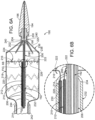
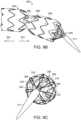
- FIG. 9A is a partial side view of a portion of stent graft prosthesis 290 of stent graft delivery system 292 of the invention showing radial constriction of three stents 294,296,298 by respective wires (not shown) within stent graft prosthesis 290.
- Bare stent 300 at proximal end 302 of prosthesis 290 is fixed at proximal apices 204 of bare stent 300 by apex capture assembly 306.
- guidewire catheter (not shown) is arched, thereby causing stent graft prosthesis 290 to be arched at distal end 310.
- Nose cone 311 is at distal end 310 of the guidewire catheter.
- stent graft prosthesis 290 may define at least one fenestration or scallop (not shown) between constricted stents 294,296,298, which, in this case, are radially self-expanding, whereby radial constriction of stents is determined by the tension on loops threaded through sutures between struts of stents 294,296,298, as is described above.
- Configuring guidewire catheter 308 as an arch at its distal end 310 is beneficial in embodiments where fenestration (not shown) is located at an arcuate arterial blood vessel, such as the aortic arch.
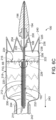
- FIG. 9B is a partial side view of stent graft prosthesis 290 and stent graft delivery system 292 shown in FIG. 9A , wherein two of three wires constricting respective stents 294,296,298 have been released, or moved distally, thereby enabling radial expansion of two stents 294,296 proximal to third stent 294 that remains in a constricted configuration by its respective constraining wire of the stent graft delivery system.
- FIG. 9C is an end view of the embodiment shown in FIG. 9B , wherein most distal wire 318 previously constricting stent 298, is relaxed, or moved distally, but remains threaded through sutures 320 at stent graft 290.
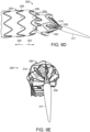
- FIG. 9D is a partial side view of stent graft prosthesis 290 of stent graft delivery system 292 shown in FIG. 9A , wherein tension on wires 314,316 previously constricting stents 294,296 to stent 298 has been relaxed, or moved distally, thereby enabling radial expansion of stents 294,296, while stent 298 remains in a radially constricted position.
- FIG. 9E is an end view of stent graft 290 and delivery system 292 in the arrangement shown in FIG. 9D , wherein wire 318 constricting most proximal stent 298 is still in a constricted position.
- FIG. 9F is a side view of stent graft prosthesis 292 shown in FIGs. 9A through 9E , wherein the tension on all wires 314,316,318 previously constricting stents 294,296,298 has been relaxed.
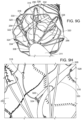
- FIG. 9G is an end view of the configuration of stent graft prosthesis shown in FIG.
Landscapes
- Health & Medical Sciences (AREA)
- Engineering & Computer Science (AREA)
- Biomedical Technology (AREA)
- Cardiology (AREA)
- Oral & Maxillofacial Surgery (AREA)
- Transplantation (AREA)
- Heart & Thoracic Surgery (AREA)
- Vascular Medicine (AREA)
- Life Sciences & Earth Sciences (AREA)
- Animal Behavior & Ethology (AREA)
- General Health & Medical Sciences (AREA)
- Public Health (AREA)
- Veterinary Medicine (AREA)
- Gastroenterology & Hepatology (AREA)
- Pulmonology (AREA)
- Prostheses (AREA)
- Media Introduction/Drainage Providing Device (AREA)
Description
- Aortic pathologies, including aortic aneurysms, can be treated by open surgical reconstruction, or alternatively, endovascular repair, which is a minimally invasive alternative to open surgical repair. Optimizing a successful outcome of endovascular repair, however, requires assessment of the patient's anatomy and, in the case of an aortic aneurysm, an appropriate stent graft that spans the proximal and distal ends of the aneurysm to insure complete exclusion of the aneurysm sac, anchoring of the stent graft in the aorta, and minimal endoleaks. Also, endoleaks and post-surgical enlargement of the aneurysm site can require additional repair to seal any expansion of the aneurysm sac, and, generally, must be done without significantly compromising blood flow through the surgical site to surrounding viscera and associated structures.
-
WO 97/03624 A1 WO2009148594 A1 discloses controlled deployable medical devices that are retained inside a body passage and in one particular application to vascular devices used in repairing arterial dilations, e.g. aneurysms. Such devices can be adjusted during deployment, thereby allowing at least one of a longitudinal or radial re-positioning, for precise alignment of the device to an implant target site. - Therefore, a need exists for new and improved endovascular repair devices and methods to treat aortic pathologies, in particular aortic aneurysms.
- The present invention relates to stent graft delivery systems for use in treating and repairing aortic vascular damage, such as vascular damage associated with aortic aneurysms, including aortic aneurysms in regions of the aorta having arterial branches that supply blood to vital organs and tissues, such as thoracic aortic aneurysms, abdominal aortic aneurysms, thoracoabdominal aortic aneurysms, juxtarenal aortic aneurysms and short-neck abdominal aortic aneurysms.
- In one embodiment, the stent graft delivery system includes a handle, a guidewire catheter, at least one tube and at least one wire. The guidewire catheter extends distally from the handle and includes a distal end. The tube includes a proximal end and a distal end. The at least one tube extends distally from the handle in parallel with guidewire catheter. At least one wire extends through the tube and is configured as a loop at the distal end of the tube. The wire includes at least one proximal end at the handle.
- In another embodiment, the invention is a method of implanting a stent graft at an aneurysm of a subject, including the step of directing a stent graft to an aneurysm of the subject, and at least one stent of the stent graft being held in a radially constricted position by at least one wire configured as a loop that extends through at least one tube and is at least partially secured to the stent graft in a delivery system. The proximal end of the wire is variably moved in a proximal or distal direction to variably decrease or increase radial constriction of the at least one stent of the stent graft to assist axial and longitudinal alignment of the stent graft at the aneurysm site to thereby implant the stent graft at the aneurysm site.
- This invention has many advantages. For example, the physician can selectively constrict the radial dimension of a partially deployed stent graft, thereby enabling the physician to rotate or otherwise reposition the stent graft after it has been partially deployed, such as by decreasing or increasing tension on at least one wire configured as a loop that is secured to a stent graft, thereby providing greater control over orientation of the stent graft before deployment. As a consequence, a stent graft can be deployed at an aneurysm with more accuracy, less risk of injury to the vasculature of the subject, and without significant risk of distorting the intended shape of the stent graft when implanted at the aneurysm.
- The foregoing will be apparent from the following more particular description of example embodiments, as illustrated in the accompanying drawings in which like reference characters refer to the same parts throughout the different views. The drawings are not necessarily to scale, emphasis instead being placed upon illustrating embodiments. The same number in different figures represents the same item.
-
FIG. 1A is a partial view in perspective of one embodiment of a stent graft delivery system of the invention, wherein a stent graft in a radially expanded position is secured by a wire extending through at least one tube and configured as a loop passing through sutures of the stent graft disposed between struts of a stent of the stent graft. -
FIG. 1B is a perspective view of the embodiment shown inFIG. 1A , wherein a proximal end of the wire has been retracted to thereby radially constrict the stent graft, the struts of which are spanned by the wire, thereby selectively constricting the stent graft. -
FIG. 2A is an embodiment of the stent graft delivery system of the invention having two wires, each spanning a different stent arranged longitudinally along a stent graft. -
FIG. 2B is a perspective view of the embodiment shown inFIG. 2A , wherein both wires have been retracted to thereby radially constrict each associated stent of the stent graft. -
FIG. 3A is a perspective view of an alternative embodiment of the stent graft delivery system of the invention, wherein the wire is partially contained in distinct tubes running parallel to a guidewire catheter of the stent graft delivery system. -
FIG. 3B is a perspective view of the embodiment shown inFIG. 3A , wherein the wire has been retracted to thereby radially constrict the stent, the struts of which are spanned by the wire, thereby selectively radially constricting the stent graft. -
FIG. 4A is a perspective view of another embodiment of a stent graft delivery system, wherein each of two wires are housed within separate tubes on either end of a loop spanning struts of stents of a stent graft. -
FIG. 4B is a perspective view of the stent graft delivery system shown inFIG. 4A , wherein both wires have been retracted, thereby radially constricting the respective stent components, struts of which are spanned by each associated wire loop. -
FIG. 5A is a perspective view, like the embodiment shown inFIG. 1A , but with the tube and the wire extending along an outside surface of the stent graft. -
FIG. 5B is a perspective view, like the embodiment shown inFIG. 1B wherein a stent of the stent graft is radially constricted, but with the tube and the wire extending along an outside surface of the stent graft. -
FIG. 6A is a cross-sectional view of a distal portion of another embodiment of the stent graft delivery system of the invention, that includes a proximal capture assembly, and following partial proximal retraction of an introducer sheath that fully contains a stent graft prior to proximal retraction. -
FIG. 6B is a detail of the stent graft delivery system shown inFIG. 6A showing the arrangement of a guidewire catheter, an apex release catheter, tubes containing ends of the wire, a stent the struts of which are spanned by the wire as a loop, and an outer tube extending around a guidewire catheter, apex release catheter and tubes containing the wire. -
FIG 6C is a cross-sectional view of a distal portion of the stent graft delivery system show inFIG. 6A following release of the proximal apices of the bare stent by retraction of the proximal capture portion from the distal capture portion of the apex capture assembly. -
FIG. 7 is an exploded view of one embodiment of components of a stent graft delivery system of the invention. -
FIG. 8A is a side view of the stent graft delivery system shown inFIG. 7 when assembled. -
FIG. 8B is a side view of the embodiment shown inFIG. 8A , following retraction of the proximal handle and introducer sheath to thereby expose a stent graft contained therein, and wherein the stent graft is radially constricted at each of two stents by separate wires that are radially controllable. -
FIG. 8C is a side view of the embodiment shown inFIG. 8B , following distal movement of one of the wires, thereby radially expanding one of the stents of the stent graft. -
FIG. 8D is a side view of the embodiment shown inFIG. 8C , following distal movement of both wires at the stents of the stent graft, thereby radially expanding both stents, but prior to release of proximal apices of a bare stent at a proximal end of the stent graft. -
FIG. 8E is a side view of the embodiment shown inFIG. 8D , following release of the proximal apices of the bare stent at the proximal stent graft, and withdrawal of the stent graft delivery system of the invention. -
FIG. 9A is a partial side view of a stent graft prior to distal movement of wires spanning each of three stents at a proximal end of a stent graft. -
FIG. 9B is a partial side view of the stent graft shown inFIG. 9A , following selective distal movement of one wire to thereby radially expand the most distal stent component, previously shown radially constricted inFIG. 9A . -
FIG. 9C is an end view of the stent graft and delivery system ofFIG. 9A following the distal movement of a wire radially constricting the most proximal stent of the stent graft previously shown radially constricted inFIG. 9A . -
FIG. 9D is a side view of the stent graft shown inFIG. 9A , following distal movement of the wires previously shown radially constricting the two stents distal to the proximal radially constricted stent inFIG. 9A , but having been moved in a distal direction to radially expand those two stents, and before distal movement of the wire radially constricting the most proximal of the previously radially constricted stents. -
FIG. 9E is an end view of the stent graft shown in the configuration represented byFIG. 9D , which is prior to distal movement of the wire to thereby radially expand the most proximal of the stents previously shown radially constricted inFIG. 9A . -
FIG. 9F is a partial side view of the stent graft and delivery system ofFIGs. 9A-9E , following distal movement of all wires to thereby radially expand respective stents at the proximal end of the stent graft. -
FIG. 9G is an end view of the stent graft and delivery system, as represented inFIG. 9F . -
FIG. 9H is a detail of the representation shown inFIG. 9G , showing the arrangements of tubes containing wires that radially constrict the stents of the stent graft after distal movement of two of the wires previously radially constricting the stent. - A description of example embodiments follows.
- The invention generally is directed to a stent graft delivery system that includes at least one tube and at least one wire configured as a loop that extends through the tube and methods of use of the delivery system in treating and repairing aortic vascular damage, such as vascular damage associated with an aortic aneurysms, including in regions of the aorta having arterial branches that supply blood to vital organs and tissues, such as thoracic aortic aneurysms, abdominal aortic aneurysms, thoracoabdominal aortic aneurysms, juxtarenal aortic aneurysms and short-neck abdominal aortic aneurysms.
- When reference is made herein to a prosthesis, also referred to herein as "stent graft," "stent graft prosthesis," or "vascular prosthesis," to be delivered, or implanted in a patient, the word "proximal" means that portion of the prosthesis or component of the prosthesis that is relatively close to the heart of the patient and "distal" means that portion of the prosthesis or component of the prosthesis that is relatively far from the heart of the patient.
- When, however, reference is made to a delivery system or a component of a delivery system employed to deliver, or implant, a prosthesis, the word, "proximal," as employed herein, means closer to the clinician using the delivery system. When reference is made to a delivery system or a component of a delivery system, "distal," as that term is employed herein, means, further away from the clinician using the delivery system.
- For clarity, the word "proximate" means "close to," as opposed to the meanings ascribed to "proximal" or "distal" described above with respect to either the prosthesis or a delivery system.
-
FIG. 1A is a perspective view of one embodiment of a stent graft delivery system of the invention, and of a stent graft to be delivered by the stent graft delivery system of the invention. As shown therein, the stentgraft delivery system 10 includeshandle 12, andguidewire catheter 14 extending distally fromhandle 12.Guidewire catheter 14 hasproximal end 16 athandle 12 anddistal end 18.Nose cone 20 is fixed todistal end 18 ofguidewire catheter 14.Tube 22 extends distally fromhandle 12 and is substantially parallel toguidewire catheter 14.Tube 22 includesproximal end 24 athandle 12 anddistal end 26.Wire 28 extends throughtube 22 and is configured asloop 30 atdistal end 26 oftube 22. -
Stent graft 32 extends aroundguidewire catheter 14.Stent graft 32 includes proximalopen end 34 and distalopen end 36.Luminal graft component 38 ofstent graft 32 has outsidesurface 40 and inside surface 42. Inside surface 42 definesgraft lumen 44. In an embodiment, as appropriate,luminal graft component 38 definesfenestration 46, such as is shown in outline.Luminal graft component 38 is fabricated of a suitable material, such as is known to those skilled in the art, including, for example, expanded polytetrafluoroethylene (ePTFE), and polyethylene terephthalate (PET), such as woven polyester. -
Stents outside surface 40 ofluminal graft component 38. As shown,stents struts 50 that are joined at their respective ends to defineproximal apices 52 anddistal apices 54.Sutures 56 are distributed betweenstruts 50 ofstent 48 atdistal end 26 oftube 22, also referred to herein as "nested."Loop 30 ofwire 28 extends throughsutures 56, thereby spanning struts 50 ofstent 48. As shown inFIG. 1A ,wire 28 is in a relaxed position, wherebyloop 30 does not radially constrictstent 48 ofstent graft 32. - As shown in
FIG. 1B , proximal retraction ofwire 28 throughtube 22 in the direction indicated byarrow 58 causes radial constriction ofloop 30 and, consequently, radial constriction ofstent 48 spanned byloop 30 extending throughsutures 56. In one embodiment,stent 48 is radially self-expanding, whereby release and proximal retraction ofwire 28 enables selective constriction and radial expansion ofstent 48, thereby enabling alternation in eitherproximal direction 58 ordistal direction 60 between the configurations shown inFIG. 1A and FIG. 1B . In one embodiment,stents stents wire 28 can have sufficient rigidity to force radial expansion ofstent 48 by directing the portion ofwire 28 that extends throughtube 22 in a distal direction indicated byarrow 60. - In another embodiment, stent
graft delivery system 70, shown inFIG. 2A , resembles that shown inFIG. 1A , but further includesadditional tube 72 andwire 74 arranged in parallel withguidewire catheter 14 andtube 22.Tube 72 containswire 74 that is configured asloop 76 atdistal end 78 oftube 72.Loop 76 is threaded throughsutures 80, thereby spanningstent 82 at component struts 84. As shown inFIG. 2A , bothwires stents - Components of the stent graft delivery system, such as the stents, wires, loops, tubes and sutures, can also include a radiopaque component, as is known in the art, such as at least one radiopacifier selected from the group consisting of barium sulfate, bismuth, tungsten, platinum-iridium and tantalum-tungsten.
-
FIG. 2B is a representation of the stent graft delivery system ofFIG. 1A , whereinwires arrow 86, to thereby radially constrict both ofstents stents wires arrow 88. It is to be understood thatwires stents wire wires wires -
FIG. 3A is a perspective view of an alternate embodiment of a stent graft delivery system of the invention. As shown therein, stentgraft delivery system 100 includes two tubes 102,104 arranged in parallel.Wire 106 has portions that extend through tubes 102,104, and includes ends 108,110 athandle 112.Wire 106 includesloop 114 that links portions 116,118 ofwire 106 extending through each of tubes 102,104, respectively. Retraction of either or both portions 116,118 ofwire 106 extending through either or both of tubes 102,104, respectively, causes radial constriction ofstent 120 by constriction ofstruts 122 which are spanned bywire 106 extending throughsutures 124 located betweenstruts 122. -
FIG. 3B is a representation of the stent graft delivery system ofFIG. 3A , following proximal retraction in the direction indicated byarrow 126, of one or the other, or of both portions ofwire 106 extending through tubes 102,104, thereby causing radial constriction ofstent 120. As with the embodiments shown above,stent 120 can be fabricated of a suitable material, whereby stent exhibits radial self-expansion, thereby enabling selective release and retraction of wire through either or both of tubes 102,104, and consequent alternation in eitherproximal direction 126 ordistal direction 128 between radial expansion and radial constriction ofstent 120 shown inFIGs. 3A and 3B , or positions therebetween. - Stent
graft delivery system 130 of the invention shown inFIG. 4A resembles that ofFIG. 3A , but includes additional tubes 132,134.Additional wire 142 extends through tubes 132,134 and includes ends 136,138 athandle 140.Wire 142 spansstent 144 atloop 146, which is distal tostent 120. Radial constriction ofstent 144 is controllable by proximal and distal movement ofwire 142. Connectingloop 146 is threaded through thesutures 148 betweenstruts 150, thereby causingwire 142 to spanstruts 150 ofstent 144. - As with the embodiment shown in
FIGs. 2A and 2B , wires 106,142 can be independently controlled to radially constrict or expand stents 120,144. As shown inFIG. 4B , both stents 120,144 are shown in a radially constricted position relative to that ofFIG. 4A . Stents 120,144 can each independently be held or maintained in a radially expanded or radially constricted configuration, or any partially radially constricted position therebetween. More specifically, the positions shown of stents inFIGs. 4A and 4B each can be changed by selective control of wires 106,142 in proximal and distal directions shown byproximal arrow 126 anddistal arrow 152, respectively. - It is to be understood that additional wires and connecting loops can be included in additional embodiments of the invention, all of which can be adjusted independently to variably radially constrict or radially expand corresponding stents extending along the luminal graft component of a stent graft. Also, as can be seen in
FIGs. 5A and 5B , in anotherdelivery system 160 of the invention,tube 162 through whichwire 164 extends can be arranged alongstent graft 166 atluminal graft component 168 alongoutside surface 170. When arranged alongoutside surface 170 of luminal graft component, connectingloop 172 extends aboutoutside surface 170 ofluminal graft component 168, as well asstent 174 atstruts 176.Sutures 178 are located between thestruts 176, andwire 164 is threaded throughsutures 178 atloop 172.Wire 164 can be retracted proximally indirection 165 or, in the case of self-expandingstent 174, moved indistal direction 167, to radially constrict or radially expandstent 174, respectively. -
FIG. 6A is a cross-section of a distal portion of another embodiment of the stent graft delivery system of the invention, capable of radially constricting a stent graft prior to release from the stent graft delivery system. As shown inFIG. 6A , stentgraft delivery system 190 hasguidewire catheter 192 includingdistal end 194 andnose cone 196 fixed atdistal end 194.Apex capture assembly 198 includes distalapex capture portion 200 fixed todistal end 194 ofguidewire catheter 192. Proximalapex capture portion 202 includestines 204, andapex release catheter 206 includes distal end 208 to which proximalapex capture portion 202 is fixed. Tubes 210,212 extend alongapex release catheter 206 and in parallel with bothapex release catheter 206 andguidewire catheter 192.Wire 214 at connectingloop 216 securesstent graft 218 atluminal graft component 220 bysutures 222.Sutures 222 are spaced atstent 224 betweenstruts 226, thereby causingloop 216, which is threaded throughsutures 222, to spanstruts 226 ofstent 224. As can be seen more clearly inFIG. 6B , which is a detail ofFIG. 6A ,wire 214 extends through tubes 210,212 and portions ofwire 214 extending through each tube 210,212 are linked by connectingloop 216 at distal ends 228,230 of tubes 210,212, respectively.Outer tube 232 extends about tubes 210,212,apex release catheter 206, andguidewire catheter 192, thereby fixing the spatial relationship between tubes 210,212,apex release catheter 206, andguidewire catheter 192, relative to each other.Distal end 234 ofouter tube 232 is located at about the same point alongguidewire catheter 192 as that of distal ends 228,230 of tubes 210,212. - Returning to
FIG. 6A ,stent graft 218 extends aboutouter tube 232, containing tubes 210,212, andapex release catheter 206.Stent graft 218 includesluminal graft component 220,stents 224 which extend alongluminal graft component 220, andbare stent 236 atproximal end 238 ofluminal graft component 220.Bare stent 236 includesproximal apices 240 that are fixed at proximalapex capture portion 202 ofapex capture assembly 198 bytines 204 extending betweenstruts 225 definingproximal apices 240 ofbare stent 236.Distal apices 240 ofbare stent 236 are fixed toproximal end 238 ofluminal graft component 220.Proximal apices 240 ofbare stent 236 are released by retraction ofapex release catheter 206 and, consequently, proximalapex capture portion 202, away fromdistal capture portion 200, thereby retractingtines 204 from betweenstruts 225 ofbare stent 236, wherebybare stent 236, formed of a shape memory alloy, such as nitinol, expands upon release ofproximal apices 240 from constraint bytines 204.FIG. 6C is a cross-sectional view of the embodiment shown inFIG. 6A .Bare stent 236 is released from stentgraft delivery system 190 by actuation ofapex capture assembly 198. -
Introducer sheath 242 atdistal end 244 ofluminal graft component 220 radially constrictsdistal end 244 ofstent graft 218, and partially radially constrictsstent graft 218 following partial distal retraction ofintroducer sheath 242 in the direction indicated byarrow 243 fromstent graft 218, as described below with reference toFIGs. 7 and 8A through 8E . -
FIG. 7 is an exploded view of components of another embodiment of a stent graft delivery system of the invention. As shown therein, stentgraft delivery system 250 hasguidewire catheter 252 includesproximal end 254 anddistal end 256.Proximal handle 258 is fixed toproximal end 254 andnose cone 260 is fixed todistal end 256 ofguidewire catheter 252.Introducer sheath 262 includesproximal end 264 anddistal end 266.Distal handle 268 is fixed toproximal end 264 ofintroducer sheath 262. Wires 274,275 have sufficient length to extend fromstent graft 218 toproximal handle 258, and are housed in respective tubes 284,286, respectively. Loops 285,287 extend distally from tubes 284,286. -
FIG. 8A is a representation of the component parts shown inFIG. 7 in assembled form. When assembled, tubes 284,286 are fixed at respectiveproximal handle 258, as well as one end of each of wires 274,275. The other end of each of wires 274,275 extends throughhandle 258 and is proximally retractable to thereby radially constrictstent graft 272 atstents 277 spanning sutures through which wire loops 285,287 are threaded.Introducer sheath 262 extends arounddistal end 256 ofguidewire catheter 252. Although not shown, astent graft 272 is contained withinintroducer sheath 262. In one embodiment of a method of the invention, stentgraft delivery device 250 is advanced within an artery of a patient untilintroducer sheath 262 and a vascular prosthesis, such as astent graft 272, contained withinintroducer sheath 262, are located ataneurysm 270 of a patient.Distal handle 268 and, consequently,introducer sheath 262, are retracted towardproximal handle 258, thereby at least partially exposing thestent graft 272, as shown in the transition fromFIG. 8A to FIG. 8B . It is to be understood that, in an alternative embodiment, stentgraft delivery system 250 can be advanced within an artery of a patient untilintroducer sheath 262 andstent graft 272 contained therein are located distal toaneurysm 270 of the patient. In this embodiment,proximal handle 258 andguidewire catheter 252, to whichstent graft 272 is directly or indirectly fixed, are advanced distally towarddistal handle 268, wherebystent graft 272 is at least partially advanced fromintroducer sheath 262 toaneurysm 270, resulting in the representation shown inFIG. 8B . - In either embodiment, wires 274,275 of stent graft delivery system of the invention constrict
stent graft 272 at stents 276,277, respectively. As shown inFIGs. 8B and 8C , wires 274,275 radially constrict stents 276,277 atdistal end 278 ofstent graft 272. In an embodiment,stent graft 272 includesfenestration 273. Stents 276,277 can be selectively controlled by proximal and distal movement of wires 274,275, as is shown in the transition fromFIG. 8B to FIG. 8C , which showsstent 276, distal tostent 277, exhibiting radial expansion as a consequence of distal movement ofwire 274 in the direction ofarrow 289, such as by relaxation of tension ofwire 274 having a loop extending aboutstent 276, causing radial expansion ofstent 276.Only stent 277 remains radially constricted, as shown inFIG. 8C . In the instance where stents 276,277, respectively are radially self-expanding, such as where stents are fabricated of a suitable shape memory alloy, such as Nitinol, relaxation of tension on wires 274,275 will cause radial expansion of stents 276,277, respectively. Alternatively, where stents 276,277 are not radially self-expanding, then stents 276,277 can be radially expanded by employing wires 274,275 that are sufficiently rigid to force radial expansion of stents 276,277, or by employing a balloon catheter (not shown), such as is known in the art. - It is also to be understood that wires 274,275 radially constricting each of stents 276,277 could be released in reverse order, thereby causing
stent 277 to exhibit radial expansion whilestent 276 remains constricted by associatedwire 274. Further, either or both of stents 276,277 can be radially constricted by moving each respective wire in a proximal direction indicated byarrow 291. Also, wires 274,275 can be controlled independently of each other whereby tension on each wire is independently and variably controlled to adjust radial expansion of associated stents during proper rotational and longitudinal adjustment of stent graft at aneurysm site. In still another embodiment, the stent graft delivery system of the invention may include only one wire, as described above, thereby resulting in constriction of only one stent. - Upon release or distal movement of both wires 274,275 radially constricting each respective stents 276,277 of
stent graft 272, stents 276,277 will both exhibit radial expansion to occupyaneurysm 270 of the subject. In the embodiment whereinstent graft 272 includesbare stent 280 atproximal end 282 ofstent graft 272,bare stent 280 can remain fixed atapex capture assembly 284, as shown inFIG. 8D . In this embodiment, release ofproximal apices 286 ofbare stent 280 by actuation ofapex capture assembly 284 causesbare stent 280 to land at a portion of the artery just cranial toaneurysm 270. As shown inFIG. 8E , wires 274,275 can be removed at any time following release of tension on wires 274,275 to allow radial expansion of stents 276,277 by, for example, pulling on one end of each wire 274,275 to thereby retract the wire from the remainder of stentgraft delivery system 250, or by severing connection of wires 274,275 fromproximal handle 258. Thereafter, the remainder of stentgraft delivery system 250 can be retracted from withinstent graft 272 and from the patient, thereby completing implantation ofstent graft 272 and treatment ofaneurysm 270, as also shown inFIG. 8E . In an embodiment,stent graft 272 is positioned so thatfenestration 273 is properly aligned witharterial branch 281 for subsequent placement ofbranch prosthesis 287 throughfenestration 273 toarterial branch 281. Thereafter,stent graft 272 is fully implanted withinaneurysm 270, and the remainder of stentgraft delivery system 250 is retracted fromstent graft 272 and the patient, as shown inFIG. 8E , thereby completing treatment ofaneurysm 270 of the patient by the method of the invention. -
FIG. 9A is a partial side view of a portion ofstent graft prosthesis 290 of stentgraft delivery system 292 of the invention showing radial constriction of three stents 294,296,298 by respective wires (not shown) withinstent graft prosthesis 290.Bare stent 300 atproximal end 302 ofprosthesis 290 is fixed atproximal apices 204 ofbare stent 300 byapex capture assembly 306. As can also be seen inFIG. 9A , guidewire catheter (not shown) is arched, thereby causingstent graft prosthesis 290 to be arched atdistal end 310.Nose cone 311 is atdistal end 310 of the guidewire catheter. It is to be understood that, in addition,stent graft prosthesis 290 may define at least one fenestration or scallop (not shown) between constricted stents 294,296,298, which, in this case, are radially self-expanding, whereby radial constriction of stents is determined by the tension on loops threaded through sutures between struts of stents 294,296,298, as is described above. Configuring guidewire catheter 308 as an arch at itsdistal end 310 is beneficial in embodiments where fenestration (not shown) is located at an arcuate arterial blood vessel, such as the aortic arch. Independent change of tension on, or distal movement of, wires controlling loops (not shown) at each of respective stents 294,296,298 improves control by the surgeon during alignment and implantation ofstent graft prosthesis 290. Distal movement of wires is indicated byarrow 303. Proximal movement of wires is indicated byarrow 305. Alignment ofstent graft prosthesis 290 is also improved by the arch of guidewire catheter 308 which, during advancement ofstent graft prosthesis 290 to the aneurysm site, facilitates rotational orientation ofstent graft prosthesis 290 to thereby improve alignment of any fenestrations with arterial branches at the fenestration, such as arterial branches at an aortic arch. -
FIG. 9B is a partial side view ofstent graft prosthesis 290 and stentgraft delivery system 292 shown inFIG. 9A , wherein two of three wires constricting respective stents 294,296,298 have been released, or moved distally, thereby enabling radial expansion of two stents 294,296 proximal tothird stent 294 that remains in a constricted configuration by its respective constraining wire of the stent graft delivery system.FIG. 9C is an end view of the embodiment shown inFIG. 9B , wherein mostdistal wire 318 previously constrictingstent 298, is relaxed, or moved distally, but remains threaded throughsutures 320 atstent graft 290.FIG. 9D is a partial side view ofstent graft prosthesis 290 of stentgraft delivery system 292 shown inFIG. 9A , wherein tension on wires 314,316 previously constricting stents 294,296 tostent 298 has been relaxed, or moved distally, thereby enabling radial expansion of stents 294,296, whilestent 298 remains in a radially constricted position. -
FIG. 9E is an end view ofstent graft 290 anddelivery system 292 in the arrangement shown inFIG. 9D , whereinwire 318 constricting mostproximal stent 298 is still in a constricted position.FIG. 9F is a side view ofstent graft prosthesis 292 shown inFIGs. 9A through 9E , wherein the tension on all wires 314,316,318 previously constricting stents 294,296,298 has been relaxed.FIG. 9G is an end view of the configuration of stent graft prosthesis shown inFIG. 9F , wherein the two most distal wires 316,318 extending throughsutures 320 at stents 294,296 have been relaxed, or moved distally, but remain threaded throughsutures 320 atstent graft 290 between the struts of stents 294,296,298.Inner tube 330 extends about tubes 322,324, andapex release catheter 334.Outer tube 332 extends aboutinner tube 330 and tubes 326,328.FIG. 9H is a detail of wires 316,318 extending from tubes 322,324 and of tubes 326,328 extending frominner tube 330. - Vascular prostheses implanted by the stent graft systems and methods of the invention can be implanted, for example, by transfemoral access. Additional branch prostheses that are directed into the vascular prostheses of the invention can be implanted, for example, by supraaortic vessel access (e.g., through the brachial artery), or by transfemoral access, or access from some other branch or branch of major blood vessels, including peripheral blood vessels.
- The teachings of all patents, published applications and references cited herein are cited for information:
U. S. Patent Nos. 8,292,943 ;7,763,063 ;8,308,790 ;8,070,790 ;8,740,963 ;8,007,605 ;9,320,631 8,062,349 ;9,198,786 8,062,345 ;9,561,124 9,173,755 8,449,595 ;8,636,788 ;9,333,104 9,408,734 9,408,735 8,500,792 ;9,220,617 9,364,314 9,101,506 8,998,970 ;9,554,929 9,439,751 9,592,112 9,655,712 9,827,123 9,877,857 9,907,686 U.S. Patent Application Nos. 14/575,673 ;15/166,818 15/167,055 14/272,818 14/861,479 15/478,424 15/478,737 15/587,664 15/604,032 15/672,404 15/816,772 15/839,272 15/417,467 PCT/US2017/025844 ;PCT/US2017/025849 ;PCT/US2017/025912 ;PCT/US2017/034223 andPCT/US2017/046062 . - The relevant teachings of the "System and Method to Radially Constrict Stent Graft," by Samuel Arbefeuille, Attorney Docket No.: 4221.1044-001, filed on February 23, 2018; "Delivery System and Method to Radially Constrict a Stent Graft," by Timothy Lostetter, Attorney Docket No.: 4221.1046-001, filed on February 23, 2018; "Vascular Prosthesis with Moveable Fenestration and Method of Use," by Samuel Arbefeuille, Attorney Docket No.: 4221.1047-001, filed on February 23, 2018; "Stent Graft Delivery System with Constricted Sheath and Method of Use," by Timothy Lostetter, Attorney Docket No.: 4221.1048-001, filed on February 23, 2018; "Stent Graft with Fenestration Lock and Methods of Use," by Timothy Lostetter, Attorney Docket No.: 4221.1049-001, filed on February 23, 2018; "Stent Graft, Delivery System and Methods of Use," by Samuel Arbefeuille and Nico Bahar, Attorney Docket No.: 4221.1050-001, filed on February 23, 2018; "Vascular Prosthesis with Crimped Adapter and Methods of Use," by Samuel Arbefeuille, Attorney Docket No.: 4221.1052-001, filed on February 23, 2018; "Radially Adjustable Stent Graft Delivery System and Method of Use," by Samuel Arbefeuille, Eduardo Alejandro Garcia and Scott L. Rush, Attorney Docket No.: 4221.1053-001, filed on February 23, 2018; "Vascular Prosthesis with Fenestration Ring and Methods of Use," by Timothy Lostetter, Attorney Docket No.: 4221.1054-001, filed on February 23, 2018; "Distal Torque Component, Delivery System and Method of Using Same," by Samuel Arbefeuille, Attorney Docket No.: 4221.1055-001, filed on February 23, 201 8, are also cited for information.
- While example embodiments have been particularly shown and described, it will be understood by those skilled in the art that various changes in form and details may be made therein without departing from the scope of the embodiments encompassed by the appended claims.
Claims (17)
- A stent graft delivery system (10), comprising:a) a handle (12);b) a guidewire catheter (14) extending distally from the handle and having a distal end (18) and a longitudinal axis;c) at least one tube (22) having a proximal end (24) and a distal end (26), the tube extending distally from the handle and arranged in parallel with the guidewire catheter;d) at least one wire (28) extending through the at least one tube, wherein each wire is configured as a loop (30) at the distal end of the tube, and having at least one proximal end (24) at the handle; ande) a stent graft (32) havingwherein the stent graft (32) extends about the guidewire catheter (14), and wherein the loop (30) of the wire (28) at least partially secures the stent graft, whereby retraction of the wire (28) extending through the suture loops (30) by pulling the wire at the proximal end of the at least one wire, so that the length of the said loop of the wire is reduced causes radial constriction of the respective suture loops (56) and, consequently, radial constriction of the stents and the stent graft (32) at the suture loops (56).i) a proximal open end (34) and a distal open end (36),ii) a longitudinal axis,iii) a luminal graft component (38) having an inside surface (42) defining a graft lumen (44),iv) a plurality of stents (31,48) each extending about the luminal graft component and distributed about the longitudinal axis of the luminal graft component, wherein at least a portion of the stents include struts (50) that are joined to define proximal apices (52) and distal apices (54), andv) a plurality of suture loops (56) nested between the struts (50) of the stents, wherein the at least one wire (28) extends through the suture loops (56) to thereby secure the stent graft (32),
- The stent graft delivery system of claim 1, wherein the at least one tube is a first pair of tubes (102,104) arranged in parallel and the wire extends through the two tubes, the loop linking a portion of the wire extending within each respective tube.
- The stent graft delivery system of claim 2, wherein the stent graft includes a bare stent (236) at the proximal end, and wherein the bare stent is secured at the distal end of the guidewire catheter.
- The stent graft delivery system of claim 3, further including two wires, wherein the loops of the respective wires are arranged longitudinally along the longitudinal axis of the guidewire catheter relative to each other.
- The stent graft delivery system of claim 1, wherein at least two wires extend through the suture loops at the stent graft.
- The stent graft delivery system of claim 5, wherein each of the wires radially constrict a respective stent of the stent graft.
- The stent graft delivery system of claim 6, wherein each of the wires extend through at least two sutures, each of which is nested distally to a proximal apex of a respective stent.
- The stent graft delivery system of claim 6, wherein the wires are independently operable.
- The stent graft delivery system of claim 6, further including a wire handle at one of the proximal ends of at least one respective wire, whereby each wire is operable by proximal retraction or advancement of the respective handle.
- The stent graft delivery system of claim 9, wherein the plurality of wires are collectively fixed at the proximal ends to the wire handle, whereby distal or proximal movement of the wire handle in a longitudinal direction along the stent graft causes the wires to collectively increase or decrease radial constriction of the stent graft.
- The stent graft delivery system of claim 1, wherein the at least one wire is formed of a shape-memory material.
- The stent graft delivery system of claim 11, wherein the shape-memory material includes Nitinol.
- The stent graft delivery system of claim 1, wherein the wire is independently releasable from the remainder of the stent graft delivery system, whereby the wire can be removed from the suture loops at the stent graft, thereby releasing the stent graft from the wire.
- The stent graft delivery system of claim 1, wherein the luminal graft component (38) defines a fenestration (46).
- The stent graft delivery system of claim 1, wherein the stents are distributed along an outside surface (40) of the luminal graft component.
- The stent graft delivery system of claim 1, wherein the distal end of the at least one tube is within the graft lumen.
- The stent graft delivery system of claim 1, wherein the at least one tube extends along an outside surface of the luminal graft component
Priority Applications (1)
| Application Number | Priority Date | Filing Date | Title |
|---|---|---|---|
| EP21187803.8A EP3932373B1 (en) | 2017-02-24 | 2018-02-23 | Delivery system for radially constricting a stent graft |
Applications Claiming Priority (2)
| Application Number | Priority Date | Filing Date | Title |
|---|---|---|---|
| US201762463018P | 2017-02-24 | 2017-02-24 | |
| PCT/US2018/019355 WO2018156853A1 (en) | 2017-02-24 | 2018-02-23 | Delivery system for radially constricting a stent graft and method of use |
Related Child Applications (2)
| Application Number | Title | Priority Date | Filing Date |
|---|---|---|---|
| EP21187803.8A Division EP3932373B1 (en) | 2017-02-24 | 2018-02-23 | Delivery system for radially constricting a stent graft |
| EP21187803.8A Division-Into EP3932373B1 (en) | 2017-02-24 | 2018-02-23 | Delivery system for radially constricting a stent graft |
Publications (3)
| Publication Number | Publication Date |
|---|---|
| EP3585320A1 EP3585320A1 (en) | 2020-01-01 |
| EP3585320B1 EP3585320B1 (en) | 2022-07-27 |
| EP3585320B2 true EP3585320B2 (en) | 2025-07-09 |
Family
ID=61599630
Family Applications (2)
| Application Number | Title | Priority Date | Filing Date |
|---|---|---|---|
| EP18709882.7A Active EP3585320B2 (en) | 2017-02-24 | 2018-02-23 | Delivery system for radially constricting a stent graft |
| EP21187803.8A Revoked EP3932373B1 (en) | 2017-02-24 | 2018-02-23 | Delivery system for radially constricting a stent graft |
Family Applications After (1)
| Application Number | Title | Priority Date | Filing Date |
|---|---|---|---|
| EP21187803.8A Revoked EP3932373B1 (en) | 2017-02-24 | 2018-02-23 | Delivery system for radially constricting a stent graft |
Country Status (6)
| Country | Link |
|---|---|
| US (4) | US11291572B2 (en) |
| EP (2) | EP3585320B2 (en) |
| JP (2) | JP7042259B2 (en) |
| CN (1) | CN109843226B (en) |
| ES (2) | ES2935516T3 (en) |
| WO (1) | WO2018156853A1 (en) |
Families Citing this family (25)
| Publication number | Priority date | Publication date | Assignee | Title |
|---|---|---|---|---|
| US7763063B2 (en) | 2003-09-03 | 2010-07-27 | Bolton Medical, Inc. | Self-aligning stent graft delivery system, kit, and method |
| EP2775958B1 (en) | 2011-11-11 | 2017-01-04 | Bolton Medical, Inc. | Universal endovascular grafts |
| US9439751B2 (en) | 2013-03-15 | 2016-09-13 | Bolton Medical, Inc. | Hemostasis valve and delivery systems |
| ES3041086T3 (en) | 2016-06-13 | 2025-11-06 | Bolton Medical Inc | Devices for reinforcing fenestrations in prosthetic implants |
| CN109789009B (en) | 2016-08-02 | 2021-04-16 | 主动脉公司 | Systems, devices and methods for coupling prosthetic implants to open windows |
| WO2018156854A1 (en) | 2017-02-24 | 2018-08-30 | Bolton Medical, Inc. | Radially adjustable stent graft delivery system |
| WO2018156851A1 (en) | 2017-02-24 | 2018-08-30 | Bolton Medical, Inc. | Vascular prosthesis with moveable fenestration |
| WO2018156850A1 (en) | 2017-02-24 | 2018-08-30 | Bolton Medical, Inc. | Stent graft with fenestration lock |
| JP7479844B2 (en) | 2017-02-24 | 2024-05-09 | ボルトン メディカル インコーポレイテッド | Constrainable stent grafts, delivery systems and methods of use - Patents.com |
| ES2993582T3 (en) | 2017-02-24 | 2025-01-02 | Bolton Medical Inc | System to radially constrict a stent graft |
| JP7112393B2 (en) | 2017-02-24 | 2022-08-03 | ボルトン メディカル インコーポレイテッド | Stent graft delivery system with retracted sheath and method of use |
| WO2018156847A1 (en) | 2017-02-24 | 2018-08-30 | Bolton Medical, Inc. | Delivery system and method to radially constrict a stent graft |
| JP7042259B2 (en) | 2017-02-24 | 2022-03-25 | ボルトン メディカル インコーポレイテッド | Delivery system for radial contraction of stent graft |
| WO2018156848A1 (en) | 2017-02-24 | 2018-08-30 | Bolton Medical, Inc. | Vascular prosthesis with crimped adapter and methods of use |
| WO2018157243A1 (en) | 2017-03-01 | 2018-09-07 | Power Adam | Looped wire for advanced stent grafts and methods of using same |
| CN110621262B (en) * | 2017-04-27 | 2022-11-29 | 美敦力公司 | Transcatheter stented prosthesis tensioning and locking system and device |
| WO2019060816A2 (en) | 2017-09-25 | 2019-03-28 | Aortica Corporation | Systems, devices, and methods for coupling a prosthetic implant to a fenestrated body |
| ES3041117T3 (en) | 2019-02-01 | 2025-11-07 | Bolton Medical Inc | Expandable luminal stents |
| GB2605559B (en) | 2021-01-07 | 2023-04-05 | Cook Medical Technologies Llc | Stent graft |
| EP4304524A4 (en) * | 2021-03-12 | 2025-01-22 | Cardio-Renal Solutions, Inc. | DEVICE AND METHOD FOR VARIABLE BLOOD FLOW OCCLUSION |
| US20240139008A1 (en) * | 2021-03-12 | 2024-05-02 | SB-Kawasumi Laboratories, Inc. | Catheter and delivery system |
| CN115770131A (en) * | 2021-09-07 | 2023-03-10 | 上海蓝脉医疗科技有限公司 | Conveyor system |
| CN114522005B (en) * | 2022-03-01 | 2026-01-20 | 杭州唯强医疗科技有限公司 | Conveying device |
| CN115024858B (en) * | 2022-08-11 | 2022-11-04 | 上海微创心脉医疗科技(集团)股份有限公司 | Delivery units and stent systems |
| CN119302785B (en) * | 2023-07-06 | 2025-11-18 | 深圳市英耐特医疗科技有限公司 | A conveying device and conveying system |
Citations (5)
| Publication number | Priority date | Publication date | Assignee | Title |
|---|---|---|---|---|
| US20150051691A1 (en) † | 2008-06-04 | 2015-02-19 | W.L. Gore & Associates, Inc. | Controlled deployable medical device and method of making the same |
| AU2016256777B1 (en) † | 2016-11-10 | 2017-04-20 | Cook Medical Technologies Llc | Temporary diameter reduction constraint arrangement for a stent graft in combination with a stent graft |
| WO2017106156A1 (en) † | 2015-12-14 | 2017-06-22 | Medtronic Vascular Inc. | Devices and methods for transcatheter valve loading and implantation |
| EP3272319A1 (en) † | 2016-07-18 | 2018-01-24 | Cook Medical Technologies LLC | Controlled expansion stent graft delivery system |
| WO2019040326A1 (en) † | 2017-08-24 | 2019-02-28 | Medtronic Vascular Inc. | Transcatheter prosthesis with sealing component, and systems and methods for delivering and deployment thereof |
Family Cites Families (156)
| Publication number | Priority date | Publication date | Assignee | Title |
|---|---|---|---|---|
| US5123917A (en) | 1990-04-27 | 1992-06-23 | Lee Peter Y | Expandable intraluminal vascular graft |
| US5242452A (en) | 1991-10-11 | 1993-09-07 | Kanji Inoue | Device for collapsing an appliance collapsible for insertion into human organs |
| FR2688401B1 (en) | 1992-03-12 | 1998-02-27 | Thierry Richard | EXPANDABLE STENT FOR HUMAN OR ANIMAL TUBULAR MEMBER, AND IMPLEMENTATION TOOL. |
| US5507769A (en) | 1994-10-18 | 1996-04-16 | Stentco, Inc. | Method and apparatus for forming an endoluminal bifurcated graft |
| US6113623A (en) | 1994-04-20 | 2000-09-05 | Cabinet Beau De Lomenie | Prosthetic device and method for eventration repair |
| US6015429A (en) | 1994-09-08 | 2000-01-18 | Gore Enterprise Holdings, Inc. | Procedures for introducing stents and stent-grafts |
| WO1996036297A1 (en) | 1995-05-19 | 1996-11-21 | Kanji Inoue | Transplantation instrument, method of bending same and method of transplanting same |
| US5713948A (en) | 1995-07-19 | 1998-02-03 | Uflacker; Renan | Adjustable and retrievable graft and graft delivery system for stent-graft system |
| DE69612098T2 (en) | 1995-07-21 | 2001-06-21 | Alza Corp | DEVICE FOR ORAL ADMINISTRATION OF DISCRETE UNITS |
| US6878161B2 (en) | 1996-01-05 | 2005-04-12 | Medtronic Vascular, Inc. | Stent graft loading and deployment device and method |
| DE69732794T2 (en) | 1996-01-05 | 2006-04-06 | Medtronic, Inc., Minneapolis | EXPANDABLE ENDOLUMINARY PROSTHESIS |
| BR9709867A (en) | 1996-06-20 | 2000-01-11 | Sulzer Vascutek Ltda | Device for retaining a prosthesis in a passage of the body device for fixing a prosthesis on an internal surface of a body passage, prosthetic device, prosthesis and process for fixing a prosthetic device, for repairing a vessel and for inserting a prosthesis in a passage of the body. |
| AUPO700897A0 (en) | 1997-05-26 | 1997-06-19 | William A Cook Australia Pty Ltd | A method and means of deploying a graft |
| US5910144A (en) | 1998-01-09 | 1999-06-08 | Endovascular Technologies, Inc. | Prosthesis gripping system and method |
| US6395018B1 (en) | 1998-02-09 | 2002-05-28 | Wilfrido R. Castaneda | Endovascular graft and process for bridging a defect in a main vessel near one of more branch vessels |
| US6776791B1 (en) | 1998-04-01 | 2004-08-17 | Endovascular Technologies, Inc. | Stent and method and device for packing of same |
| US6171334B1 (en) | 1998-06-17 | 2001-01-09 | Advanced Cardiovascular Systems, Inc. | Expandable stent and method of use |
| JP2002543877A (en) | 1999-05-07 | 2002-12-24 | サルヴィアック・リミテッド | Embolism prevention device |
| US6610087B1 (en) | 1999-11-16 | 2003-08-26 | Scimed Life Systems, Inc. | Endoluminal stent having a matched stiffness region and/or a stiffness gradient and methods for providing stent kink resistance |
| JP2003522591A (en) * | 2000-02-15 | 2003-07-29 | イーバ コーポレイション | Temporary stent assembly for use in surgical procedures |
| US6761733B2 (en) | 2001-04-11 | 2004-07-13 | Trivascular, Inc. | Delivery system and method for bifurcated endovascular graft |
| US6733521B2 (en) | 2001-04-11 | 2004-05-11 | Trivascular, Inc. | Delivery system and method for endovascular graft |
| US6821291B2 (en) | 2001-06-01 | 2004-11-23 | Ams Research Corporation | Retrievable stent and method of use thereof |
| AU2002316254A1 (en) | 2001-06-18 | 2003-01-02 | Eva Corporation | Prosthetic graft assembly and method of use |
| AU2003273575B2 (en) | 2002-05-29 | 2007-12-06 | Cook Incorporated | Trigger wire system for a prosthesis deployment device |
| US7722657B2 (en) | 2002-08-23 | 2010-05-25 | William A. Cook Australia Pty. Ltd. | Asymmetric stent graft attachment |
| US20050131523A1 (en) | 2003-04-02 | 2005-06-16 | Mehran Bashiri | Detachable and retrievable stent assembly |
| US20080264102A1 (en) | 2004-02-23 | 2008-10-30 | Bolton Medical, Inc. | Sheath Capture Device for Stent Graft Delivery System and Method for Operating Same |
| US8500792B2 (en) | 2003-09-03 | 2013-08-06 | Bolton Medical, Inc. | Dual capture device for stent graft delivery system and method for capturing a stent graft |
| US9198786B2 (en) | 2003-09-03 | 2015-12-01 | Bolton Medical, Inc. | Lumen repair device with capture structure |
| US8292943B2 (en) | 2003-09-03 | 2012-10-23 | Bolton Medical, Inc. | Stent graft with longitudinal support member |
| US7763063B2 (en) | 2003-09-03 | 2010-07-27 | Bolton Medical, Inc. | Self-aligning stent graft delivery system, kit, and method |
| WO2005034807A1 (en) | 2003-10-10 | 2005-04-21 | William A. Cook Australia Pty. Ltd | Composite stent graft |
| ATE392865T1 (en) | 2003-10-10 | 2008-05-15 | Cook William A Australia | STENT IMPLANTS WITH WINDOWS |
| EP1673039B1 (en) | 2003-10-10 | 2008-12-03 | William A. Cook Australia Pty. Ltd. | Stent graft fenestration |
| EP1673040B1 (en) | 2003-10-10 | 2008-07-30 | Cook Incorporated | Stretchable prosthesis fenestration |
| AU2004281704B2 (en) * | 2003-10-10 | 2008-11-13 | Cardiaq Valve Technologies, Inc. | System and method for endoluminal grafting of bifurcated and branched vessels |
| US20050096725A1 (en) | 2003-10-29 | 2005-05-05 | Pomeranz Mark L. | Expandable stent having removable slat members |
| FR2863160B1 (en) * | 2003-12-09 | 2006-03-03 | Perouse Laboratoires | DEVICE FOR TREATING A BLOOD VESSEL AND METHOD FOR PREPARING THE SAME |
| WO2005099806A1 (en) | 2004-04-16 | 2005-10-27 | Kawasumi Laboratories, Inc. | Stent graft indwelling device and fixed chip |
| EP1765221A1 (en) | 2004-06-16 | 2007-03-28 | Cook Incorporated | Thoracic deployment device and stent graft |
| US8308789B2 (en) | 2004-07-16 | 2012-11-13 | W. L. Gore & Associates, Inc. | Deployment system for intraluminal devices |
| US7758626B2 (en) | 2004-07-20 | 2010-07-20 | Medtronic Vascular, Inc. | Device and method for delivering an endovascular stent-graft having a longitudinally unsupported portion |
| DE602005024585D1 (en) | 2004-09-28 | 2010-12-16 | Cook William Europ | DEVICE FOR TREATING AORTIAL DISEASE |
| US7306623B2 (en) | 2005-01-13 | 2007-12-11 | Medtronic Vascular, Inc. | Branch vessel graft design and deployment method |
| US7918880B2 (en) | 2005-02-16 | 2011-04-05 | Boston Scientific Scimed, Inc. | Self-expanding stent and delivery system |
| US8172895B2 (en) | 2005-08-18 | 2012-05-08 | Cook Medical Technologies Llc | Design and assembly of fenestrated stent grafts |
| US8911491B2 (en) | 2005-09-02 | 2014-12-16 | Medtronic Vascular, Inc. | Methods and apparatus for treatment of aneurysms adjacent branch arteries including branch artery flow lumen alignment |
| US8864808B2 (en) * | 2005-09-21 | 2014-10-21 | The Cleveland Clinic Foundation | Endoluminal delivery assembly |
| US8435284B2 (en) | 2005-12-14 | 2013-05-07 | Boston Scientific Scimed, Inc. | Telescoping bifurcated stent |
| US9155641B2 (en) | 2006-03-09 | 2015-10-13 | Cook Medical Technologies Llc | Expandable stent grafts |
| US9757260B2 (en) | 2006-03-30 | 2017-09-12 | Medtronic Vascular, Inc. | Prosthesis with guide lumen |
| FR2899096B1 (en) | 2006-04-04 | 2008-12-05 | Perouse Soc Par Actions Simpli | DEVICE FOR TREATING A CIRCULATION CIRCULATION OF THE BLOOD AND METHOD OF PREPARING SAID DEVICE |
| US20070244547A1 (en) | 2006-04-18 | 2007-10-18 | Medtronic Vascular, Inc., A Delaware Corporation | Device and Method for Controlling the Positioning of a Stent Graft Fenestration |
| US7678141B2 (en) | 2006-04-18 | 2010-03-16 | Medtronic Vascular, Inc. | Stent graft having a flexible, articulable, and axially compressible branch graft |
| AU2007258592B2 (en) | 2006-06-06 | 2012-10-25 | Cook Incorporated | Stent with a crush-resistant zone |
| US20080082154A1 (en) | 2006-09-28 | 2008-04-03 | Cook Incorporated | Stent Graft Delivery System for Accurate Deployment |
| US20080132988A1 (en) | 2006-12-01 | 2008-06-05 | Scimed Life Systems, Inc. | Balloon geometry for delivery and deployment of shape memory polymer stent with flares |
| US9358142B2 (en) | 2007-04-24 | 2016-06-07 | W. L. Gore & Associates, Inc. | Catheter having guidewire channel |
| WO2008140796A1 (en) | 2007-05-11 | 2008-11-20 | William A. Cook Australia Pty. Ltd. | Stent grafts for the thoracic aorta |
| US7637940B2 (en) | 2007-07-06 | 2009-12-29 | Boston Scientific Scimed, Inc. | Stent with bioabsorbable membrane |
| EP2231214A2 (en) | 2007-12-21 | 2010-09-29 | Boston Scientific Scimed, Inc. | Flexible stent-graft device having patterned polymeric coverings |
| GB2475494B (en) | 2009-11-18 | 2011-11-23 | Cook William Europ | Stent graft and introducer assembly |
| US8974518B2 (en) | 2008-03-25 | 2015-03-10 | Medtronic Vascular, Inc. | Eversible branch stent-graft and deployment method |
| US8236040B2 (en) | 2008-04-11 | 2012-08-07 | Endologix, Inc. | Bifurcated graft deployment systems and methods |
| CA2727000C (en) | 2008-06-04 | 2014-01-07 | Gore Enterprise Holdings, Inc. | Controlled deployable medical device and method of making the same |
| FR2932979B1 (en) | 2008-06-25 | 2012-04-06 | Perouse Lab | INTRODUCING DEVICE EXTENDING BETWEEN A PROXIMAL POINT AND A DISTAL POINT AND NECESSARY FOR TREATMENT THEREOF. |
| JP5484458B2 (en) | 2008-06-30 | 2014-05-07 | ボルトン メディカル インコーポレイテッド | Abdominal aortic aneurysm system |
| EP2520320B1 (en) | 2008-07-01 | 2016-11-02 | Endologix, Inc. | Catheter system |
| US8353943B2 (en) | 2008-08-29 | 2013-01-15 | Cook Medical Technologies Llc | Variable weave graft with metal strand reinforcement for in situ fenestration |
| WO2010030370A1 (en) | 2008-09-12 | 2010-03-18 | William A. Cook Australia Pty. Ltd. | Radiopaque reinforcing member |
| GB2464978B (en) | 2008-10-31 | 2010-10-20 | Cook William Europ | Introducer for deploying a stent graft in a curved lumen |
| AU2010223953B2 (en) | 2009-03-13 | 2014-05-01 | Bolton Medical, Inc. | System and method for deploying an endoluminal prosthesis at a surgical site |
| US8506622B2 (en) * | 2009-04-17 | 2013-08-13 | Medtronic Vascular, Inc. | Mobile external coupling for branch vessel connection |
| JP5629871B2 (en) | 2009-04-28 | 2014-11-26 | エンドロジックス、インク | Apparatus and method for deploying a graft or graft system |
| JP2013500792A (en) | 2009-07-30 | 2013-01-10 | ストライカー コーポレイション | Stent delivery system |
| US8926693B2 (en) | 2010-02-17 | 2015-01-06 | Medtronic, Inc. | Heart valve delivery catheter with safety button |
| US8764811B2 (en) | 2010-04-20 | 2014-07-01 | Medtronic Vascular, Inc. | Controlled tip release stent graft delivery system and method |
| US9101455B2 (en) | 2010-08-13 | 2015-08-11 | Cook Medical Technologies Llc | Preloaded wire for endoluminal device |
| US8702786B2 (en) | 2010-08-21 | 2014-04-22 | Cook Medical Technologies Llc | Prosthesis having pivoting fenestration |
| US8870939B2 (en) | 2010-08-21 | 2014-10-28 | Cook Medical Technologies Llc | Prosthesis having pivoting fenestration |
| WO2012047308A1 (en) | 2010-10-08 | 2012-04-12 | Nitinol Devices And Components, Inc. | Alternating circumferential bridge stent design and methods for use thereof |
| US9095466B2 (en) | 2010-11-16 | 2015-08-04 | W. L. Gore & Associates, Inc. | Apposition fiber for use in endoluminal deployment of expandable devices in tortuous anatomies |
| US9198787B2 (en) | 2010-12-31 | 2015-12-01 | Cook Medical Technologies Llc | Conformable prosthesis delivery system and method for deployment thereof |
| AU2011354703B2 (en) | 2011-01-14 | 2014-09-04 | Idev Technologies, Inc | Stent delivery system with pusher assembly |
| US8641752B1 (en) | 2011-01-20 | 2014-02-04 | W. L. Gore & Associates, Inc. | Integrated sheath and deployment |
| US9155619B2 (en) | 2011-02-25 | 2015-10-13 | Edwards Lifesciences Corporation | Prosthetic heart valve delivery apparatus |
| US9839542B2 (en) | 2011-04-19 | 2017-12-12 | Medtronic Ardian Luxembourg S.A.R.L. | Mobile external coupling for branch vessel connection |
| US8840659B2 (en) | 2011-04-28 | 2014-09-23 | Cook Medical Technologies Llc | Stent and stent-graft designs |
| JP6054374B2 (en) | 2011-04-29 | 2016-12-27 | エバスク・ニューロバスキュラー・リミテッド・パートナーシップEvasc Neurovascular Limited Partnership | Endovascular prostheses and delivery devices |
| EP2535025A1 (en) | 2011-06-17 | 2012-12-19 | Cook Medical Technologies LLC | Trigger wire release mechanism |
| US9827093B2 (en) * | 2011-10-21 | 2017-11-28 | Edwards Lifesciences Cardiaq Llc | Actively controllable stent, stent graft, heart valve and method of controlling same |
| US8728148B2 (en) | 2011-11-09 | 2014-05-20 | Cook Medical Technologies Llc | Diameter reducing tie arrangement for endoluminal prosthesis |
| US9387097B2 (en) | 2011-11-16 | 2016-07-12 | W. L. Gore & Associates, Inc. | Implant assembly with tactile indicator |
| WO2013074990A1 (en) * | 2011-11-16 | 2013-05-23 | Bolton Medical, Inc. | Device and method for aortic branched vessel repair |
| EP2604232B1 (en) | 2011-12-14 | 2021-02-24 | Cook Medical Technologies LLC | Circumferential trigger wire for deploying an endoluminal prosthesis |
| KR102037543B1 (en) | 2012-01-16 | 2019-10-28 | 메리트 메디컬 시스템즈, 인크. | Rotational spun material covered medical appliances and methods of manufacture |
| DE102012101103B3 (en) | 2012-02-10 | 2013-07-04 | Jotec Gmbh | Stentgraft with fixation elements and insertion system |
| US9375308B2 (en) | 2012-03-13 | 2016-06-28 | W. L. Gore & Associates, Inc. | External steerable fiber for use in endoluminal deployment of expandable devices |
| BR112014025430A2 (en) | 2012-04-12 | 2020-03-10 | Bolton Medical, Inc. | VASCULAR PROSTHETIC SHIPPING DEVICE AND METHOD OF USE |
| US9095421B2 (en) | 2012-04-18 | 2015-08-04 | Medtronic Vascular, Inc. | Multi-leaflet coupling for branch vessel connection |
| US8968384B2 (en) | 2012-04-27 | 2015-03-03 | Medtronic Vascular, Inc. | Circumferentially constraining sutures for a stent-graft |
| WO2014020609A1 (en) | 2012-08-01 | 2014-02-06 | Endospan Ltd. | Stent-grafts configured for post-implantation expansion |
| US20140046429A1 (en) | 2012-08-10 | 2014-02-13 | Altura Medical, Inc. | Stent delivery systems and associated methods |
| AU2012258394B1 (en) | 2012-11-27 | 2013-03-07 | Cook Medical Technologies Llc | Stent graft having a closeable fenestration |
| AU2012258395B1 (en) * | 2012-11-27 | 2013-03-28 | Cook Medical Technologies Llc | Assembly of stent grafts with diameter reducing ties |
| EP2745813A1 (en) | 2012-12-18 | 2014-06-25 | Cook Medical Technologies LLC | Preloaded wire for endoluminal device |
| EP2745812B1 (en) | 2012-12-19 | 2017-01-18 | Cook Medical Technologies LLC | Repositionable diameter constraints |
| US10350096B2 (en) | 2012-12-26 | 2019-07-16 | Cook Medical Technologies Llc | Expandable stent-graft system having diameter reducing connectors |
| CN103908356A (en) | 2012-12-28 | 2014-07-09 | 库克医学技术有限责任公司 | Prosthesis having pivoting fenestration |
| WO2014109003A1 (en) | 2013-01-08 | 2014-07-17 | テルモ株式会社 | Stent delivery device |
| CN104027187B (en) | 2013-03-04 | 2016-05-25 | 微创心脉医疗科技(上海)有限公司 | Branched membrane-covered support, the induction system that comprises it and manufacture method thereof |
| CN105209105B (en) | 2013-03-15 | 2019-01-04 | 波顿医疗公司 | Hemostatic Valves and Delivery Systems |
| US9439751B2 (en) | 2013-03-15 | 2016-09-13 | Bolton Medical, Inc. | Hemostasis valve and delivery systems |
| WO2014162306A2 (en) | 2013-04-02 | 2014-10-09 | Tendyne Holdings, Inc. | Improved devices and methods for transcatheter prosthetic heart valves |
| EP2803335B1 (en) | 2013-05-14 | 2017-09-27 | Venus MedTech (HangZhou), Inc. | Apparatus for folding or unfolding a medical implant, and implant |
| JP2016523631A (en) | 2013-06-14 | 2016-08-12 | アバンテック バスキュラー コーポレイション | Inferior vena cava filter and collection system |
| DE102013106463A1 (en) | 2013-06-20 | 2014-12-24 | Jotec Gmbh | stent graft |
| CN108814768B (en) | 2013-07-22 | 2020-08-07 | 阿特利姆医疗公司 | Implants having expandable regions and methods of making and using the same |
| US9622895B2 (en) | 2013-10-15 | 2017-04-18 | Boston Scientific Scimed, Inc. | Methods and systems for loading and delivering a stent |
| DE102013111593A1 (en) | 2013-10-21 | 2015-04-23 | Jotec Gmbh | Vascular implant with areas of different radial force |
| CN104622600B (en) | 2013-11-15 | 2017-12-19 | 微创心脉医疗科技(上海)有限公司 | A kind of art medium-height trestle system |
| US10603197B2 (en) | 2013-11-19 | 2020-03-31 | Endospan Ltd. | Stent system with radial-expansion locking |
| AU2014200124B1 (en) | 2014-01-08 | 2014-10-02 | Cook Medical Technologies Llc | A stent graft and delivery device having a low profile |
| AU2015264609B2 (en) | 2014-05-21 | 2017-12-07 | Boston Scientific Scimed, Inc. | Stent delivery system |
| US9974671B2 (en) * | 2014-11-03 | 2018-05-22 | Medtronic Vascular, Inc. | Devices and methods for treating aneurysms and other vascular conditions |
| US10292850B2 (en) | 2014-11-04 | 2019-05-21 | Cook Medical Technologies Llc | Deployment handle for a prosthesis delivery device |
| EP3068339B1 (en) | 2014-12-18 | 2017-11-01 | Endospan Ltd. | Endovascular stent-graft with fatigue-resistant lateral tube |
| US10092428B2 (en) | 2014-12-30 | 2018-10-09 | Cook Medical Technologies Llc | Low profile prosthesis delivery device |
| US20160184078A1 (en) | 2014-12-31 | 2016-06-30 | Cordis Corporation | Sectional Inserts for Trunk Section in Endoprosthesis for Aortic Aneurysm |
| EP3244844B1 (en) | 2015-01-14 | 2022-08-31 | Cook Medical Technologies LLC | Suture and wire stent deployment system |
| CN107427376B (en) | 2015-01-28 | 2020-09-01 | 俄奥梯科创新有限公司 | Modular internal aortic device and method of use |
| EP3273908B1 (en) | 2015-03-25 | 2019-10-30 | Sanford Health | Pararenal and thoracic arch stent graft |
| US9907680B2 (en) | 2015-04-10 | 2018-03-06 | Cook Medical Technologies Llc | Sliding fenestration |
| FR3042702B1 (en) | 2015-10-26 | 2021-12-24 | Id Nest Medical | ELASTIC CROWN AND ASSOCIATED TREATMENT DEVICE FOR IMPLEMENTATION IN A BODY FLUID CIRCULATION DUCT |
| CN105943213B (en) | 2015-12-23 | 2019-01-04 | 微创心脉医疗科技(上海)有限公司 | Stent delivery system and its application method |
| US10188538B2 (en) | 2015-12-30 | 2019-01-29 | Cook Medical Technologies Llc | Hybrid trigger wire for endografts |
| WO2017176674A1 (en) | 2016-04-05 | 2017-10-12 | Bolton Medical, Inc. | Delivery systems with introducer and distal sheaths and methods of use |
| WO2017193331A1 (en) * | 2016-05-12 | 2017-11-16 | Qualcomm Incorporated | Hybrid class b fd-mimo |
| CN105832447A (en) | 2016-05-27 | 2016-08-10 | 杨威 | Covered stent for aortic dissection surgery, delivery device and use method thereof |
| ES3041086T3 (en) | 2016-06-13 | 2025-11-06 | Bolton Medical Inc | Devices for reinforcing fenestrations in prosthetic implants |
| CN109789009B (en) | 2016-08-02 | 2021-04-16 | 主动脉公司 | Systems, devices and methods for coupling prosthetic implants to open windows |
| EP3320881B1 (en) | 2016-11-10 | 2019-09-04 | Cook Medical Technologies LLC | Diameter reduction constraint arrangement for a stent graft in combination with a stent graft |
| JP7042259B2 (en) | 2017-02-24 | 2022-03-25 | ボルトン メディカル インコーポレイテッド | Delivery system for radial contraction of stent graft |
| WO2018156854A1 (en) | 2017-02-24 | 2018-08-30 | Bolton Medical, Inc. | Radially adjustable stent graft delivery system |
| JP7479844B2 (en) | 2017-02-24 | 2024-05-09 | ボルトン メディカル インコーポレイテッド | Constrainable stent grafts, delivery systems and methods of use - Patents.com |
| WO2018156847A1 (en) | 2017-02-24 | 2018-08-30 | Bolton Medical, Inc. | Delivery system and method to radially constrict a stent graft |
| JP7112393B2 (en) | 2017-02-24 | 2022-08-03 | ボルトン メディカル インコーポレイテッド | Stent graft delivery system with retracted sheath and method of use |
| ES2993582T3 (en) | 2017-02-24 | 2025-01-02 | Bolton Medical Inc | System to radially constrict a stent graft |
| EP3600157A1 (en) | 2017-03-28 | 2020-02-05 | Medtronic Inc. | Tension member routing designs to achieve transcatheter stented prosthesis compression |
| EP3381416B1 (en) | 2017-03-29 | 2020-07-22 | Cook Medical Technologies LLC | Prosthesis with flexible stent |
| US10709541B2 (en) | 2017-04-28 | 2020-07-14 | Cook Medical Technologies Llc | Systems and methods for adjusting the diameter of an endoluminal prosthesis and an endoluminal prosthesis configured for the same |
| WO2019060816A2 (en) | 2017-09-25 | 2019-03-28 | Aortica Corporation | Systems, devices, and methods for coupling a prosthetic implant to a fenestrated body |
| ES2910187T3 (en) | 2017-10-31 | 2022-05-11 | Bolton Medical Inc | Distal torque component, delivery system and method of use thereof |
| CN109984862B (en) | 2017-12-29 | 2025-10-03 | 杭州唯强医疗科技有限公司 | Aortic stent graft capable of step-by-step release |
| ES3025479T3 (en) | 2020-11-09 | 2025-06-09 | Bolton Medical Inc | Aortic prosthesis delivery system |
-
2018
- 2018-02-23 JP JP2019519973A patent/JP7042259B2/en active Active
- 2018-02-23 EP EP18709882.7A patent/EP3585320B2/en active Active
- 2018-02-23 WO PCT/US2018/019355 patent/WO2018156853A1/en not_active Ceased
- 2018-02-23 EP EP21187803.8A patent/EP3932373B1/en not_active Revoked
- 2018-02-23 CN CN201880003918.8A patent/CN109843226B/en active Active
- 2018-02-23 ES ES21187803T patent/ES2935516T3/en active Active
- 2018-02-23 ES ES18709882T patent/ES2927219T5/en active Active
-
2019
- 2019-04-09 US US16/379,423 patent/US11291572B2/en active Active
-
2022
- 2022-03-09 US US17/690,775 patent/US11744722B2/en active Active
- 2022-03-14 JP JP2022039207A patent/JP7434392B2/en active Active
-
2023
- 2023-07-26 US US18/226,477 patent/US12336922B2/en active Active
-
2025
- 2025-06-03 US US19/227,068 patent/US20250352375A1/en active Pending
Patent Citations (5)
| Publication number | Priority date | Publication date | Assignee | Title |
|---|---|---|---|---|
| US20150051691A1 (en) † | 2008-06-04 | 2015-02-19 | W.L. Gore & Associates, Inc. | Controlled deployable medical device and method of making the same |
| WO2017106156A1 (en) † | 2015-12-14 | 2017-06-22 | Medtronic Vascular Inc. | Devices and methods for transcatheter valve loading and implantation |
| EP3272319A1 (en) † | 2016-07-18 | 2018-01-24 | Cook Medical Technologies LLC | Controlled expansion stent graft delivery system |
| AU2016256777B1 (en) † | 2016-11-10 | 2017-04-20 | Cook Medical Technologies Llc | Temporary diameter reduction constraint arrangement for a stent graft in combination with a stent graft |
| WO2019040326A1 (en) † | 2017-08-24 | 2019-02-28 | Medtronic Vascular Inc. | Transcatheter prosthesis with sealing component, and systems and methods for delivering and deployment thereof |
Also Published As
| Publication number | Publication date |
|---|---|
| JP7434392B2 (en) | 2024-02-20 |
| JP2022071214A (en) | 2022-05-13 |
| WO2018156853A1 (en) | 2018-08-30 |
| CN109843226B (en) | 2022-05-17 |
| ES2935516T3 (en) | 2023-03-07 |
| JP7042259B2 (en) | 2022-03-25 |
| US20240197503A1 (en) | 2024-06-20 |
| US20220192851A1 (en) | 2022-06-23 |
| US20190231568A1 (en) | 2019-08-01 |
| EP3932373A1 (en) | 2022-01-05 |
| EP3585320A1 (en) | 2020-01-01 |
| EP3585320B1 (en) | 2022-07-27 |
| EP3932373B1 (en) | 2022-12-21 |
| ES2927219T3 (en) | 2022-11-03 |
| ES2927219T5 (en) | 2025-11-06 |
| US20250352375A1 (en) | 2025-11-20 |
| US12336922B2 (en) | 2025-06-24 |
| US11291572B2 (en) | 2022-04-05 |
| JP2020508085A (en) | 2020-03-19 |
| CN109843226A (en) | 2019-06-04 |
| US11744722B2 (en) | 2023-09-05 |
Similar Documents
| Publication | Publication Date | Title |
|---|---|---|
| US12336922B2 (en) | Method of use for delivery system for radially constricting a stent graft | |
| US20230048537A1 (en) | Constrainable stent graft, delivery system and methods of use | |
| US12171651B2 (en) | System and method to radially constrict a stent graft | |
| US20220313464A1 (en) | Method for implanting a stent graft | |
| US11547584B2 (en) | Delivery system and method to radially constrict a stent graft | |
| EP3534848B1 (en) | Stent graft delivery system with constricted sheath | |
| US20220087841A1 (en) | Radially adjustable stent graft delivery system and method of use |
Legal Events
| Date | Code | Title | Description |
|---|---|---|---|
| STAA | Information on the status of an ep patent application or granted ep patent |
Free format text: STATUS: UNKNOWN |
|
| STAA | Information on the status of an ep patent application or granted ep patent |
Free format text: STATUS: THE INTERNATIONAL PUBLICATION HAS BEEN MADE |
|
| PUAI | Public reference made under article 153(3) epc to a published international application that has entered the european phase |
Free format text: ORIGINAL CODE: 0009012 |
|
| STAA | Information on the status of an ep patent application or granted ep patent |
Free format text: STATUS: REQUEST FOR EXAMINATION WAS MADE |
|
| 17P | Request for examination filed |
Effective date: 20190510 |
|
| AK | Designated contracting states |
Kind code of ref document: A1 Designated state(s): AL AT BE BG CH CY CZ DE DK EE ES FI FR GB GR HR HU IE IS IT LI LT LU LV MC MK MT NL NO PL PT RO RS SE SI SK SM TR |
|
| AX | Request for extension of the european patent |
Extension state: BA ME |
|
| DAV | Request for validation of the european patent (deleted) | ||
| DAX | Request for extension of the european patent (deleted) | ||
| STAA | Information on the status of an ep patent application or granted ep patent |
Free format text: STATUS: EXAMINATION IS IN PROGRESS |
|
| 17Q | First examination report despatched |
Effective date: 20200728 |
|
| GRAP | Despatch of communication of intention to grant a patent |
Free format text: ORIGINAL CODE: EPIDOSNIGR1 |
|
| STAA | Information on the status of an ep patent application or granted ep patent |
Free format text: STATUS: GRANT OF PATENT IS INTENDED |
|
| INTG | Intention to grant announced |
Effective date: 20210304 |
|
| GRAS | Grant fee paid |
Free format text: ORIGINAL CODE: EPIDOSNIGR3 |
|
| GRAJ | Information related to disapproval of communication of intention to grant by the applicant or resumption of examination proceedings by the epo deleted |
Free format text: ORIGINAL CODE: EPIDOSDIGR1 |
|
| GRAL | Information related to payment of fee for publishing/printing deleted |
Free format text: ORIGINAL CODE: EPIDOSDIGR3 |
|
| STAA | Information on the status of an ep patent application or granted ep patent |
Free format text: STATUS: EXAMINATION IS IN PROGRESS |
|
| INTC | Intention to grant announced (deleted) | ||
| GRAP | Despatch of communication of intention to grant a patent |
Free format text: ORIGINAL CODE: EPIDOSNIGR1 |
|
| STAA | Information on the status of an ep patent application or granted ep patent |
Free format text: STATUS: GRANT OF PATENT IS INTENDED |
|
| INTG | Intention to grant announced |
Effective date: 20210923 |
|
| GRAJ | Information related to disapproval of communication of intention to grant by the applicant or resumption of examination proceedings by the epo deleted |
Free format text: ORIGINAL CODE: EPIDOSDIGR1 |
|
| GRAL | Information related to payment of fee for publishing/printing deleted |
Free format text: ORIGINAL CODE: EPIDOSDIGR3 |
|
| STAA | Information on the status of an ep patent application or granted ep patent |
Free format text: STATUS: EXAMINATION IS IN PROGRESS |
|
| GRAP | Despatch of communication of intention to grant a patent |
Free format text: ORIGINAL CODE: EPIDOSNIGR1 |
|
| STAA | Information on the status of an ep patent application or granted ep patent |
Free format text: STATUS: GRANT OF PATENT IS INTENDED |
|
| INTC | Intention to grant announced (deleted) | ||
| INTG | Intention to grant announced |
Effective date: 20220216 |
|
| GRAA | (expected) grant |
Free format text: ORIGINAL CODE: 0009210 |
|
| STAA | Information on the status of an ep patent application or granted ep patent |
Free format text: STATUS: THE PATENT HAS BEEN GRANTED |
|
| AK | Designated contracting states |
Kind code of ref document: B1 Designated state(s): AL AT BE BG CH CY CZ DE DK EE ES FI FR GB GR HR HU IE IS IT LI LT LU LV MC MK MT NL NO PL PT RO RS SE SI SK SM TR |
|
| REG | Reference to a national code |
Ref country code: CH Ref legal event code: EP |
|
| REG | Reference to a national code |
Ref country code: DE Ref legal event code: R096 Ref document number: 602018038417 Country of ref document: DE |
|
| REG | Reference to a national code |
Ref country code: AT Ref legal event code: REF Ref document number: 1506574 Country of ref document: AT Kind code of ref document: T Effective date: 20220815 |
|
| REG | Reference to a national code |
Ref country code: IE Ref legal event code: FG4D |
|
| REG | Reference to a national code |
Ref country code: ES Ref legal event code: FG2A Ref document number: 2927219 Country of ref document: ES Kind code of ref document: T3 Effective date: 20221103 |
|
| REG | Reference to a national code |
Ref country code: LT Ref legal event code: MG9D |
|
| REG | Reference to a national code |
Ref country code: NL Ref legal event code: MP Effective date: 20220727 |
|
| PG25 | Lapsed in a contracting state [announced via postgrant information from national office to epo] |
Ref country code: SE Free format text: LAPSE BECAUSE OF FAILURE TO SUBMIT A TRANSLATION OF THE DESCRIPTION OR TO PAY THE FEE WITHIN THE PRESCRIBED TIME-LIMIT Effective date: 20220727 Ref country code: RS Free format text: LAPSE BECAUSE OF FAILURE TO SUBMIT A TRANSLATION OF THE DESCRIPTION OR TO PAY THE FEE WITHIN THE PRESCRIBED TIME-LIMIT Effective date: 20220727 Ref country code: PT Free format text: LAPSE BECAUSE OF FAILURE TO SUBMIT A TRANSLATION OF THE DESCRIPTION OR TO PAY THE FEE WITHIN THE PRESCRIBED TIME-LIMIT Effective date: 20221128 Ref country code: NO Free format text: LAPSE BECAUSE OF FAILURE TO SUBMIT A TRANSLATION OF THE DESCRIPTION OR TO PAY THE FEE WITHIN THE PRESCRIBED TIME-LIMIT Effective date: 20221027 Ref country code: NL Free format text: LAPSE BECAUSE OF FAILURE TO SUBMIT A TRANSLATION OF THE DESCRIPTION OR TO PAY THE FEE WITHIN THE PRESCRIBED TIME-LIMIT Effective date: 20220727 Ref country code: LV Free format text: LAPSE BECAUSE OF FAILURE TO SUBMIT A TRANSLATION OF THE DESCRIPTION OR TO PAY THE FEE WITHIN THE PRESCRIBED TIME-LIMIT Effective date: 20220727 Ref country code: LT Free format text: LAPSE BECAUSE OF FAILURE TO SUBMIT A TRANSLATION OF THE DESCRIPTION OR TO PAY THE FEE WITHIN THE PRESCRIBED TIME-LIMIT Effective date: 20220727 Ref country code: FI Free format text: LAPSE BECAUSE OF FAILURE TO SUBMIT A TRANSLATION OF THE DESCRIPTION OR TO PAY THE FEE WITHIN THE PRESCRIBED TIME-LIMIT Effective date: 20220727 |
|
| REG | Reference to a national code |
Ref country code: AT Ref legal event code: MK05 Ref document number: 1506574 Country of ref document: AT Kind code of ref document: T Effective date: 20220727 |
|
| PG25 | Lapsed in a contracting state [announced via postgrant information from national office to epo] |
Ref country code: PL Free format text: LAPSE BECAUSE OF FAILURE TO SUBMIT A TRANSLATION OF THE DESCRIPTION OR TO PAY THE FEE WITHIN THE PRESCRIBED TIME-LIMIT Effective date: 20220727 Ref country code: IS Free format text: LAPSE BECAUSE OF FAILURE TO SUBMIT A TRANSLATION OF THE DESCRIPTION OR TO PAY THE FEE WITHIN THE PRESCRIBED TIME-LIMIT Effective date: 20221127 Ref country code: HR Free format text: LAPSE BECAUSE OF FAILURE TO SUBMIT A TRANSLATION OF THE DESCRIPTION OR TO PAY THE FEE WITHIN THE PRESCRIBED TIME-LIMIT Effective date: 20220727 Ref country code: GR Free format text: LAPSE BECAUSE OF FAILURE TO SUBMIT A TRANSLATION OF THE DESCRIPTION OR TO PAY THE FEE WITHIN THE PRESCRIBED TIME-LIMIT Effective date: 20221028 |
|
| REG | Reference to a national code |
Ref country code: DE Ref legal event code: R026 Ref document number: 602018038417 Country of ref document: DE |
|
| PG25 | Lapsed in a contracting state [announced via postgrant information from national office to epo] |
Ref country code: SM Free format text: LAPSE BECAUSE OF FAILURE TO SUBMIT A TRANSLATION OF THE DESCRIPTION OR TO PAY THE FEE WITHIN THE PRESCRIBED TIME-LIMIT Effective date: 20220727 Ref country code: RO Free format text: LAPSE BECAUSE OF FAILURE TO SUBMIT A TRANSLATION OF THE DESCRIPTION OR TO PAY THE FEE WITHIN THE PRESCRIBED TIME-LIMIT Effective date: 20220727 Ref country code: DK Free format text: LAPSE BECAUSE OF FAILURE TO SUBMIT A TRANSLATION OF THE DESCRIPTION OR TO PAY THE FEE WITHIN THE PRESCRIBED TIME-LIMIT Effective date: 20220727 Ref country code: CZ Free format text: LAPSE BECAUSE OF FAILURE TO SUBMIT A TRANSLATION OF THE DESCRIPTION OR TO PAY THE FEE WITHIN THE PRESCRIBED TIME-LIMIT Effective date: 20220727 Ref country code: AT Free format text: LAPSE BECAUSE OF FAILURE TO SUBMIT A TRANSLATION OF THE DESCRIPTION OR TO PAY THE FEE WITHIN THE PRESCRIBED TIME-LIMIT Effective date: 20220727 |
|
| PLBI | Opposition filed |
Free format text: ORIGINAL CODE: 0009260 |
|
| PLAX | Notice of opposition and request to file observation + time limit sent |
Free format text: ORIGINAL CODE: EPIDOSNOBS2 |
|
| PG25 | Lapsed in a contracting state [announced via postgrant information from national office to epo] |
Ref country code: SK Free format text: LAPSE BECAUSE OF FAILURE TO SUBMIT A TRANSLATION OF THE DESCRIPTION OR TO PAY THE FEE WITHIN THE PRESCRIBED TIME-LIMIT Effective date: 20220727 Ref country code: EE Free format text: LAPSE BECAUSE OF FAILURE TO SUBMIT A TRANSLATION OF THE DESCRIPTION OR TO PAY THE FEE WITHIN THE PRESCRIBED TIME-LIMIT Effective date: 20220727 |
|
| 26 | Opposition filed |
Opponent name: COOK MEDICAL TECHNOLOGIES LLC Effective date: 20230427 |
|
| PG25 | Lapsed in a contracting state [announced via postgrant information from national office to epo] |
Ref country code: AL Free format text: LAPSE BECAUSE OF FAILURE TO SUBMIT A TRANSLATION OF THE DESCRIPTION OR TO PAY THE FEE WITHIN THE PRESCRIBED TIME-LIMIT Effective date: 20220727 |
|
| P01 | Opt-out of the competence of the unified patent court (upc) registered |
Effective date: 20230526 |
|
| PG25 | Lapsed in a contracting state [announced via postgrant information from national office to epo] |
Ref country code: SI Free format text: LAPSE BECAUSE OF FAILURE TO SUBMIT A TRANSLATION OF THE DESCRIPTION OR TO PAY THE FEE WITHIN THE PRESCRIBED TIME-LIMIT Effective date: 20220727 |
|
| PLBB | Reply of patent proprietor to notice(s) of opposition received |
Free format text: ORIGINAL CODE: EPIDOSNOBS3 |
|
| PG25 | Lapsed in a contracting state [announced via postgrant information from national office to epo] |
Ref country code: MC Free format text: LAPSE BECAUSE OF FAILURE TO SUBMIT A TRANSLATION OF THE DESCRIPTION OR TO PAY THE FEE WITHIN THE PRESCRIBED TIME-LIMIT Effective date: 20220727 |
|
| REG | Reference to a national code |
Ref country code: CH Ref legal event code: PL |
|
| REG | Reference to a national code |
Ref country code: BE Ref legal event code: MM Effective date: 20230228 |
|
| PG25 | Lapsed in a contracting state [announced via postgrant information from national office to epo] |
Ref country code: LU Free format text: LAPSE BECAUSE OF NON-PAYMENT OF DUE FEES Effective date: 20230223 Ref country code: LI Free format text: LAPSE BECAUSE OF NON-PAYMENT OF DUE FEES Effective date: 20230228 Ref country code: CH Free format text: LAPSE BECAUSE OF NON-PAYMENT OF DUE FEES Effective date: 20230228 |
|
| PG25 | Lapsed in a contracting state [announced via postgrant information from national office to epo] |
Ref country code: BE Free format text: LAPSE BECAUSE OF NON-PAYMENT OF DUE FEES Effective date: 20230228 |
|
| PG25 | Lapsed in a contracting state [announced via postgrant information from national office to epo] |
Ref country code: BG Free format text: LAPSE BECAUSE OF FAILURE TO SUBMIT A TRANSLATION OF THE DESCRIPTION OR TO PAY THE FEE WITHIN THE PRESCRIBED TIME-LIMIT Effective date: 20220727 |
|
| PG25 | Lapsed in a contracting state [announced via postgrant information from national office to epo] |
Ref country code: BG Free format text: LAPSE BECAUSE OF FAILURE TO SUBMIT A TRANSLATION OF THE DESCRIPTION OR TO PAY THE FEE WITHIN THE PRESCRIBED TIME-LIMIT Effective date: 20220727 |
|
| PUAH | Patent maintained in amended form |
Free format text: ORIGINAL CODE: 0009272 |
|
| STAA | Information on the status of an ep patent application or granted ep patent |
Free format text: STATUS: PATENT MAINTAINED AS AMENDED |
|
| 27A | Patent maintained in amended form |
Effective date: 20250709 |
|
| AK | Designated contracting states |
Kind code of ref document: B2 Designated state(s): AL AT BE BG CH CY CZ DE DK EE ES FI FR GB GR HR HU IE IS IT LI LT LU LV MC MK MT NL NO PL PT RO RS SE SI SK SM TR |
|
| REG | Reference to a national code |
Ref country code: DE Ref legal event code: R102 Ref document number: 602018038417 Country of ref document: DE |
|
| PG25 | Lapsed in a contracting state [announced via postgrant information from national office to epo] |
Ref country code: CY Free format text: LAPSE BECAUSE OF FAILURE TO SUBMIT A TRANSLATION OF THE DESCRIPTION OR TO PAY THE FEE WITHIN THE PRESCRIBED TIME-LIMIT; INVALID AB INITIO Effective date: 20180223 |
|
| PG25 | Lapsed in a contracting state [announced via postgrant information from national office to epo] |
Ref country code: HU Free format text: LAPSE BECAUSE OF FAILURE TO SUBMIT A TRANSLATION OF THE DESCRIPTION OR TO PAY THE FEE WITHIN THE PRESCRIBED TIME-LIMIT; INVALID AB INITIO Effective date: 20180223 |
|
| REG | Reference to a national code |
Ref country code: ES Ref legal event code: DC2A Ref document number: 2927219 Country of ref document: ES Kind code of ref document: T5 Effective date: 20251106 |
|
| PG25 | Lapsed in a contracting state [announced via postgrant information from national office to epo] |
Ref country code: TR Free format text: LAPSE BECAUSE OF FAILURE TO SUBMIT A TRANSLATION OF THE DESCRIPTION OR TO PAY THE FEE WITHIN THE PRESCRIBED TIME-LIMIT Effective date: 20220727 |
|
| PGFP | Annual fee paid to national office [announced via postgrant information from national office to epo] |
Ref country code: GB Payment date: 20260121 Year of fee payment: 9 |
|
| PGFP | Annual fee paid to national office [announced via postgrant information from national office to epo] |
Ref country code: ES Payment date: 20260302 Year of fee payment: 9 |
|
| PGFP | Annual fee paid to national office [announced via postgrant information from national office to epo] |
Ref country code: DE Payment date: 20260121 Year of fee payment: 9 Ref country code: IE Payment date: 20260123 Year of fee payment: 9 |
|
| PGFP | Annual fee paid to national office [announced via postgrant information from national office to epo] |
Ref country code: IT Payment date: 20260121 Year of fee payment: 9 |
|
| PGFP | Annual fee paid to national office [announced via postgrant information from national office to epo] |
Ref country code: FR Payment date: 20260121 Year of fee payment: 9 |