EP2604232B1 - Circumferential trigger wire for deploying an endoluminal prosthesis - Google Patents
Circumferential trigger wire for deploying an endoluminal prosthesis Download PDFInfo
- Publication number
- EP2604232B1 EP2604232B1 EP12197088.3A EP12197088A EP2604232B1 EP 2604232 B1 EP2604232 B1 EP 2604232B1 EP 12197088 A EP12197088 A EP 12197088A EP 2604232 B1 EP2604232 B1 EP 2604232B1
- Authority
- EP
- European Patent Office
- Prior art keywords
- trigger wire
- trigger
- axial
- circumferential
- prosthesis
- Prior art date
- Legal status (The legal status is an assumption and is not a legal conclusion. Google has not performed a legal analysis and makes no representation as to the accuracy of the status listed.)
- Active
Links
Images


Classifications
-
- A—HUMAN NECESSITIES
- A61—MEDICAL OR VETERINARY SCIENCE; HYGIENE
- A61F—FILTERS IMPLANTABLE INTO BLOOD VESSELS; PROSTHESES; DEVICES PROVIDING PATENCY TO, OR PREVENTING COLLAPSING OF, TUBULAR STRUCTURES OF THE BODY, e.g. STENTS; ORTHOPAEDIC, NURSING OR CONTRACEPTIVE DEVICES; FOMENTATION; TREATMENT OR PROTECTION OF EYES OR EARS; BANDAGES, DRESSINGS OR ABSORBENT PADS; FIRST-AID KITS
- A61F2/00—Filters implantable into blood vessels; Prostheses, i.e. artificial substitutes or replacements for parts of the body; Appliances for connecting them with the body; Devices providing patency to, or preventing collapsing of, tubular structures of the body, e.g. stents
- A61F2/95—Instruments specially adapted for placement or removal of stents or stent-grafts
-
- A—HUMAN NECESSITIES
- A61—MEDICAL OR VETERINARY SCIENCE; HYGIENE
- A61F—FILTERS IMPLANTABLE INTO BLOOD VESSELS; PROSTHESES; DEVICES PROVIDING PATENCY TO, OR PREVENTING COLLAPSING OF, TUBULAR STRUCTURES OF THE BODY, e.g. STENTS; ORTHOPAEDIC, NURSING OR CONTRACEPTIVE DEVICES; FOMENTATION; TREATMENT OR PROTECTION OF EYES OR EARS; BANDAGES, DRESSINGS OR ABSORBENT PADS; FIRST-AID KITS
- A61F2/00—Filters implantable into blood vessels; Prostheses, i.e. artificial substitutes or replacements for parts of the body; Appliances for connecting them with the body; Devices providing patency to, or preventing collapsing of, tubular structures of the body, e.g. stents
- A61F2/82—Devices providing patency to, or preventing collapsing of, tubular structures of the body, e.g. stents
- A61F2/844—Devices providing patency to, or preventing collapsing of, tubular structures of the body, e.g. stents folded prior to deployment
-
- A—HUMAN NECESSITIES
- A61—MEDICAL OR VETERINARY SCIENCE; HYGIENE
- A61F—FILTERS IMPLANTABLE INTO BLOOD VESSELS; PROSTHESES; DEVICES PROVIDING PATENCY TO, OR PREVENTING COLLAPSING OF, TUBULAR STRUCTURES OF THE BODY, e.g. STENTS; ORTHOPAEDIC, NURSING OR CONTRACEPTIVE DEVICES; FOMENTATION; TREATMENT OR PROTECTION OF EYES OR EARS; BANDAGES, DRESSINGS OR ABSORBENT PADS; FIRST-AID KITS
- A61F2/00—Filters implantable into blood vessels; Prostheses, i.e. artificial substitutes or replacements for parts of the body; Appliances for connecting them with the body; Devices providing patency to, or preventing collapsing of, tubular structures of the body, e.g. stents
- A61F2/82—Devices providing patency to, or preventing collapsing of, tubular structures of the body, e.g. stents
- A61F2/848—Devices providing patency to, or preventing collapsing of, tubular structures of the body, e.g. stents having means for fixation to the vessel wall, e.g. barbs
-
- A—HUMAN NECESSITIES
- A61—MEDICAL OR VETERINARY SCIENCE; HYGIENE
- A61F—FILTERS IMPLANTABLE INTO BLOOD VESSELS; PROSTHESES; DEVICES PROVIDING PATENCY TO, OR PREVENTING COLLAPSING OF, TUBULAR STRUCTURES OF THE BODY, e.g. STENTS; ORTHOPAEDIC, NURSING OR CONTRACEPTIVE DEVICES; FOMENTATION; TREATMENT OR PROTECTION OF EYES OR EARS; BANDAGES, DRESSINGS OR ABSORBENT PADS; FIRST-AID KITS
- A61F2/00—Filters implantable into blood vessels; Prostheses, i.e. artificial substitutes or replacements for parts of the body; Appliances for connecting them with the body; Devices providing patency to, or preventing collapsing of, tubular structures of the body, e.g. stents
- A61F2/82—Devices providing patency to, or preventing collapsing of, tubular structures of the body, e.g. stents
- A61F2/86—Stents in a form characterised by the wire-like elements; Stents in the form characterised by a net-like or mesh-like structure
- A61F2/90—Stents in a form characterised by the wire-like elements; Stents in the form characterised by a net-like or mesh-like structure characterised by a net-like or mesh-like structure
-
- A—HUMAN NECESSITIES
- A61—MEDICAL OR VETERINARY SCIENCE; HYGIENE
- A61F—FILTERS IMPLANTABLE INTO BLOOD VESSELS; PROSTHESES; DEVICES PROVIDING PATENCY TO, OR PREVENTING COLLAPSING OF, TUBULAR STRUCTURES OF THE BODY, e.g. STENTS; ORTHOPAEDIC, NURSING OR CONTRACEPTIVE DEVICES; FOMENTATION; TREATMENT OR PROTECTION OF EYES OR EARS; BANDAGES, DRESSINGS OR ABSORBENT PADS; FIRST-AID KITS
- A61F2/00—Filters implantable into blood vessels; Prostheses, i.e. artificial substitutes or replacements for parts of the body; Appliances for connecting them with the body; Devices providing patency to, or preventing collapsing of, tubular structures of the body, e.g. stents
- A61F2/95—Instruments specially adapted for placement or removal of stents or stent-grafts
- A61F2/962—Instruments specially adapted for placement or removal of stents or stent-grafts having an outer sleeve
- A61F2/966—Instruments specially adapted for placement or removal of stents or stent-grafts having an outer sleeve with relative longitudinal movement between outer sleeve and prosthesis, e.g. using a push rod
-
- A—HUMAN NECESSITIES
- A61—MEDICAL OR VETERINARY SCIENCE; HYGIENE
- A61F—FILTERS IMPLANTABLE INTO BLOOD VESSELS; PROSTHESES; DEVICES PROVIDING PATENCY TO, OR PREVENTING COLLAPSING OF, TUBULAR STRUCTURES OF THE BODY, e.g. STENTS; ORTHOPAEDIC, NURSING OR CONTRACEPTIVE DEVICES; FOMENTATION; TREATMENT OR PROTECTION OF EYES OR EARS; BANDAGES, DRESSINGS OR ABSORBENT PADS; FIRST-AID KITS
- A61F2/00—Filters implantable into blood vessels; Prostheses, i.e. artificial substitutes or replacements for parts of the body; Appliances for connecting them with the body; Devices providing patency to, or preventing collapsing of, tubular structures of the body, e.g. stents
- A61F2/82—Devices providing patency to, or preventing collapsing of, tubular structures of the body, e.g. stents
- A61F2/848—Devices providing patency to, or preventing collapsing of, tubular structures of the body, e.g. stents having means for fixation to the vessel wall, e.g. barbs
- A61F2002/8483—Barbs
-
- A—HUMAN NECESSITIES
- A61—MEDICAL OR VETERINARY SCIENCE; HYGIENE
- A61F—FILTERS IMPLANTABLE INTO BLOOD VESSELS; PROSTHESES; DEVICES PROVIDING PATENCY TO, OR PREVENTING COLLAPSING OF, TUBULAR STRUCTURES OF THE BODY, e.g. STENTS; ORTHOPAEDIC, NURSING OR CONTRACEPTIVE DEVICES; FOMENTATION; TREATMENT OR PROTECTION OF EYES OR EARS; BANDAGES, DRESSINGS OR ABSORBENT PADS; FIRST-AID KITS
- A61F2/00—Filters implantable into blood vessels; Prostheses, i.e. artificial substitutes or replacements for parts of the body; Appliances for connecting them with the body; Devices providing patency to, or preventing collapsing of, tubular structures of the body, e.g. stents
- A61F2/95—Instruments specially adapted for placement or removal of stents or stent-grafts
- A61F2/962—Instruments specially adapted for placement or removal of stents or stent-grafts having an outer sleeve
- A61F2/966—Instruments specially adapted for placement or removal of stents or stent-grafts having an outer sleeve with relative longitudinal movement between outer sleeve and prosthesis, e.g. using a push rod
- A61F2002/9665—Instruments specially adapted for placement or removal of stents or stent-grafts having an outer sleeve with relative longitudinal movement between outer sleeve and prosthesis, e.g. using a push rod with additional retaining means
Definitions
- This disclosure relates generally to apparatus for treating medical conditions. More specifically, this disclosure relates to apparatus for deploying endoluminal prostheses in body vessels to treat those medical conditions.
- WO 01/74270A2 discloses a bifurcated graft and method of delivery.
- WO 2010/090699 discloses a forced deployment sequence.
- Endoluminal prostheses may be inserted into a body lumen such as an anatomical vessel or duct for various purposes. Prostheses may maintain or restore patency in a formerly blocked or constricted passageway, for example, following a balloon angioplasty procedure. Other prostheses may be used for different procedures.
- a prosthesis may include one or more stents placed in or about a graft, and the stents may hold the graft in an open configuration to treat an aneurysm.
- stents coupled to one or both ends of a graft may extend proximally or distally away from the graft to engage a healthy portion of a vessel wall away from a diseased portion of an aneurysm to provide endovascular graft fixation.
- Stents may be either self-expanding or balloon-expandable.
- stents can have characteristics of both self-expanding and balloon-expandable stents.
- Self-expanding stents may be delivered to a target site in a compressed configuration and subsequently expanded by removing a delivery sheath, removing trigger wires, and/or releasing diameter reducing ties.
- a self-expanding stent expands primarily based on its own expansive force without the need for further mechanical expansion.
- a stent may be made of a shape-memory alloy such as Nitinol. The shape-memory alloy may be employed to cause the stent to return to a predetermined configuration upon removal of the sheath or other device maintaining the stent in its predeployment configuration.
- Deployment devices are used to deploy prostheses, particularly those including self-expanding stents, within various body lumens.
- trigger wires are used to restrain a prosthesis in a particular position on the deployment device or to restrain one or more self-expanding stents of the prosthesis in a compressed state.
- the trigger wires may releasably couple the proximal and/or distal ends of the prosthesis to the deployment device.
- one or more trigger wires are looped through a portion of a stent near a vertex of the stent.
- trigger wires may be used to restrain a "Z-stent" or Gianturco stent having a series of substantially straight segments interconnected by a series of bent segments.
- the trigger wires may be disposed through, and pull upon, the bent segments to pull the stent closely against the deployment device.
- trigger wires can foul or catch with stent components on the prosthesis, particularly when the deployment device is bent to pass through convolutions in the anatomical vessel or duct. This may cause inaccurate deployment or even jamming or breakage of the trigger wire.
- Trigger wires also may be used in conjunction with different stent designs such as cannula-cut stents having relatively acute or pointed bends.
- the designs of cannula-cut stents may facilitate compression of the stents to a relatively small delivery profile due to the tight bends of the apices.
- the trigger wires may be looped around one or more vertices formed at the proximal and/or distal apices, e.g., a location where an individual apex splits into two separate strut segments.
- trigger wires are threaded through the vertices of such cannula-cut stents, the trigger wires may become crimped at the vertices during compression of the stents to a reduced diameter delivery profile. If the trigger wires are crimped between the strut segments, the trigger wires and/or strut segments may become damaged. Furthermore, when compressing cannula-cut stents having relatively acute bends to a significantly reduced radial profile, barbs disposed near the apices of the stents may become entangled with the stent struts and/or the trigger wires.
- multiple trigger wires are threaded through multiple vertices of a stent to restrain the end of the stent in the reduced diameter delivery profile. Additional trigger wires may be added to more securely restrain the stent. However, such additional trigger wires may increase the retraction force that is required to release the stent. Such additional trigger wires also may increase the likelihood of one or more of the trigger wires becoming entangled with portions of the stent such as barbs.
- the present embodiments give examples of an endoluminal prosthesis for implantation within a human or animal body for repair of damaged vessels, ducts, or other physiological pathways and systems and method for delivering such an endoluminal prosthesis.
- a system comprising a deployment device and an expandable endoluminal prosthesis positioned on the deployment device, as specified in claim 1.
- a deployment device for deploying an expandable endoluminal prosthesis within a body vessel may include an elongate member extending longitudinally along at least a portion of a length of the deployment device.
- the deployment device may include at least one engagement member coupled to the elongate member and extending outwardly from the elongate member.
- the deployment device may include a circumferential trigger wire extending at least partially circumferentially around the elongate member and removably received between the engagement member and the elongate member.
- the circumferential trigger wire may be manipulated from a distal end of the deployment device, whereby the circumferential trigger wire is removable from between the engagement member and the elongate member.
- a system may include a deployment device and an expandable endoluminal prosthesis positioned on the deployment device.
- the deployment device may include a tubular trigger wire guide.
- the tubular trigger wire guide may include at least one axial trigger wire aperture in the trigger wire guide and at least one circumferential trigger wire aperture in the trigger wire guide.
- the system may include at least one axial trigger wire received within the trigger wire guide.
- the axial trigger wire may extend through the axial trigger wire aperture and exit the trigger wire guide.
- the system may include a circumferential trigger wire received within the trigger wire guide.
- the circumferential trigger wire may extend through the circumferential trigger wire aperture and exit the trigger wire guide and at least partially encircle the prosthesis.
- the circumferential trigger wire may be engaged by the axial trigger wire and restrain at least a portion of the prosthesis in a compressed configuration.
- the prosthesis may include a stent comprising a plurality of end regions each including an aperture, and each aperture of the stent is aligned with a corresponding one of the plurality of axial trigger wire apertures.
- the plurality of end regions is a plurality of first end regions, and the prosthesis includes a plurality of second end regions each including a barb.
- each of the plurality of axial trigger wires is received within a corresponding one of the plurality of apertures of the stent, and the circumferential trigger wire at least partially encircles the prosthesis and engages each of the first end regions and each of the second end regions.
- the deployment device includes a circumferential trigger wire release mechanism, and a distal end of the circumferential trigger wire is coupled to the circumferential trigger wire release mechanism.
- the circumferential trigger wire aperture includes a first aperture and a second aperture, and the circumferential trigger wire exits the trigger wire guide through the first aperture, extends at least partially circumferentially around the prosthesis, and reenters the trigger wire guide through the second aperture.
- a method of deploying an endoluminal prosthesis may include providing a deployment device including a tubular trigger wire guide.
- the trigger wire guide may include at least one axial trigger wire aperture in the trigger wire guide.
- An axial trigger wire may be received within the trigger wire guide and extend through the axial trigger wire aperture such that a curve of the axial trigger wire is disposed external of the trigger wire guide.
- a circumferential trigger wire may at least partially encircle the trigger wire guide.
- the method may include manipulating the circumferential trigger wire from a distal end of the deployment device, and sliding the circumferential trigger wire out of engagement between the curve of the axial trigger wire and an outer surface of the trigger wire guide.
- the specific disclosure which follows relates to apparatus and methods for deploying endoluminal prostheses in body vessels to treat various medical conditions.
- proximal refers to a direction that is generally closest to the heart during a medical procedure
- distal refers to a direction that is farthest from the heart during a medical procedure
- FIGS. 1-2 show one embodiment of a deployment device 100 for deploying an endoluminal prosthesis 200.
- the deployment device 100 may include a guide wire catheter 110.
- the guide wire catheter 110 may be configured as an elongate tubular member having a distal end 112, a proximal end 114, and a lumen extending longitudinally between the distal and proximal ends of the guide wire catheter.
- the distal end 112 may be adapted to remain outside of the body of the patient while the proximal end 114 may be adapted for insertion into a body vessel within the body of the patient.
- a nose cone dilator 116 may be positioned at the proximal end 114 of the guide wire catheter 110.
- the nose cone dilator 116 may be configured as an elongate tapered extension to aid in advancing the proximal end of the deployment device 100 within the body vessel.
- the nose cone dilator 116 may include a lumen configured to receive a guide wire.
- the guide wire catheter 110 may include a connector 117 (e.g., a Luer Lock hub) disposed at the distal end 112 of the guide wire catheter.
- the connector 117 may be configured to enable the introduction of liquids (e.g., contrast media or therapeutic agents) during a deployment procedure.
- an angiographic contrast fluid may be introduced into the connector 117.
- the contrast fluid may travel through the guide wire catheter 110 to the nose cone dilator 116 where the contrast fluid may be ejected from one or more side ports 115 in the nose cone dilator.
- a pusher catheter 120 may surround at least a portion of the guide wire catheter 110.
- the pusher catheter 120 may be configured as an elongate tubular member having a distal end 122, a proximal end 124, and a lumen extending longitudinally between the distal and proximal ends of the pusher catheter.
- the guide wire catheter 110 may be movable longitudinally and/or rotationally with respect to the pusher catheter 120. In one example, the guide wire catheter 110 may be moved proximally or distally within the pusher catheter 120 to move the nose cone dilator 116 relative to the pusher catheter.
- a pin vise 119 may be positioned near the distal end 112 of the guide wire catheter 110 and configured to lock the guide wire catheter in place relative to the pusher catheter 120.
- a sheath 130 may surround at least a portion of the pusher catheter 120.
- the sheath 130 may be configured as an elongate tubular member having a distal end 132, a proximal end 134, and a lumen extending longitudinally between the distal and proximal ends of the sheath.
- a sheath hub 136 may be positioned at the distal end 132 of the sheath 130.
- the sheath hub 136 may include a side tube 138.
- the side tube 138 may include a connector (not shown) configured to enable the introduction of liquids between the sheath 130 and the pusher catheter 120.
- a recess 118 may be formed between the nose cone dilator 116 and the proximal end 124 of the pusher catheter 120 as shown in FIGS. 1-2 .
- a portion of the pusher catheter 120 may be configured as a trigger wire guide as further described below.
- the recess 118 may surround a segment of the pusher catheter 120 having a smaller diameter than the remainder of the pusher catheter.
- the prosthesis 200 may be received in the recess 118 for delivery to a desired location within a body vessel.
- the prosthesis 200 may be restrained in a compressed delivery configuration within the lumen of the sheath 130. Upon retraction of the sheath 130 to expose the prosthesis 200, the prosthesis may at least partially expand to an expanded configuration.
- a portion of the prosthesis 200 may be restrained in the compressed configuration even after retraction of the sheath 130.
- a proximal end 202 of the prosthesis 200 may be restrained in the compressed configuration by a trigger wire system as further described below.
- the deployment device 100 may include a trigger wire system configured to restrain at least a portion of the prosthesis 200 in the compressed configuration.
- the trigger wire system may include one or more axial trigger wires 142 extending generally longitudinally along at least a portion of the length of the deployment device 100.
- the trigger wire system may include four axial trigger wires as shown in FIGS. 1-4 .
- the trigger wire system may include six axial trigger wires as shown in FIGS. 9-11 .
- the trigger wire system may include any number of axial trigger wires, as long as the resulting embodiment falls within the scope of the appended claims.
- the axial trigger wires 142 may be attached to an axial trigger wire release mechanism 121, which may be positioned near the distal end 122 of the pusher catheter 120.
- the axial trigger wires 142 may extend proximally through the deployment device 100 in the annular space between the pusher catheter 120 and the guide wire catheter 110.
- the axial trigger wires 142 may exit the proximal end 124 of the pusher catheter and extend into the recess 118.
- the axial trigger wires 142 may engage the prosthesis 200 to restrain at least a portion of the prosthesis in the compressed configuration as further described below.
- the axial trigger wires 142 may engage a circumferential trigger wire 146 also as further described below.
- each axial trigger wire may be releasably received within the nose cone dilator 116 and/or the guide wire catheter 110 to maintain tension on the axial trigger wire to restrain the prosthesis 200.
- the nose cone dilator 116 and/or the guide wire catheter 110 may frictionally engage the received proximal end of the axial trigger wire 142 to maintain tension on the axial trigger wire.
- the proximal end of the axial trigger wire 142 may be releasably attached to the nose cone dilator 116 and/or the guide wire catheter 110 by any suitable means including, for example, an adhesive or a mechanical attachment mechanism.
- the trigger wire system includes a circumferential trigger wire 146 (see FIGS. 11-12 ) extending generally longitudinally along at least a portion of the length of the deployment device 100.
- the circumferential trigger wire 146 may be attached to a circumferential trigger wire release mechanism 123, which may be positioned near the distal end 122 of the pusher catheter 120.
- the circumferential trigger wire release mechanism 123 may be positioned just distal of the axial trigger wire release mechanism 121 as shown in FIGS. 1-2 .
- a distal portion of the circumferential trigger wire 146 may extend proximally through the deployment device 100 in the annular space between the pusher catheter 120 and the guide wire catheter 110.
- the circumferential trigger wire 146 may exit the proximal end 124 of the pusher catheter and extend into the recess 118. A proximal portion of the circumferential trigger wire 146 may engage the prosthesis 200 to restrain at least a portion of the prosthesis in the compressed configuration as further described below.
- the proximal end of the circumferential trigger wire 146 may be releasably received within the nose cone dilator 116 and/or the guide wire catheter 110 to maintain tension on the circumferential trigger wire to restrain the prosthesis 200.
- the nose cone dilator 116 and/or the guide wire catheter 110 may frictionally engage the received proximal end of the circumferential trigger wire 146 to maintain tension on the circumferential trigger wire.
- the proximal end of the circumferential trigger wire 146 may be releasably attached to the nose cone dilator 116 and/or the guide wire catheter 110 by any suitable means including, for example, an adhesive or a mechanical attachment mechanism.
- the deployment device 100 may include an elongate member such as, for example, a trigger wire guide 150 as shown in FIG. 3 .
- the trigger wire guide 150 may surround a portion of the guide wire catheter 110 near the nose cone dilator 116. Inside the recess 118, the axial trigger wires 142 may enter a distal end of the trigger wire guide 150.
- the trigger wire guide 150 may have any suitable configuration including, for example, those described in U.S. Patent No. 7,803,177 to Hartley et al.
- the trigger wire guide 150 may be configured as a tubular member surrounding at least a portion of the guide wire catheter 110.
- the trigger wire guide 150 may include one or more trigger wire lumens 152 extending longitudinally within the trigger wire guide.
- the trigger wire guide 150 may include one or more elongate apertures 154. Each elongate aperture 154 may extend through the outer wall of the trigger wire guide 150 to the corresponding trigger wire lumen 152.
- the trigger wire guide 150 may include four trigger wire lumens 152 as shown in FIG. 3 .
- An axial trigger wire 142 may be received within each trigger wire lumen 152. Each axial trigger wire 142 may extend proximally within the trigger wire lumen 152 to the corresponding elongate aperture 154.
- An engagement member may be coupled to the elongate member and may extend outwardly from the elongate member.
- the axial trigger wire 142 may exit the trigger wire guide 150, extend further proximally, and reenter the trigger wire guide through the elongate aperture.
- the portion of the axial trigger wire 142 external of the trigger wire guide 150 may form an engagement member configured as a curve 144.
- the curve 144 may be coupled to the trigger wire guide 150 by the engagement of the axial trigger wire 142 with the elongate aperture 154.
- the curve 144 may be configured to engage the prosthesis 200 and/or the circumferential trigger wire 146 as further described below.
- an engagement member may be positioned near the nose cone dilator 116 to engage the circumferential trigger wire 146 as further described below.
- opposite ends of a wire segment may be attached to the trigger wire guide 150, and an intermediate portion of the wire segment may form the engagement member.
- the wire segment may not be received within the trigger wire guide 150.
- the wire segment may not extend to the distal end of the deployment device as described herein with reference to the axial trigger wire 142.
- a protrusion e.g., a loop or eyelet
- the protrusion may extend from the trigger wire guide 150 to form the engagement member.
- the protrusion may be formed separately from or integrally with the trigger wire guide 150.
- the protrusion may include an opening to engage the circumferential trigger wire 146 as further described below.
- the trigger wire guide may include a pair of openings 154a, 154b in place of the elongate aperture 154 as described below with reference to FIGS. 9-12 .
- an annular space may be formed between the trigger wire guide 150 and the guide wire catheter 110.
- the trigger wire lumens 152 may be omitted, and the axial guide wires 142 and/or the circumferential guide wire 146 may be received within the annular space, also as described below with reference to FIGS. 9-12 .
- Such alternative embodiments are within the scope of this disclosure.
- FIG. 4 shows an alternative example of a trigger wire guide 160.
- the trigger wire guide 160 (or various features thereof) may be used in place of or in addition to the trigger wire guide 150.
- the trigger wire guide 160 may include a tubular guide portion 162 and an enlarged engagement portion 164.
- the trigger wire guide 160 may surround the guide wire catheter 110 as described above with reference to the trigger wire guide 150.
- a distal end 163 of the tubular guide portion 162 may be positioned near the proximal end 124 of the pusher catheter 120. In one example, the distal end 163 of the tubular guide portion 162 may be received within the lumen of the pusher catheter 120.
- the trigger wire guide 160 and the pusher catheter 120 may be formed as a unitary tubular structure, and the tubular guide portion 162 may extend from the proximal end 124 of the pusher catheter. Positioning the distal end 163 of the trigger wire guide 160 near the proximal end 124 of the pusher catheter 120 may reduce the length of the axial trigger wires 142 and/or the circumferential trigger wire 146 that may be exposed within the recess 118 of the deployment device 100. This may reduce the potential for snagging or catching a trigger wire on a portion of the prosthesis 200 or the deployment device 100 during deployment of the prosthesis.
- the enlarged engagement portion 164 of the trigger wire guide 160 may extend proximally from a proximal end 165 of the tubular guide portion 162.
- the enlarged engagement portion 164 may extend to the nose cone dilator 116.
- the tubular guide portion 162 may have a diameter that is smaller than the diameter of the enlarged engagement portion 164.
- the smaller diameter tubular guide portion 162 may span a majority of the length of the recess 118 so that the prosthesis 200 may be compressed around the tubular guide portion for delivery.
- the enlarged engagement portion 164 may be configured to engage the proximal end 202 of the prosthesis 200 as further described below.
- An annular space 166 may be formed between the guide wire catheter 110 and the trigger wire guide 160.
- the axial trigger wires 142 and the circumferential trigger wire 146 may extend longitudinally along the deployment device 100 within the annular space 166.
- the enlarged engagement portion 164 of the trigger wire guide 160 may include one or more elongate apertures 154.
- the elongate apertures 154 may be configured generally as described above with reference to the trigger wire guide 150. Each elongate aperture 154 may be in communication with the annular space 166 between the guide wire catheter 110 and the trigger wire guide 160.
- the axial trigger wires 142 may pass through the elongate apertures 154 to form the curves 144 to engage the prosthesis 200 and/or the circumferential trigger wire 146.
- the circumferential trigger wire 146 may pass through circumferential trigger wire openings in the trigger wire guide 160 to engage the prosthesis 200 as further described below.
- FIG. 5 is a longitudinal cross sectional view of a proximal portion of the prosthesis 200 loaded on the deployment device 100.
- the sheath 130 has been retracted to enable partial expansion of the prosthesis 200.
- the proximal end 202 of the prosthesis 200 may be restrained in the compressed configuration by the trigger wire system.
- the axial trigger wire 142 may extend through the aperture 154 of the trigger wire guide 150 to form the curve 144 as described above.
- the curve 144 of the axial trigger wire 142 may engage a proximal stent 210 of the prosthesis 200.
- the axial trigger wire 142 may pass through a bend 212 interconnecting two adjacent struts 214 of the proximal stent 210.
- the axial trigger wire 142 may restrain the engaged bend 212 of the proximal stent 210 in close proximity to the trigger wire guide 150.
- Multiple axial trigger wires 142 may engage multiple bends 212 of the proximal stent 210 to restrain each engaged bend of the proximal stent in close proximity to the trigger wire guide 150. In this manner, the proximal end 202 of the prosthesis 210 may be restrained in the compressed configuration.
- the axial trigger wire 142 disposed through the bend 212 as shown in FIG. 5 may become pinched between the struts 214 of the stent. This may damage the stent 210 and/or the axial trigger wire 142. Thus, it may be beneficial for the axial trigger wires to engage the proximal stent of the prosthesis at locations other than the bends between adjacent struts of the stent.
- FIG. 6 shows an alternative example of a proximal stent 220.
- the prosthesis 200 may include the proximal stent 220 as opposed to the proximal stent 210 described above.
- the stent 210 may be modified to include one or more of the features of the stent 220 (e.g., the end regions 226) described below.
- the proximal stent 220 may include one or more first proximal apices 221a.
- Each first proximal apex 221a may include an end region 226 having an aperture 227 formed therein.
- the aperture 227 may be configured to receive an axial trigger wire 142 as further described below.
- the end region 226 may be positioned proximal of the bend 222 between two adjacent struts 224 of the stent 220 so that, upon compression of the prosthesis 200, the axial trigger wire 142 may not be pinched between the adjacent struts of the proximal stent 220.
- the end region 226 may be configured as an eyelet extending proximally from the bend 222 between two adjacent struts 224 to receive an axial trigger wire 142. The eyelet may remain open even after compression of the stent 220.
- the proximal stent 220 may include one or more second proximal apices 221b.
- Each second proximal apex 221b may include an end region 228 having an integral barb 229 formed therein.
- the barb 229 may be configured to engage a wall of a body vessel upon implantation of the prosthesis 200 to prevent migration of the prosthesis within the body vessel.
- the proximal stent 220 may include alternating first proximal apices and second proximal apices, as shown in FIG. 6 , so that every other apex may be engaged by a trigger wire.
- the proximal stent 220 may have any number of first proximal apices and second proximal apices.
- each apex of the first proximal stent 220 may be configured as a first proximal apex (i.e., each apex may include an end region 226 with an aperture 227).
- FIG. 7 shows the proximal stent 220, with the proximal end of the proximal stent restrained in the partly compressed configuration by a conventional trigger wire system.
- FIG. 8 shows a partial longitudinal cross sectional view of one of the first proximal apices 221a engaged by an axial trigger wire 142 as shown in FIG. 7 .
- the axial trigger wire 142 may exit the trigger wire guide 150 through the elongate aperture 154 as described above.
- the axial trigger wire 142 may pass through the aperture 227 of the proximal stent 220 of the prosthesis 200 and then reenter the trigger wire guide 150 through the elongate aperture 154. In this manner, the curve 144 of the axial trigger wire 142 may engage the end region 226 of the proximal stent 220 to restrain the end region in close proximity to the trigger wire guide 150.
- the axial trigger wires 142 may be disposed through the apertures 227 of the first proximal apices 221a as opposed to being disposed through the bends 222 of the proximal stent 220. This may reduce the probability that the axial trigger wires 142 and/or the struts 224 of the proximal stent 220 may become damaged upon compression of the prosthesis 200. In other words, because the apertures 227 may not be pinched closed upon compression of the prosthesis 200, pinching of the axial trigger wires 142 may be avoided.
- each of the first proximal apices 221a of the proximal stent 220 may be engaged by an axial trigger wire 142, while each of the second proximal apices 221b may remain unengaged by the axial trigger wires. Restraining the first proximal apices 221a in close proximity to the trigger wire guide 150 may indirectly restrain the adjacent second proximal apices 221b in a position that is closer to the trigger wire guide than in the expanded configuration. However, the second proximal apices 221b may remain farther from the trigger wire guide 150 than the first proximal apices 221a as shown in FIG. 7 .
- the trigger wire system includes a circumferential trigger wire in addition to the axial trigger wires.
- the proximal portion of the circumferential trigger wire may extend at least partially circumferentially around the proximal stent of the prosthesis to restrain the proximal end of the prosthesis in the compressed configuration as further described below.
- FIGS. 9-11 show an intermediate portion of one embodiment of the deployment device 100 having a circumferential trigger wire 146.
- the deployment device 100 may include the guide wire catheter 110 and the trigger wire guide 150 generally as described above with reference to FIGS. 1-5 .
- FIG. 10 is a cross sectional view taken along line 10-10 of FIG. 9 .
- At least one axial trigger wire 142 may extend longitudinally within the annular space between the guide wire catheter 110 and the trigger wire guide 150.
- six axial trigger wires 142 may extend longitudinally within the trigger wire guide 150 as shown in FIGS. 9-10 .
- the distal portion of the circumferential trigger wire 146 may extend longitudinally within the trigger wire guide 150.
- the trigger wire guide 150 may include at least one pair of openings in place of the at least one elongate aperture 154.
- the trigger wire guide 150 may include six pairs of openings as shown in FIGS. 9-11 .
- Each pair of openings may include a first opening 154a and a second opening 154b.
- the first and second openings 154a, 154b may be aligned with one another with respect to a circumference of the trigger wire guide 150.
- the second opening 154b may be positioned longitudinally proximal of the first opening 154a.
- An axial trigger wire 142 may exit the trigger wire guide 150 through the first opening 154a, extend proximally external of the trigger wire guide, and reenter the trigger wire guide through the second opening 154b.
- each axial trigger wire 142 may extend through a corresponding pair of openings.
- the pairs of openings may be aligned with one another with respect to the longitudinal axis of the trigger wire guide150 and spaced from one another circumferentially around the trigger wire guide.
- the deployment device 100 shown in FIGS. 9-11 may include six axial trigger wires extending through six pairs of openings, any number of axial trigger wires (e.g., four axial trigger wires as described above with reference to FIGS. 3-5 ) extending through any number of pairs of openings may be used. Additionally, or alternatively, one or more elongate apertures may be used in place of one or more of the pairs of openings as described above with reference to FIGS. 3-5 .
- the trigger wire guide 150 may include a pair of circumferential trigger wire openings.
- the pair of circumferential trigger wire openings may include a first circumferential trigger wire opening 156a and a second circumferential trigger wire opening 156b.
- the first and second circumferential trigger wire openings 156a, 156b may be aligned with one another with respect to the circumference of the trigger wire guide 150.
- the second circumferential trigger wire opening 156b may be positioned longitudinally proximal of the first circumferential trigger wire opening 156a.
- the first circumferential trigger wire opening 156a may be positioned longitudinally distal of the first openings 154a, and the second circumferential trigger wire opening 156b may be positioned longitudinally proximal of the second openings 154b.
- the circumferential trigger wire 146 may exit the trigger wire guide 150 through the first circumferential trigger wire opening 156a, extend proximally and at least partially circumferentially around the trigger wire guide external of the trigger wire guide, and reenter the trigger wire guide through the second circumferential trigger wire opening 156b as shown in FIG. 11 and further described below.
- FIG. 11 shows a proximal portion of the prosthesis 200 loaded on the deployment device 100.
- the prosthesis 200 may include a series of first proximal apices 221a and a series of second proximal apices 221b as described above with reference to FIGS. 6-7 .
- Each pair of openings 154a, 154b of the trigger wire guide 150 may be generally aligned with a corresponding aperture 227 of the proximal stent 220 of the prosthesis 200.
- the first and second openings 154a, 154b may be spaced longitudinally from one another such that each opening is accessible through the aperture 227.
- the first opening 154a may be generally aligned with a distal end of the aperture 227 while the second opening 154b may be generally aligned with a proximal end of the aperture 227.
- the axial trigger wire 142 may be disposed within the openings 154a, 154b, as described above, such that the curve 144 extends through the aperture 227.
- the curve 144 may be aligned with the aperture 227 as opposed to engaging the end region 226 as described above.
- the end region 226 may not be disposed between the curve 144 and the trigger wire guide 150 as described above, but rather the curve 144 may be received within the aperture 227 of the proximal stent 220.
- each axial trigger wire 142 may be disposed within the corresponding aperture 227 of the proximal stent 220 of the prosthesis 200 as shown in FIG. 11 .
- the curve 144 may be disposed within any void near the proximal end of the proximal stent 220.
- the curve 144 may be disposed within the void between two adjacent struts of the proximal stent 220.
- the first circumferential trigger wire opening 156a may be generally aligned with a void of the proximal stent 220 so that the first circumferential trigger wire opening may be accessible through the proximal stent.
- the first circumferential trigger wire opening 156a may be aligned with the void between two adjacent struts of the proximal stent 220.
- the circumferential trigger wire 146 may exit the first circumferential trigger wire opening 156a and pass through the void in the proximal stent 220.
- the circumferential trigger wire 146 may extend proximally and circumferentially to engage the proximal stent 220.
- the circumferential trigger wire 146 may extend through the curve 144 of at least one of the axial trigger wires 142.
- FIG. 12 shows a partial longitudinal cross sectional view of one of the first proximal apices 221a engaged by a circumferential trigger wire 146 as shown in FIG. 11 .
- the circumferential trigger wire 146 is received within the curve 144 and between the axial trigger wire 142 and the proximal stent 220 as shown in FIGS. 11-12 .
- the axial trigger wire 142 may engage the circumferential trigger wire 146 to retain the circumferential trigger wire in close proximity to the proximal stent 220 and the trigger wire guide 150.
- the axial trigger wire 142 may prevent the circumferential trigger wire 146 from moving radially away from the trigger wire guide 150.
- the axial trigger wire 142 also may retain the circumferential trigger wire 146 longitudinally between the distal end of the aperture 227 and the proximal end of the aperture. This may prevent the circumferential trigger wire 146 from moving proximally, and potentially slipping off of the proximal end of the proximal stent 220, or moving distally, and potentially allowing expansion of the proximal end of the proximal stent. In this manner, the proximal stent 220 may be restrained between the circumferential trigger wire 146 and the trigger wire guide 150 and in close proximity to the trigger wire guide 150.
- the circumferential trigger wire 146 extends circumferentially around at least a portion of the proximal stent 220 and the trigger wire guide 150 as shown in FIG. 11 .
- the circumferential trigger wire 146 is received within the curve 144 of each of the axial trigger wires 142 around the circumference of the proximal stent 220.
- the circumferential trigger wire 146 at least partially encircles an outer surface of the proximal stent 220 to restrain the proximal stent in close proximity to the trigger wire guide 150 (e.g., in the compressed configuration).
- the circumferential trigger wire 146 may extend proximally and reenter the trigger wire guide 150 through the second circumferential trigger wire opening 156b.
- the proximal end of the circumferential trigger wire 146 may be received within the nose cone dilator 116 to maintain tension on the circumferential trigger wire.
- a trigger wire system having a circumferential trigger wire may be beneficial for multiple reasons.
- the circumferential trigger wire 146 may extend circumferentially around the proximal stent 220 to engage each of the proximal apices.
- the circumferential trigger wire 146 may engage the first proximal apices 221a having the apertures 227 and the second proximal apices 221b having the barbs 229.
- the circumferential trigger wire may restrain each proximal apex of the proximal stent 220 in close proximity to the trigger wire guide 150. In this manner, the circumferential trigger wire 146 may restrain the proximal end of the proximal stent 220 in the compressed configuration.
- the proximal end of the prosthesis 200 is released by retracting the single circumferential trigger wire as opposed to multiple axial trigger wires 142. This may reduce the retraction force required to release the proximal end of the prosthesis 200. Such a reduced retraction force may provide a desirable tactile feel for a physician during deployment of the prosthesis 200 to aid in precise placement of the prosthesis within a body vessel.
- the ability to release the proximal end of the prosthesis 200 by retracting a single trigger wire may reduce the probability of the trigger wire becoming tangled (e.g., with other trigger wires) during deployment of the prosthesis.
- the addition of the circumferential trigger wire 146 to the trigger wire system also may provide a safety factor to the deployment device 100. For example, it may become difficult or even impossible to retract the circumferential trigger wire 146 from engagement with the axial trigger wires 142. This may be caused by the circumferential trigger wire 146 snagging on a component of the prosthesis 200 or the delivery device 100 or breakage of the circumferential trigger wire. In such a situation, the axial trigger wires 142 may be retracted to release the circumferential trigger wire from engagement with the proximal stent 220. In other words, the proximal stent 220 may be released by retracting either the circumferential trigger wire 146 or the axial trigger wires 142. Providing alternative means of releasing the proximal stent 220 may enhance the safety of the deployment device 100.
- the prosthesis 200 may be positioned within a body vessel of a patient using conventional endovascular techniques. Once the prosthesis 200 is in the desired location within the body vessel, the sheath 130 may be retracted to enable partial expansion of the prosthesis 200 as shown in FIG. 2 . The proximal end 202 of the prosthesis 200 is restrained in the compressed configuration by the circumferential trigger wire 146 as shown in FIG. 11 . In this partially expanded configuration, the prosthesis 200 may be repositioned (e.g., rotated and/or translated) within the body vessel. Once the prosthesis 200 is positioned as desired, the proximal end 202 of the prosthesis may be released to enable expansion of the prosthesis to the expanded configuration.
- the proximal end 202 of the prosthesis may be released by manipulation of the trigger wire release mechanisms.
- the circumferential trigger wire release mechanism 123 may be unlocked and retracted distally relative to the guide wire catheter 110. Initial retraction of the circumferential trigger wire release mechanism 123 may pull the proximal end of the circumferential trigger wire 146 out of engagement with the nose cone dilator 116. Further retraction of the circumferential trigger wire release mechanism 123 may cause the circumferential trigger wire 146 to slide out of engagement with each of the axial trigger wires 142.
- the proximal stent 220 of the prosthesis 200 Upon disengagement of the circumferential trigger wire 146 from the axial trigger wires 142, the proximal stent 220 of the prosthesis 200 is not restrained by the circumferential trigger wire, and the proximal stent expands to the expanded configuration.
- the circumferential trigger wire release mechanism 123 may be further retracted to remove the circumferential trigger wire 146 from the deployment device 100.
- the axial trigger wires 142 may remain loaded in the deployment device 100 during retraction of the deployment device from the body of the patient.
- the axial trigger wires may be removed from the deployment device 100 prior to retraction of the deployment device.
- the axial trigger wire release mechanism 121 may be unlocked and retracted distally relative to the guide wire catheter 110. Initial retraction of the axial trigger wire release mechanism 121 may pull the proximal ends of the axial trigger wires 142 out of engagement with the nose cone dilator 116.
- the axial trigger wire release mechanism 121 may be further retracted to slide the axial trigger wires 142 out of the openings 154a, 154b in the trigger wire guide 150 and to remove the axial trigger wires from the deployment device 100. Removing the axial trigger wires 142 from the deployment device 100 prior to retraction of the deployment device from the body of the patient may reduce the probability of catching or snagging any of the axial trigger wires on the prosthesis 200 during retraction of the deployment device.
- the trigger wire system may engage the distal end or any other portion of the prosthesis in a similar manner to restrain the distal end or other portion of the prosthesis in the compressed configuration.
- one trigger wire system may engage the proximal stent of the prosthesis while another trigger wire system may engage a distal stent of the prosthesis.
- multiple trigger wire systems may engage any portion of the prosthesis (e.g., any stent of the prosthesis) to restrain that portion in the compressed configuration, as long as the resulting embodiment falls within the scope of the appended claims.
Landscapes
- Health & Medical Sciences (AREA)
- Engineering & Computer Science (AREA)
- Biomedical Technology (AREA)
- Cardiology (AREA)
- Oral & Maxillofacial Surgery (AREA)
- Transplantation (AREA)
- Heart & Thoracic Surgery (AREA)
- Vascular Medicine (AREA)
- Life Sciences & Earth Sciences (AREA)
- Animal Behavior & Ethology (AREA)
- General Health & Medical Sciences (AREA)
- Public Health (AREA)
- Veterinary Medicine (AREA)
- Media Introduction/Drainage Providing Device (AREA)
Description
- This disclosure relates generally to apparatus for treating medical conditions. More specifically, this disclosure relates to apparatus for deploying endoluminal prostheses in body vessels to treat those medical conditions.
-
WO 01/74270A2 -
WO 2010/090699 discloses a forced deployment sequence. - Endoluminal prostheses may be inserted into a body lumen such as an anatomical vessel or duct for various purposes. Prostheses may maintain or restore patency in a formerly blocked or constricted passageway, for example, following a balloon angioplasty procedure. Other prostheses may be used for different procedures. For example, a prosthesis may include one or more stents placed in or about a graft, and the stents may hold the graft in an open configuration to treat an aneurysm. Additionally, stents coupled to one or both ends of a graft may extend proximally or distally away from the graft to engage a healthy portion of a vessel wall away from a diseased portion of an aneurysm to provide endovascular graft fixation.
- Stents may be either self-expanding or balloon-expandable. In some examples, stents can have characteristics of both self-expanding and balloon-expandable stents. Self-expanding stents may be delivered to a target site in a compressed configuration and subsequently expanded by removing a delivery sheath, removing trigger wires, and/or releasing diameter reducing ties. A self-expanding stent expands primarily based on its own expansive force without the need for further mechanical expansion. A stent may be made of a shape-memory alloy such as Nitinol. The shape-memory alloy may be employed to cause the stent to return to a predetermined configuration upon removal of the sheath or other device maintaining the stent in its predeployment configuration.
- Deployment devices are used to deploy prostheses, particularly those including self-expanding stents, within various body lumens. In some deployment devices, trigger wires are used to restrain a prosthesis in a particular position on the deployment device or to restrain one or more self-expanding stents of the prosthesis in a compressed state. The trigger wires may releasably couple the proximal and/or distal ends of the prosthesis to the deployment device. Typically, one or more trigger wires are looped through a portion of a stent near a vertex of the stent. For example, trigger wires may be used to restrain a "Z-stent" or Gianturco stent having a series of substantially straight segments interconnected by a series of bent segments. The trigger wires may be disposed through, and pull upon, the bent segments to pull the stent closely against the deployment device.
- In the region of the deployment device in which the prosthesis is carried, trigger wires can foul or catch with stent components on the prosthesis, particularly when the deployment device is bent to pass through convolutions in the anatomical vessel or duct. This may cause inaccurate deployment or even jamming or breakage of the trigger wire.
- Trigger wires also may be used in conjunction with different stent designs such as cannula-cut stents having relatively acute or pointed bends. The designs of cannula-cut stents may facilitate compression of the stents to a relatively small delivery profile due to the tight bends of the apices. With such stents, the trigger wires may be looped around one or more vertices formed at the proximal and/or distal apices, e.g., a location where an individual apex splits into two separate strut segments.
- If trigger wires are threaded through the vertices of such cannula-cut stents, the trigger wires may become crimped at the vertices during compression of the stents to a reduced diameter delivery profile. If the trigger wires are crimped between the strut segments, the trigger wires and/or strut segments may become damaged. Furthermore, when compressing cannula-cut stents having relatively acute bends to a significantly reduced radial profile, barbs disposed near the apices of the stents may become entangled with the stent struts and/or the trigger wires.
- Typically, multiple trigger wires are threaded through multiple vertices of a stent to restrain the end of the stent in the reduced diameter delivery profile. Additional trigger wires may be added to more securely restrain the stent. However, such additional trigger wires may increase the retraction force that is required to release the stent. Such additional trigger wires also may increase the likelihood of one or more of the trigger wires becoming entangled with portions of the stent such as barbs.
- In view of the above, it would be desirable to provide an apparatus configured to release a stent with a reduced retraction force while also reducing the likelihood of entanglement and damage to the trigger wires and stent struts.
- The present embodiments give examples of an endoluminal prosthesis for implantation within a human or animal body for repair of damaged vessels, ducts, or other physiological pathways and systems and method for delivering such an endoluminal prosthesis.
- According to the present invention, there is provided a system comprising a deployment device and an expandable endoluminal prosthesis positioned on the deployment device, as specified in claim 1.
- In one example, a deployment device for deploying an expandable endoluminal prosthesis within a body vessel may include an elongate member extending longitudinally along at least a portion of a length of the deployment device. The deployment device may include at least one engagement member coupled to the elongate member and extending outwardly from the elongate member. The deployment device may include a circumferential trigger wire extending at least partially circumferentially around the elongate member and removably received between the engagement member and the elongate member. The circumferential trigger wire may be manipulated from a distal end of the deployment device, whereby the circumferential trigger wire is removable from between the engagement member and the elongate member.
- In another example, a system may include a deployment device and an expandable endoluminal prosthesis positioned on the deployment device. The deployment device may include a tubular trigger wire guide. The tubular trigger wire guide may include at least one axial trigger wire aperture in the trigger wire guide and at least one circumferential trigger wire aperture in the trigger wire guide. The system may include at least one axial trigger wire received within the trigger wire guide. The axial trigger wire may extend through the axial trigger wire aperture and exit the trigger wire guide. The system may include a circumferential trigger wire received within the trigger wire guide. The circumferential trigger wire may extend through the circumferential trigger wire aperture and exit the trigger wire guide and at least partially encircle the prosthesis. The circumferential trigger wire may be engaged by the axial trigger wire and restrain at least a portion of the prosthesis in a compressed configuration.
- The prosthesis may include a stent comprising a plurality of end regions each including an aperture, and each aperture of the stent is aligned with a corresponding one of the plurality of axial trigger wire apertures. In a preferred embodiment, the plurality of end regions is a plurality of first end regions, and the prosthesis includes a plurality of second end regions each including a barb.
- Advantageously, in the system, each of the plurality of axial trigger wires is received within a corresponding one of the plurality of apertures of the stent, and the circumferential trigger wire at least partially encircles the prosthesis and engages each of the first end regions and each of the second end regions.
- In an embodiment, the deployment device includes a circumferential trigger wire release mechanism, and a distal end of the circumferential trigger wire is coupled to the circumferential trigger wire release mechanism.
- Advantageously, the circumferential trigger wire aperture includes a first aperture and a second aperture, and the circumferential trigger wire exits the trigger wire guide through the first aperture, extends at least partially circumferentially around the prosthesis, and reenters the trigger wire guide through the second aperture.
- In another example, a method of deploying an endoluminal prosthesis may include providing a deployment device including a tubular trigger wire guide. The trigger wire guide may include at least one axial trigger wire aperture in the trigger wire guide. An axial trigger wire may be received within the trigger wire guide and extend through the axial trigger wire aperture such that a curve of the axial trigger wire is disposed external of the trigger wire guide. A circumferential trigger wire may at least partially encircle the trigger wire guide. The method may include manipulating the circumferential trigger wire from a distal end of the deployment device, and sliding the circumferential trigger wire out of engagement between the curve of the axial trigger wire and an outer surface of the trigger wire guide.
- Other systems, methods, features, and advantages of the invention will be, or will become, apparent to one with skill in the art upon examination of the following figures and detailed description.
- Embodiments of the present invention are disclosed below, by way of example only, with reference to the accompanying drawings, in which:
-
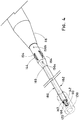
FIG. 1 depicts one example of a deployment device for deploying an endoluminal prosthesis. -
FIG. 2 depicts the deployment device ofFIG. 1 with a sheath retracted to expose an endoluminal prosthesis loaded on the deployment device. -
FIG. 3 depicts one example of a trigger wire guide. -
FIG. 4 depicts another example of a trigger wire guide. -
FIG. 5 is a partial longitudinal cross sectional view of the deployment device ofFIG. 1 and a prosthesis restrained by an axial trigger wire. -
FIG. 6 depicts one example of a stent. -
FIG. 7 depicts the stent ofFIG. 6 with a proximal end of the stent partially restrained by a plurality of conventional axial trigger wires. -
FIG. 8 is a partial longitudinal cross sectional view of the engagement between a conventional axial trigger wire and the stent as shown inFIG. 7 . -
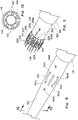
FIG. 9 depicts an intermediate portion of one embodiment of a deployment device with axial trigger wires loaded therein. -
FIG. 10 is a transverse cross sectional view of the deployment device taken along line 10-10 ofFIG. 9 . -
FIG. 11 depicts an intermediate portion of the deployment device ofFIG. 9 with a prosthesis restrained by a circumferential trigger wire. -
FIG. 12 is a partial longitudinal cross sectional view of the engagement between an axial trigger wire, a circumferential trigger wire, and a prosthesis as shown inFIG. 11 . - The specific disclosure which follows relates to apparatus and methods for deploying endoluminal prostheses in body vessels to treat various medical conditions.
- In the present disclosure, the term "proximal" refers to a direction that is generally closest to the heart during a medical procedure, while the term "distal" refers to a direction that is farthest from the heart during a medical procedure.
-
FIGS. 1-2 show one embodiment of adeployment device 100 for deploying anendoluminal prosthesis 200. Thedeployment device 100 may include aguide wire catheter 110. Theguide wire catheter 110 may be configured as an elongate tubular member having adistal end 112, aproximal end 114, and a lumen extending longitudinally between the distal and proximal ends of the guide wire catheter. In use, thedistal end 112 may be adapted to remain outside of the body of the patient while theproximal end 114 may be adapted for insertion into a body vessel within the body of the patient. To that end, anose cone dilator 116 may be positioned at theproximal end 114 of theguide wire catheter 110. Thenose cone dilator 116 may be configured as an elongate tapered extension to aid in advancing the proximal end of thedeployment device 100 within the body vessel. Thenose cone dilator 116 may include a lumen configured to receive a guide wire. Theguide wire catheter 110 may include a connector 117 (e.g., a Luer Lock hub) disposed at thedistal end 112 of the guide wire catheter. Theconnector 117 may be configured to enable the introduction of liquids (e.g., contrast media or therapeutic agents) during a deployment procedure. In one example, an angiographic contrast fluid may be introduced into theconnector 117. The contrast fluid may travel through theguide wire catheter 110 to thenose cone dilator 116 where the contrast fluid may be ejected from one ormore side ports 115 in the nose cone dilator. - A
pusher catheter 120 may surround at least a portion of theguide wire catheter 110. Thepusher catheter 120 may be configured as an elongate tubular member having adistal end 122, aproximal end 124, and a lumen extending longitudinally between the distal and proximal ends of the pusher catheter. Theguide wire catheter 110 may be movable longitudinally and/or rotationally with respect to thepusher catheter 120. In one example, theguide wire catheter 110 may be moved proximally or distally within thepusher catheter 120 to move thenose cone dilator 116 relative to the pusher catheter. Apin vise 119 may be positioned near thedistal end 112 of theguide wire catheter 110 and configured to lock the guide wire catheter in place relative to thepusher catheter 120. - A
sheath 130 may surround at least a portion of thepusher catheter 120. Thesheath 130 may be configured as an elongate tubular member having adistal end 132, aproximal end 134, and a lumen extending longitudinally between the distal and proximal ends of the sheath. Asheath hub 136 may be positioned at thedistal end 132 of thesheath 130. Thesheath hub 136 may include aside tube 138. Theside tube 138 may include a connector (not shown) configured to enable the introduction of liquids between thesheath 130 and thepusher catheter 120. - A
recess 118 may be formed between thenose cone dilator 116 and theproximal end 124 of thepusher catheter 120 as shown inFIGS. 1-2 . In other embodiments, a portion of thepusher catheter 120 may be configured as a trigger wire guide as further described below. In these embodiments, therecess 118 may surround a segment of thepusher catheter 120 having a smaller diameter than the remainder of the pusher catheter. Theprosthesis 200 may be received in therecess 118 for delivery to a desired location within a body vessel. Theprosthesis 200 may be restrained in a compressed delivery configuration within the lumen of thesheath 130. Upon retraction of thesheath 130 to expose theprosthesis 200, the prosthesis may at least partially expand to an expanded configuration. A portion of theprosthesis 200 may be restrained in the compressed configuration even after retraction of thesheath 130. For example, aproximal end 202 of theprosthesis 200 may be restrained in the compressed configuration by a trigger wire system as further described below. - The
deployment device 100 may include a trigger wire system configured to restrain at least a portion of theprosthesis 200 in the compressed configuration. The trigger wire system may include one or moreaxial trigger wires 142 extending generally longitudinally along at least a portion of the length of thedeployment device 100. In one example, the trigger wire system may include four axial trigger wires as shown inFIGS. 1-4 . In another example, the trigger wire system may include six axial trigger wires as shown inFIGS. 9-11 . In other examples, the trigger wire system may include any number of axial trigger wires, as long as the resulting embodiment falls within the scope of the appended claims. Theaxial trigger wires 142 may be attached to an axial triggerwire release mechanism 121, which may be positioned near thedistal end 122 of thepusher catheter 120. Theaxial trigger wires 142 may extend proximally through thedeployment device 100 in the annular space between thepusher catheter 120 and theguide wire catheter 110. Theaxial trigger wires 142 may exit theproximal end 124 of the pusher catheter and extend into therecess 118. Theaxial trigger wires 142 may engage theprosthesis 200 to restrain at least a portion of the prosthesis in the compressed configuration as further described below. Alternatively, or additionally, theaxial trigger wires 142 may engage acircumferential trigger wire 146 also as further described below. The proximal end of each axial trigger wire may be releasably received within thenose cone dilator 116 and/or theguide wire catheter 110 to maintain tension on the axial trigger wire to restrain theprosthesis 200. Thenose cone dilator 116 and/or theguide wire catheter 110 may frictionally engage the received proximal end of theaxial trigger wire 142 to maintain tension on the axial trigger wire. Alternatively, or additionally, the proximal end of theaxial trigger wire 142 may be releasably attached to thenose cone dilator 116 and/or theguide wire catheter 110 by any suitable means including, for example, an adhesive or a mechanical attachment mechanism. - The trigger wire system includes a circumferential trigger wire 146 (see
FIGS. 11-12 ) extending generally longitudinally along at least a portion of the length of thedeployment device 100. Thecircumferential trigger wire 146 may be attached to a circumferential triggerwire release mechanism 123, which may be positioned near thedistal end 122 of thepusher catheter 120. In one example, the circumferential triggerwire release mechanism 123 may be positioned just distal of the axial triggerwire release mechanism 121 as shown inFIGS. 1-2 . A distal portion of thecircumferential trigger wire 146 may extend proximally through thedeployment device 100 in the annular space between thepusher catheter 120 and theguide wire catheter 110. Thecircumferential trigger wire 146 may exit theproximal end 124 of the pusher catheter and extend into therecess 118. A proximal portion of thecircumferential trigger wire 146 may engage theprosthesis 200 to restrain at least a portion of the prosthesis in the compressed configuration as further described below. The proximal end of thecircumferential trigger wire 146 may be releasably received within thenose cone dilator 116 and/or theguide wire catheter 110 to maintain tension on the circumferential trigger wire to restrain theprosthesis 200. Thenose cone dilator 116 and/or theguide wire catheter 110 may frictionally engage the received proximal end of thecircumferential trigger wire 146 to maintain tension on the circumferential trigger wire. Alternatively, or additionally, the proximal end of thecircumferential trigger wire 146 may be releasably attached to thenose cone dilator 116 and/or theguide wire catheter 110 by any suitable means including, for example, an adhesive or a mechanical attachment mechanism. - The
deployment device 100 may include an elongate member such as, for example, atrigger wire guide 150 as shown inFIG. 3 . Thetrigger wire guide 150 may surround a portion of theguide wire catheter 110 near thenose cone dilator 116. Inside therecess 118, theaxial trigger wires 142 may enter a distal end of thetrigger wire guide 150. Thetrigger wire guide 150 may have any suitable configuration including, for example, those described inU.S. Patent No. 7,803,177 to Hartley et al. In the example shown inFIG. 3 , thetrigger wire guide 150 may be configured as a tubular member surrounding at least a portion of theguide wire catheter 110. Thetrigger wire guide 150 may include one or moretrigger wire lumens 152 extending longitudinally within the trigger wire guide. Thetrigger wire guide 150 may include one or moreelongate apertures 154. Eachelongate aperture 154 may extend through the outer wall of thetrigger wire guide 150 to the correspondingtrigger wire lumen 152. For example, thetrigger wire guide 150 may include fourtrigger wire lumens 152 as shown inFIG. 3 . Anaxial trigger wire 142 may be received within eachtrigger wire lumen 152. Eachaxial trigger wire 142 may extend proximally within thetrigger wire lumen 152 to the correspondingelongate aperture 154. - An engagement member may be coupled to the elongate member and may extend outwardly from the elongate member. For example, at the
elongate aperture 154, theaxial trigger wire 142 may exit thetrigger wire guide 150, extend further proximally, and reenter the trigger wire guide through the elongate aperture. In this manner, the portion of theaxial trigger wire 142 external of thetrigger wire guide 150 may form an engagement member configured as acurve 144. Thecurve 144 may be coupled to thetrigger wire guide 150 by the engagement of theaxial trigger wire 142 with theelongate aperture 154. Thecurve 144 may be configured to engage theprosthesis 200 and/or thecircumferential trigger wire 146 as further described below. - Although the engagement member is generally described herein as the
curve 144 formed by theaxial trigger wire 142, the disclosure is not so limited. In other examples, an engagement member may be positioned near thenose cone dilator 116 to engage thecircumferential trigger wire 146 as further described below. For example, opposite ends of a wire segment may be attached to thetrigger wire guide 150, and an intermediate portion of the wire segment may form the engagement member. In this example, the wire segment may not be received within thetrigger wire guide 150. Additionally, or alternatively, the wire segment may not extend to the distal end of the deployment device as described herein with reference to theaxial trigger wire 142. In another example, a protrusion (e.g., a loop or eyelet) may extend from thetrigger wire guide 150 to form the engagement member. The protrusion may be formed separately from or integrally with thetrigger wire guide 150. The protrusion may include an opening to engage thecircumferential trigger wire 146 as further described below. Such alterations are contemplated by and within the scope of this disclosure. - In any of the examples described herein, the trigger wire guide may include a pair of
openings elongate aperture 154 as described below with reference toFIGS. 9-12 . In any of the examples described herein, an annular space may be formed between thetrigger wire guide 150 and theguide wire catheter 110. Thetrigger wire lumens 152 may be omitted, and theaxial guide wires 142 and/or thecircumferential guide wire 146 may be received within the annular space, also as described below with reference toFIGS. 9-12 . Such alternative embodiments are within the scope of this disclosure. -
FIG. 4 shows an alternative example of atrigger wire guide 160. In any of the examples described herein, the trigger wire guide 160 (or various features thereof) may be used in place of or in addition to thetrigger wire guide 150. In this example, thetrigger wire guide 160 may include atubular guide portion 162 and anenlarged engagement portion 164. Thetrigger wire guide 160 may surround theguide wire catheter 110 as described above with reference to thetrigger wire guide 150. Adistal end 163 of thetubular guide portion 162 may be positioned near theproximal end 124 of thepusher catheter 120. In one example, thedistal end 163 of thetubular guide portion 162 may be received within the lumen of thepusher catheter 120. In another example, thetrigger wire guide 160 and thepusher catheter 120 may be formed as a unitary tubular structure, and thetubular guide portion 162 may extend from theproximal end 124 of the pusher catheter. Positioning thedistal end 163 of thetrigger wire guide 160 near theproximal end 124 of thepusher catheter 120 may reduce the length of theaxial trigger wires 142 and/or thecircumferential trigger wire 146 that may be exposed within therecess 118 of thedeployment device 100. This may reduce the potential for snagging or catching a trigger wire on a portion of theprosthesis 200 or thedeployment device 100 during deployment of the prosthesis. - The
enlarged engagement portion 164 of thetrigger wire guide 160 may extend proximally from aproximal end 165 of thetubular guide portion 162. Theenlarged engagement portion 164 may extend to thenose cone dilator 116. Thetubular guide portion 162 may have a diameter that is smaller than the diameter of theenlarged engagement portion 164. The smaller diametertubular guide portion 162 may span a majority of the length of therecess 118 so that theprosthesis 200 may be compressed around the tubular guide portion for delivery. Theenlarged engagement portion 164 may be configured to engage theproximal end 202 of theprosthesis 200 as further described below. - An
annular space 166 may be formed between theguide wire catheter 110 and thetrigger wire guide 160. Theaxial trigger wires 142 and thecircumferential trigger wire 146 may extend longitudinally along thedeployment device 100 within theannular space 166. Theenlarged engagement portion 164 of thetrigger wire guide 160 may include one or moreelongate apertures 154. Theelongate apertures 154 may be configured generally as described above with reference to thetrigger wire guide 150. Eachelongate aperture 154 may be in communication with theannular space 166 between theguide wire catheter 110 and thetrigger wire guide 160. Theaxial trigger wires 142 may pass through theelongate apertures 154 to form thecurves 144 to engage theprosthesis 200 and/or thecircumferential trigger wire 146. Thecircumferential trigger wire 146 may pass through circumferential trigger wire openings in thetrigger wire guide 160 to engage theprosthesis 200 as further described below. -
FIG. 5 is a longitudinal cross sectional view of a proximal portion of theprosthesis 200 loaded on thedeployment device 100. In the view shown inFIG. 5 , thesheath 130 has been retracted to enable partial expansion of theprosthesis 200. Theproximal end 202 of theprosthesis 200 may be restrained in the compressed configuration by the trigger wire system. For example, theaxial trigger wire 142 may extend through theaperture 154 of thetrigger wire guide 150 to form thecurve 144 as described above. Thecurve 144 of theaxial trigger wire 142 may engage aproximal stent 210 of theprosthesis 200. To that end, theaxial trigger wire 142 may pass through abend 212 interconnecting twoadjacent struts 214 of theproximal stent 210. Theaxial trigger wire 142 may restrain the engagedbend 212 of theproximal stent 210 in close proximity to thetrigger wire guide 150. Multipleaxial trigger wires 142 may engagemultiple bends 212 of theproximal stent 210 to restrain each engaged bend of the proximal stent in close proximity to thetrigger wire guide 150. In this manner, theproximal end 202 of theprosthesis 210 may be restrained in the compressed configuration. - When the
proximal stent 210 is compressed for delivery (e.g., when theprosthesis 200 is compressed within the sheath 130), theaxial trigger wire 142 disposed through thebend 212 as shown inFIG. 5 may become pinched between thestruts 214 of the stent. This may damage thestent 210 and/or theaxial trigger wire 142. Thus, it may be beneficial for the axial trigger wires to engage the proximal stent of the prosthesis at locations other than the bends between adjacent struts of the stent. -
U.S. Patent Application Pub. No. 2009/0204202 by Dierking et al. , describes stent designs which may be deployed using thedeployment device 100 described herein. For example,FIG. 6 shows an alternative example of aproximal stent 220. Theprosthesis 200 may include theproximal stent 220 as opposed to theproximal stent 210 described above. In another example, thestent 210 may be modified to include one or more of the features of the stent 220 (e.g., the end regions 226) described below. Theproximal stent 220 may include one or more first proximal apices 221a. Each firstproximal apex 221a may include anend region 226 having anaperture 227 formed therein. Theaperture 227 may be configured to receive anaxial trigger wire 142 as further described below. Theend region 226 may be positioned proximal of thebend 222 between twoadjacent struts 224 of thestent 220 so that, upon compression of theprosthesis 200, theaxial trigger wire 142 may not be pinched between the adjacent struts of theproximal stent 220. In other words, theend region 226 may be configured as an eyelet extending proximally from thebend 222 between twoadjacent struts 224 to receive anaxial trigger wire 142. The eyelet may remain open even after compression of thestent 220. - Additionally, or alternatively, the
proximal stent 220 may include one or more secondproximal apices 221b. Each secondproximal apex 221b may include anend region 228 having anintegral barb 229 formed therein. Thebarb 229 may be configured to engage a wall of a body vessel upon implantation of theprosthesis 200 to prevent migration of the prosthesis within the body vessel. Theproximal stent 220 may include alternating first proximal apices and second proximal apices, as shown inFIG. 6 , so that every other apex may be engaged by a trigger wire. In other examples, theproximal stent 220 may have any number of first proximal apices and second proximal apices. In one example, each apex of the firstproximal stent 220 may be configured as a first proximal apex (i.e., each apex may include anend region 226 with an aperture 227). -
FIG. 7 shows theproximal stent 220, with the proximal end of the proximal stent restrained in the partly compressed configuration by a conventional trigger wire system.FIG. 8 shows a partial longitudinal cross sectional view of one of the firstproximal apices 221a engaged by anaxial trigger wire 142 as shown inFIG. 7 . Theaxial trigger wire 142 may exit thetrigger wire guide 150 through theelongate aperture 154 as described above. Theaxial trigger wire 142 may pass through theaperture 227 of theproximal stent 220 of theprosthesis 200 and then reenter thetrigger wire guide 150 through theelongate aperture 154. In this manner, thecurve 144 of theaxial trigger wire 142 may engage theend region 226 of theproximal stent 220 to restrain the end region in close proximity to thetrigger wire guide 150. - One advantage of the trigger wire system shown in
FIGS. 7-8 is that theaxial trigger wires 142 may be disposed through theapertures 227 of the firstproximal apices 221a as opposed to being disposed through thebends 222 of theproximal stent 220. This may reduce the probability that theaxial trigger wires 142 and/or thestruts 224 of theproximal stent 220 may become damaged upon compression of theprosthesis 200. In other words, because theapertures 227 may not be pinched closed upon compression of theprosthesis 200, pinching of theaxial trigger wires 142 may be avoided. - As shown in
FIG. 7 , each of the first proximal apices 221a of theproximal stent 220 may be engaged by anaxial trigger wire 142, while each of the secondproximal apices 221b may remain unengaged by the axial trigger wires. Restraining the firstproximal apices 221a in close proximity to thetrigger wire guide 150 may indirectly restrain the adjacent secondproximal apices 221b in a position that is closer to the trigger wire guide than in the expanded configuration. However, the secondproximal apices 221b may remain farther from thetrigger wire guide 150 than the firstproximal apices 221a as shown inFIG. 7 . - In embodiments, the trigger wire system includes a circumferential trigger wire in addition to the axial trigger wires. The proximal portion of the circumferential trigger wire may extend at least partially circumferentially around the proximal stent of the prosthesis to restrain the proximal end of the prosthesis in the compressed configuration as further described below.
-
FIGS. 9-11 show an intermediate portion of one embodiment of thedeployment device 100 having acircumferential trigger wire 146. Thedeployment device 100 may include theguide wire catheter 110 and thetrigger wire guide 150 generally as described above with reference toFIGS. 1-5 .FIG. 10 is a cross sectional view taken along line 10-10 ofFIG. 9 . At least oneaxial trigger wire 142 may extend longitudinally within the annular space between theguide wire catheter 110 and thetrigger wire guide 150. For example, sixaxial trigger wires 142 may extend longitudinally within thetrigger wire guide 150 as shown inFIGS. 9-10 . Additionally, or alternatively, the distal portion of thecircumferential trigger wire 146 may extend longitudinally within thetrigger wire guide 150. - In this embodiment, the
trigger wire guide 150 may include at least one pair of openings in place of the at least oneelongate aperture 154. For example, thetrigger wire guide 150 may include six pairs of openings as shown inFIGS. 9-11 . Each pair of openings may include afirst opening 154a and asecond opening 154b. The first andsecond openings trigger wire guide 150. Thesecond opening 154b may be positioned longitudinally proximal of thefirst opening 154a. Anaxial trigger wire 142 may exit thetrigger wire guide 150 through thefirst opening 154a, extend proximally external of the trigger wire guide, and reenter the trigger wire guide through thesecond opening 154b. In this manner, thecurve 144 may be formed external of thetrigger wire guide 150. Eachaxial trigger wire 142 may extend through a corresponding pair of openings. The pairs of openings may be aligned with one another with respect to the longitudinal axis of the trigger wire guide150 and spaced from one another circumferentially around the trigger wire guide. Although thedeployment device 100 shown inFIGS. 9-11 may include six axial trigger wires extending through six pairs of openings, any number of axial trigger wires (e.g., four axial trigger wires as described above with reference toFIGS. 3-5 ) extending through any number of pairs of openings may be used. Additionally, or alternatively, one or more elongate apertures may be used in place of one or more of the pairs of openings as described above with reference toFIGS. 3-5 . - The
trigger wire guide 150 may include a pair of circumferential trigger wire openings. The pair of circumferential trigger wire openings may include a first circumferentialtrigger wire opening 156a and a second circumferentialtrigger wire opening 156b. The first and second circumferentialtrigger wire openings trigger wire guide 150. The second circumferentialtrigger wire opening 156b may be positioned longitudinally proximal of the first circumferentialtrigger wire opening 156a. The first circumferentialtrigger wire opening 156a may be positioned longitudinally distal of thefirst openings 154a, and the second circumferentialtrigger wire opening 156b may be positioned longitudinally proximal of thesecond openings 154b. Thecircumferential trigger wire 146 may exit thetrigger wire guide 150 through the first circumferentialtrigger wire opening 156a, extend proximally and at least partially circumferentially around the trigger wire guide external of the trigger wire guide, and reenter the trigger wire guide through the second circumferentialtrigger wire opening 156b as shown inFIG. 11 and further described below. -
FIG. 11 shows a proximal portion of theprosthesis 200 loaded on thedeployment device 100. Theprosthesis 200 may include a series of firstproximal apices 221a and a series of secondproximal apices 221b as described above with reference toFIGS. 6-7 . Each pair ofopenings trigger wire guide 150 may be generally aligned with acorresponding aperture 227 of theproximal stent 220 of theprosthesis 200. The first andsecond openings aperture 227. For example, thefirst opening 154a may be generally aligned with a distal end of theaperture 227 while thesecond opening 154b may be generally aligned with a proximal end of theaperture 227. Theaxial trigger wire 142 may be disposed within theopenings curve 144 extends through theaperture 227. In this example, thecurve 144 may be aligned with theaperture 227 as opposed to engaging theend region 226 as described above. In other words, theend region 226 may not be disposed between thecurve 144 and thetrigger wire guide 150 as described above, but rather thecurve 144 may be received within theaperture 227 of theproximal stent 220. Thecurve 144 of eachaxial trigger wire 142 may be disposed within the correspondingaperture 227 of theproximal stent 220 of theprosthesis 200 as shown inFIG. 11 . In another embodiment, thecurve 144 may be disposed within any void near the proximal end of theproximal stent 220. For example, thecurve 144 may be disposed within the void between two adjacent struts of theproximal stent 220. - The first circumferential
trigger wire opening 156a may be generally aligned with a void of theproximal stent 220 so that the first circumferential trigger wire opening may be accessible through the proximal stent. For example, the first circumferentialtrigger wire opening 156a may be aligned with the void between two adjacent struts of theproximal stent 220. Thecircumferential trigger wire 146 may exit the first circumferentialtrigger wire opening 156a and pass through the void in theproximal stent 220. Thecircumferential trigger wire 146 may extend proximally and circumferentially to engage theproximal stent 220. For example, thecircumferential trigger wire 146 may extend through thecurve 144 of at least one of theaxial trigger wires 142.FIG. 12 shows a partial longitudinal cross sectional view of one of the firstproximal apices 221a engaged by acircumferential trigger wire 146 as shown inFIG. 11 . Thecircumferential trigger wire 146 is received within thecurve 144 and between theaxial trigger wire 142 and theproximal stent 220 as shown inFIGS. 11-12 . Theaxial trigger wire 142 may engage thecircumferential trigger wire 146 to retain the circumferential trigger wire in close proximity to theproximal stent 220 and thetrigger wire guide 150. In other words, theaxial trigger wire 142 may prevent thecircumferential trigger wire 146 from moving radially away from thetrigger wire guide 150. Theaxial trigger wire 142 also may retain thecircumferential trigger wire 146 longitudinally between the distal end of theaperture 227 and the proximal end of the aperture. This may prevent thecircumferential trigger wire 146 from moving proximally, and potentially slipping off of the proximal end of theproximal stent 220, or moving distally, and potentially allowing expansion of the proximal end of the proximal stent. In this manner, theproximal stent 220 may be restrained between thecircumferential trigger wire 146 and thetrigger wire guide 150 and in close proximity to thetrigger wire guide 150. - The
circumferential trigger wire 146 extends circumferentially around at least a portion of theproximal stent 220 and thetrigger wire guide 150 as shown inFIG. 11 . Thecircumferential trigger wire 146 is received within thecurve 144 of each of theaxial trigger wires 142 around the circumference of theproximal stent 220. In this manner, thecircumferential trigger wire 146 at least partially encircles an outer surface of theproximal stent 220 to restrain the proximal stent in close proximity to the trigger wire guide 150 (e.g., in the compressed configuration). Thecircumferential trigger wire 146 may extend proximally and reenter thetrigger wire guide 150 through the second circumferentialtrigger wire opening 156b. The proximal end of thecircumferential trigger wire 146 may be received within thenose cone dilator 116 to maintain tension on the circumferential trigger wire. - A trigger wire system having a circumferential trigger wire may be beneficial for multiple reasons. For example, the
circumferential trigger wire 146 may extend circumferentially around theproximal stent 220 to engage each of the proximal apices. In other words, thecircumferential trigger wire 146 may engage the firstproximal apices 221a having theapertures 227 and the secondproximal apices 221b having thebarbs 229. Thus, the circumferential trigger wire may restrain each proximal apex of theproximal stent 220 in close proximity to thetrigger wire guide 150. In this manner, thecircumferential trigger wire 146 may restrain the proximal end of theproximal stent 220 in the compressed configuration. - Because the
proximal stent 220 is engaged by a single circumferential trigger wire 146 (which itself may be engaged by the axial trigger wires 142), the proximal end of theprosthesis 200 is released by retracting the single circumferential trigger wire as opposed to multipleaxial trigger wires 142. This may reduce the retraction force required to release the proximal end of theprosthesis 200. Such a reduced retraction force may provide a desirable tactile feel for a physician during deployment of theprosthesis 200 to aid in precise placement of the prosthesis within a body vessel. The ability to release the proximal end of theprosthesis 200 by retracting a single trigger wire may reduce the probability of the trigger wire becoming tangled (e.g., with other trigger wires) during deployment of the prosthesis. - The addition of the
circumferential trigger wire 146 to the trigger wire system also may provide a safety factor to thedeployment device 100. For example, it may become difficult or even impossible to retract thecircumferential trigger wire 146 from engagement with theaxial trigger wires 142. This may be caused by thecircumferential trigger wire 146 snagging on a component of theprosthesis 200 or thedelivery device 100 or breakage of the circumferential trigger wire. In such a situation, theaxial trigger wires 142 may be retracted to release the circumferential trigger wire from engagement with theproximal stent 220. In other words, theproximal stent 220 may be released by retracting either thecircumferential trigger wire 146 or theaxial trigger wires 142. Providing alternative means of releasing theproximal stent 220 may enhance the safety of thedeployment device 100. - The
prosthesis 200 may be positioned within a body vessel of a patient using conventional endovascular techniques. Once theprosthesis 200 is in the desired location within the body vessel, thesheath 130 may be retracted to enable partial expansion of theprosthesis 200 as shown inFIG. 2 . Theproximal end 202 of theprosthesis 200 is restrained in the compressed configuration by thecircumferential trigger wire 146 as shown inFIG. 11 . In this partially expanded configuration, theprosthesis 200 may be repositioned (e.g., rotated and/or translated) within the body vessel. Once theprosthesis 200 is positioned as desired, theproximal end 202 of the prosthesis may be released to enable expansion of the prosthesis to the expanded configuration. - The
proximal end 202 of the prosthesis may be released by manipulation of the trigger wire release mechanisms. For example, the circumferential triggerwire release mechanism 123 may be unlocked and retracted distally relative to theguide wire catheter 110. Initial retraction of the circumferential triggerwire release mechanism 123 may pull the proximal end of thecircumferential trigger wire 146 out of engagement with thenose cone dilator 116. Further retraction of the circumferential triggerwire release mechanism 123 may cause thecircumferential trigger wire 146 to slide out of engagement with each of theaxial trigger wires 142. Upon disengagement of thecircumferential trigger wire 146 from theaxial trigger wires 142, theproximal stent 220 of theprosthesis 200 is not restrained by the circumferential trigger wire, and the proximal stent expands to the expanded configuration. The circumferential triggerwire release mechanism 123 may be further retracted to remove thecircumferential trigger wire 146 from thedeployment device 100. - After removal of the
circumferential trigger wire 146 from thedeployment device 100, theaxial trigger wires 142 may remain loaded in thedeployment device 100 during retraction of the deployment device from the body of the patient. In other embodiments, the axial trigger wires may be removed from thedeployment device 100 prior to retraction of the deployment device. For example, the axial triggerwire release mechanism 121 may be unlocked and retracted distally relative to theguide wire catheter 110. Initial retraction of the axial triggerwire release mechanism 121 may pull the proximal ends of theaxial trigger wires 142 out of engagement with thenose cone dilator 116. The axial triggerwire release mechanism 121 may be further retracted to slide theaxial trigger wires 142 out of theopenings trigger wire guide 150 and to remove the axial trigger wires from thedeployment device 100. Removing theaxial trigger wires 142 from thedeployment device 100 prior to retraction of the deployment device from the body of the patient may reduce the probability of catching or snagging any of the axial trigger wires on theprosthesis 200 during retraction of the deployment device. - Although the trigger wire system has been described as engaging the proximal end of the prosthesis to restrain the proximal end in the compressed configuration, the trigger wire system may engage the distal end or any other portion of the prosthesis in a similar manner to restrain the distal end or other portion of the prosthesis in the compressed configuration. In one example, one trigger wire system may engage the proximal stent of the prosthesis while another trigger wire system may engage a distal stent of the prosthesis. Alternatively, or additionally, multiple trigger wire systems may engage any portion of the prosthesis (e.g., any stent of the prosthesis) to restrain that portion in the compressed configuration, as long as the resulting embodiment falls within the scope of the appended claims.
- While various embodiments of the invention have been described, the invention is not to be restricted except by the scope of the attached claims. Moreover, the advantages described herein are not necessarily the only advantages of the invention and it is not necessarily expected that every embodiment of the invention will achieve all of the advantages described.
Claims (3)
- A system including:a deployment device including a tubular trigger wire guide, a plurality of axial trigger wire apertures (154) in the trigger wire guide, and at least one circumferential trigger wire aperture (156) in the trigger wire guide;an expandable endoluminal prosthesis positioned on the deployment device;a plurality of axial trigger wires (142) received within the trigger wire guide, each axial trigger wire (142) extending through a corresponding one of the plurality of axial trigger wire apertures (154) and exiting the trigger wire guide; anda circumferential trigger wire received within the trigger wire guide, the circumferential trigger wire extending through the circumferential trigger wire aperture (156) and a single circumferential trigger wire loop exiting the trigger wire guide and at least partially encircling the prosthesis, the circumferential trigger wire engaged by the plurality of axial trigger wires (142) and restraining at least a portion of the prosthesis in a compressed configuration;wherein each axial trigger wire (142) exits the trigger wire guide at a first longitudinal position and reenters the trigger wire guide at a second longitudinal position proximal of the first longitudinal position, a portion of the axial trigger wire (142) disposed external of the trigger wire guide including a curve (144), wherein a portion of the circumferential trigger wire disposed external of the trigger wire guide extends at least partially circumferentially around the prosthesis and is received between the curve (144) of each of the plurality of axial trigger wires and an outer surface of the prosthesis.
- A system according to claim 1, wherein the prosthesis further includes a stent comprising a plurality of end regions each including an aperture, and each aperture of the stent is aligned with a corresponding one of the plurality of axial trigger wire apertures (154).
- A system according to claim 2, wherein the curve (144) of each of the plurality of axial trigger wires (142) is received within the corresponding one of the plurality of apertures of the stent.
Applications Claiming Priority (1)
| Application Number | Priority Date | Filing Date | Title |
|---|---|---|---|
| US201161570439P | 2011-12-14 | 2011-12-14 |
Publications (2)
| Publication Number | Publication Date |
|---|---|
| EP2604232A1 EP2604232A1 (en) | 2013-06-19 |
| EP2604232B1 true EP2604232B1 (en) | 2021-02-24 |
Family
ID=47602913
Family Applications (1)
| Application Number | Title | Priority Date | Filing Date |
|---|---|---|---|
| EP12197088.3A Active EP2604232B1 (en) | 2011-12-14 | 2012-12-13 | Circumferential trigger wire for deploying an endoluminal prosthesis |
Country Status (2)
| Country | Link |
|---|---|
| US (3) | US9278018B2 (en) |
| EP (1) | EP2604232B1 (en) |
Families Citing this family (27)
| Publication number | Priority date | Publication date | Assignee | Title |
|---|---|---|---|---|
| EP2506810B1 (en) | 2009-11-30 | 2020-07-08 | Endospan Ltd | Multi-component stent-graft system for implantation in a blood vessel with multiple branches |
| CA2783554C (en) | 2009-12-08 | 2016-02-16 | Endospan Ltd. | Endovascular stent-graft system with fenestrated and crossing stent-grafts |
| WO2012104842A2 (en) | 2011-02-03 | 2012-08-09 | Endospan Ltd. | Implantable medical devices constructed of shape memory material |
| US9254209B2 (en) | 2011-07-07 | 2016-02-09 | Endospan Ltd. | Stent fixation with reduced plastic deformation |
| EP2604232B1 (en) * | 2011-12-14 | 2021-02-24 | Cook Medical Technologies LLC | Circumferential trigger wire for deploying an endoluminal prosthesis |
| CN105208969B (en) | 2013-03-11 | 2017-10-20 | 恩多斯潘有限公司 | Multicomponent stent-graft system for aortic dissection |
| US10603197B2 (en) * | 2013-11-19 | 2020-03-31 | Endospan Ltd. | Stent system with radial-expansion locking |
| US20170172461A1 (en) * | 2014-03-31 | 2017-06-22 | Spiration, Inc. D.B.A. Olympus Respiratory America | Endoluminal sizing device |
| BR112017012425A2 (en) | 2014-12-18 | 2018-01-02 | Endospan Ltd | endovascular stent graft with fatigue resistant lateral tube |
| US10016293B2 (en) | 2014-12-29 | 2018-07-10 | Cook Medical Technologies Llc | Prosthesis delivery systems having an atraumatic tip for use with trigger wires |
| US10092428B2 (en) * | 2014-12-30 | 2018-10-09 | Cook Medical Technologies Llc | Low profile prosthesis delivery device |
| CN106913408B (en) * | 2015-12-28 | 2018-10-26 | 先健科技(深圳)有限公司 | Transport system and intraluminal stent system |
| CN110167492B (en) | 2016-11-09 | 2021-10-12 | 波士顿科学国际有限公司 | Stent anchoring system |
| EP3932373B1 (en) | 2017-02-24 | 2022-12-21 | Bolton Medical, Inc. | Delivery system for radially constricting a stent graft |
| WO2018156842A1 (en) | 2017-02-24 | 2018-08-30 | Bolton Medical, Inc. | System and method to radially constrict a stent graft |
| EP3534838B1 (en) | 2017-02-24 | 2021-01-27 | Bolton Medical, Inc. | Radially adjustable stent graft delivery system |
| US10709541B2 (en) | 2017-04-28 | 2020-07-14 | Cook Medical Technologies Llc | Systems and methods for adjusting the diameter of an endoluminal prosthesis and an endoluminal prosthesis configured for the same |
| EP3638150B1 (en) * | 2017-06-16 | 2024-10-09 | Boston Scientific Scimed, Inc. | Stent and sleeve deployment |
| US10641427B2 (en) | 2018-04-03 | 2020-05-05 | Mueller International, Llc | Stents and methods for repairing pipes |
| WO2020172136A1 (en) | 2019-02-19 | 2020-08-27 | Mueller International, Llc | Stent springs and stents for repairing pipes |
| US11079058B2 (en) | 2019-03-15 | 2021-08-03 | Mueller International , LLC | Stent with coiled spring |
| US11187366B2 (en) | 2019-03-15 | 2021-11-30 | Mueller International, Llc | Stent for repairing a pipe |
| US11326731B2 (en) | 2019-04-24 | 2022-05-10 | Mueller International, Llc | Pipe repair assembly |
| US11802646B2 (en) | 2019-08-09 | 2023-10-31 | Mueller International, Llc | Pipe repair device |
| US11391405B2 (en) | 2019-08-09 | 2022-07-19 | Mueller International, Llc | Deployment probe for pipe repair device |
| GB2605559B (en) | 2021-01-07 | 2023-04-05 | Cook Medical Technologies Llc | Stent graft |
| AU2021201336B1 (en) | 2021-03-02 | 2021-07-15 | Cook Medical Technologies Llc | A constraint arrangement for a stent-graft loaded onto a delivery system |
Citations (2)
| Publication number | Priority date | Publication date | Assignee | Title |
|---|---|---|---|---|
| WO2010090699A1 (en) * | 2009-01-19 | 2010-08-12 | Gore Enterprise Holdings, Inc. | Forced deployment sequence |
| WO2011081997A1 (en) * | 2009-12-30 | 2011-07-07 | Wilson-Cook Medical Inc. | Proximal release delivery device |
Family Cites Families (37)
| Publication number | Priority date | Publication date | Assignee | Title |
|---|---|---|---|---|
| US570439A (en) | 1896-10-27 | Engine | ||
| US4878906A (en) * | 1986-03-25 | 1989-11-07 | Servetus Partnership | Endoprosthesis for repairing a damaged vessel |
| US4913141A (en) * | 1988-10-25 | 1990-04-03 | Cordis Corporation | Apparatus and method for placement of a stent within a subject vessel |
| US5405378A (en) * | 1992-05-20 | 1995-04-11 | Strecker; Ernst P. | Device with a prosthesis implantable in the body of a patient |
| US5843158A (en) | 1996-01-05 | 1998-12-01 | Medtronic, Inc. | Limited expansion endoluminal prostheses and methods for their use |
| US5830229A (en) * | 1997-03-07 | 1998-11-03 | Micro Therapeutics Inc. | Hoop stent |
| WO2001074270A2 (en) | 2000-03-30 | 2001-10-11 | Teramed Corporation | Bifurcated graft and method of delivery |
| US6562064B1 (en) | 2000-10-27 | 2003-05-13 | Vascular Architects, Inc. | Placement catheter assembly |
| DE10105160B4 (en) | 2001-02-06 | 2005-09-01 | Osypka, Peter, Dr.-Ing. | Implantable vascular support |
| WO2002078569A2 (en) | 2001-03-28 | 2002-10-10 | Cook Incorporated | Modular stent graft assembly and use thereof |
| ATE310559T1 (en) * | 2002-05-29 | 2005-12-15 | Cook William A Australia | TRIGGER WIRE SYSTEM FOR A PROSTHESIS PLACEMENT DEVICE |
| AU2003258337A1 (en) * | 2002-08-23 | 2004-03-11 | Cook Incorporated | Asymmetric stent graft attachment |
| US7611528B2 (en) | 2003-01-24 | 2009-11-03 | Medtronic Vascular, Inc. | Stent-graft delivery system |
| WO2004078065A2 (en) * | 2003-03-03 | 2004-09-16 | Sinus Rhythm Technologies, Inc. | Electrical conduction block implant device |
| WO2005034811A1 (en) * | 2003-10-10 | 2005-04-21 | William Cook Europe Aps | Stent graft retention system |
| EP2204141B1 (en) * | 2003-10-15 | 2013-06-05 | Cook Medical Technologies LLC | Prosthesis deployment system retention device |
| US7635382B2 (en) * | 2003-10-22 | 2009-12-22 | Medtronic Vascular, Inc. | Delivery system for long self-expanding stents |
| US8182528B2 (en) * | 2003-12-23 | 2012-05-22 | Sadra Medical, Inc. | Locking heart valve anchor |
| WO2006007389A1 (en) * | 2004-06-16 | 2006-01-19 | Cook Incorprated | Thoracic deployment device and stent graft |
| AU2005289395B2 (en) | 2004-09-28 | 2010-08-26 | Cook Incorporated | Device for treating aortic dissection |
| FR2894131B1 (en) * | 2005-12-02 | 2008-12-05 | Perouse Soc Par Actions Simpli | DEVICE FOR TREATING A BLOOD VESSEL, AND ASSOCIATED TREATMENT NECESSARY. |
| JP5042244B2 (en) | 2006-02-27 | 2012-10-03 | ウィリアム・エイ・クック・オーストラリア・プロプライエタリー・リミテッド | Combined stent graft introducer and stent graft |
| CN101045022B (en) * | 2006-03-30 | 2010-08-25 | 温宁 | Self-expanding stent axial wire-drawing tensioning mechanism |
| FR2899096B1 (en) * | 2006-04-04 | 2008-12-05 | Perouse Soc Par Actions Simpli | DEVICE FOR TREATING A CIRCULATION CIRCULATION OF THE BLOOD AND METHOD OF PREPARING SAID DEVICE |
| AU2007325652B2 (en) * | 2006-11-30 | 2012-07-12 | Cook Medical Technologies Llc | Implant release mechanism |
| US8226701B2 (en) * | 2007-09-26 | 2012-07-24 | Trivascular, Inc. | Stent and delivery system for deployment thereof |
| WO2009091509A1 (en) * | 2008-01-16 | 2009-07-23 | St. Jude Medical, Inc. | Delivery and retrieval systems for collapsible/expandable prosthetic heart valves |
| US8163007B2 (en) | 2008-02-08 | 2012-04-24 | Cook Medical Technologies Llc | Stent designs for use with one or more trigger wires |
| EP2262444B1 (en) * | 2008-04-09 | 2018-02-28 | Cook Medical Technologies LLC | Stent-graft |
| EP2349124B1 (en) | 2008-09-05 | 2018-10-17 | Cook Medical Technologies LLC | Apparatus for improved stent deployment |
| JP5284165B2 (en) * | 2009-03-31 | 2013-09-11 | テルモ株式会社 | Biological organ lesion improvement device |
| FR2946865B1 (en) * | 2009-06-17 | 2012-08-31 | Perouse Lab | DEVICE FOR TREATING A BLOOD CIRCULATION CONDUIT |
| EP2528553B1 (en) * | 2010-01-29 | 2017-10-18 | Cook Medical Technologies LLC | Mechanically expandable delivery and dilation systems |
| US8523932B2 (en) * | 2010-05-24 | 2013-09-03 | Cook Medical Technologies Llc | Variable diameter trigger wire |
| US8840659B2 (en) * | 2011-04-28 | 2014-09-23 | Cook Medical Technologies Llc | Stent and stent-graft designs |
| EP2604232B1 (en) * | 2011-12-14 | 2021-02-24 | Cook Medical Technologies LLC | Circumferential trigger wire for deploying an endoluminal prosthesis |
| US9402755B2 (en) * | 2012-03-13 | 2016-08-02 | W. L. Gore & Associates, Inc. | Sleeve retraction system |
-
2012
- 2012-12-13 EP EP12197088.3A patent/EP2604232B1/en active Active
- 2012-12-13 US US13/713,517 patent/US9278018B2/en active Active
-
2016
- 2016-03-07 US US15/062,762 patent/US10172731B2/en active Active
-
2018
- 2018-11-30 US US16/205,591 patent/US10905575B2/en active Active
Patent Citations (2)
| Publication number | Priority date | Publication date | Assignee | Title |
|---|---|---|---|---|
| WO2010090699A1 (en) * | 2009-01-19 | 2010-08-12 | Gore Enterprise Holdings, Inc. | Forced deployment sequence |
| WO2011081997A1 (en) * | 2009-12-30 | 2011-07-07 | Wilson-Cook Medical Inc. | Proximal release delivery device |
Also Published As
| Publication number | Publication date |
|---|---|
| EP2604232A1 (en) | 2013-06-19 |
| US20190091051A1 (en) | 2019-03-28 |
| US10905575B2 (en) | 2021-02-02 |
| US10172731B2 (en) | 2019-01-08 |
| US9278018B2 (en) | 2016-03-08 |
| US20130158646A1 (en) | 2013-06-20 |
| US20160184119A1 (en) | 2016-06-30 |
Similar Documents
| Publication | Publication Date | Title |
|---|---|---|
| US10905575B2 (en) | Circumferential trigger wire for deploying an endoluminal prosthesis | |
| US9629733B2 (en) | Stents having barbs protected during delivery | |
| US9364355B2 (en) | Systems and methods for deploying a portion of a stent using at least one coiled member | |
| US10695205B2 (en) | Systems and methods for securing and releasing a portion of a stent | |
| US9144510B2 (en) | Systems and methods for deploying a portion of a stent using at least one coiled member | |
| US9456913B2 (en) | Implant introducer with helical trigger wire | |
| US20140277341A1 (en) | Wireless medical device release mechanism | |
| US9629737B2 (en) | Delivery system for staged stent release | |
| US10639180B2 (en) | Systems and methods for deploying a portion of a stent using an auger-style device | |
| CA2818268C (en) | Systems and methods for deploying a portion of a stent using at least one coiled member | |
| EP2842526A1 (en) | System for deploying at least a portion of a stent | |
| US10016293B2 (en) | Prosthesis delivery systems having an atraumatic tip for use with trigger wires |
Legal Events
| Date | Code | Title | Description |
|---|---|---|---|
| PUAI | Public reference made under article 153(3) epc to a published international application that has entered the european phase |
Free format text: ORIGINAL CODE: 0009012 |
|
| AK | Designated contracting states |
Kind code of ref document: A1 Designated state(s): AL AT BE BG CH CY CZ DE DK EE ES FI FR GB GR HR HU IE IS IT LI LT LU LV MC MK MT NL NO PL PT RO RS SE SI SK SM TR |
|
| AX | Request for extension of the european patent |
Extension state: BA ME |
|
| 17P | Request for examination filed |
Effective date: 20131219 |
|
| RBV | Designated contracting states (corrected) |
Designated state(s): AL AT BE BG CH CY CZ DE DK EE ES FI FR GB GR HR HU IE IS IT LI LT LU LV MC MK MT NL NO PL PT RO RS SE SI SK SM TR |
|
| 17Q | First examination report despatched |
Effective date: 20160318 |
|
| GRAP | Despatch of communication of intention to grant a patent |
Free format text: ORIGINAL CODE: EPIDOSNIGR1 |
|
| INTG | Intention to grant announced |
Effective date: 20160913 |
|
| RAP1 | Party data changed (applicant data changed or rights of an application transferred) |
Owner name: COOK MEDICAL TECHNOLOGIES LLC |
|
| GRAJ | Information related to disapproval of communication of intention to grant by the applicant or resumption of examination proceedings by the epo deleted |
Free format text: ORIGINAL CODE: EPIDOSDIGR1 |
|
| STAA | Information on the status of an ep patent application or granted ep patent |
Free format text: STATUS: EXAMINATION IS IN PROGRESS |
|
| INTC | Intention to grant announced (deleted) | ||
| GRAP | Despatch of communication of intention to grant a patent |
Free format text: ORIGINAL CODE: EPIDOSNIGR1 |
|
| STAA | Information on the status of an ep patent application or granted ep patent |
Free format text: STATUS: GRANT OF PATENT IS INTENDED |
|
| RIN1 | Information on inventor provided before grant (corrected) |
Inventor name: ROEDER, BLAYNE |
|
| INTG | Intention to grant announced |
Effective date: 20200917 |
|
| GRAS | Grant fee paid |
Free format text: ORIGINAL CODE: EPIDOSNIGR3 |
|
| GRAA | (expected) grant |
Free format text: ORIGINAL CODE: 0009210 |
|
| STAA | Information on the status of an ep patent application or granted ep patent |
Free format text: STATUS: THE PATENT HAS BEEN GRANTED |
|
| AK | Designated contracting states |
Kind code of ref document: B1 Designated state(s): AL AT BE BG CH CY CZ DE DK EE ES FI FR GB GR HR HU IE IS IT LI LT LU LV MC MK MT NL NO PL PT RO RS SE SI SK SM TR |
|
| REG | Reference to a national code |
Ref country code: GB Ref legal event code: FG4D |
|
| REG | Reference to a national code |
Ref country code: CH Ref legal event code: EP |
|
| REG | Reference to a national code |
Ref country code: AT Ref legal event code: REF Ref document number: 1363547 Country of ref document: AT Kind code of ref document: T Effective date: 20210315 |
|
| REG | Reference to a national code |
Ref country code: IE Ref legal event code: FG4D |
|
| REG | Reference to a national code |
Ref country code: DE Ref legal event code: R096 Ref document number: 602012074482 Country of ref document: DE |
|
| REG | Reference to a national code |
Ref country code: LT Ref legal event code: MG9D |
|
| REG | Reference to a national code |
Ref country code: NL Ref legal event code: MP Effective date: 20210224 |
|
| PG25 | Lapsed in a contracting state [announced via postgrant information from national office to epo] |
Ref country code: HR Free format text: LAPSE BECAUSE OF FAILURE TO SUBMIT A TRANSLATION OF THE DESCRIPTION OR TO PAY THE FEE WITHIN THE PRESCRIBED TIME-LIMIT Effective date: 20210224 Ref country code: GR Free format text: LAPSE BECAUSE OF FAILURE TO SUBMIT A TRANSLATION OF THE DESCRIPTION OR TO PAY THE FEE WITHIN THE PRESCRIBED TIME-LIMIT Effective date: 20210525 Ref country code: FI Free format text: LAPSE BECAUSE OF FAILURE TO SUBMIT A TRANSLATION OF THE DESCRIPTION OR TO PAY THE FEE WITHIN THE PRESCRIBED TIME-LIMIT Effective date: 20210224 Ref country code: PT Free format text: LAPSE BECAUSE OF FAILURE TO SUBMIT A TRANSLATION OF THE DESCRIPTION OR TO PAY THE FEE WITHIN THE PRESCRIBED TIME-LIMIT Effective date: 20210624 Ref country code: LT Free format text: LAPSE BECAUSE OF FAILURE TO SUBMIT A TRANSLATION OF THE DESCRIPTION OR TO PAY THE FEE WITHIN THE PRESCRIBED TIME-LIMIT Effective date: 20210224 Ref country code: BG Free format text: LAPSE BECAUSE OF FAILURE TO SUBMIT A TRANSLATION OF THE DESCRIPTION OR TO PAY THE FEE WITHIN THE PRESCRIBED TIME-LIMIT Effective date: 20210524 Ref country code: NO Free format text: LAPSE BECAUSE OF FAILURE TO SUBMIT A TRANSLATION OF THE DESCRIPTION OR TO PAY THE FEE WITHIN THE PRESCRIBED TIME-LIMIT Effective date: 20210524 |
|
| REG | Reference to a national code |
Ref country code: AT Ref legal event code: MK05 Ref document number: 1363547 Country of ref document: AT Kind code of ref document: T Effective date: 20210224 |
|
| PG25 | Lapsed in a contracting state [announced via postgrant information from national office to epo] |
Ref country code: SE Free format text: LAPSE BECAUSE OF FAILURE TO SUBMIT A TRANSLATION OF THE DESCRIPTION OR TO PAY THE FEE WITHIN THE PRESCRIBED TIME-LIMIT Effective date: 20210224 Ref country code: LV Free format text: LAPSE BECAUSE OF FAILURE TO SUBMIT A TRANSLATION OF THE DESCRIPTION OR TO PAY THE FEE WITHIN THE PRESCRIBED TIME-LIMIT Effective date: 20210224 Ref country code: NL Free format text: LAPSE BECAUSE OF FAILURE TO SUBMIT A TRANSLATION OF THE DESCRIPTION OR TO PAY THE FEE WITHIN THE PRESCRIBED TIME-LIMIT Effective date: 20210224 Ref country code: PL Free format text: LAPSE BECAUSE OF FAILURE TO SUBMIT A TRANSLATION OF THE DESCRIPTION OR TO PAY THE FEE WITHIN THE PRESCRIBED TIME-LIMIT Effective date: 20210224 Ref country code: RS Free format text: LAPSE BECAUSE OF FAILURE TO SUBMIT A TRANSLATION OF THE DESCRIPTION OR TO PAY THE FEE WITHIN THE PRESCRIBED TIME-LIMIT Effective date: 20210224 |
|
| PG25 | Lapsed in a contracting state [announced via postgrant information from national office to epo] |
Ref country code: IS Free format text: LAPSE BECAUSE OF FAILURE TO SUBMIT A TRANSLATION OF THE DESCRIPTION OR TO PAY THE FEE WITHIN THE PRESCRIBED TIME-LIMIT Effective date: 20210624 |
|
| PG25 | Lapsed in a contracting state [announced via postgrant information from national office to epo] |
Ref country code: AT Free format text: LAPSE BECAUSE OF FAILURE TO SUBMIT A TRANSLATION OF THE DESCRIPTION OR TO PAY THE FEE WITHIN THE PRESCRIBED TIME-LIMIT Effective date: 20210224 Ref country code: SM Free format text: LAPSE BECAUSE OF FAILURE TO SUBMIT A TRANSLATION OF THE DESCRIPTION OR TO PAY THE FEE WITHIN THE PRESCRIBED TIME-LIMIT Effective date: 20210224 Ref country code: EE Free format text: LAPSE BECAUSE OF FAILURE TO SUBMIT A TRANSLATION OF THE DESCRIPTION OR TO PAY THE FEE WITHIN THE PRESCRIBED TIME-LIMIT Effective date: 20210224 Ref country code: CZ Free format text: LAPSE BECAUSE OF FAILURE TO SUBMIT A TRANSLATION OF THE DESCRIPTION OR TO PAY THE FEE WITHIN THE PRESCRIBED TIME-LIMIT Effective date: 20210224 |
|
| REG | Reference to a national code |
Ref country code: DE Ref legal event code: R097 Ref document number: 602012074482 Country of ref document: DE |
|
| PG25 | Lapsed in a contracting state [announced via postgrant information from national office to epo] |
Ref country code: RO Free format text: LAPSE BECAUSE OF FAILURE TO SUBMIT A TRANSLATION OF THE DESCRIPTION OR TO PAY THE FEE WITHIN THE PRESCRIBED TIME-LIMIT Effective date: 20210224 Ref country code: SK Free format text: LAPSE BECAUSE OF FAILURE TO SUBMIT A TRANSLATION OF THE DESCRIPTION OR TO PAY THE FEE WITHIN THE PRESCRIBED TIME-LIMIT Effective date: 20210224 Ref country code: DK Free format text: LAPSE BECAUSE OF FAILURE TO SUBMIT A TRANSLATION OF THE DESCRIPTION OR TO PAY THE FEE WITHIN THE PRESCRIBED TIME-LIMIT Effective date: 20210224 Ref country code: ES Free format text: LAPSE BECAUSE OF FAILURE TO SUBMIT A TRANSLATION OF THE DESCRIPTION OR TO PAY THE FEE WITHIN THE PRESCRIBED TIME-LIMIT Effective date: 20210224 |
|
| PLBE | No opposition filed within time limit |
Free format text: ORIGINAL CODE: 0009261 |
|
| STAA | Information on the status of an ep patent application or granted ep patent |
Free format text: STATUS: NO OPPOSITION FILED WITHIN TIME LIMIT |
|
| PG25 | Lapsed in a contracting state [announced via postgrant information from national office to epo] |
Ref country code: AL Free format text: LAPSE BECAUSE OF FAILURE TO SUBMIT A TRANSLATION OF THE DESCRIPTION OR TO PAY THE FEE WITHIN THE PRESCRIBED TIME-LIMIT Effective date: 20210224 |
|
| 26N | No opposition filed |
Effective date: 20211125 |
|
| PG25 | Lapsed in a contracting state [announced via postgrant information from national office to epo] |
Ref country code: SI Free format text: LAPSE BECAUSE OF FAILURE TO SUBMIT A TRANSLATION OF THE DESCRIPTION OR TO PAY THE FEE WITHIN THE PRESCRIBED TIME-LIMIT Effective date: 20210224 |
|
| PG25 | Lapsed in a contracting state [announced via postgrant information from national office to epo] |
Ref country code: IT Free format text: LAPSE BECAUSE OF FAILURE TO SUBMIT A TRANSLATION OF THE DESCRIPTION OR TO PAY THE FEE WITHIN THE PRESCRIBED TIME-LIMIT Effective date: 20210224 |
|
| PG25 | Lapsed in a contracting state [announced via postgrant information from national office to epo] |
Ref country code: IS Free format text: LAPSE BECAUSE OF FAILURE TO SUBMIT A TRANSLATION OF THE DESCRIPTION OR TO PAY THE FEE WITHIN THE PRESCRIBED TIME-LIMIT Effective date: 20210624 |
|
| PG25 | Lapsed in a contracting state [announced via postgrant information from national office to epo] |
Ref country code: MC Free format text: LAPSE BECAUSE OF FAILURE TO SUBMIT A TRANSLATION OF THE DESCRIPTION OR TO PAY THE FEE WITHIN THE PRESCRIBED TIME-LIMIT Effective date: 20210224 |
|
| REG | Reference to a national code |
Ref country code: CH Ref legal event code: PL |
|
| REG | Reference to a national code |
Ref country code: BE Ref legal event code: MM Effective date: 20211231 |
|
| PG25 | Lapsed in a contracting state [announced via postgrant information from national office to epo] |
Ref country code: LU Free format text: LAPSE BECAUSE OF NON-PAYMENT OF DUE FEES Effective date: 20211213 |
|
| PG25 | Lapsed in a contracting state [announced via postgrant information from national office to epo] |
Ref country code: FR Free format text: LAPSE BECAUSE OF NON-PAYMENT OF DUE FEES Effective date: 20211231 Ref country code: BE Free format text: LAPSE BECAUSE OF NON-PAYMENT OF DUE FEES Effective date: 20211231 |
|
| PG25 | Lapsed in a contracting state [announced via postgrant information from national office to epo] |
Ref country code: LI Free format text: LAPSE BECAUSE OF NON-PAYMENT OF DUE FEES Effective date: 20211231 Ref country code: CH Free format text: LAPSE BECAUSE OF NON-PAYMENT OF DUE FEES Effective date: 20211231 |
|
| PG25 | Lapsed in a contracting state [announced via postgrant information from national office to epo] |
Ref country code: HU Free format text: LAPSE BECAUSE OF FAILURE TO SUBMIT A TRANSLATION OF THE DESCRIPTION OR TO PAY THE FEE WITHIN THE PRESCRIBED TIME-LIMIT; INVALID AB INITIO Effective date: 20121213 Ref country code: CY Free format text: LAPSE BECAUSE OF FAILURE TO SUBMIT A TRANSLATION OF THE DESCRIPTION OR TO PAY THE FEE WITHIN THE PRESCRIBED TIME-LIMIT Effective date: 20210224 |
|
| P01 | Opt-out of the competence of the unified patent court (upc) registered |
Effective date: 20230602 |
|
| PG25 | Lapsed in a contracting state [announced via postgrant information from national office to epo] |
Ref country code: MK Free format text: LAPSE BECAUSE OF FAILURE TO SUBMIT A TRANSLATION OF THE DESCRIPTION OR TO PAY THE FEE WITHIN THE PRESCRIBED TIME-LIMIT Effective date: 20210224 |
|
| PG25 | Lapsed in a contracting state [announced via postgrant information from national office to epo] |
Ref country code: TR Free format text: LAPSE BECAUSE OF FAILURE TO SUBMIT A TRANSLATION OF THE DESCRIPTION OR TO PAY THE FEE WITHIN THE PRESCRIBED TIME-LIMIT Effective date: 20210224 |
|
| PG25 | Lapsed in a contracting state [announced via postgrant information from national office to epo] |
Ref country code: MT Free format text: LAPSE BECAUSE OF FAILURE TO SUBMIT A TRANSLATION OF THE DESCRIPTION OR TO PAY THE FEE WITHIN THE PRESCRIBED TIME-LIMIT Effective date: 20210224 |
|
| PGFP | Annual fee paid to national office [announced via postgrant information from national office to epo] |
Ref country code: DE Payment date: 20241227 Year of fee payment: 13 |
|
| PGFP | Annual fee paid to national office [announced via postgrant information from national office to epo] |
Ref country code: GB Payment date: 20251223 Year of fee payment: 14 |
|
| PGFP | Annual fee paid to national office [announced via postgrant information from national office to epo] |
Ref country code: IE Payment date: 20251218 Year of fee payment: 14 |