EP3585289B1 - Osteosyntheseschraube mit konstanter orientierung in bezug auf den schraubendreher - Google Patents
Osteosyntheseschraube mit konstanter orientierung in bezug auf den schraubendreher Download PDFInfo
- Publication number
- EP3585289B1 EP3585289B1 EP18710093.8A EP18710093A EP3585289B1 EP 3585289 B1 EP3585289 B1 EP 3585289B1 EP 18710093 A EP18710093 A EP 18710093A EP 3585289 B1 EP3585289 B1 EP 3585289B1
- Authority
- EP
- European Patent Office
- Prior art keywords
- screw
- screwdriver
- axis
- tightening screw
- tightening
- Prior art date
- Legal status (The legal status is an assumption and is not a legal conclusion. Google has not performed a legal analysis and makes no representation as to the accuracy of the status listed.)
- Active
Links
Images


Classifications
-
- A—HUMAN NECESSITIES
- A61—MEDICAL OR VETERINARY SCIENCE; HYGIENE
- A61B—DIAGNOSIS; SURGERY; IDENTIFICATION
- A61B17/00—Surgical instruments, devices or methods
- A61B17/56—Surgical instruments or methods for treatment of bones or joints; Devices specially adapted therefor
- A61B17/58—Surgical instruments or methods for treatment of bones or joints; Devices specially adapted therefor for osteosynthesis, e.g. bone plates, screws or setting implements
- A61B17/68—Internal fixation devices, including fasteners and spinal fixators, even if a part thereof projects from the skin
- A61B17/84—Fasteners therefor or fasteners being internal fixation devices
- A61B17/86—Pins or screws or threaded wires; nuts therefor
- A61B17/8605—Heads, i.e. proximal ends projecting from bone
- A61B17/861—Heads, i.e. proximal ends projecting from bone specially shaped for gripping driver
- A61B17/8615—Heads, i.e. proximal ends projecting from bone specially shaped for gripping driver at the central region of the screw head
-
- A—HUMAN NECESSITIES
- A61—MEDICAL OR VETERINARY SCIENCE; HYGIENE
- A61B—DIAGNOSIS; SURGERY; IDENTIFICATION
- A61B17/00—Surgical instruments, devices or methods
- A61B17/56—Surgical instruments or methods for treatment of bones or joints; Devices specially adapted therefor
- A61B17/58—Surgical instruments or methods for treatment of bones or joints; Devices specially adapted therefor for osteosynthesis, e.g. bone plates, screws or setting implements
- A61B17/68—Internal fixation devices, including fasteners and spinal fixators, even if a part thereof projects from the skin
- A61B17/84—Fasteners therefor or fasteners being internal fixation devices
- A61B17/86—Pins or screws or threaded wires; nuts therefor
- A61B17/8645—Headless screws, e.g. ligament interference screws
-
- A—HUMAN NECESSITIES
- A61—MEDICAL OR VETERINARY SCIENCE; HYGIENE
- A61B—DIAGNOSIS; SURGERY; IDENTIFICATION
- A61B17/00—Surgical instruments, devices or methods
- A61B17/56—Surgical instruments or methods for treatment of bones or joints; Devices specially adapted therefor
- A61B17/58—Surgical instruments or methods for treatment of bones or joints; Devices specially adapted therefor for osteosynthesis, e.g. bone plates, screws or setting implements
- A61B17/88—Osteosynthesis instruments; Methods or means for implanting or extracting internal or external fixation devices
- A61B17/8875—Screwdrivers, spanners or wrenches
- A61B17/8877—Screwdrivers, spanners or wrenches characterised by the cross-section of the driver bit
- A61B17/888—Screwdrivers, spanners or wrenches characterised by the cross-section of the driver bit the driver bit acting on the central region of the screw head
Definitions
- the present invention relates to a tightening screw intended to be actuated by a screwdriver, and a screwdriver adapted for this tightening screw.
- the invention can be applied to the field of bone repair surgery, in particular for tightening and fixing an osteosynthesis screw in a bone fragment to be stabilized. More particularly, the invention can be applied to surgery of the extremities of the limbs, such as the feet, ankles, hands or wrists.
- Osteosynthesis is a surgical operation that consists of fixing two bone parts together, such as fragments of a cut or broken bone, or two bones close to each other, using axial elements such as screws or pins made from metallic materials tolerated by the body, with a shape adapted to the elements to be treated.
- osteosynthesis can be applied for chevron-type osteotomy operations, using a minimally invasive approach.
- Hallux valgus is a common deformity of the forefoot that results in an inward deviation called varus of the first metatarsal, and an outward deviation called valgus of the first phalanx.
- One type of surgical procedure to correct this deformity involves a chevron osteotomy, which is then fixed with one or more osteosynthesis screws using a minimally invasive approach.
- the minimally invasive surgical approach involves making small incisions in the skin and tissues to insert the instruments and implants needed for correction. This minimizes the size of scars, allowing for faster tissue rehabilitation compared to a traditional open approach.
- the screws used for osteosynthesis have a fully or partially threaded length, and a rear head comprising at the end a hollow imprint intended to be actuated by a screwdriver.
- the heads may have a beveled rear end face, generally inclined at 45° relative to the main axis of the screw, which must be arranged in a particular orientation in order to match the external contour of the bone after the complete insertion of this screw inside, to limit damage to the surrounding tissues.
- tissues may visually obscure the beveled backside of the screw.
- a type of hollow impression known for an osteosynthesis screw presented in particular by the document WO-A1-2015185828 , has six lobes distributed circumferentially around the axis, receiving a complementary male shape formed at the end of the screwdriver.
- the generally cylindrical shape of the screw or screwdriver with six lobes also has a slightly conical part on some lobes which allows a slight axial thrust to tighten the screwdriver in the recess, in order to ensure a temporary hold of the screw at the end of the screwdriver. In this way, it is possible to avoid losing the connection between the screwdriver and the screw before or during assembly.
- the present invention aims in particular to avoid these drawbacks of the prior art.
- the tightening screw for osteosynthesis according to the invention may further comprise one or more of the following characteristics, which may be combined with each other.
- the particular shape covers around the axis an angular sector equivalent to that of a regular shape.
- This type of impression can be easily derived from a known impression comprising six regular shapes.
- the thread of the screw extends over the entire length of this screw, and has a larger diameter on the rear side of the screw.
- FIG. 1a has a foot comprising successively towards the front for the big toe, a metatarsal 2, a proximal phalanx 4 and a distal phalanx 6.
- Metatarsal 2 has an abnormal inward tilt
- proximal phalanx 4 has an abnormal outward tilt
- the first stage of the surgical operation involves a cut 8 of the metatarsal 2 in its front part, formed at an angle, and a double cut 10 of the proximal phalanx 4 in its rear part in order to remove part of the bone forming a wedge.
- FIG. 1b shows the displacement of the front part of metatarsus 2 outwards in relation to the rear part, and a straightening of the proximal phalanx 4 inwards by having removed the part of the bone forming the wedge.
- Each tightening screw 20 enters on the inner side of the foot from the rear, after having made a minimum incision on the tissues arranged in the axis A of the screw.
- FIG. 3 has a screw 20 having a thread 22 along its entire length, comprising a diameter which gradually increases in a rear portion.
- the front end of the screw 20 ends in a shape 24 ensuring the formation of the thread in the bone portions.
- the flat rear end face 28 of the screw 20 has an inclination relative to a transverse plane of the screw, forming a bevel which may be 45°.
- This end face 28 comprises an axially directed hollow imprint, centered on the axis of the screw A, intended to receive a complementary shape of a screwdriver in order to drive it in rotation.
- the screw may be a compression screw having a front thread extending over a front part of its length, then a smooth part, and finally a head thread arranged at the rear of this screw, having a larger diameter than the front thread.
- each screw 20 is adjusted to substantially align its beveled rear face 28 with the external surface of the bone, in order to ensure minimal stress or trauma to the surrounding tissues.
- FIG. 6 presents the hollow imprint 40 formed on the rear face 28 of the screw 20, constituting a cylinder parallel to the axis of the screw A, comprising a succession of five identical shapes which are regular lobes 42 arranged on a crown centered on the axis, included between an interior circle of small radius R1 and an exterior circle of large radius R2.
- FIG. 7 presents a screwdriver 50 comprising at the front of a cylindrical metal rod 54 a point 52 constituting a cylinder centered on the axis, designed to fit with minimum play in the imprint 40 of the rear face 28 of the screw 20.
- the front tip 52 comprises a succession of five shapes constituting regular lobes, each extending at an angle of 60°. On the remaining 60° there is a circular part formed by an absence of lobe, which follows the inner circle of radius R1.
- a unique positioning of the screw 20 on the screwdriver 50 is obtained, which is given by the adjustment of the two circular parts on each other.
- the unique angular positioning is necessarily obtained.
- the imprint 40 of the screw 20 or the front tip 52 of the screwdriver 50 may have on certain lobes a slightly conical shape opening towards the rear for the screw or closing towards the front for the screwdriver, in order to ensure, after an axial thrust, that the screw is held on the screwdriver, as presented by the prior art document cited above.
- the screwdriver 50 comprises towards the rear a connection zone for a handle 56, having a front face 58 forming a bevel inclined at 45°, arranged parallel to the beveled rear face 28 of the screw 20 when it is fixed on this screwdriver. In this way the surgeon directly visualizes by looking at the handle the angular position of the beveled rear face 28 of the screw 20.
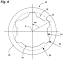
- FIG 8 alternatively has an imprint 40 formed on the rear face 28 of the screw 20, constituting a cylinder parallel to the axis of the screw A, comprising a succession of five identical regular shapes each covering an angle of 60°, included between the circles centered on the axis A, of small radius R1 and large radius R2.
- Each regular shape has an arc of a circle which follows the small radius R1, then a lobe 42 formed by an arc of a circle of convex radius Re- turned outwards, which goes to the outer circle of large radius R2.
- One of the lobes is absent, leaving in its place at an angle of 60° a particular arc-shaped shape 44 which follows the inner circle of small radius R1.
- a method of manufacturing the imprint 40 of the screw 20, simple to implement comprises a succession of five drillings to form the lobes 42, then milling centered on the axis following the small radius R1, to complete the cylindrical shape of this imprint.
- the screw 20 according to the invention as well as the specific screwdriver 50 provide the surgeon with ease, safety and speed in carrying out surgical operations using this type of screw.
- the imprint 40 of the screw 20 may have other shapes.
- standardized shapes may be used, such as a hexagonal shape which is easier to produce, but has a reduced torque transmission capacity.
Landscapes
- Health & Medical Sciences (AREA)
- Orthopedic Medicine & Surgery (AREA)
- Life Sciences & Earth Sciences (AREA)
- Surgery (AREA)
- Medical Informatics (AREA)
- Engineering & Computer Science (AREA)
- Biomedical Technology (AREA)
- Heart & Thoracic Surgery (AREA)
- Nuclear Medicine, Radiotherapy & Molecular Imaging (AREA)
- Molecular Biology (AREA)
- Animal Behavior & Ethology (AREA)
- General Health & Medical Sciences (AREA)
- Public Health (AREA)
- Veterinary Medicine (AREA)
- Neurology (AREA)
- Surgical Instruments (AREA)
Claims (12)
- Spannschraube für die Osteosynthese, umfassend ein Gewinde (22), das entlang einer Hauptachse (A) angeordnet ist, und eine Vertiefung (40) an ihrem hinteren Ende, die um die Hauptachse (A) herum rechtwinklig verteilte, regelmäßige Formen (42) aufweist, die geeignet sind, komplementäre Formen eines darauf eingreifenden Schraubendrehers (50) aufzunehmen, wobei die hintere Fläche der Schraube (28) eine Neigung in Bezug auf eine Querebene der Schraube (20) aufweist, gekennzeichnet dadurch, dass die Vertiefung der Schraube (40) mindestens eine besondere Form (44) aufweist, die sich von den anderen regelmäßigen Formen (42) unterscheidet, so dass eine eindeutige Ausrichtung des Schraubendrehers erreicht wird, wenn der Schraubendreher in die Vertiefung der Schraube eingreift.
- Spannschraube nach Anspruch 1, dadurch gekennzeichnet, dass sie fünf regelmäßige Formen (42) umfasst.
- Spannschraube nach Anspruch 1 oder 2, dadurch gekennzeichnet, dass die besondere Form (44) um die Achse (A) herum einen Winkelsektor abdeckt, der dem einer regelmäßigen Form (42) entspricht.
- Spannschraube nach einem der vorhergehenden Ansprüche, dadurch gekennzeichnet, dass die regelmäßigen Formen (42) Vorsprünge bilden, die auf einem Kranz angeordnet sind, der auf der Achse (A) zentriert ist und zwischen einem Innenkreis mit kleinem Radius (R1) und einem Außenkreis mit großem Radius (R2) liegt.
- Spannschraube nach einem der Ansprüche 1 bis 3, dadurch gekennzeichnet, dass die regelmäßigen Formen (42) einen ersten Kreisbogen, der auf der Achse (A) zentriert ist, und dann einen zweiten Kreisbogen (Re) umfassen, der in Bezug auf den ersten Kreisbogen nach außen übersteht.
- Spannschraube nach einem der vorhergehenden Ansprüche, dadurch gekennzeichnet, dass die besondere Form (44) einen konstanten Radius (R1) aufweist, der auf der Achse (A) zentriert ist.
- Spannschraube nach einem der vorhergehenden Ansprüche, dadurch gekennzeichnet, dass die Vertiefung (40) eine insgesamt zylindrische Form umfasst, die parallel zur Achse (A) angeordnet ist und einen leicht konischen Teil enthält.
- Spannschraube nach einem der vorhergehenden Ansprüche, dadurch gekennzeichnet, dass sich ihr Gewinde (22) über die gesamte Länge der Schraube (20) erstreckt und einen größeren Durchmesser auf der Rückseite der Schraube (20) aufweist.
- Spannschraube nach einem der Ansprüche 1 bis 7, dadurch gekennzeichnet, dass sie ein vorderes Gewinde, das sich über einen vorderen Teil der Länge der Schraube (20) erstreckt, und ein Kopfgewinde umfasst, das hinter der Schraube (20) angeordnet ist, getrennt vom vorderen Gewinde ist und einen größeren Durchmesser als das vordere Gewinde aufweist.
- Spannschraube nach einem der vorhergehenden Ansprüche und Schraubendreher, der dazu vorgesehen ist, solche Schrauben festzuziehen, wobei der Schraubendreher vorne eine Spitze (52) umfasst, die Formen aufweist, die komplementär zu denen der Vertiefung (40) sind und ermöglichen, in diese einzugreifen.
- Spannschraube und Schraubendreher nach Anspruch 10, dadurch gekennzeichnet, dass der Schraubendreher eine visuelle Winkelmarkierung (58) umfasst.
- Spannschraube und Schraubendreher nach Anspruch 10 oder 11, dadurch gekennzeichnet, dass die Spitze (52) des Schraubendrehers eine insgesamt zylindrische Form umfasst, die parallel zur Achse angeordnet ist und einen leicht konischen Teil enthält, um ein Arretieren der Schraube am Schraubendreher zu ermöglichen.
Priority Applications (1)
| Application Number | Priority Date | Filing Date | Title |
|---|---|---|---|
| EP25167518.7A EP4570202A3 (de) | 2017-02-22 | 2018-02-20 | Knochenschraube mit winkelindexierung für den schraubendreher |
Applications Claiming Priority (2)
| Application Number | Priority Date | Filing Date | Title |
|---|---|---|---|
| FR1751390A FR3063005B1 (fr) | 2017-02-22 | 2017-02-22 | Vis pour osteosynthese comportant un indexage angulaire par rapport au tournevis |
| PCT/FR2018/050396 WO2018154225A1 (fr) | 2017-02-22 | 2018-02-20 | Vis pour ostéosynthèse comportant un indexage angulaire par rapport au tournevis |
Related Child Applications (1)
| Application Number | Title | Priority Date | Filing Date |
|---|---|---|---|
| EP25167518.7A Division EP4570202A3 (de) | 2017-02-22 | 2018-02-20 | Knochenschraube mit winkelindexierung für den schraubendreher |
Publications (3)
| Publication Number | Publication Date |
|---|---|
| EP3585289A1 EP3585289A1 (de) | 2020-01-01 |
| EP3585289C0 EP3585289C0 (de) | 2025-04-02 |
| EP3585289B1 true EP3585289B1 (de) | 2025-04-02 |
Family
ID=58501731
Family Applications (2)
| Application Number | Title | Priority Date | Filing Date |
|---|---|---|---|
| EP25167518.7A Pending EP4570202A3 (de) | 2017-02-22 | 2018-02-20 | Knochenschraube mit winkelindexierung für den schraubendreher |
| EP18710093.8A Active EP3585289B1 (de) | 2017-02-22 | 2018-02-20 | Osteosyntheseschraube mit konstanter orientierung in bezug auf den schraubendreher |
Family Applications Before (1)
| Application Number | Title | Priority Date | Filing Date |
|---|---|---|---|
| EP25167518.7A Pending EP4570202A3 (de) | 2017-02-22 | 2018-02-20 | Knochenschraube mit winkelindexierung für den schraubendreher |
Country Status (5)
| Country | Link |
|---|---|
| US (1) | US11207113B2 (de) |
| EP (2) | EP4570202A3 (de) |
| ES (1) | ES3025882T3 (de) |
| FR (1) | FR3063005B1 (de) |
| WO (1) | WO2018154225A1 (de) |
Families Citing this family (3)
| Publication number | Priority date | Publication date | Assignee | Title |
|---|---|---|---|---|
| US11426225B2 (en) * | 2019-12-03 | 2022-08-30 | DePuy Synthes Products, Inc. | Screw extraction shaft |
| FR3119308B1 (fr) | 2021-02-01 | 2023-04-07 | Novastep | Vis pour ostéosynthèse comportant un indexage angulaire par rapport au tournevis et à compatibilité universelle |
| WO2025155566A1 (en) * | 2024-01-17 | 2025-07-24 | In2Bones, LLC | Mis beveled driver for implanting ibs bone compression screws |
Citations (4)
| Publication number | Priority date | Publication date | Assignee | Title |
|---|---|---|---|---|
| FR2760628A1 (fr) * | 1997-03-11 | 1998-09-18 | Biotech International | Vis a tete filetee pour l'osteosynthese de fragments d'os |
| FR2808182B1 (fr) * | 2000-04-28 | 2002-10-31 | Newdeal Sa | Broche chirurgicale de compression pour la solidarisation de phalanges |
| EP1302180A2 (de) * | 2001-10-12 | 2003-04-16 | HS West Investments, LLC | Interferenzschrauben mit vergrösserten proximalem Durchmesser |
| EP2740425B1 (de) * | 2012-12-10 | 2015-09-16 | Biedermann Technologies GmbH & Co. KG | Verankerungselement, das sich für die Verwendung in einer polyaxialen Knochenverankerungsvorrichtung mit verlängertem Drehwinkel auf einer Seite |
Family Cites Families (5)
| Publication number | Priority date | Publication date | Assignee | Title |
|---|---|---|---|---|
| US6387129B2 (en) * | 1998-03-18 | 2002-05-14 | Arthrex, Inc. | Bicortical tibial fixation of ACL grafts |
| US8029539B2 (en) * | 2007-12-19 | 2011-10-04 | X-Spine Systems, Inc. | Offset multiaxial or polyaxial screw, system and assembly |
| US9579188B2 (en) * | 2010-03-10 | 2017-02-28 | Smith & Nephew, Inc. | Anchor having a controlled driver orientation |
| MX2016006587A (es) * | 2013-11-20 | 2016-08-05 | Smith & Nephew Inc | Ancla que tiene una orientacion de destornillador controlada. |
| FR3021571B1 (fr) * | 2014-06-02 | 2017-10-27 | Novastep | Organe de serrage a lobes coniques pour vis hexalobulaire et vis hexalobulaire a lobes coniques |
-
2017
- 2017-02-22 FR FR1751390A patent/FR3063005B1/fr active Active
-
2018
- 2018-02-20 EP EP25167518.7A patent/EP4570202A3/de active Pending
- 2018-02-20 EP EP18710093.8A patent/EP3585289B1/de active Active
- 2018-02-20 US US16/483,230 patent/US11207113B2/en active Active
- 2018-02-20 ES ES18710093T patent/ES3025882T3/es active Active
- 2018-02-20 WO PCT/FR2018/050396 patent/WO2018154225A1/fr not_active Ceased
Patent Citations (4)
| Publication number | Priority date | Publication date | Assignee | Title |
|---|---|---|---|---|
| FR2760628A1 (fr) * | 1997-03-11 | 1998-09-18 | Biotech International | Vis a tete filetee pour l'osteosynthese de fragments d'os |
| FR2808182B1 (fr) * | 2000-04-28 | 2002-10-31 | Newdeal Sa | Broche chirurgicale de compression pour la solidarisation de phalanges |
| EP1302180A2 (de) * | 2001-10-12 | 2003-04-16 | HS West Investments, LLC | Interferenzschrauben mit vergrösserten proximalem Durchmesser |
| EP2740425B1 (de) * | 2012-12-10 | 2015-09-16 | Biedermann Technologies GmbH & Co. KG | Verankerungselement, das sich für die Verwendung in einer polyaxialen Knochenverankerungsvorrichtung mit verlängertem Drehwinkel auf einer Seite |
Also Published As
| Publication number | Publication date |
|---|---|
| FR3063005B1 (fr) | 2021-11-12 |
| EP3585289A1 (de) | 2020-01-01 |
| US11207113B2 (en) | 2021-12-28 |
| FR3063005A1 (fr) | 2018-08-24 |
| EP3585289C0 (de) | 2025-04-02 |
| US20200229853A1 (en) | 2020-07-23 |
| WO2018154225A1 (fr) | 2018-08-30 |
| ES3025882T3 (en) | 2025-06-10 |
| EP4570202A2 (de) | 2025-06-18 |
| EP4570202A3 (de) | 2025-08-20 |
Similar Documents
| Publication | Publication Date | Title |
|---|---|---|
| EP2393441B1 (de) | Osteosynthese- und arthrodese-schraube | |
| EP2405837B1 (de) | Wirbelsäulenimplantat mit arretierbarer kugel-verbindung | |
| US10828066B2 (en) | External fixator assembly | |
| EP1378205B1 (de) | Kompressionsschraube für die Osteosynthese | |
| EP2449985B2 (de) | Orthopädisches Frässwerkzeug zum Vorbereitung von Knochen, insbesondere zum Vorbereitung von Schultergelenkpfanne | |
| US10499951B2 (en) | External fixator assembly | |
| EP1923013A1 (de) | Verfahren zur Herstellung von Überbrückungskämmen | |
| EP3585289B1 (de) | Osteosyntheseschraube mit konstanter orientierung in bezug auf den schraubendreher | |
| FR2760628A1 (fr) | Vis a tete filetee pour l'osteosynthese de fragments d'os | |
| FR3099875A1 (fr) | Implant intramédullaire pour ostéotomie transversale | |
| CA2662767A1 (fr) | Appareil chirurgical pour osteosynthese | |
| FR2743490A1 (fr) | Agrafe d'arthrodese et instruments ancillaires pour la pose d'une telle agrafe | |
| WO2022162326A1 (fr) | Vis pour ostéosynthèse comportant un indexage angulaire par rapport au tournevis et à compatibilité universelle | |
| FR2625430A1 (fr) | Vis de blocage d'une plaque d'osteosynthese et procede de fabrication d'une telle vis | |
| CA2220638A1 (fr) | Bague d'osteosynthese utilisable en combinaison avec une broche ou une vis, et ancillaire pour sa mise en compression | |
| FR2738475A1 (fr) | Pince de presentation de plaques d'osteosynthese maxillo-faciale | |
| WO2013175099A1 (fr) | Vis autocompressive d'osteosynthese | |
| EP1139893A1 (de) | Autokompressive osteosyntheseschraube zur chirurgie von kleinen knochen | |
| FR2912895A1 (fr) | Materiel d'arthodese | |
| FR2638630A1 (fr) | Broche pour haubanage et cerclage en chirurgie osseuse et son impacteur | |
| FR2899787A1 (fr) | Vis pour la reduction d'une fracture de l'apophyse odontoire | |
| EP3003183A1 (de) | Osteosynthesevorrichtung mit einer cervico-cephalon-schraube | |
| FR2728455A1 (fr) | Dispositif d'osteosynthese | |
| FR2876897A1 (fr) | Perfectionnement aux vis chirurgicales implantables | |
| FR3093283A1 (fr) | Ensemble d’ostéosynthèse pour fracture d’un humérus |
Legal Events
| Date | Code | Title | Description |
|---|---|---|---|
| STAA | Information on the status of an ep patent application or granted ep patent |
Free format text: STATUS: UNKNOWN |
|
| STAA | Information on the status of an ep patent application or granted ep patent |
Free format text: STATUS: THE INTERNATIONAL PUBLICATION HAS BEEN MADE |
|
| PUAI | Public reference made under article 153(3) epc to a published international application that has entered the european phase |
Free format text: ORIGINAL CODE: 0009012 |
|
| STAA | Information on the status of an ep patent application or granted ep patent |
Free format text: STATUS: REQUEST FOR EXAMINATION WAS MADE |
|
| 17P | Request for examination filed |
Effective date: 20190919 |
|
| AK | Designated contracting states |
Kind code of ref document: A1 Designated state(s): AL AT BE BG CH CY CZ DE DK EE ES FI FR GB GR HR HU IE IS IT LI LT LU LV MC MK MT NL NO PL PT RO RS SE SI SK SM TR |
|
| AX | Request for extension of the european patent |
Extension state: BA ME |
|
| DAV | Request for validation of the european patent (deleted) | ||
| DAX | Request for extension of the european patent (deleted) | ||
| TPAC | Observations filed by third parties |
Free format text: ORIGINAL CODE: EPIDOSNTIPA |
|
| STAA | Information on the status of an ep patent application or granted ep patent |
Free format text: STATUS: EXAMINATION IS IN PROGRESS |
|
| 17Q | First examination report despatched |
Effective date: 20230404 |
|
| RAP3 | Party data changed (applicant data changed or rights of an application transferred) |
Owner name: NOVASTEP |
|
| GRAP | Despatch of communication of intention to grant a patent |
Free format text: ORIGINAL CODE: EPIDOSNIGR1 |
|
| STAA | Information on the status of an ep patent application or granted ep patent |
Free format text: STATUS: GRANT OF PATENT IS INTENDED |
|
| INTG | Intention to grant announced |
Effective date: 20241108 |
|
| GRAS | Grant fee paid |
Free format text: ORIGINAL CODE: EPIDOSNIGR3 |
|
| GRAA | (expected) grant |
Free format text: ORIGINAL CODE: 0009210 |
|
| STAA | Information on the status of an ep patent application or granted ep patent |
Free format text: STATUS: THE PATENT HAS BEEN GRANTED |
|
| AK | Designated contracting states |
Kind code of ref document: B1 Designated state(s): AL AT BE BG CH CY CZ DE DK EE ES FI FR GB GR HR HU IE IS IT LI LT LU LV MC MK MT NL NO PL PT RO RS SE SI SK SM TR |
|
| REG | Reference to a national code |
Ref country code: GB Ref legal event code: FG4D Free format text: NOT ENGLISH |
|
| REG | Reference to a national code |
Ref country code: CH Ref legal event code: EP |
|
| REG | Reference to a national code |
Ref country code: IE Ref legal event code: FG4D Free format text: LANGUAGE OF EP DOCUMENT: FRENCH |
|
| REG | Reference to a national code |
Ref country code: DE Ref legal event code: R096 Ref document number: 602018080682 Country of ref document: DE |
|
| U01 | Request for unitary effect filed |
Effective date: 20250417 |
|
| U07 | Unitary effect registered |
Designated state(s): AT BE BG DE DK EE FI FR IT LT LU LV MT NL PT RO SE SI Effective date: 20250425 |
|
| REG | Reference to a national code |
Ref country code: ES Ref legal event code: FG2A Ref document number: 3025882 Country of ref document: ES Kind code of ref document: T3 Effective date: 20250610 |
|
| PG25 | Lapsed in a contracting state [announced via postgrant information from national office to epo] |
Ref country code: GR Free format text: LAPSE BECAUSE OF FAILURE TO SUBMIT A TRANSLATION OF THE DESCRIPTION OR TO PAY THE FEE WITHIN THE PRESCRIBED TIME-LIMIT Effective date: 20250703 Ref country code: NO Free format text: LAPSE BECAUSE OF FAILURE TO SUBMIT A TRANSLATION OF THE DESCRIPTION OR TO PAY THE FEE WITHIN THE PRESCRIBED TIME-LIMIT Effective date: 20250702 |
|
| PG25 | Lapsed in a contracting state [announced via postgrant information from national office to epo] |
Ref country code: PL Free format text: LAPSE BECAUSE OF FAILURE TO SUBMIT A TRANSLATION OF THE DESCRIPTION OR TO PAY THE FEE WITHIN THE PRESCRIBED TIME-LIMIT Effective date: 20250402 |
|
| PG25 | Lapsed in a contracting state [announced via postgrant information from national office to epo] |
Ref country code: HR Free format text: LAPSE BECAUSE OF FAILURE TO SUBMIT A TRANSLATION OF THE DESCRIPTION OR TO PAY THE FEE WITHIN THE PRESCRIBED TIME-LIMIT Effective date: 20250402 |
|
| PG25 | Lapsed in a contracting state [announced via postgrant information from national office to epo] |
Ref country code: RS Free format text: LAPSE BECAUSE OF FAILURE TO SUBMIT A TRANSLATION OF THE DESCRIPTION OR TO PAY THE FEE WITHIN THE PRESCRIBED TIME-LIMIT Effective date: 20250702 |
|
| PG25 | Lapsed in a contracting state [announced via postgrant information from national office to epo] |
Ref country code: IS Free format text: LAPSE BECAUSE OF FAILURE TO SUBMIT A TRANSLATION OF THE DESCRIPTION OR TO PAY THE FEE WITHIN THE PRESCRIBED TIME-LIMIT Effective date: 20250802 |
|
| PG25 | Lapsed in a contracting state [announced via postgrant information from national office to epo] |
Ref country code: SM Free format text: LAPSE BECAUSE OF FAILURE TO SUBMIT A TRANSLATION OF THE DESCRIPTION OR TO PAY THE FEE WITHIN THE PRESCRIBED TIME-LIMIT Effective date: 20250402 |
|
| PG25 | Lapsed in a contracting state [announced via postgrant information from national office to epo] |
Ref country code: CZ Free format text: LAPSE BECAUSE OF FAILURE TO SUBMIT A TRANSLATION OF THE DESCRIPTION OR TO PAY THE FEE WITHIN THE PRESCRIBED TIME-LIMIT Effective date: 20250402 |
|
| PG25 | Lapsed in a contracting state [announced via postgrant information from national office to epo] |
Ref country code: SK Free format text: LAPSE BECAUSE OF FAILURE TO SUBMIT A TRANSLATION OF THE DESCRIPTION OR TO PAY THE FEE WITHIN THE PRESCRIBED TIME-LIMIT Effective date: 20250402 |
|
| PLBE | No opposition filed within time limit |
Free format text: ORIGINAL CODE: 0009261 |
|
| STAA | Information on the status of an ep patent application or granted ep patent |
Free format text: STATUS: NO OPPOSITION FILED WITHIN TIME LIMIT |
|
| REG | Reference to a national code |
Ref country code: CH Ref legal event code: L10 Free format text: ST27 STATUS EVENT CODE: U-0-0-L10-L00 (AS PROVIDED BY THE NATIONAL OFFICE) Effective date: 20260211 |