EP3585010B1 - Routingprioritätskonfigurationsverfahren, -vorrichtung und -steuergerät - Google Patents
Routingprioritätskonfigurationsverfahren, -vorrichtung und -steuergerät Download PDFInfo
- Publication number
- EP3585010B1 EP3585010B1 EP18764306.9A EP18764306A EP3585010B1 EP 3585010 B1 EP3585010 B1 EP 3585010B1 EP 18764306 A EP18764306 A EP 18764306A EP 3585010 B1 EP3585010 B1 EP 3585010B1
- Authority
- EP
- European Patent Office
- Prior art keywords
- route
- target device
- controller
- address
- devices
- Prior art date
- Legal status (The legal status is an assumption and is not a legal conclusion. Google has not performed a legal analysis and makes no representation as to the accuracy of the status listed.)
- Active
Links
Images


Classifications
-
- H—ELECTRICITY
- H04—ELECTRIC COMMUNICATION TECHNIQUE
- H04L—TRANSMISSION OF DIGITAL INFORMATION, e.g. TELEGRAPHIC COMMUNICATION
- H04L45/00—Routing or path finding of packets in data switching networks
- H04L45/302—Route determination based on requested QoS
-
- H—ELECTRICITY
- H04—ELECTRIC COMMUNICATION TECHNIQUE
- H04L—TRANSMISSION OF DIGITAL INFORMATION, e.g. TELEGRAPHIC COMMUNICATION
- H04L45/00—Routing or path finding of packets in data switching networks
- H04L45/24—Multipath
-
- H—ELECTRICITY
- H04—ELECTRIC COMMUNICATION TECHNIQUE
- H04L—TRANSMISSION OF DIGITAL INFORMATION, e.g. TELEGRAPHIC COMMUNICATION
- H04L41/00—Arrangements for maintenance, administration or management of data switching networks, e.g. of packet switching networks
- H04L41/08—Configuration management of networks or network elements
-
- H—ELECTRICITY
- H04—ELECTRIC COMMUNICATION TECHNIQUE
- H04L—TRANSMISSION OF DIGITAL INFORMATION, e.g. TELEGRAPHIC COMMUNICATION
- H04L45/00—Routing or path finding of packets in data switching networks
- H04L45/24—Multipath
- H04L45/245—Link aggregation, e.g. trunking
-
- H—ELECTRICITY
- H04—ELECTRIC COMMUNICATION TECHNIQUE
- H04L—TRANSMISSION OF DIGITAL INFORMATION, e.g. TELEGRAPHIC COMMUNICATION
- H04L45/00—Routing or path finding of packets in data switching networks
- H04L45/302—Route determination based on requested QoS
- H04L45/306—Route determination based on the nature of the carried application
-
- H—ELECTRICITY
- H04—ELECTRIC COMMUNICATION TECHNIQUE
- H04L—TRANSMISSION OF DIGITAL INFORMATION, e.g. TELEGRAPHIC COMMUNICATION
- H04L45/00—Routing or path finding of packets in data switching networks
- H04L45/42—Centralised routing
-
- H—ELECTRICITY
- H04—ELECTRIC COMMUNICATION TECHNIQUE
- H04L—TRANSMISSION OF DIGITAL INFORMATION, e.g. TELEGRAPHIC COMMUNICATION
- H04L47/00—Traffic control in data switching networks
- H04L47/70—Admission control; Resource allocation
- H04L47/82—Miscellaneous aspects
- H04L47/821—Prioritising resource allocation or reservation requests
-
- H—ELECTRICITY
- H04—ELECTRIC COMMUNICATION TECHNIQUE
- H04L—TRANSMISSION OF DIGITAL INFORMATION, e.g. TELEGRAPHIC COMMUNICATION
- H04L49/00—Packet switching elements
- H04L49/25—Routing or path finding in a switch fabric
-
- H—ELECTRICITY
- H04—ELECTRIC COMMUNICATION TECHNIQUE
- H04L—TRANSMISSION OF DIGITAL INFORMATION, e.g. TELEGRAPHIC COMMUNICATION
- H04L61/00—Network arrangements, protocols or services for addressing or naming
- H04L61/50—Address allocation
- H04L61/5007—Internet protocol [IP] addresses
-
- H—ELECTRICITY
- H04—ELECTRIC COMMUNICATION TECHNIQUE
- H04L—TRANSMISSION OF DIGITAL INFORMATION, e.g. TELEGRAPHIC COMMUNICATION
- H04L12/00—Data switching networks
- H04L12/28—Data switching networks characterised by path configuration, e.g. LAN [Local Area Networks] or WAN [Wide Area Networks]
- H04L12/46—Interconnection of networks
- H04L12/4641—Virtual LANs, VLANs, e.g. virtual private networks [VPN]
-
- H—ELECTRICITY
- H04—ELECTRIC COMMUNICATION TECHNIQUE
- H04L—TRANSMISSION OF DIGITAL INFORMATION, e.g. TELEGRAPHIC COMMUNICATION
- H04L12/00—Data switching networks
- H04L12/66—Arrangements for connecting between networks having differing types of switching systems, e.g. gateways
-
- H—ELECTRICITY
- H04—ELECTRIC COMMUNICATION TECHNIQUE
- H04L—TRANSMISSION OF DIGITAL INFORMATION, e.g. TELEGRAPHIC COMMUNICATION
- H04L2101/00—Indexing scheme associated with group H04L61/00
- H04L2101/60—Types of network addresses
- H04L2101/618—Details of network addresses
- H04L2101/622—Layer-2 addresses, e.g. medium access control [MAC] addresses
-
- H—ELECTRICITY
- H04—ELECTRIC COMMUNICATION TECHNIQUE
- H04L—TRANSMISSION OF DIGITAL INFORMATION, e.g. TELEGRAPHIC COMMUNICATION
- H04L45/00—Routing or path finding of packets in data switching networks
- H04L45/66—Layer 2 routing, e.g. in Ethernet based MAN's
-
- H—ELECTRICITY
- H04—ELECTRIC COMMUNICATION TECHNIQUE
- H04L—TRANSMISSION OF DIGITAL INFORMATION, e.g. TELEGRAPHIC COMMUNICATION
- H04L69/00—Network arrangements, protocols or services independent of the application payload and not provided for in the other groups of this subclass
- H04L69/30—Definitions, standards or architectural aspects of layered protocol stacks
- H04L69/32—Architecture of open systems interconnection [OSI] 7-layer type protocol stacks, e.g. the interfaces between the data link level and the physical level
- H04L69/322—Intralayer communication protocols among peer entities or protocol data unit [PDU] definitions
- H04L69/325—Intralayer communication protocols among peer entities or protocol data unit [PDU] definitions in the network layer [OSI layer 3], e.g. X.25
Definitions
- the present invention relates to the field of communications technologies, and in particular, to a route priority configuration method, a device, and a controller.
- a virtual extensible local area network (English: virtual extensible local area network, VXLAN) is a network virtualization technology.
- VXLAN gateway When a device needs to access a virtualized network, a VXLAN gateway needs to be used.
- the VXLAN gateway may provide packet transmission for the device.
- a VXLAN distributed gateway technology is proposed currently.
- the VXLAN distributed gateway technology refers to that different VXLAN distributed gateways deployed on two or more devices are configured with a same IP address and provide a gateway service at the same time.
- VXLAN distributed gateways have the same IP address, and each VXLAN distributed gateway advertises a direct route based on the IP address. Therefore, in a VXLAN distributed gateway scenario, direct routes corresponding to layer 3 interfaces configured on the devices form equal-cost multi-path (English: equal-cost multi-path, ECMP).
- the direct route is defined relative to a remote route.
- the direct route is generated by a device based on an IP address of an interface of the device.
- the remote route is generated based on an IP address of an interface of another device.
- the ECMP indicates a plurality of different paths to a same destination IP address or a same destination network segment. The plurality of paths have same costs. However, because all ECMP occupies hardware resources of a device, ECMP needs to be avoided when the ECMP cannot be used or is not required by a user.
- route priorities of direct routes that can form ECMP are manually modified to avoid unnecessary ECMP.
- a workload of modifying the route priorities is relatively heavy, and an error is very likely to occur in a manual modification manner, thereby affecting route priority configuration efficiency.
- US 2017/0026273 A1 describes a traffic switching method, a device, and a system where, a software-defined networking (SDN) controller acquires a first state of a target gateway, where the target gateway belongs to an SDN gateway group, the SDN gateway group is used to forward traffic that is transmitted between a first network node and a second network node, and multiple forwarding paths on which multiple gateways in the SDN gateway group are located form multiple equal-cost paths between the first network node and the second network node.
- SDN software-defined networking
- the SDN controller sends an Address Resolution Protocol (ARP) entry to the target gateway according to the first state, and changes, of the multiple equal-cost paths, a metric value of a forwarding path on which the target gateway is located from an original value to a first value, where the first value is greater than the original value.
- ARP Address Resolution Protocol
- WO 2016/004874 A1 describes that Priority of a route, which carries a virtual extensible local area network (VXLAN) tunneling end point (VTEP) Internet protocol (IP) address of a port of a VXLAN tunnel corresponding to a first VXLAN IP GW to be mi grated, is lowered. The route is then released to a VTEP at peer end of the VXLAN tunnel. Priority of a static route destined for a virtual machine (VM) is also lowered. The static route is then released to a network device in a non-virtual network. At least two VXLAN IP GWs possess a same VTEP IP address of a port of a VXLAN tunnel.
- VXLAN virtual extensible local area network
- IP Internet protocol
- priority of route carrying the same VTEP IP address released by each of at least two VXLAN IP GWs is same.
- Priority of static route from each of at least two VXLAN IP GWs to the VM is same.
- Embodiments of the present invention provide a route priority configuration method, a device, and a controller, so that direct routes generated based on a same IP address can correspond to different route priorities, to avoid a case in which direct routes advertised by different distributed gateways form ECMP, and improve route priority configuration efficiency.
- the invention is defined by the appended independent claims, wherein preferred embodiments are defined in the dependent claims.
- FIG. 1 is a schematic diagram of a possible VXLAN distributed gateway deployment scenario according to an embodiment of the present invention.
- the scenario includes spine (spine) switches, leaf (leaf) switches, and servers.
- the leaf switch is connected to the server, and the spine switch is connected to the leaf switch.
- the leaf switches include a device 1, a device 2, and a device 3.
- a VXLAN distributed gateway is usually deployed on the leaf switch.
- VXLAN distributed gateways may be deployed on the device 1 and the device 2 in the leaf switches, and IP addresses of the VXLAN distributed gateways each are 192.168.0.1.
- One path is from the spine switch to the device 1, and the other path is from the spine switch to the device 2.
- the two paths form ECMP.
- a spine switch that sends a data packet forwards the data packet through the two paths in a load balancing mode.
- a route is selected based on a longest match principle in terms of a mask length.
- the mask length indicates a quantity of 1s included in 32 bits corresponding to a four-byte field that represents a subnet mask.
- the subnet mask is 255.255.255.0, and therefore, the mask length is 24 bits.
- each leaf switch is connected to at least two servers, and provides a communication service for the at least two servers. Therefore, a subnet mask configured for the leaf switch is less than 32 bits.
- a subnet mask configured for the device 1 in the leaf switches is 255.255.255.0, and therefore, a mask length of a direct route corresponding to the device 1 is 24 bits.
- a routing table of the device 4 includes a plurality of pieces of routing information with different mask lengths, and there is another route whose mask length is greater than the mask length of the direct route. Therefore, the device 4 selects a route with a longest mask length to forward the packet. Therefore, it can be learned that the direct route is not used to forward a specific service, and all ECMP formed by different direct routes that are generated based on a same IP address occupies hardware resources such as memory resources of a device. Consequently, the hardware resources of the device are wasted.
- route priorities corresponding to the direct routes that can form the ECMP need to be manually modified.
- a workload of modifying the route priorities is heavy, and an error is very likely to occur in a manual modification manner, affecting route priority configuration efficiency.
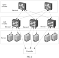
- FIG. 2 is a schematic diagram of another possible VXLAN distributed gateway deployment scenario according to an embodiment of the present invention.
- a controller is added based on the schematic diagram of the scenario shown in FIG. 1 .
- the controller may be connected to a leaf switch.
- VXLAN distributed gateways may be deployed on a device 1 and a device 2 in leaf switches, and IP addresses of the VXLAN distributed gateways each are 192.168.0.1.
- the device 1 is used as an example for description.
- the controller receives an interface creation request for creating a layer 3 interface on the device 1, where the interface creation request carries the IP address 192.168.0.1 (namely, the IP addresses of the distributed gateways) and a subnet mask configured for the layer 3 interface; the controller generates a direct route of the layer 3 interface based on the interface creation request; the controller allocates a route priority to the direct route according to a preset allocation rule; and the controller sends the direct route and the route priority corresponding to the direct route to the device 1.
- the interface creation request carries the IP address 192.168.0.1 (namely, the IP addresses of the distributed gateways) and a subnet mask configured for the layer 3 interface
- the controller generates a direct route of the layer 3 interface based on the interface creation request
- the controller allocates a route priority to the direct route according to a preset allocation rule
- the controller sends the direct route and the route priority corresponding to the direct route to the device 1.
- the controller may also complete configuration according to the execution process performed for the device 1, and a route priority allocated to a direct route that is of the device 2 and that is generated based on 192.168.0.1 is different from a route priority allocated to a direct route that is of the device 1 and that is generated based on 192.168.0.1.
- a factor of a route priority is considered for route selection between any spine switch and the destination address 192.168.0.1, to avoid a case in which different direct routes form ECMP, reduce a workload caused by manually modifying the route priorities, and improve route priority configuration efficiency.
- FIG. 3 is an architectural diagram of a possible network system according to an embodiment of the present invention.
- the network system in FIG. 3 includes a controller, a device A, and a device B.
- the device A and the device B are deployed with distributed gateways, and the distributed gateways on the device A and the device B have a same IP address.
- the controller may directly establish a communication connection to the device A and the device B.
- FIG. 4 is an architectural diagram of another possible network system according to an embodiment of the present invention.
- the network system in FIG. 4 includes a controller, a device A, a device B, and a device C.
- the device A and the device B are deployed with distributed gateways, and the distributed gateways on the device A and the device B have a same IP address.
- the controller may establish a communication connection to the device A and the device B by using the device C.
- a route priority configuration method in the embodiments of the present invention may be applied to another system in which a route priority corresponding to a route needs to be configured, for example, a virtual local area network (English: virtual local area network, VLAN). This is not limited in the embodiments of the present invention.
- a target device or another device in the embodiments of the present invention may include but is not limited to a device that has a routing and transfer function, for example, a router or a switch.
- a controller may be any device that has a communication function and a management function, for example, a server, a terminal (terminal), or a mobile station (English: mobile station, MS).
- a controller may be a mobile phone (or referred to as a "cellular" phone), or may be a portable, pocket-sized, handheld, computer built-in, or in-vehicle mobile apparatus (a smart band, a smartwatch, smart glasses, or the like).
- FIG. 5 is a schematic flowchart of a route priority configuration method according to an embodiment of the present invention.
- the route priority configuration method in this embodiment of the present invention is jointly performed by a controller and a target device.
- the target device may be either one of the device A and the device B in the architectural diagram of the network system shown in FIG. 3 or FIG. 4 .
- the controller and the target device in this embodiment of the present invention may have other names. All devices fall within the scope of the claims of the present invention and equivalent technologies of the present invention, provided that functions of the devices are similar to those in the present invention.
- For a specific process of the route priority configuration method refer to the following detailed description.
- the target device sends a registration request to the controller, where the registration request carries a MAC address of the target device.
- the target device after being powered on, the target device sends the registration request to the controller, and the registration request carries the media access control (English: media access control, MAC) address of the target device. Because different devices have different MAC addresses, the registration request carries the MAC address, so that the controller can determine a device that sends the registration request.
- media access control English: media access control, MAC
- the target device may send the registration request to the controller in a format of a simple network management protocol (English: Simple Network Management Protocol, SNMP).
- a simple network management protocol English: Simple Network Management Protocol, SNMP.
- the controller receives the registration request sent by the target device, and verifies the registration request from the target device. For example, the controller verifies whether the MAC address of the target device is valid. After the controller determines that the target device is successfully registered, the controller establishes a communication connection to the target device. Optionally, the controller may establish a communication connection to the target device by using a Network Configuration Protocol (English: Network Configuration, Netconf).
- a Network Configuration Protocol English: Network Configuration, Netconf
- the controller determines, based on the MAC address of the target device, a device identifier corresponding to the target device.
- the controller may directly determine the MAC address of the target device as the device identifier of the target device.
- the controller may generate, based on the MAC address of the target device, another device identifier used to uniquely identify the target device.
- a process of determining the device identifier of the target device is not limited in this embodiment of the present invention.
- the generated device identifier may be represented by using less than six bytes, to reduce bit resource consumption in a transmission process of the device identifier.
- the controller receives an interface creation request for creating a layer 3 interface on the target device.
- the interface creation request carries an IP address and a subnet mask configured for the layer 3 interface. Creating the layer 3 interface on the target device indicates that the target device is allowed to work at a network layer.
- the subnet mask is used to determine a network segment within which a data packet may be transmitted by using the layer 3 interface.
- the IP address carried in the interface creation request is an IP address of the distributed gateway.
- the interface creation request may be initiated by a user on an operation platform corresponding to the controller, and the IP address and the subnet mask that are carried in the interface creation request may also be configured on the operation platform.
- the controller generates a direct route of the layer 3 interface based on the interface creation request.
- the controller may generate the direct route corresponding to the layer 3 interface, which is shown in Table 1.
- a server whose IP address falls within 192.168.0.2 to 192.168.0.254 may communicate with a server or a device in another network by using the layer 3 interface.
- the controller allocates a route priority to the direct route according to a preset allocation rule.
- the user may create layer 3 interfaces on a plurality of devices by using the controller.
- layer 3 interfaces created on a same device have different IP addresses, and layer 3 interfaces with a same IP address may be created on different devices.
- distributed gateways may be deployed on two or more devices (namely, at least two devices).
- the preset allocation rule indicates that a route priority corresponding to a direct route that is based on the IP address of the distributed gateway and that is of any one of the at least two devices is different from a route priority corresponding to a direct route that is based on the IP address of the distributed gateway and that is of another device in the at least two devices.
- direct routes generated based on a same IP address correspond to different route priorities. Therefore, a path to a destination IP address may be determined by considering a parameter of the route priority. For example, a path with a highest route priority is selected as the path to the destination IP address. According to the solution of this embodiment of the present invention, generation of unnecessary ECMP can be reduced, thereby saving a hardware resource occupied due to forming of the ECMP.
- the controller may generate, based on the device identifier of the target device and according to the preset allocation rule, the route priority corresponding to the direct route.
- the device identifier is used to uniquely identify the target device, and only one layer 3 interface configured with the IP address can be created on the target device. Therefore, the route priority generated according to the preset allocation rule and by using the device identifier can be distinguished from a route priority that is of another device and that is generated by using a device identifier of the another device.
- the distributed gateways are deployed on the device A and the device B, and the controller may establish a communication connection to the device A and the device B.
- the user may create, on the device A by using the controller, a layer 3 interface I1 whose IP address is 192.168.0.1 and subnet mask is 255.255.255.0; and may create, on the device B, a layer 3 interface I2 whose IP address is 192.168.0.1 and subnet mask is 255.255.255.0.
- a device identifier of the device A is 100
- a device identifier of the device B is 200.
- the controller may generate, based on a preset algorithm, route priorities of direct routes that are of the device A and the device B and that are generated based on the IP address 192.168.0.1.
- the device identifier 100 is directly determined as a route priority corresponding to a direct route that is of the device A and that is generated based on the IP address 192.168.0.1; or the device identifier 100 is increased by a fixed offset, for example, 1, and 101 is determined as a route priority corresponding to a direct route that is the device A and that is generated based on the IP address 192.168.0.1.
- the preset algorithm is not limited in this embodiment of the present invention.
- a route priority of a direct route generated based on the IP address 192.168.0.1 may also be generated based on the device identifier of the device B.
- routing information that includes the direct route and the priority corresponding to the direct route and that corresponds to the layer 3 interface I1 is configured in the device A as shown in Table 2; and routing information corresponding to the layer 3 interface I2 is configured in the device B as shown in Table 3.
- Table 2 Destination address Subnet mask Route priority Layer 3 interface 192.168.0.1 255.255.255.0 101 11
- the controller may generate, based on the device identifiers, a preset basic priority, the preset allocation rule, and a preset algorithm, route priorities of direct routes that are of the device A and the device B and that are generated based on the IP address 192.168.0.1.
- the preset basic priority is 2. Therefore, the device identifier 100 of the device A is added to the preset basic priority 2, to obtain a route priority 102 of a direct route that is of the device A and that is generated by using the IP address 192.168.0.1; and the device identifier 200 of the device B is added to the preset basic priority 2, to obtain a route priority 202 of a direct route that is of the device B and that is generated by the IP address 192.168.0.1.
- the preset algorithm is not limited in this embodiment of the present invention. However, direct routes that are of different devices and that are generated based on a same IP address correspond to different route priorities. Further, optionally, the basic priority may be used to set a default route priority of another route generated for the target device or another device.
- route priorities of direct routes that are of the device A and the device B and that are generated based on the IP address 192.168.0.1 may be separately determined based on content described in the architectural diagram of the network system shown in FIG. 3 . Details are not described herein again.
- the controller sends, to the target device, the direct route and the route priority corresponding to the direct route.
- the target device receives the direct route and the route priority corresponding to the direct route that are sent by the controller.
- the target device stores the direct route and the route priority corresponding to the direct route.
- the controller After the controller allocates the route priority to the direct route of the target device, the controller sends the direct route and the route priority corresponding to the direct route to the target device.
- the target device receives the direct route and the route priority corresponding to the direct route that are sent by the controller, and stores the direct route and the route priority corresponding to the direct route that are received.
- the target device adds routing information that includes the direct route and the priority corresponding to the direct route to a routing table of the target device, and may notify a neighboring device of the added routing information.
- the neighboring device is another device that establishes a communication connection to the target device. In this way, the neighboring device may add, to a routing table of the neighboring device, the routing information added by the target device.
- the controller separately creates, on the device 1 and the device 2, layer 3 interfaces whose IP addresses are 192.168.0.1 and subnet masks are 255.255.255.0.
- a layer 3 interface on the device 1 is I1
- a layer 3 interface on the device 2 is I2.
- the controller sends, to the device 1, a direct route 1 of the layer 3 interface created on the device 1 and a route priority 100 corresponding to the direct route 1; and sends, to the device 2, a direct route 2 of the layer 3 interface created on the device 2 and a route priority 200 corresponding to the direct route 2.
- the device 1 and the device 2 also notify a neighboring device of newly added routing information (the direct route 1 and the direct route 2).
- the device 4 in spine switches receives the routing information notified by the device 1 and the device 2, and stores the routing information in a routing table of the device 4.
- routing information shown in Table 4 exists in the routing table of the device 4.
- the device 4 For the device 4, if the device 4 needs to access the destination address 192.168.0.1, no ECMP is formed because the direct route 1 and the direct route 2 have different route priorities. If a route priority with a larger specified value is higher, it can be learned that the route priority of the direct route 2 corresponding to the layer 3 interface I2 is higher than the route priority of the direct route 1 corresponding to the layer 3 interface Il. A routing policy is selecting a route with a higher priority, and therefore, the device 4 may select the direct route 2 to access 192.168.0.1.
- the controller receives the interface creation request for creating the layer 3 interface on the target device, where the interface creation request carries the IP address and the subnet mask configured for the layer 3 interface; the controller generates the direct route of the layer 3 interface based on the interface creation request; the controller allocates the route priority to the direct route according to the preset allocation rule; and the controller sends, to the target device, the direct route and the route priority corresponding to the direct route.
- the route priority is allocated by using the preset allocation rule, to ensure that different direct routes generated based on a same IP address correspond to different route priorities, thereby avoiding a case in which the different direct routes form ECMP, reducing a workload caused by manually modifying the route priorities, and improving route priority configuration efficiency.
- FIG. 6 is a schematic structural diagram of a controller according to an embodiment of the present invention.
- the controller is configured to implement the route priority configuration method disclosed in the embodiments of the present invention.
- the controller is applied to a network system, and the network system includes the controller and at least two devices.
- the at least two devices are deployed with distributed gateways, and the distributed gateways on the at least two devices have a same IP address.
- a controller 1 provided in this embodiment of the present invention may include a receiving module 11, a generation module 12, an allocation module 13, and a sending module 14.
- the receiving module 11 is configured to receive an interface creation request for creating a layer 3 interface on a target device.
- the interface creation request carries the IP address and a subnet mask configured for the layer 3 interface, and the target device is any one of the at least two devices.
- the generation module 12 is configured to generate, a direct route of the layer 3 interface based on the interface creation request.
- the allocation module 13 is configured to allocate a route priority to the direct route according to a preset allocation rule.
- the sending module 14 is configured to send, to the target device, the direct route and the route priority corresponding to the direct route.
- the preset allocation rule indicates that a route priority corresponding to a direct route that is based on the IP address and that is of any one of the at least two devices is different from a route priority corresponding to a direct route that is based on the IP address and that is of another device in the at least two devices.
- the allocation module 13 is specifically configured to generate, based on a device identifier of the target device and according to the preset allocation rule, the route priority corresponding to the direct route.
- the device identifier is used to uniquely identify the target device.
- the allocation module 13 is specifically configured to generate, based on a device identifier of the target device and a preset basic priority and according to the preset allocation rule, the route priority corresponding to the direct route.
- the device identifier is used to uniquely identify the target device.
- the controller further includes a determining module 15.
- the receiving module 11 is further configured to receive a registration request sent by the target device.
- the registration request carries a media access control MAC address of the target device.
- the determining module 15 is configured to determine, based on the MAC address of the target device, the device identifier corresponding to the target device.
- FIG. 7 is a schematic structural diagram of another controller according to an embodiment of the present invention.
- a controller 700 shown in FIG. 7 includes a processor 701 and a communications interface 702.
- the communications interface 702 is configured to support communication between the controller 700 and the at least two devices on which the distributed gateways are deployed in the foregoing embodiments.
- the processor 701 and the communications interface 702 are communicatively connected, for example, by using a bus.
- the controller 700 may further include a memory 703.
- the memory 703 is configured to store program code and data that are executed by the controller 700, to implement an action of the controller provided in any one of the embodiments shown in FIG. 2 to FIG. 5 .
- the processor 701 is applied to this embodiment of the present invention, and is configured to implement functions of the generation module 12, the allocation module 13, and the determining module 15 shown in FIG. 6 .
- the communications interface 702 is applied to this embodiment of the present invention, and is configured to implement functions of the receiving module 11 and the sending module 14 shown in FIG. 6 .
- the processor 701 may be a central processing unit (English: central processing unit, CPU), a network processor (English: network processor, NP), a hardware chip, or any combination thereof.
- the hardware chip may be an application-specific integrated circuit (English: application-specific integrated circuit, ASIC), a programmable logic device (English: programmable logic device, PLD), or a combination thereof.
- the PLD may be a complex programmable logical device (English: complex programmable logic device, CPLD), a field-programmable gate array (English: field-programmable gate array, FPGA), generic array logic (English: generic array logic, GAL), or any combination thereof.
- the memory 703 may include a volatile memory (English: volatile memory), for example, a random access memory (English: random access memory, RAM).
- the memory 703 may include a nonvolatile memory (English: non-volatile memory), for example, a read-only memory (English: read-only memory, ROM), a flash memory (English: flash memory), a hard disk (English: hard disk drive, HDD), or a solid state drive (English: solid-state drive, SSD).
- the memory 703 may include a combination of the foregoing types of memories.
- An embodiment of the present invention further provides a computer storage medium.
- the computer storage medium is configured to store a computer software instruction used by the foregoing controller.
- the computer storage medium includes a program designed for the controller to execute the foregoing aspects.
- FIG. 8 is a schematic structural diagram of a device according to an embodiment of the present invention.
- the device is configured to implement the route priority configuration method disclosed in the embodiments of the present invention.
- the device is a target device in a network system, and the network system includes a controller and at least two devices.
- the at least two devices are deployed with distributed gateways, and the distributed gateways on the at least two devices have a same IP address.
- the target device is any one of the at least two devices.
- a device 2 in this embodiment of the present invention may include a receiving module 21 and a storage module 22.
- the receiving module 21 is configured to receive a direct route and a route priority corresponding to the direct route that are sent by the controller.
- the direct route is generated according to a preset allocation rule and based on the IP address and a subnet mask of a layer 3 interface created on the target device.
- the storage module 22 is configured to store the direct route and the route priority corresponding to the direct route.
- the preset allocation rule indicates that a route priority corresponding to a direct route that is based on the IP address and that is of any one of the at least two devices is different from a route priority corresponding to a direct route that is based on the IP address and that is of another device in the at least two devices.
- the route priority is generated based on a device identifier of the device and according to the preset allocation rule, and the device identifier is used to uniquely identify the device.
- the route priority is generated based on a device identifier of the device and a preset basic priority and according to the preset allocation rule, and the device identifier is used to uniquely identify the device.
- the device further includes a sending module 23.
- the sending module 23 is configured to send a registration request to the controller.
- the registration request carries a media access control MAC address of the device, and the MAC address of the device is used to generate the device identifier of the device.
- FIG. 9 is a schematic structural diagram of a device according to an embodiment of the present invention.
- a device 900 shown in FIG. 9 includes a processor 901 and a communications interface 902.
- the communications interface 902 is configured to support transmission of communications information between the device 900 and the controller in the foregoing embodiments.
- the processor 901 and the communications interface 902 are communicatively connected, for example, by using a bus.
- the device 900 may further include a memory 903.
- the memory 903 is configured to store program code and data that are executed by the device 900, to implement an action of the target device provided in any one of the embodiments shown in FIG. 2 to FIG. 5 .
- the processor 901 is applied to this embodiment of the present invention, and is configured to implement a function of the storage module 22 shown in FIG. 8 .
- the communications interface 902 is applied to this embodiment of the present invention, and is configured to implement functions of the receiving module 21 and the sending module 23 shown in FIG. 8 .
- the processor 901 may be a CPU, an NP, a hardware chip, or any combination thereof.
- the hardware chip may be an ASIC, a PLD, or a combination thereof.
- the PLD may be a CPLD, an FPGA, GAL, or any combination thereof.
- the memory 903 may include a volatile memory, for example, a RAM.
- the memory 903 may include a nonvolatile memory, for example, a ROM, a flash memory, an HDD, or an SSD.
- the memory 903 may include a combination of the foregoing types of memories.
- An embodiment of the present invention further provides a computer storage medium.
- the computer storage medium is configured to store a computer software instruction used by the foregoing device.
- the computer storage medium includes a program designed for the device to execute the foregoing aspects.
- the program may be stored in a computer readable storage medium. When the program runs, the processes of the method in the embodiments are performed.
- the storage medium may be a magnetic disk, an optical disc, a ROM, a RAM, or the like.
Landscapes
- Engineering & Computer Science (AREA)
- Computer Networks & Wireless Communication (AREA)
- Signal Processing (AREA)
- Data Exchanges In Wide-Area Networks (AREA)
Claims (15)
- Verfahren für eine Konfiguration einer Routingpriorität, wobei das Verfahren in einem Netzwerksystem angewandt wird, das Netzwerksystem eine Steuereinheit (700) und mindestens zwei Vorrichtungen (1, 2, 3) umfasst, die mindestens zwei Vorrichtungen (1, 2, 3) mit verteilten Gateways eingesetzt werden, die verteilten Gateways in den mindestens zwei Vorrichtungen (1, 2, 3) eine gleiche IP-Adresse aufweisen; und wobei das Verfahren Folgendes umfasst:Empfangen, in der Steuereinheit (700), einer Schnittstellenerzeugungsanforderung zum Erzeugen einer Schicht-3-Schnittstelle in einer Zielvorrichtung (1, 2, 3), die von der Zielvorrichtung (1, 2, 3) gesendet wird, wobei die Schnittstellenerzeugungsanforderung die IP-Adresse und eine Teilnetzmaske mitführt, die für die Schicht-3-Schnittstelle konfiguriert ist, und wobei die Zielvorrichtung eine beliebige der mindestens zwei Vorrichtungen (1, 2, 3) ist;Erzeugen, durch die Steuereinheit (700), einer direkten Route der Schicht-3-Schnittstelle basierend auf der Schnittstellenerzeugungsanforderung;Zuweisen, durch die Steuereinheit (700), einer Routingpriorität für die direkte Route gemäß einer voreingestellten Zuweisungsregel; undSenden der direkten Route und der Routingpriorität, die der direkten Route entspricht, von der Steuereinheit (700) zu der Zielvorrichtung (1, 2, 3), wobeidie voreingestellte Zuweisungsregel anzeigt, dass eine Routingpriorität, die einer direkten Route entspricht, die auf der IP-Adresse beruht und die von einer beliebigen der mindestens zwei Vorrichtungen (1, 2, 3) stammt, verschieden ist von einer Routingpriorität, die einer direkten Route entspricht, die auf der IP-Adresse beruht und die von einer anderen Vorrichtung der mindestens zwei Vorrichtungen (1, 2, 3) stammt, und wobeidie Steuereinheit (700) die Zielvorrichtung (1, 2, 3) durch eine Medienzugangssteueradresse, MAC-Adresse, der Zielvorrichtung eindeutig identifiziert.
- Verfahren nach Anspruch 1, wobei das Zuweisen, durch die Steuereinheit (700), einer Routingpriorität für die direkte Route gemäß einer voreingestellten Zuweisungsregel Folgendes umfasst:
Erzeugen, durch die Steuereinheit (700), basierend auf einer Vorrichtungskennung der Zielvorrichtung (1, 2, 3) und gemäß der voreingestellten Zuweisungsregel, der Routingpriorität, die der direkten Route entspricht, wobei die Vorrichtungskennung verwendet wird, um die Zielvorrichtung (1, 2, 3) eindeutig zu identifizieren. - Verfahren nach Anspruch 1, wobei das Zuweisen, durch die Steuereinheit (700), einer Routingpriorität für die direkte Route gemäß einer voreingestellten Zuweisungsregel Folgendes umfasst:
Erzeugen, durch die Steuereinheit (700), basierend auf der Vorrichtungskennung der Zielvorrichtung (1, 2, 3) und einer voreingestellten zugrunde liegenden Priorität und gemäß der voreingestellten Zuweisungsregel, der Routingpriorität, die der direkten Route entspricht, wobei die Vorrichtungskennung verwendet wird, um die Zielvorrichtung (1, 2, 3) eindeutig zu identifizieren. - Verfahren nach Anspruch 2 oder 3, wobei das Verfahren vor dem Zuweisen, durch die Steuereinheit (700), einer Routingpriorität für die direkte Route gemäß einer voreingestellten Zuweisungsregel ferner Folgendes umfasst:Empfangen, in der Steuereinheit (700), einer Registrierungsanforderung, die von der Zielvorrichtung (1, 2, 3) gesendet wird, wobei die Registrierungsanforderung die MAC-Adresse der Zielvorrichtung (1, 2, 3) mitführt; undErmitteln, durch die Steuereinheit (700), basierend auf der MAC-Adresse der Zielvorrichtung (1, 2, 3), der Vorrichtungskennung, die der Zielvorrichtung (1, 2, 3) entspricht.
- Verfahren für eine Konfiguration einer Routingpriorität, wobei das Verfahren in einem Netzwerksystem angewandt wird, das Netzwerksystem eine Steuereinheit (700) und mindestens zwei Vorrichtungen (1, 2, 3) umfasst, die mindestens zwei Vorrichtungen (1, 2, 3) mit verteilten Gateways eingesetzt werden, die verteilten Gateways in den mindestens zwei Vorrichtungen (1, 2, 3) eine gleiche IP-Adresse und unterschiedliche Medienzugangssteueradressen, MAC-Adressen, aufweisen, eine beliebige der mindestens zwei Vorrichtungen (1, 2, 3) als eine Zielvorrichtung eingestellt wird, die durch die MAC-Adresse eindeutig identifiziert wird; und wobei das Verfahren Folgendes umfasst:Empfangen, in der Zielvorrichtung (1, 2, 3), einer direkten Route und einer Routingpriorität, die der direkten Route entspricht, die von der Steuereinheit (700) gesendet werden, wobei die direkte Route gemäß einer voreingestellten Zuweisungsregel und basierend auf der IP-Adresse und einer Teilnetzmaske einer Schicht-3-Schnittstelle erzeugt wird, die in der Zielvorrichtung (1, 2, 3) erzeugt wurde; undSpeichern, durch die Zielvorrichtung (1, 2, 3), der direkten Route und der Routingpriorität, die der direkten Route entspricht, wobeidie voreingestellte Zuweisungsregel anzeigt, dass eine Routingpriorität, die einer direkten Route entspricht, die auf der IP-Adresse beruht und die von einer beliebigen der mindestens zwei Vorrichtungen (1, 2, 3) stammt, verschieden ist von einer Routingpriorität, die einer direkten Route entspricht, die auf der IP-Adresse beruht und die von einer anderen Vorrichtung der mindestens zwei Vorrichtungen (1, 2, 3) stammt.
- Verfahren nach Anspruch 5, wobei die Routingpriorität basierend auf einer Vorrichtungskennung der Zielvorrichtung (1, 2, 3) und gemäß der voreingestellten Zuweisungsregel erzeugt wird, und wobei die Vorrichtungskennung verwendet wird, um die Zielvorrichtung (1, 2, 3) eindeutig zu identifizieren.
- Verfahren nach Anspruch 5, wobei die Routingpriorität basierend auf der Vorrichtungskennung der Zielvorrichtung (1, 2, 3) und einer voreingestellten zugrunde liegenden Priorität und gemäß der voreingestellten Zuweisungsregel erzeugt wird, und wobei die Vorrichtungskennung verwendet wird, um die Zielvorrichtung (1, 2, 3) eindeutig zu identifizieren.
- Verfahren nach Anspruch 6 oder 7, wobei das Verfahren vor dem Empfangen, in der Zielvorrichtung (1, 2, 3), einer direkten Route und einer Routingpriorität, die der direkten Route entspricht, die von der Steuereinheit (700) gesendet werden, ferner Folgendes umfasst:
Senden einer Registrierungsanforderung von der Zielvorrichtung (1, 2, 3) zu der Steuereinheit (700), wobei die Registrierungsanforderung die MAC-Adresse der Zielvorrichtung (1, 2, 3) mitführt, und wobei die MAC-Adresse der Zielvorrichtung verwendet wird, um die Vorrichtungskennung der Zielvorrichtung (1, 2, 3) zu erzeugen. - Steuereinheit (700), wobei die Steuereinheit in einem Netzwerksystem angewandt wird, das Netzwerksystem die Steuereinheit (700) und mindestens zwei Vorrichtungen (1, 2, 3) umfasst, die mindestens zwei Vorrichtungen (1, 2, 3) mit verteilten Gateways eingesetzt werden, die verteilten Gateways in den mindestens zwei Vorrichtungen (1, 2, 3) eine gleiche IP-Adresse aufweisen; und wobei die Steuereinheit Folgendes umfasst:ein Empfangsmodul, das konfiguriert ist zum Empfangen einer Schnittstellenerzeugungsanforderung zum Erzeugen einer Schicht-3-Schnittstelle in einer Zielvorrichtung, die von der Zielvorrichtung gesendet wird, wobei die Schnittstellenerzeugungsanforderung die IP-Adresse und eine Teilnetzmaske mitführt, die für die Schicht-3-Schnittstelle konfiguriert ist, und wobei die Zielvorrichtung eine beliebige der mindestens zwei Vorrichtungen (1, 2, 3) ist;ein Erzeugungsmodul (12), das konfiguriert ist zum Erzeugen einer direkten Route der Schicht-3-Schnittstelle basierend auf der Schnittstellenerzeugungsanforderung;ein Zuweisungsmodul (13), das konfiguriert ist zum Zuweisen einer Routingpriorität für die direkte Route gemäß einer voreingestellten Zuweisungsregel; undein Sendemodul (13), das konfiguriert ist zum Senden der direkten Route und der Routingpriorität, die der direkten Route entspricht, zu der Zielvorrichtung (1, 2, 3), wobeidie voreingestellte Zuweisungsregel anzeigt, dass eine Routingpriorität, die einer direkten Route entspricht, die auf der IP-Adresse beruht und die von einer beliebigen der mindestens zwei Vorrichtungen (1, 2, 3) stammt, verschieden ist von einer Routingpriorität, die einer direkten Route entspricht, die auf der IP-Adresse beruht und die von einer anderen Vorrichtung der mindestens zwei Vorrichtungen (1, 2, 3) stammt, und wobeidie Steuereinheit (700) konfiguriert ist zum eindeutigen Identifizieren der Zielvorrichtung (1, 2, 3) durch eine Medienzugangssteueradresse, MAC-Adresse, der Zielvorrichtung.
- Steuereinheit nach Anspruch 9, wobei das Zuweisungsmodul insbesondere konfiguriert ist zum Erzeugen, basierend auf einer Vorrichtungskennung der Zielvorrichtung (1, 2, 3) und gemäß der voreingestellten Zuweisungsregel, der Routingpriorität, die der direkten Route entspricht, wobei die Vorrichtungskennung verwendet wird, um die Zielvorrichtung (1, 2, 3) eindeutig zu identifizieren.
- Steuereinheit (700) nach Anspruch 9, wobei das Zuweisungsmodul insbesondere konfiguriert ist zum Erzeugen, basierend auf der Vorrichtungskennung der Zielvorrichtung (1, 2, 3) und einer voreingestellten zugrunde liegenden Priorität und gemäß der voreingestellten Zuweisungsregel, der Routingpriorität, die der direkten Route entspricht, wobei die Vorrichtungskennung verwendet wird, um die Zielvorrichtung (1, 2, 3) eindeutig zu identifizieren.
- Steuereinheit nach Anspruch 10 oder 11, wobei die Steuereinheit ferner ein Ermittlungsmodul umfasst, wobeidas Empfangsmodul ferner konfiguriert ist zum Empfangen einer Registrierungsanforderung, die von der Zielvorrichtung (1, 2, 3) gesendet wird, wobei die Registrierungsanforderung die MAC-Adresse der Zielvorrichtung (1, 2, 3) mitführt; undwobei das Ermittlungsmodul konfiguriert ist zum Ermitteln, basierend auf der MAC Adresse der Zielvorrichtung, der Vorrichtungskennung, die der Zielvorrichtung entspricht.
- Vorrichtung (110), wobei die Vorrichtung eine Zielvorrichtung (1, 2, 3) in einem Netzwerksystem ist, das Netzwerksystem eine Steuereinheit (700) und mindestens zwei Vorrichtungen (1, 2, 3) umfasst, die mindestens zwei Vorrichtungen (1, 2, 3) mit verteilten Gateways eingesetzt werden, die verteilten Gateways in den mindestens zwei Vorrichtungen eine gleiche IP-Adresse und unterschiedliche Medienzugangssteueradressen, MAC-Adressen, aufweisen, die Zielvorrichtung eine beliebige der mindestens zwei Vorrichtungen (1, 2, 3) ist, die durch die MAC-Adresse eindeutig identifiziert wird; und wobei die Vorrichtung (1, 2, 3) Folgendes umfasst:ein Empfangsmodul, das konfiguriert ist zum Empfangen einer direkten Route und einer Routingpriorität, die der direkten Route entspricht, die von der Steuereinheit (700) gesendet werden, wobei die direkte Route gemäß einer voreingestellten Zuweisungsregel und basierend auf der IP-Adresse und einer Teilnetzmaske einer Schicht-3-Schnittstelle erzeugt wird, die in der Zielvorrichtung erzeugt wurde; undein Speichermodul, das konfiguriert ist zum Speichern der direkten Route und der Routingpriorität, die der direkten Route entspricht, wobeidie voreingestellte Zuweisungsregel anzeigt, dass eine Routingpriorität, die einer direkten Route entspricht, die auf der IP-Adresse beruht und die von einer beliebigen der mindestens zwei Vorrichtungen (1, 2, 3) stammt, verschieden ist von einer Routingpriorität, die einer direkten Route entspricht, die auf der IP-Adresse beruht und die von einer anderen Vorrichtung der mindestens zwei Vorrichtungen (1, 2, 3) stammt.
- Vorrichtung nach Anspruch 13, wobei die Routingpriorität basierend auf einer Vorrichtungskennung der Vorrichtung (1, 2, 3) und gemäß der voreingestellten Zuweisungsregel erzeugt wird, und wobei die Vorrichtungskennung verwendet wird, um die Vorrichtung eindeutig zu identifizieren.
- Vorrichtung nach Anspruch 13, wobei die Routingpriorität basierend auf der Vorrichtungskennung der Vorrichtung (1, 2, 3) und einer voreingestellten zugrunde liegenden Priorität und gemäß der voreingestellten Zuweisungsregel erzeugt wird, und wobei die Vorrichtungskennung verwendet wird, um die Vorrichtung (1, 2, 3) eindeutig zu identifizieren.
Applications Claiming Priority (2)
| Application Number | Priority Date | Filing Date | Title |
|---|---|---|---|
| CN201710138672.2A CN108574635B (zh) | 2017-03-09 | 2017-03-09 | 一种路由优先级配置方法、设备以及控制器 |
| PCT/CN2018/076748 WO2018161795A1 (zh) | 2017-03-09 | 2018-02-13 | 一种路由优先级配置方法、设备以及控制器 |
Publications (3)
| Publication Number | Publication Date |
|---|---|
| EP3585010A1 EP3585010A1 (de) | 2019-12-25 |
| EP3585010A4 EP3585010A4 (de) | 2020-01-15 |
| EP3585010B1 true EP3585010B1 (de) | 2024-11-27 |
Family
ID=63447814
Family Applications (1)
| Application Number | Title | Priority Date | Filing Date |
|---|---|---|---|
| EP18764306.9A Active EP3585010B1 (de) | 2017-03-09 | 2018-02-13 | Routingprioritätskonfigurationsverfahren, -vorrichtung und -steuergerät |
Country Status (4)
| Country | Link |
|---|---|
| US (1) | US11018990B2 (de) |
| EP (1) | EP3585010B1 (de) |
| CN (1) | CN108574635B (de) |
| WO (1) | WO2018161795A1 (de) |
Families Citing this family (5)
| Publication number | Priority date | Publication date | Assignee | Title |
|---|---|---|---|---|
| TWI739256B (zh) * | 2019-12-26 | 2021-09-11 | 威聯通科技股份有限公司 | 跨越不同傳輸協定的網路系統及轉換裝置 |
| CN113300981B (zh) * | 2020-02-21 | 2025-02-07 | 华为技术有限公司 | 报文传输方法、装置及系统 |
| US11233824B2 (en) * | 2020-04-06 | 2022-01-25 | Vmware, Inc. | Site aware policy-based proximity routing and policy-based proximity routing |
| CN113904922B (zh) * | 2021-09-06 | 2024-04-19 | 东风柳州汽车有限公司 | 一种网关配置方法及装置 |
| CN119788585A (zh) * | 2024-12-03 | 2025-04-08 | 天翼云科技有限公司 | 流量数据的分发方法、装置、服务器及存储介质 |
Family Cites Families (26)
| Publication number | Priority date | Publication date | Assignee | Title |
|---|---|---|---|---|
| CN1332539C (zh) * | 2003-06-12 | 2007-08-15 | 华为技术有限公司 | 自动创建虚拟局域网地址池的实现方法 |
| CA2635618C (en) * | 2005-12-30 | 2015-10-06 | Merck Patent Gesellschaft Mit Beschraekter Haftung | Interleukin-12p40 variants with improved stability |
| CN101155118A (zh) * | 2006-09-27 | 2008-04-02 | 华为技术有限公司 | Bgp路由处理方法及装置 |
| CN101420382A (zh) * | 2008-12-11 | 2009-04-29 | 华为技术有限公司 | 关联下一跳的方法、业务流量切换的方法和装置 |
| CN101827038B (zh) * | 2010-05-24 | 2013-12-11 | 杭州华三通信技术有限公司 | 分布式设备和分布式设备中报文转发的方法 |
| CN101860492A (zh) * | 2010-06-28 | 2010-10-13 | 中兴通讯股份有限公司 | 快速切换的方法、装置和系统 |
| WO2011116731A2 (zh) * | 2011-04-29 | 2011-09-29 | 华为技术有限公司 | 一种路由更新方法及路由器 |
| CN103152786B (zh) * | 2011-12-06 | 2016-07-06 | 中国移动通信集团福建有限公司 | 一种物联网业务网关上行和下行消息路由的方法 |
| US8942085B1 (en) * | 2012-05-23 | 2015-01-27 | Google Inc. | System and method for routing around failed links |
| US9979595B2 (en) * | 2012-12-18 | 2018-05-22 | Juniper Networks, Inc. | Subscriber management and network service integration for software-defined networks having centralized control |
| US9264362B2 (en) * | 2013-10-17 | 2016-02-16 | Cisco Technology, Inc. | Proxy address resolution protocol on a controller device |
| US9374294B1 (en) * | 2013-11-05 | 2016-06-21 | Cisco Technology, Inc. | On-demand learning in overlay networks |
| CN104683208B (zh) * | 2013-11-29 | 2018-10-19 | 华为技术有限公司 | 堆叠的建立方法和通信设备 |
| CN104702476B (zh) * | 2013-12-05 | 2018-07-31 | 华为技术有限公司 | 基于分布式网关的报文处理方法及网络虚拟化边缘点 |
| WO2015100656A1 (zh) * | 2013-12-31 | 2015-07-09 | 华为技术有限公司 | 一种实现虚拟机通信的方法和装置 |
| CN103973567B (zh) * | 2014-05-06 | 2017-09-05 | 华为技术有限公司 | 虚拟专用网络的路由配置方法及装置 |
| CN105471740B (zh) * | 2014-07-09 | 2018-10-12 | 新华三技术有限公司 | 基于软件定义网络的网关迁徙处理方法及装置 |
| CN104283980B (zh) * | 2014-10-09 | 2018-02-09 | 新华三技术有限公司 | 一种地址解析协议代答方法和装置 |
| CN105763512B (zh) * | 2014-12-17 | 2019-03-15 | 新华三技术有限公司 | Sdn虚拟化网络的通信方法和装置 |
| CN106034077B (zh) * | 2015-03-18 | 2019-06-28 | 华为技术有限公司 | 一种动态路由配置方法、装置及系统 |
| JP6462500B2 (ja) * | 2015-06-11 | 2019-01-30 | 株式会社日立製作所 | ネットワークシステム |
| CN106375231B (zh) * | 2015-07-22 | 2019-11-05 | 华为技术有限公司 | 一种流量切换方法、设备及系统 |
| US10637889B2 (en) * | 2015-07-23 | 2020-04-28 | Cisco Technology, Inc. | Systems, methods, and devices for smart mapping and VPN policy enforcement |
| US10057157B2 (en) * | 2015-08-31 | 2018-08-21 | Nicira, Inc. | Automatically advertising NAT routes between logical routers |
| CN106209646B (zh) * | 2016-06-23 | 2019-06-18 | 中国空间技术研究院 | 一种多媒体卫星通信系统的星载ip交换标签分发方法 |
| US10536515B2 (en) * | 2016-12-23 | 2020-01-14 | Kausik Majumdar | Method and program product for robot communications |
-
2017
- 2017-03-09 CN CN201710138672.2A patent/CN108574635B/zh active Active
-
2018
- 2018-02-13 EP EP18764306.9A patent/EP3585010B1/de active Active
- 2018-02-13 WO PCT/CN2018/076748 patent/WO2018161795A1/zh not_active Ceased
-
2019
- 2019-09-06 US US16/562,644 patent/US11018990B2/en active Active
Also Published As
| Publication number | Publication date |
|---|---|
| WO2018161795A1 (zh) | 2018-09-13 |
| CN108574635A (zh) | 2018-09-25 |
| CN108574635B (zh) | 2021-06-22 |
| EP3585010A4 (de) | 2020-01-15 |
| EP3585010A1 (de) | 2019-12-25 |
| US11018990B2 (en) | 2021-05-25 |
| US20200007465A1 (en) | 2020-01-02 |
Similar Documents
| Publication | Publication Date | Title |
|---|---|---|
| US10171567B2 (en) | Load balancing computer device, system, and method | |
| US11018990B2 (en) | Route priority configuration method, device, and controller | |
| CN105791463B (zh) | 一种实现虚拟机通信的方法和装置 | |
| EP4203425A1 (de) | Verfahren, vorrichtung und system zur weiterleitung von nachrichten | |
| CN106789667A (zh) | 一种数据转发方法、相关设备及系统 | |
| EP3849135B1 (de) | Verfahren und vorrichtung zum lastausgleich und zur nachrichtenumordnung in einem netzwerk | |
| EP3913870A1 (de) | Paketweiterleitungsverfahren und netzwerkvorrichtung | |
| US10003569B2 (en) | Network resource sharing for routing and forwarding information | |
| WO2020108587A1 (zh) | 数据处理方法、控制器和转发设备 | |
| CN103200117B (zh) | 一种负载均衡方法和装置 | |
| EP3160092B1 (de) | Verfahren und vorrichtung für den ausgleich von netzwerkressourcen | |
| CN102377669B (zh) | 发送报文的方法及交换机 | |
| EP3902207B1 (de) | Paketweiterleitungsverfahren und netzwerkvorrichtung | |
| EP3989512B1 (de) | Verfahren zur steuerung der verkehrsweiterleitung, vorrichtung und system | |
| US20170332227A1 (en) | Data processing method and device | |
| CN115552850B (zh) | 网络结构中的定向广播 | |
| CN112134776A (zh) | 生成组播转发表项的方法和接入网关 | |
| EP3038296B1 (de) | Synchronisationsverfahren für poolelement-statusinformationen , poolregister und poolelement | |
| CN103297254B (zh) | 管理地址资源的方法及网关设备 | |
| CN106713130B (zh) | 一种路由表更新方法、evpn控制设备及evpn系统 | |
| WO2023231982A1 (zh) | 一种基于公有云的vpc之间的通信方法及相关产品 | |
| CN108271149A (zh) | 一种用户数据锚点迁移的方法、设备和系统 | |
| US10826825B2 (en) | Access network system, and data packet processing method and apparatus | |
| US20140064270A1 (en) | Using Fabric Port-Channels to Scale IP Connectivity to Hosts in Directly Connected Subnets in Massive Scale Data Centers | |
| CN112751766A (zh) | 报文转发方法、装置及计算机存储介质 |
Legal Events
| Date | Code | Title | Description |
|---|---|---|---|
| STAA | Information on the status of an ep patent application or granted ep patent |
Free format text: STATUS: THE INTERNATIONAL PUBLICATION HAS BEEN MADE |
|
| PUAI | Public reference made under article 153(3) epc to a published international application that has entered the european phase |
Free format text: ORIGINAL CODE: 0009012 |
|
| STAA | Information on the status of an ep patent application or granted ep patent |
Free format text: STATUS: REQUEST FOR EXAMINATION WAS MADE |
|
| 17P | Request for examination filed |
Effective date: 20190917 |
|
| AK | Designated contracting states |
Kind code of ref document: A1 Designated state(s): AL AT BE BG CH CY CZ DE DK EE ES FI FR GB GR HR HU IE IS IT LI LT LU LV MC MK MT NL NO PL PT RO RS SE SI SK SM TR |
|
| AX | Request for extension of the european patent |
Extension state: BA ME |
|
| A4 | Supplementary search report drawn up and despatched |
Effective date: 20191213 |
|
| RIC1 | Information provided on ipc code assigned before grant |
Ipc: H04L 12/717 20130101ALI20191209BHEP Ipc: H04L 12/709 20130101ALI20191209BHEP Ipc: H04L 12/66 20060101ALI20191209BHEP Ipc: H04L 12/707 20130101ALI20191209BHEP Ipc: H04L 12/721 20130101ALI20191209BHEP Ipc: H04L 12/701 20130101AFI20191209BHEP |
|
| DAV | Request for validation of the european patent (deleted) | ||
| DAX | Request for extension of the european patent (deleted) | ||
| STAA | Information on the status of an ep patent application or granted ep patent |
Free format text: STATUS: EXAMINATION IS IN PROGRESS |
|
| 17Q | First examination report despatched |
Effective date: 20210331 |
|
| REG | Reference to a national code |
Ref country code: DE Ref legal event code: R079 Free format text: PREVIOUS MAIN CLASS: H04L0012701000 Ipc: H04L0045240000 Ref document number: 602018076992 Country of ref document: DE |
|
| GRAP | Despatch of communication of intention to grant a patent |
Free format text: ORIGINAL CODE: EPIDOSNIGR1 |
|
| STAA | Information on the status of an ep patent application or granted ep patent |
Free format text: STATUS: GRANT OF PATENT IS INTENDED |
|
| RIC1 | Information provided on ipc code assigned before grant |
Ipc: H04L 12/66 20060101ALI20240708BHEP Ipc: H04L 41/08 20220101ALI20240708BHEP Ipc: H04L 45/00 20220101ALI20240708BHEP Ipc: H04L 45/42 20220101ALI20240708BHEP Ipc: H04L 45/24 20220101AFI20240708BHEP |
|
| INTG | Intention to grant announced |
Effective date: 20240723 |
|
| RIN1 | Information on inventor provided before grant (corrected) |
Inventor name: WU, GUANGRUI |
|
| GRAS | Grant fee paid |
Free format text: ORIGINAL CODE: EPIDOSNIGR3 |
|
| GRAA | (expected) grant |
Free format text: ORIGINAL CODE: 0009210 |
|
| STAA | Information on the status of an ep patent application or granted ep patent |
Free format text: STATUS: THE PATENT HAS BEEN GRANTED |
|
| AK | Designated contracting states |
Kind code of ref document: B1 Designated state(s): AL AT BE BG CH CY CZ DE DK EE ES FI FR GB GR HR HU IE IS IT LI LT LU LV MC MK MT NL NO PL PT RO RS SE SI SK SM TR |
|
| REG | Reference to a national code |
Ref country code: GB Ref legal event code: FG4D |
|
| REG | Reference to a national code |
Ref country code: CH Ref legal event code: EP |
|
| REG | Reference to a national code |
Ref country code: DE Ref legal event code: R096 Ref document number: 602018076992 Country of ref document: DE |
|
| REG | Reference to a national code |
Ref country code: IE Ref legal event code: FG4D |
|
| REG | Reference to a national code |
Ref country code: LT Ref legal event code: MG9D |
|
| REG | Reference to a national code |
Ref country code: NL Ref legal event code: MP Effective date: 20241127 |
|
| PG25 | Lapsed in a contracting state [announced via postgrant information from national office to epo] |
Ref country code: IS Free format text: LAPSE BECAUSE OF FAILURE TO SUBMIT A TRANSLATION OF THE DESCRIPTION OR TO PAY THE FEE WITHIN THE PRESCRIBED TIME-LIMIT Effective date: 20250327 Ref country code: PT Free format text: LAPSE BECAUSE OF FAILURE TO SUBMIT A TRANSLATION OF THE DESCRIPTION OR TO PAY THE FEE WITHIN THE PRESCRIBED TIME-LIMIT Effective date: 20250327 Ref country code: HR Free format text: LAPSE BECAUSE OF FAILURE TO SUBMIT A TRANSLATION OF THE DESCRIPTION OR TO PAY THE FEE WITHIN THE PRESCRIBED TIME-LIMIT Effective date: 20241127 |
|
| PGFP | Annual fee paid to national office [announced via postgrant information from national office to epo] |
Ref country code: DE Payment date: 20241231 Year of fee payment: 8 |
|
| PG25 | Lapsed in a contracting state [announced via postgrant information from national office to epo] |
Ref country code: FI Free format text: LAPSE BECAUSE OF FAILURE TO SUBMIT A TRANSLATION OF THE DESCRIPTION OR TO PAY THE FEE WITHIN THE PRESCRIBED TIME-LIMIT Effective date: 20241127 Ref country code: NL Free format text: LAPSE BECAUSE OF FAILURE TO SUBMIT A TRANSLATION OF THE DESCRIPTION OR TO PAY THE FEE WITHIN THE PRESCRIBED TIME-LIMIT Effective date: 20241127 |
|
| REG | Reference to a national code |
Ref country code: AT Ref legal event code: MK05 Ref document number: 1746825 Country of ref document: AT Kind code of ref document: T Effective date: 20241127 |
|
| PG25 | Lapsed in a contracting state [announced via postgrant information from national office to epo] |
Ref country code: BG Free format text: LAPSE BECAUSE OF FAILURE TO SUBMIT A TRANSLATION OF THE DESCRIPTION OR TO PAY THE FEE WITHIN THE PRESCRIBED TIME-LIMIT Effective date: 20241127 |
|
| PG25 | Lapsed in a contracting state [announced via postgrant information from national office to epo] |
Ref country code: ES Free format text: LAPSE BECAUSE OF FAILURE TO SUBMIT A TRANSLATION OF THE DESCRIPTION OR TO PAY THE FEE WITHIN THE PRESCRIBED TIME-LIMIT Effective date: 20241127 |
|
| PG25 | Lapsed in a contracting state [announced via postgrant information from national office to epo] |
Ref country code: NO Free format text: LAPSE BECAUSE OF FAILURE TO SUBMIT A TRANSLATION OF THE DESCRIPTION OR TO PAY THE FEE WITHIN THE PRESCRIBED TIME-LIMIT Effective date: 20250227 |
|
| PG25 | Lapsed in a contracting state [announced via postgrant information from national office to epo] |
Ref country code: LV Free format text: LAPSE BECAUSE OF FAILURE TO SUBMIT A TRANSLATION OF THE DESCRIPTION OR TO PAY THE FEE WITHIN THE PRESCRIBED TIME-LIMIT Effective date: 20241127 Ref country code: AT Free format text: LAPSE BECAUSE OF FAILURE TO SUBMIT A TRANSLATION OF THE DESCRIPTION OR TO PAY THE FEE WITHIN THE PRESCRIBED TIME-LIMIT Effective date: 20241127 Ref country code: GR Free format text: LAPSE BECAUSE OF FAILURE TO SUBMIT A TRANSLATION OF THE DESCRIPTION OR TO PAY THE FEE WITHIN THE PRESCRIBED TIME-LIMIT Effective date: 20250228 |
|
| PG25 | Lapsed in a contracting state [announced via postgrant information from national office to epo] |
Ref country code: PL Free format text: LAPSE BECAUSE OF FAILURE TO SUBMIT A TRANSLATION OF THE DESCRIPTION OR TO PAY THE FEE WITHIN THE PRESCRIBED TIME-LIMIT Effective date: 20241127 |
|
| PG25 | Lapsed in a contracting state [announced via postgrant information from national office to epo] |
Ref country code: RS Free format text: LAPSE BECAUSE OF FAILURE TO SUBMIT A TRANSLATION OF THE DESCRIPTION OR TO PAY THE FEE WITHIN THE PRESCRIBED TIME-LIMIT Effective date: 20250227 |
|
| PG25 | Lapsed in a contracting state [announced via postgrant information from national office to epo] |
Ref country code: SM Free format text: LAPSE BECAUSE OF FAILURE TO SUBMIT A TRANSLATION OF THE DESCRIPTION OR TO PAY THE FEE WITHIN THE PRESCRIBED TIME-LIMIT Effective date: 20241127 |
|
| PG25 | Lapsed in a contracting state [announced via postgrant information from national office to epo] |
Ref country code: DK Free format text: LAPSE BECAUSE OF FAILURE TO SUBMIT A TRANSLATION OF THE DESCRIPTION OR TO PAY THE FEE WITHIN THE PRESCRIBED TIME-LIMIT Effective date: 20241127 |
|
| PG25 | Lapsed in a contracting state [announced via postgrant information from national office to epo] |
Ref country code: EE Free format text: LAPSE BECAUSE OF FAILURE TO SUBMIT A TRANSLATION OF THE DESCRIPTION OR TO PAY THE FEE WITHIN THE PRESCRIBED TIME-LIMIT Effective date: 20241127 |
|
| PG25 | Lapsed in a contracting state [announced via postgrant information from national office to epo] |
Ref country code: RO Free format text: LAPSE BECAUSE OF FAILURE TO SUBMIT A TRANSLATION OF THE DESCRIPTION OR TO PAY THE FEE WITHIN THE PRESCRIBED TIME-LIMIT Effective date: 20241127 |
|
| PG25 | Lapsed in a contracting state [announced via postgrant information from national office to epo] |
Ref country code: SK Free format text: LAPSE BECAUSE OF FAILURE TO SUBMIT A TRANSLATION OF THE DESCRIPTION OR TO PAY THE FEE WITHIN THE PRESCRIBED TIME-LIMIT Effective date: 20241127 |
|
| PG25 | Lapsed in a contracting state [announced via postgrant information from national office to epo] |
Ref country code: CZ Free format text: LAPSE BECAUSE OF FAILURE TO SUBMIT A TRANSLATION OF THE DESCRIPTION OR TO PAY THE FEE WITHIN THE PRESCRIBED TIME-LIMIT Effective date: 20241127 |
|
| PG25 | Lapsed in a contracting state [announced via postgrant information from national office to epo] |
Ref country code: IT Free format text: LAPSE BECAUSE OF FAILURE TO SUBMIT A TRANSLATION OF THE DESCRIPTION OR TO PAY THE FEE WITHIN THE PRESCRIBED TIME-LIMIT Effective date: 20241127 |
|
| REG | Reference to a national code |
Ref country code: DE Ref legal event code: R097 Ref document number: 602018076992 Country of ref document: DE |
|
| PG25 | Lapsed in a contracting state [announced via postgrant information from national office to epo] |
Ref country code: SE Free format text: LAPSE BECAUSE OF FAILURE TO SUBMIT A TRANSLATION OF THE DESCRIPTION OR TO PAY THE FEE WITHIN THE PRESCRIBED TIME-LIMIT Effective date: 20241127 |
|
| PG25 | Lapsed in a contracting state [announced via postgrant information from national office to epo] |
Ref country code: MC Free format text: LAPSE BECAUSE OF FAILURE TO SUBMIT A TRANSLATION OF THE DESCRIPTION OR TO PAY THE FEE WITHIN THE PRESCRIBED TIME-LIMIT Effective date: 20241127 |
|
| REG | Reference to a national code |
Ref country code: CH Ref legal event code: PL |
|
| PLBE | No opposition filed within time limit |
Free format text: ORIGINAL CODE: 0009261 |
|
| STAA | Information on the status of an ep patent application or granted ep patent |
Free format text: STATUS: NO OPPOSITION FILED WITHIN TIME LIMIT |
|
| PG25 | Lapsed in a contracting state [announced via postgrant information from national office to epo] |
Ref country code: LU Free format text: LAPSE BECAUSE OF NON-PAYMENT OF DUE FEES Effective date: 20250213 |
|
| PG25 | Lapsed in a contracting state [announced via postgrant information from national office to epo] |
Ref country code: CH Free format text: LAPSE BECAUSE OF NON-PAYMENT OF DUE FEES Effective date: 20250228 |
|
| GBPC | Gb: european patent ceased through non-payment of renewal fee |
Effective date: 20250227 |
|
| 26N | No opposition filed |
Effective date: 20250828 |
|
| REG | Reference to a national code |
Ref country code: BE Ref legal event code: MM Effective date: 20250228 |
|
| PG25 | Lapsed in a contracting state [announced via postgrant information from national office to epo] |
Ref country code: GB Free format text: LAPSE BECAUSE OF NON-PAYMENT OF DUE FEES Effective date: 20250227 |
|
| PG25 | Lapsed in a contracting state [announced via postgrant information from national office to epo] |
Ref country code: FR Free format text: LAPSE BECAUSE OF NON-PAYMENT OF DUE FEES Effective date: 20250228 |
|
| PG25 | Lapsed in a contracting state [announced via postgrant information from national office to epo] |
Ref country code: BE Free format text: LAPSE BECAUSE OF NON-PAYMENT OF DUE FEES Effective date: 20250228 |
|
| PG25 | Lapsed in a contracting state [announced via postgrant information from national office to epo] |
Ref country code: IE Free format text: LAPSE BECAUSE OF NON-PAYMENT OF DUE FEES Effective date: 20250213 |