EP3584965A1 - Data transport and time synchronization for isr systems - Google Patents
Data transport and time synchronization for isr systems Download PDFInfo
- Publication number
- EP3584965A1 EP3584965A1 EP19180994.6A EP19180994A EP3584965A1 EP 3584965 A1 EP3584965 A1 EP 3584965A1 EP 19180994 A EP19180994 A EP 19180994A EP 3584965 A1 EP3584965 A1 EP 3584965A1
- Authority
- EP
- European Patent Office
- Prior art keywords
- packet
- data
- control
- node
- remote
- Prior art date
- Legal status (The legal status is an assumption and is not a legal conclusion. Google has not performed a legal analysis and makes no representation as to the accuracy of the status listed.)
- Granted
Links
Images


Classifications
-
- G—PHYSICS
- G06—COMPUTING OR CALCULATING; COUNTING
- G06F—ELECTRIC DIGITAL DATA PROCESSING
- G06F11/00—Error detection; Error correction; Monitoring
- G06F11/07—Responding to the occurrence of a fault, e.g. fault tolerance
- G06F11/08—Error detection or correction by redundancy in data representation, e.g. by using checking codes
- G06F11/10—Adding special bits or symbols to the coded information, e.g. parity check, casting out 9's or 11's
- G06F11/1004—Adding special bits or symbols to the coded information, e.g. parity check, casting out 9's or 11's to protect a block of data words, e.g. CRC or checksum
-
- G—PHYSICS
- G06—COMPUTING OR CALCULATING; COUNTING
- G06F—ELECTRIC DIGITAL DATA PROCESSING
- G06F21/00—Security arrangements for protecting computers, components thereof, programs or data against unauthorised activity
- G06F21/60—Protecting data
- G06F21/64—Protecting data integrity, e.g. using checksums, certificates or signatures
-
- G—PHYSICS
- G06—COMPUTING OR CALCULATING; COUNTING
- G06F—ELECTRIC DIGITAL DATA PROCESSING
- G06F21/00—Security arrangements for protecting computers, components thereof, programs or data against unauthorised activity
- G06F21/70—Protecting specific internal or peripheral components, in which the protection of a component leads to protection of the entire computer
- G06F21/71—Protecting specific internal or peripheral components, in which the protection of a component leads to protection of the entire computer to assure secure computing or processing of information
- G06F21/72—Protecting specific internal or peripheral components, in which the protection of a component leads to protection of the entire computer to assure secure computing or processing of information in cryptographic circuits
- G06F21/725—Protecting specific internal or peripheral components, in which the protection of a component leads to protection of the entire computer to assure secure computing or processing of information in cryptographic circuits operating on a secure reference time value
-
- H—ELECTRICITY
- H03—ELECTRONIC CIRCUITRY
- H03M—CODING; DECODING; CODE CONVERSION IN GENERAL
- H03M13/00—Coding, decoding or code conversion, for error detection or error correction; Coding theory basic assumptions; Coding bounds; Error probability evaluation methods; Channel models; Simulation or testing of codes
- H03M13/03—Error detection or forward error correction by redundancy in data representation, i.e. code words containing more digits than the source words
- H03M13/05—Error detection or forward error correction by redundancy in data representation, i.e. code words containing more digits than the source words using block codes, i.e. a predetermined number of check bits joined to a predetermined number of information bits
- H03M13/09—Error detection only, e.g. using cyclic redundancy check [CRC] codes or single parity bit
-
- H—ELECTRICITY
- H04—ELECTRIC COMMUNICATION TECHNIQUE
- H04B—TRANSMISSION
- H04B7/00—Radio transmission systems, i.e. using radiation field
- H04B7/14—Relay systems
- H04B7/15—Active relay systems
- H04B7/204—Multiple access
- H04B7/212—Time-division multiple access [TDMA]
- H04B7/2125—Synchronisation
-
- H—ELECTRICITY
- H04—ELECTRIC COMMUNICATION TECHNIQUE
- H04J—MULTIPLEX COMMUNICATION
- H04J3/00—Time-division multiplex systems
- H04J3/02—Details
- H04J3/06—Synchronising arrangements
-
- H—ELECTRICITY
- H04—ELECTRIC COMMUNICATION TECHNIQUE
- H04J—MULTIPLEX COMMUNICATION
- H04J3/00—Time-division multiplex systems
- H04J3/02—Details
- H04J3/06—Synchronising arrangements
- H04J3/0635—Clock or time synchronisation in a network
- H04J3/0638—Clock or time synchronisation among nodes; Internode synchronisation
- H04J3/0658—Clock or time synchronisation among packet nodes
- H04J3/0661—Clock or time synchronisation among packet nodes using timestamps
- H04J3/0667—Bidirectional timestamps, e.g. NTP or PTP for compensation of clock drift and for compensation of propagation delays
-
- G—PHYSICS
- G06—COMPUTING OR CALCULATING; COUNTING
- G06F—ELECTRIC DIGITAL DATA PROCESSING
- G06F2221/00—Indexing scheme relating to security arrangements for protecting computers, components thereof, programs or data against unauthorised activity
- G06F2221/21—Indexing scheme relating to G06F21/00 and subgroups addressing additional information or applications relating to security arrangements for protecting computers, components thereof, programs or data against unauthorised activity
- G06F2221/2151—Time stamp
-
- H—ELECTRICITY
- H04—ELECTRIC COMMUNICATION TECHNIQUE
- H04B—TRANSMISSION
- H04B7/00—Radio transmission systems, i.e. using radiation field
- H04B7/14—Relay systems
- H04B7/15—Active relay systems
- H04B7/185—Space-based or airborne stations; Stations for satellite systems
- H04B7/18502—Airborne stations
- H04B7/18504—Aircraft used as relay or high altitude atmospheric platform
-
- H—ELECTRICITY
- H04—ELECTRIC COMMUNICATION TECHNIQUE
- H04L—TRANSMISSION OF DIGITAL INFORMATION, e.g. TELEGRAPHIC COMMUNICATION
- H04L1/00—Arrangements for detecting or preventing errors in the information received
- H04L1/004—Arrangements for detecting or preventing errors in the information received by using forward error control
- H04L1/0056—Systems characterized by the type of code used
- H04L1/0061—Error detection codes
Definitions
- Embodiments of the present invention relate generally to field of signal processing, and specifically to data transport and time synchronization for Intelligence, Surveillance, and Reconnaissance (ISR) systems.
- ISR Intelligence, Surveillance, and Reconnaissance
- ISR systems may include a plurality of sensors mounted on a plurality of airborne platforms, which can be, for example, manned or unmanned aircrafts.
- the sensors are used to gather information about an area of interest.
- Communication networks can be provided to transmit the collected image data, metadata and command and control data.
- These communication networks connect systems, such as data processors, to utilize or interact with the data moved across the network.
- Limitations of physical network interfaces often restrict available locations of two or more processors and other elements, limiting system's performance and/or timing synchronization procedures.
- non-standard processor configurations limit the ability to use common architectural elements, algorithms, and the like.
- a multi-processor computer system for ensuring data integrity and time synchronization across a multi-domain operational platform.
- the system includes a plurality of devices configured to acquire input data related to the multi-domain operational platform.
- the system further includes a remote node.
- the remote node includes a plurality of co-processors communicatively coupled to the plurality of devices.
- the plurality of co-processors are configured to control the acquisition of the input data and configured to analyze the acquired input data.
- the logic of the plurality of co-processors is further configured to receive a first packet from a control node.
- the first packet includes a packet header including at least a master timestamp, first control data and a Cyclic Redundancy Check (CRC) value associated with the first control data.
- the logic of the plurality of co-processors is also configured to verify integrity of the received first control data based on the received CRC value.
- the logic of the plurality of co-processors is further configured to generate and transmit to the control node a second packet.
- the second packet includes a packet header which includes at least a remote timestamp, control data, a CRC value associated with the control data and a subset of the input data.
- the system also includes a control node communicatively connected with the remote node via one or more high-speed serial interfaces.
- the control node includes one or more processors which include logic configured to receive the second packet from the remote node.
- the logic of the one or more processors is further configured to determine status of the first packet based on the control data included in the second packet.
- the logic of the one or more processors is also configured to retransmit the first packet or generate and transmit a third packet based on the determined status of the first packet.
- the third packet includes a packet header which includes at least a master timestamp, second control data and a CRC value associated with the second control data.
- a method for ensuring data integrity and time synchronization across a multi-domain operational platform includes receiving, at a remote node, a first packet from a control node.
- the first packet comprising a packet header including at least a master timestamp, first control data and a CRC value associated with the first control data. Integrity of the received first control data is verified, at the remote node, based on the received CRC data.
- a second packet is generated and transmitted from the remote node to the control node.
- the second packet including a packet header further including at least a remote timestamp, control data, a CRC value associated with the control data and a subset of the input data.
- the second packet is received at the control node from the remote node.
- the first packet is retransmitted or a third packet is generated and transmitted based on the determined status of the first packet.
- the third packet includes a packet header further including at least a master timestamp, second control data and a CRC value associated with second control data.
- the embodiments of this invention as discussed below are preferably a software algorithm, program or code residing on computer useable medium having control logic for enabling execution on a machine having a computer processor.
- the machine typically includes memory storage configured to provide output from execution of the computer algorithm or program.
- the term "software” is meant to be synonymous with any code or program that can be in a processor of a host computer, regardless of whether the implementation is in hardware, firmware or as a software computer product available on a disc, a memory storage device, or for download from a remote machine.
- the embodiments described herein include such software to implement the equations, relationships and algorithms described below.
- One skilled in the art will appreciate further features and advantages of the invention based on the below-described embodiments. Accordingly, the invention is not to be limited by what has been particularly shown and described, except as indicated by the appended claims.
- a computer system component may constitute a "module” that is configured and operates to perform certain operations as described herein below.
- module should be understood to encompass a tangible entity, be that an entity that is physically constructed, permanently configured (e.g., hardwired) or temporarily configured (e.g. programmed) to operate in a certain manner and to perform certain operations described herein.
- image data refers to data (or a file having data) that represents an image of a physical object.
- video data refers to data (or a file having data) that represents a plurality of images.
- mobile platform may refer to any vehicle with or without an on-board human pilot.
- mobile platform may include, but are not limited to, Unmanned Aerial Vehicles (UAVs), fixed-wing UAVs, rovers, walking robots, hovercraft, submersibles, and surface vehicles, gimbaled stabilized sensor platforms and fixed image, radar platforms.
- UAVs Unmanned Aerial Vehicles
- the term “mobile platform” is also intended to refer to any portable electronic device such as a cellular telephone, smart phone, tablet computer, virtual reality goggle, or other suitable wireless communication device communicatively coupled to one or more sensors and running any suitable operating system. Any operable combination of the above are also considered a “mobile platform.”
- the term "sensor” is used herein in a broad sense and includes any type of physical sensor or controller, such as a GPS receiver, gyroscope, accelerometer, motor controller, as well as a device for measuring temperature, current, voltage, ADC (Analog to Digital Converter), DAC (Digital to Analog Converter), Digital IO, or the like.
- image sensor encompasses any type of image capturing device such as a video camera, radar, LIDAR, FLIR (forward looking infrared imaging) sensor, or any combination of such sensors.
- image sensor is also inclusive of multi-spectral imagers and groups or arrays of the same or different image capture devices.
- a sensor may capture information in a series of two or three dimensional arrays.
- the image sensor may include both active and passive cameras.
- processor is to be broadly construed to include any type of embedded processor.
- Embodiments of the present invention are directed to an integrated system facilitating aggregation of image data, video data, metadata and command and control data.
- the disclosed system provides a unique mechanism for data transfer and synchronization across various platforms.
- the disclosed system facilitates a mechanism for data integrity through packet header data, packet Cyclic Redundancy Check (CRC) and packet re-transmit capability using particular interfaces and particular data transfer protocols.
- CRC Packet Cyclic Redundancy Check
- Such mechanisms and protocols can be utilized for data communications in large scale computer environments that employ high speed serial links.
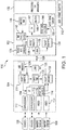
- FIG. 1 a block diagram of an exemplary architecture 100 of a multi-domain operational services system's operating in a run-time mode is shown. It should be understood that this and other arrangements described herein are set forth only as examples. Other arrangements and elements (e.g., machines, interfaces, functions, orders, and groupings of functions, etc.) can be used in addition to or instead of those shown, and some components may be omitted altogether. Further, many of the components described herein are functional entities that may be implemented as discrete or distributed components or in conjunction with other components, and in any suitable combination and location. Various functions described herein as being performed by one or more components may be carried out by hardware, firmware, and/or software. For instance, various functions may be carried out by a processor executing instructions stored in memory.
- the exemplary architecture 100 includes a control node 102 and a remote node 104.
- the architecture 100 shown in FIG. 1 is an example of an ISR platform, such as, for example, a machine vision platform.
- Typical machine vision platforms include pluralities of computing elements, operating systems, physical sensors (i.e., image forming sensors, gyros, accelerometers, GPS), application software and actuation controllers.
- a machine vision system works by querying the physical sensors at defined intervals, decoding the sensor feedback, estimating where in space the system is and where it is pointing, synchronizing the capture of the image forming data and collecting all of this information in digital memory.
- one or more application components perform each step of this data collection.
- the application software typically runs complex routines that take the image and physical sensor data to create an output.
- the active control elements of a vision system mounted on a mobile platform typically need to react to real world disturbances as detected by the wide modality of sensors.
- These machine vision systems are often challenged by deterministic behavioral needs exhibited by various components of a distributed system. The distributed nature of the system presents several challenges.
- there is a digital controller in the system that collects the sensor information and determines how to respond to this information contingent on the tasks the system intends to perform.
- the machine vision system can have a plurality of electro-mechanical actuators that need to be controlled.
- the architecture 100 should not be interpreted as having any dependency or requirement related to any single module/component or combination of modules/components illustrated therein.
- a plurality of devices 106 collect the variety of inertial and positional data related to the mobile ISR platform.
- the position, velocity, and angular orientation of the mobile ISR platform may collectively be referred to as state vector parameters.
- the state vector parameters are stored in state vector module 114 comprising a protected and managed read-write memory having a plurality of addressable memory locations.
- state vector module 114 is situated in the reconfigurable memory fabric shared by all elements of the remote node 104.
- State vector memory implemented as protected and managed multi-port random access memory (“RAM”) enables concurrent processing from the complete set of processors implemented in a particular mobile platform system.
- RAM protected and managed multi-port random access memory
- state vector module 114 further includes state management logic to perform state vector management operations for the acquired inertial and positional data.
- the state management logic coordinates sharing and updating the acquired inertial and positional data in a concurrent fashion between one or more co-processors 110 described below.
- co-processor(s) 110 may be configured to perform navigation component data acquisitions and system mobility assertion and control functions.
- co-processors 110 may be configured to actively collect auxiliary data to and from other system components, such as motor controller components and INS (Inertial Navigation System) components for instrument control purposes.
- auxiliary data encompasses such auxiliary data (including motor and status data) collected from other integrated components, such as motor controller(s).
- the one or more co-processor(s) 110 executes specific microcode instructions.
- co-processor components 110 While only two co-processor components 110 are shown in FIG. 1 for ease of illustration, alternative embodiments are contemplated in which any number and combination of co-processors 110 can be implemented within the remote node 104. This number is of course limited by the size and layout of the integrated circuit used in the remote node 104.
- co-processors 110 may operate in at least two different modes.
- these modes may include, but are not limited to, runtime and initialization modes.
- the runtime mode is an operating mode that executes instructions which may be loaded via runtime mode pathway. These instructions may include read/write commands from/to the state vector module 114. In one embodiment, these instructions may include instructions to acquire inertial and positional data at predetermined collection-time intervals from the variety of devices/sensors 106 mounted on the ISR mobile platform system 100. It is noted that the co-processors 110 facilitate data transfers between the devices 106 and the state vector module 114.
- the initialization mode may run an initialization routine (initialization code) which enables the co-processors 110 to communicate with devices 106 directly in a so-called "pass-through" mode.
- Initialization code may be generated by a high-level language compiler into the embedded system programming.
- the length of the initialization code may be substantial and, in some examples, the initialization code can be similar in length or may even substantially exceed the main code.
- the initialization code may include code used for testing, profiling, debugging, etc.
- the runtime code could be limited to simple and repetitive data flows performed in runtime operating mode, while the initialization code may include substantially complex initialization, testing and debug interfaces. Such arrangement provides more efficient resource utilization.
- the second plurality of sensors such as imaging sensors 108 is attached to one or more video pipelines 112 and comprises image sensors such as cameras, which may be configured to transmit image data via an interface format.
- the captured image data is transmitted in accordance with the interface format as a stream or packet.
- These streams can be adapted to accord with any interface format, including but not limited to the Mobile Industry Processor Interface Alliance (MIPI) CSI-2 interface format (MIPI interface format), CameraLink interface format, a USB interface format, or a Firewire interface format.
- MIPI Mobile Industry Processor Interface Alliance
- MIPI interface format MIPI interface format
- CameraLink interface format CameraLink interface format
- USB interface format a USB interface format
- Firewire interface format a Firewire interface format
- the one or more co-processors 110 may also be communicatively coupled to imaging sensors 108 and may be configured and operational to perform ingestion of high-bandwidth image data in a substantially standard manner. Furthermore, the co-processor(s) 110 are coupled with the state vector module 114 described herein.
- image data from the plurality of video pipelines 112 and/or from the plurality of imaging sensors 108 can be packetized by the co-processor(s) 110 by inserting the image data and/or additional data describing the image data into a packet in such a way that image processing components, such as for example, a video frame builder 150 hosted by the control node 102, can reconstruct images of a scene from the received image data and utilize additional system information related to the reconstructed images.
- This process of insertion of additional data describing the image data transmitted by the imaging sensors 108 is referred to hereinafter as metatagging.
- each packet of the image data may represent one line of a corresponding image.
- a line may comprise a row of pixels of a corresponding image.
- This additional data is provided by the state vector module 114.
- metadata inserted by the one or more co-processor(s) include, without limitation, earth coordinate positions of a location at which the image was taken, data indicating the geo-location coordinates for the points in the Earth-Centered Earth-Fixed and/or north/east/down coordinate system corresponding to the four corners of the image and one or more timestamps indicating when an image was taken, any detected error conditions, and the like.
- one or more line buffers 116 may be required to store information received from the plurality of video pipelines 112.
- the line buffer 116 size may be relatively large, especially for large-size images.
- a packet stripper component 118 for use in the remote node 104.
- the packet stripper component 118 comprises a receiver for receiving and processing an uplink packet.
- the packet stripper 118 extracts both a packet header 202 (shown in FIG. 2A ) and the payload data (e.g., state vector data 214) from the received uplink packet.
- the packet stripper 118 may be arranged to populate the state vector memory 114 with the state vector data 214 received from the command node 102.
- the packet stripper 118 knows which data is stored by the state vector module 114.
- the control node 102 and the remote node 104 have two independent time sources, a master time source 146 and a remote time source 120, respectively.
- a time source is any device that is capable of tracking the passage of time.
- a variety of types of time sources are contemplated herein, including a voltage-controlled temperature compensated crystal oscillator (VCTCXO), a phase locked loop oscillator, a time locked loop oscillator, a rubidium oscillator, a cesium oscillator, a trained oscillator, a microelectromechanical device (MEM), and/or other device capable of tracking the passage of time.
- a timestamp is a representation of the time indicated by a time source.
- the packet stripper 118 is configured to extract master timestamp information 208 from the header 202 of the received uplink packet and is further configured to synchronize the remote time source 120 based on the extracted master timestamp 208 information.
- the master time source 146 plays a role of a reference clock in the disclosed system.
- the remote node 104 includes a packet builder module 122.
- the packet builder module 122 is used by the remote node 104 to construct downlink packets to be written out to the control node 102.
- the downlink packets include header, state vector data and video data, as described below.
- the state vector data can be accessed from the local state vector module 114.
- the video data is populated by the packet builder module 122 by accessing one or more video line buffers 116.
- the packets generated by the packet builder module 122 can be transmitted downstream to the control node 102 through a link interface 126.
- the command node 102 and remote node 104 may be communicatively coupled by a high-speed serial link 128.
- the high-speed serial link 128 constitutes advanced communications channels that elicit multiple layers of processing and is capable of, among other things, tolerating transmission errors.
- the link interfaces 126 and 132 at the remote node 104 and control node 102, respectively may comprise any standard high-speed bidirectional point-to-point interfaces for serial link communication.
- One option is to use the "Aurora Protocol" from Xilinx (see “Aurora Protocol Specification", SP002 (v2.0) Sep. 12, 2007, which is incorporated entirely herein by reference).
- Aurora is a scalable, lightweight, link-layer protocol that can be used to move data point-to-point across one or more high-speed serial links.
- Aurora is protocol independent, and can be used to transport industry standard protocols, such as Ethernet and TCP/IP, or proprietary protocols.
- the Aurora Protocol is an open standard and is available for implementation by anyone without restriction.
- the remote node 104 includes a link manager 124 capable of managing the connection between the remote node 104 and the control node 102 of the system 100. More specifically, the link manager module 124 may be capable of configuring the link 128 and monitoring its status. As a non-limiting example, if the link manager 124 detects an error it may execute a particular error correction sequence.
- link management function may be performed by one or more processors 130.
- the control node processor(s) 130 and the link manager 124 hosted by the remote node 104 communicate with each other using link status 210, 230 and link control 212, 232 fields of the uplink packet header 202 and downlink packet header 222, respectively.
- the packet stripper module 118 upon receiving an uplink data packet extracts header information from the packet and sends link status 210 and link control 212 information to the link manager 124.
- the link manager 124 may also receive/send information from/to the link interface 126.
- the packet stripper module 138 comprises a receiver for receiving and processing a downlink packet. For example, the packet stripper 138 extracts both a packet header 222 (shown in FIG. 2B ) and the payload data (e.g., state vector data 234) from the received downlink packet.
- the packet stripper 138 may be arranged to populate local state vector memory 142 and local video line buffers 144 with both the state vector data 234 and video data 238 received from the remote node 104.
- the packet stripper module 138 may also extract header information (e.g., remote timestamp information 228) and pass it to a time synchronization module 140.
- the time synchronization module 140 may be configured to allow the control node 102 to transmit a master timestamp as part of the uplink packet, request a response from the remote node 104 and receive in response a remote timestamp 228 after a time delay corresponding to the propagation delay between the control node 102 and the remote node 104. The time synchronization module 140 may then determine the propagation delay between the control node 102 and the remote node 104. The time synchronization module 140 may then adjust the master timestamp 208 and may transmit the adjusted master timestamp 208 as part of the next uplink packet transmitted to the remote node 104. According to some embodiments, the adjusted master timestamp 208 may be further adjusted to account for the processing delay prior to transmission.
- Embodiments of the present invention provide the ISR mobile platform system 100 having a configurable data transmission rate control making it adaptable to various transmission rates. More specifically, a packet rate control module 134 is coupled to a packet builder module 136 and is configured to control transfer of uplink packets over the transmission link 128. In some embodiments, the packet rate control module 134 may include one or more bandwidth control registers. The packet rate control module 134 determines a packet speed and/or size for packets transmitted from the control node 102 to the remote node 104 over the transmission link 128. Requested packet speed and/or size are stored within bandwidth control registers. In some embodiments, data transmission rate (packet speed) depends on number of bytes to be transmitted and on bandwidth of the transmission link 128.
- a desirable data transmission rate may be a configurable parameter.
- the packet builder module 136 is used by the control node 102 to construct uplink packets to be written out to the remote node 104.
- the uplink packets include header and state vector data, as described below.
- the state vector data can be accessed from the local state vector module 142. Additionally, the master timestamp 208 is received from the time synchronization module 140.
- the packets generated by the packet builder module 136 can be transmitted upstream to the remote node 104 through the link interface 132.
- control node 102 may include a memory access conflict resolution mechanism, such as MUTEX module 148.
- MUTEX 148 is a blocking interface that enables the packet builder module 136 and the packet stripper module 138 to read/write a group of values from/to the state vector module 142.
- the video frame builder module 150 may be configured to build a frame that mimics a frame of video data (or an image) captured by one of the imaging sensors 108. For example, the video frame builder module 150 may fill in a frame with video data received from the plurality of local video line buffers 144. In other words, the video frame builder module 150 can reconstruct images of a scene from the received image data and utilize additional system information related to the reconstructed images. Such reconstructed video frames may be used for further video data processing either by the control node 102 or another node within the ISR platform.
- the computing system shown in FIG. 1 further includes multiple physically separate arrays (banks) of relatively large off chip memory.
- this memory may comprise at least one of flash memory, dynamic random access memory (DRAM), 4x DDR (dual data rate) memory, or the like.
- DRAM dynamic random access memory
- 4x DDR dual data rate
- these multiple banks of memory utilized for storage of video frame data are referred to hereinafter as DDR frame buffers 152.
- Data stored in the DDR frame buffers 152 may be used for the image processing pipeline components (not shown in FIG. 1 ).
- the image processing components may perform complex mathematical manipulation of this large size ingested data in a power efficient, deterministic manner.
- the processing circuitry of the control node 102 shown in FIG. 1 may be implemented utilizing System on Chip (SOC) technologies, while the processing circuitry of the remote node 104 may be implemented with programmable logic components (e.g. field programmable gate array (FPGA), or complex programmable logic device (CPLD)).
- processing circuitry of the remote node 104 is implemented using any number of discrete logic components.
- processing circuitry of the remote node 104 is implemented using an application specific integrated circuit (ASIC).
- ASIC application specific integrated circuit
- FIG. 2A illustrates the packet format 200 of a run-time mode uplink data packet in accordance with an embodiment of the present invention.
- the uplink data packets are sent by the control node 102 to the remote node 104 operating in a runtime mode.
- an uplink packet includes the packet header 202, the payload data (e.g., state vector data 214) and a CRC value 216.
- Each uplink packet header 202 includes a packet type field 204.
- the packet type field 204 is used to determine the packet format.
- Example packet types include but are not limited to one of the following: Command node-to-Remote node, Remote node-to-Command node, Initialization mode, Runtime mode, Retransmit and the like.
- the uplink packet header 202 for this embodiment also includes a packet index field 206.
- Each packet index field may include an index number.
- an initial index of a first transmitted uplink packet may have an index number of 1 (or any other number, as desired), and the packet index field 206 of each subsequently transmitted uplink packet may have an index number which is incremented by one relative to the index number in the index field 206 of the uplink packet transmitted previous to it.
- the uplink packet header 202 further includes a master timestamp field 208, which includes the master timestamp generated by the time synchronization module 140, as described above, and a link status field 210 which may indicate the status of the high-speed serial link 128 between the command node 102 and the remote node 104.
- the last field within the uplink packet header 202 is a link control field 212 that is used to communicate link control information such as link reset, link status query, link configuration, and the like to the link manager 124.
- the payload data 214 may include one or more state vector parameters to be transmitted to the remote node 104.
- a CRC value corresponding to an uplink packet is generated by the packet builder module 136 of the command node from the payload data 214 itself and is appended to the payload data 214.
- the integrity of the payload data 214 can be checked by the receiving packet stripper module 118 of the remote node 104 which is configured to recalculate a CRC value from the payload data 214 of the received uplink packet and configured to compare the recalculated CRC value against the appended CRC value 216 included in the received uplink packet. If there is a mismatch, the payload data 214 may have been corrupted during transmission and the remote node 104 may ask the command node 102 to retransmit the corrupted packet.
- FIG. 2B illustrates the packet format 220 of a run-time mode downlink data packet in accordance with an embodiment of the present invention.
- the downlink data packets are sent by the remote node 104 to the command node 102 operating in a runtime mode.
- the downlink data packets are sent by the remote node 102 in response to receiving corresponding uplink packets.
- the remote node 104 always responds with a downlink packet whether or not it has any data to send.
- a downlink packet includes the packet header 222, a state vector data 234, a CRC value 236 corresponding to the state vector data 234 and captured video data 238.
- the downlink packet header 222 is similar to the uplink packet header 202 and will not be described here for purposes of clarity and brevity. One noteworthy difference is that instead of the master timestamp field 208, the downlink packet header 222 includes a remote timestamp field 228.
- the remote timestamp field 228 includes a remote timestamp generated by the remote time source 120.
- the remote node 104 transmits a downlink packet in response to receiving an uplink packet from the command node 102.
- a flag 233 indicating whether the state vector data 234 included in the current packet is new data. More specifically, while building a downlink packet, the packet builder 122 of the remote node 104 checks the local state vector memory 114 to determine if any of the state vector parameters have new values. If so, such state vector values are inserted into a downlink packet and the state vector validity flag 233 is set to 1, for example. Otherwise, the state vector validity flag 233 is set 0 by the packet builder 122. Upon receiving the downlink packet, the packet stripper 138 of the command node 102 updates its local copy of the state vector data only if the state vector validity flag 233 is set to 1.
- size of the video data field 238 may vary based on transmission medium, for example.
- the video data field 238 comprises sub-header including a frame type 240, frame index 242, line size 244, as well as video line data 246 and a CRC value corresponding to the video line data field 246.
- Different types of frames may be received from the one or more video pipelines 112.
- the frame type 240 is indicated in the sub-header of the video data field 238.
- Each frame type has a number of bits associated with that frame type or (in the case of a variable length frame type) a maximum size.
- a table of these frame types may be sent periodically on the link 128 from the command node 102 to the remote node 104.
- the remote node 104 may not always have new video data to be sent.
- the frame type field 240 may be a frame validity flag 241.
- the frame validity flag 241 may be indicative of new/old video data included in the video data field 238.
- Each video frame provides a representative image as an index (e.g., frame index 242) to a set of sequential image frames.
- the line size field 244 may indicate the size of the subsequent video line data field 246.
- the video line data field includes actual line of a video image transmitted by the remote node 104 and the video line CRC value 248 is calculated based on the data contained in the video line data field 246.
- FIG. 3 is a flowchart illustrating operational steps performed by various functional components of FIG. 1 in accordance with an embodiment of the present invention.
- the flow diagram shown therein is described, by way of example, with reference to steps and/or elements shown in FIGS. 1 , 2A and 2B , although these operational steps may be carried out in any system and are not limited to the scenario shown in the aforementioned figure.
- the flow diagram in FIG. 3 illustrates an example in which operational steps are carried out in a particular order, as indicated by the lines connecting the blocks, but the various steps shown in this diagram can be performed in any order, or in any combination or sub-combination. It should be appreciated that in some embodiments some of the steps described below may be combined into a single step. In some embodiments, one or more additional steps may be included.
- the packet builder 136 of the control node 102 determines if the timer maintained by the packet rate control module 134 has triggered. This timer controls data transfer rate. As noted above, the data transfer rate may be a configurable parameter.
- the packet builder module 136 transmits an uplink packet to the remote node 104 via the link interface 132.
- the link interface 126 of the remote node 104 receives the uplink packet (step 306) and forwards it to local packet stripper module 118.
- the packet stripper module 118 extracts both header and payload information from the received uplink packet.
- data integrity is achieved by means of CRC techniques.
- the CRC technique is used for checking and detecting errors in data transmitted over a network.
- the CRC algorithm and its underlying mathematics are well known to those skilled in the art.
- the packet stripper 118 performs a CRC check when an uplink packet is received at the remote node 104.
- the CRC is calculated and compared with the CRC value 216 included in the uplink packet.
- the check is performed by the packet stripper 118 on both the header and payload portions of the received uplink packet.
- the packet stripper 118 informs the packet builder 122 to set a status flag to valid in the link status 210 field of a downlink data packet. Furthermore, in response to determining that the received packet contains valid information, the packet stripper 118 passes extracted information to other modules at the remote node 104. For example, the packet stripper 118 passes the link status 210 and link control 212 data to the link manager 124 and passes the extracted master timestamp 208 to the remote time source 120. In addition, at step 310, the packet stripper 118 writes the received state vector data 214 to the local state vector memory 114.
- the packet stripper 118 informs the packet builder 122 to set a status flag to invalid in the downlink data packet.
- the packet builder 122 receives the value of the status flag it checks the plurality of video line buffers to determine if any new video data had been received from the one or more imaging sensors 108 since the last downlink packet was sent.
- the packet builder module 122 sets the frame validity flag 241 to invalid in a downlink packet.
- the packet builder module 122 In response to determining that new video data exists (decision block 314, Yes branch), at step 316, the packet builder module 122 sets the frame validity flag 241 to valid and copies new data into the video data field 238 of the new downlink packet. Similarly, the packet builder module 122 asks the state vector module 114 if there is any new state vector data since the last transmission of the downlink packet. If there is new state vector data, the packet builder module 122 retrieves the new state vector data and inserts it into the state vector data field 234 of the new downlink packet.
- the remote time source 120 performs steps 322-326 described below.
- the remote time source 120 receives the master timestamp value 208 from the packet stripper module 118.
- the control node 102 is the one driving synchronization of the clock.
- the remote time source 120 determines if its clock is substantially in sync with the clock operating at the control node 102. If any drift detected between the two clocks, at step 324, the remote time source 120 synchronizes its clock with the clock operating at the control node 102 based on the master timestamp value 208. Once the local clock is synchronized, the remote time source 120 adds current remote timestamp 228 to the new downlink data packet.
- the packet builder 122 generates a new downlink data packet.
- generation of the new downlink packet involves generation of both all header and all payload fields of the downlink data packet 220. It should be noted that generation of the new downlink packet involves generation of CRC values 236 and 248 for the new downlink packet. It is further noted that according to the protocol contemplated by the embodiments of the present invention, the packet builder 122 generates a new downlink packet at step 318 regardless if there is any new state vector or video data to be sent to the control node. If there is no new data in the packet, the corresponding status flags will indicate that. Upon generation of the new downlink packet it is transmitted to the control node via the link interface 126 (step 320).
- the link interface 132 at the control node 102 receives the downlink packet and forwards it to local packet stripper module 138.
- the packet stripper module 138 extracts both header and payload information from the received downlink packet.
- the packet stripper module 138 performs a CRC check. In response to determining that the CRC check failed (decision block 329, No branch), at step 331, the packet stripper 138 reloads the previous transmitted uplink packet. Responsive to a determination that CRC check passed successfully (decision block 329, Yes branch), at step 330, the packet stripper module 138 determines if the status flag contained within the received downlink packet is valid.
- the packet stripper module 138 determines if the previously sent uplink packet was successfully received by the remote node. If the previously sent packet was corrupted or had any other transmission errors (decision block 330, No branch), at step 334, the packet stripper module 138 notifies the packet builder 136 to reload the previous uplink packet. Once the previous uplink packet is loaded, the packet builder 136 returns back to step 304 and retransmits it whenever the timer is triggered next time. According to an embodiment of the present invention, at step 330, the packet stripper module 134 may further determine whether the newly received downlink packet contained any new state vector and/or video data based on the other status flags 233, 241. If new data is received, the packet stripper module 134 updates state vector memory 142 and/or video line buffers 144 to make them in sync with data stored by the remote node 104.
- the packet stripper 134 passes control to the packet builder module 136, which in turn starts building a new uplink packet. For example, if there are any updates to the state vector data 142 to be sent to the remote node 104, such updates are loaded into the new uplink packet as payload data 214.
- the packet stripper 138 also extracts remote timestamp 228 from the received downlink packet and passes it to the time synchronization module 140.
- the time synchronization module 140 compares the received remote timestamp with the local time, optionally determines a propagation delay and sends the updated master timestamp to the packet builder module 136 (step 340).
- the uplink packet generated at step 336 by the packet builder module 136 includes the timestamp that should correct clock source at the remote node 104.
- FIG. 4 is a block diagram of an exemplary architecture 100 of a multi-domain operational services system's operating in an initialization mode according to embodiments of the present invention.
- the initialization mode may run an initialization routine (initialization code) which enables the co-processors 110 to communicate with devices 106 directly in a so-called "pass-through" mode.
- the initialization code may include code used for testing, profiling, debugging, and the like.
- the runtime code could be limited to simple and repetitive data flows performed in runtime operating mode, while the initialization code may include substantially complex initialization, testing and debug interfaces.
- Arrangement illustrated in FIG. 4 provides more efficient resource utilization.
- elements corresponding to the elements in FIG. 1 are referred to with the same reference numerals and a repeated description is omitted.
- both the command node 102 and the remote node 104 employ a plurality of FIFO (First In First Out) buffers 402-408 that are optimized for more efficient interaction with their respective processors. More specifically, each co-processor 110 at the remote node 104 is associated with the two FIFO blocks 402 and 404, respectively.
- the Tx (Transmit) FIFO 402a, 404a and Rx (Receive) FIFO 402b, 404b memory blocks store data in 32-bit data word blocks sufficient to buffer one or more co-processor messages, but it is envisioned that the data block size could vary depending on implementation.
- Data are stored in the Tx FIFOs 402a and 404a in the order that the data is transmitted to the Tx FIFOs 402a and 404a from the packet stripper module 118.
- the packet stripper 118 has a capability of distinguishing between data destined to each particular co-processor 110.
- the Rx FIFO memory blocks 402b and 404b store data in the order it is received from the respective co-processor 110.
- the Tx FIFOs 402a and 404a provide the stored data on demand to different co-processors 110, while the Rx FIFOs 402b and 404b provide the stored data on demand to the packet builder module 122.
- the Tx FIFOs 406a and 408a store data in the order that the data is transmitted to the Tx FIFOs 406a and 408a from the processor 130, while the Rx FIFO memory blocks 406b and 408b store data in the order it is received from the packet stripper module 138.
- the Tx FIFOs 406a and 408a at the command node 102 provide the stored data on demand to the packet builder module 136, while the Rx FIFOs 406b and 408b provide the stored data on demand to the processor 130.
- FIG. 5A illustrates the packet format 500 of an initialization mode uplink data packet in accordance with an embodiment of the present invention.
- the uplink data packets are sent by the control node 102 to the remote node 104 operating in an initialization mode.
- each co-processor may have application specific information related to a command(s) being executed by the remote node 104.
- each uplink packet in addition to having a packet header 502 may contain state vector data 504 associated with each co-processor 110 and pertaining to the application specific command(s) being sent back to the remote node 104.
- each uplink data packet (when system operates in the initialization mode) further include FIFO counter 506 and FIFO data 508 fields. It is noted that in an embodiment each FIFO field 508 can have fixed length (e.g., 12 data words). The FIFO counter 506 indicates how many of the words contained within the FIFO data field 508 are valid. The integrity of each uplink packet is verified using CRC value 510 calculated for each state vector data 504, FIFO counter 506 and FIFO field 508 blocks associated with respective co-processors 110. It should be noted that if the remote node 104 contained n number of co-processors 110, the packet fields 504-508 would be repeated n times within each packet. Each block would contain data associated with a particular co-processor.
- FIG. 5B illustrates the packet format 520 of an initialization mode downlink data packet in accordance with an embodiment of the present invention.
- the downlink data packets are sent by the remote node 104 to the control node 102 operating in an initialization mode.
- elements 524, 526, 528, 530 correspond to the elements 504, 506, 508, and 510, respectively, in FIG. 5A and a repeated description is omitted.
- various embodiments of the present invention are directed to a self-synchronized multi-domain operational system that includes a control node and a remote node.
- the messaging rate Once the messaging rate is fixed, it provides deterministic mode of operating for the system and enables determination of corresponding latencies for each exchanged message.
- the disclosed communication protocol between the command and remote nodes supports variable data rates by utilizing various flag fields described above.
- the disclosed system provides a unique mechanism for data transfer and synchronization across various platforms.
- the disclosed system facilitates a mechanism for data integrity through packet header data, packet CRC and packet re-transmit capability using particular interfaces and particular data transfer protocols.
- aspects of the present invention may be embodied as a system, method or computer program product. Accordingly, aspects of the present invention may take the form of an entirely hardware embodiment, an entirely software embodiment (including firmware, resident software, micro-code, etc.) or an embodiment combining software and hardware aspects that may all generally be referred to herein as a "circuit,” “module” or “system.” Furthermore, aspects of the present invention may take the form of a computer program product embodied in one or more computer readable medium(s) having computer readable program code embodied thereon.
- the computer readable medium may be a computer readable signal medium or a computer readable storage medium.
- a computer readable storage medium may be, for example, but not limited to, an electronic, magnetic, optical, electromagnetic, infrared, or semiconductor system, apparatus, or device, or any suitable combination of the foregoing.
- a computer readable storage medium may be any tangible medium that can contain, or store a program for use by or in connection with an instruction execution system, apparatus, or device.
- a computer readable signal medium may include a propagated data signal with computer readable program code embodied therein, for example, in baseband or as part of a carrier wave. Such a propagated signal may take any of a variety of forms, including, but not limited to, electro-magnetic, optical, or any suitable combination thereof.
- a computer readable signal medium may be any computer readable medium that is not a computer readable storage medium and that can communicate, propagate, or transport a program for use by or in connection with an instruction execution system, apparatus, or device.
- Program code embodied on a computer readable medium may be transmitted using any appropriate medium, including but not limited to wireless, wireline, optical fiber cable, RF, etc., or any suitable combination of the foregoing.
- Computer program code for carrying out operations for aspects of the present invention may be written in any combination of one or more programming languages, including an object oriented programming language such as Java, Smalltalk, C++ or the like and conventional procedural programming languages, such as the "C" programming language or similar programming languages.
- the program code may execute entirely on the user's computer, partly on the user's computer, as a stand-alone software package, partly on the user's computer and partly on a remote computer or entirely on the remote computer or server.
- the remote computer may be connected to the user's computer through any type of network, including a local area network (LAN), a wide area network (WAN) or WLAN, or the connection may be made to an external computer (for example, through the Internet using an Internet Service Provider).
- LAN local area network
- WAN wide area network
- WLAN for example, AT&T, MCI, Sprint, EarthLink, MSN, GTE, etc.
- each block in the flowchart or block diagrams may represent a module, segment, or portion of code, which comprises one or more executable instructions for implementing the specified logical function(s).
- the functions noted in the block may occur out of the order noted in the figures. For example, two blocks shown in succession may, in fact, be executed substantially concurrently, or the blocks may sometimes be executed in the reverse order, depending upon the functionality involved.
Landscapes
- Engineering & Computer Science (AREA)
- Theoretical Computer Science (AREA)
- Physics & Mathematics (AREA)
- Computer Networks & Wireless Communication (AREA)
- Signal Processing (AREA)
- General Engineering & Computer Science (AREA)
- Computer Security & Cryptography (AREA)
- General Physics & Mathematics (AREA)
- Computer Hardware Design (AREA)
- Software Systems (AREA)
- Quality & Reliability (AREA)
- Mathematical Physics (AREA)
- Probability & Statistics with Applications (AREA)
- Health & Medical Sciences (AREA)
- Bioethics (AREA)
- General Health & Medical Sciences (AREA)
- Data Exchanges In Wide-Area Networks (AREA)
Abstract
Description
- Embodiments of the present invention relate generally to field of signal processing, and specifically to data transport and time synchronization for Intelligence, Surveillance, and Reconnaissance (ISR) systems.
- ISR systems may include a plurality of sensors mounted on a plurality of airborne platforms, which can be, for example, manned or unmanned aircrafts. The sensors are used to gather information about an area of interest. Communication networks can be provided to transmit the collected image data, metadata and command and control data.
- These communication networks connect systems, such as data processors, to utilize or interact with the data moved across the network. Limitations of physical network interfaces often restrict available locations of two or more processors and other elements, limiting system's performance and/or timing synchronization procedures. Furthermore, non-standard processor configurations limit the ability to use common architectural elements, algorithms, and the like.
- It is desirable to have integrated mechanism for time synchronization and data integrity verification across corresponding platforms.
- The purpose and advantages of the illustrated embodiments will be set forth in and apparent from the description that follows. Additional advantages of the illustrated embodiments will be realized and attained by the devices, systems and methods particularly pointed out in the written description and claims hereof, as well as from the appended drawings.
- In accordance with a purpose of the illustrated embodiments, in one aspect, a multi-processor computer system for ensuring data integrity and time synchronization across a multi-domain operational platform is provided. The system includes a plurality of devices configured to acquire input data related to the multi-domain operational platform. The system further includes a remote node. The remote node includes a plurality of co-processors communicatively coupled to the plurality of devices. The plurality of co-processors are configured to control the acquisition of the input data and configured to analyze the acquired input data. The logic of the plurality of co-processors is further configured to receive a first packet from a control node. The first packet includes a packet header including at least a master timestamp, first control data and a Cyclic Redundancy Check (CRC) value associated with the first control data. The logic of the plurality of co-processors is also configured to verify integrity of the received first control data based on the received CRC value. The logic of the plurality of co-processors is further configured to generate and transmit to the control node a second packet. The second packet includes a packet header which includes at least a remote timestamp, control data, a CRC value associated with the control data and a subset of the input data. The system also includes a control node communicatively connected with the remote node via one or more high-speed serial interfaces. The control node includes one or more processors which include logic configured to receive the second packet from the remote node. The logic of the one or more processors is further configured to determine status of the first packet based on the control data included in the second packet. The logic of the one or more processors is also configured to retransmit the first packet or generate and transmit a third packet based on the determined status of the first packet. The third packet includes a packet header which includes at least a master timestamp, second control data and a CRC value associated with the second control data.
- In another aspect, a method for ensuring data integrity and time synchronization across a multi-domain operational platform is provided. The method includes receiving, at a remote node, a first packet from a control node. The first packet comprising a packet header including at least a master timestamp, first control data and a CRC value associated with the first control data. Integrity of the received first control data is verified, at the remote node, based on the received CRC data. A second packet is generated and transmitted from the remote node to the control node. The second packet including a packet header further including at least a remote timestamp, control data, a CRC value associated with the control data and a subset of the input data. The second packet is received at the control node from the remote node. Status of the first packet is determined, at the control node, based on the control data in the second packet. The first packet is retransmitted or a third packet is generated and transmitted based on the determined status of the first packet. The third packet includes a packet header further including at least a master timestamp, second control data and a CRC value associated with second control data.
- The accompanying appendices and/or drawings illustrate various, non-limiting, examples, inventive aspects in accordance with the present disclosure:
-
FIG. 1 is a block diagram of an exemplary architecture of a disclosed system operating in a run-time mode, according to embodiments of the present invention; -
FIG. 2A illustrates the packet format of a run-time mode uplink data packet, in accordance with an embodiment of the present invention; -
FIG. 2B illustrates the packet format of a run-time mode downlink data packet, in accordance with an embodiment of the present invention; -
FIG. 3 is a flowchart illustrating operational steps performed by various functional components ofFIG. 1 , in accordance with an embodiment of the present invention; -
FIG. 4 is a block diagram of an exemplary architecture of a disclosed system operating in an initialization mode, according to embodiments of the present invention; -
FIG. 5A illustrates the packet format of an initialization mode uplink data packet, in accordance with an embodiment of the present invention; -
FIG. 5B illustrates the packet format of an initialization mode downlink data packet, in accordance with an embodiment of the present invention. - The present invention is now described more fully with reference to the accompanying drawings, in which illustrated embodiments of the present invention are shown wherein like reference numerals identify like elements. The present invention is not limited in any way to the illustrated embodiments as the illustrated embodiments described below are merely exemplary of the invention, which can be embodied in various forms, as appreciated by one skilled in the art. Therefore, it is to be understood that any structural and functional details disclosed herein are not to be interpreted as limiting, but merely as a basis for the claims and as a representative for teaching one skilled in the art to variously employ the present invention. Furthermore, the terms and phrases used herein are not intended to be limiting but rather to provide an understandable description of the invention.
- Unless defined otherwise, all technical and scientific terms used herein have the same meaning as commonly understood by one of ordinary skill in the art to which this invention belongs. Although any methods and materials similar or equivalent to those described herein can also be used in the practice or testing of the present invention, exemplary methods and materials are now described. It must be noted that as used herein and in the appended claims, the singular forms "a", "an," and "the" include plural referents unless the context clearly dictates otherwise. Thus, for example, reference to "a stimulus" includes a plurality of such stimuli and reference to "the signal" includes reference to one or more signals and equivalents thereof known to those skilled in the art, and so forth.
- It is to be appreciated the embodiments of this invention as discussed below are preferably a software algorithm, program or code residing on computer useable medium having control logic for enabling execution on a machine having a computer processor. The machine typically includes memory storage configured to provide output from execution of the computer algorithm or program.
- As used herein, the term "software" is meant to be synonymous with any code or program that can be in a processor of a host computer, regardless of whether the implementation is in hardware, firmware or as a software computer product available on a disc, a memory storage device, or for download from a remote machine. The embodiments described herein include such software to implement the equations, relationships and algorithms described below. One skilled in the art will appreciate further features and advantages of the invention based on the below-described embodiments. Accordingly, the invention is not to be limited by what has been particularly shown and described, except as indicated by the appended claims.
- In exemplary embodiments, a computer system component may constitute a "module" that is configured and operates to perform certain operations as described herein below. Accordingly, the term "module" should be understood to encompass a tangible entity, be that an entity that is physically constructed, permanently configured (e.g., hardwired) or temporarily configured (e.g. programmed) to operate in a certain manner and to perform certain operations described herein.
- As used herein, the term "image" data refers to data (or a file having data) that represents an image of a physical object. The term "video" data refers to data (or a file having data) that represents a plurality of images.
- As used herein, the term "mobile platform" may refer to any vehicle with or without an on-board human pilot. For example, mobile platform may include, but are not limited to, Unmanned Aerial Vehicles (UAVs), fixed-wing UAVs, rovers, walking robots, hovercraft, submersibles, and surface vehicles, gimbaled stabilized sensor platforms and fixed image, radar platforms. The term "mobile platform" is also intended to refer to any portable electronic device such as a cellular telephone, smart phone, tablet computer, virtual reality goggle, or other suitable wireless communication device communicatively coupled to one or more sensors and running any suitable operating system. Any operable combination of the above are also considered a "mobile platform."
- The term "sensor" is used herein in a broad sense and includes any type of physical sensor or controller, such as a GPS receiver, gyroscope, accelerometer, motor controller, as well as a device for measuring temperature, current, voltage, ADC (Analog to Digital Converter), DAC (Digital to Analog Converter), Digital IO, or the like. The term "image sensor" encompasses any type of image capturing device such as a video camera, radar, LIDAR, FLIR (forward looking infrared imaging) sensor, or any combination of such sensors. The term "image sensor" is also inclusive of multi-spectral imagers and groups or arrays of the same or different image capture devices. A sensor may capture information in a series of two or three dimensional arrays. The image sensor may include both active and passive cameras.
- As used herein, the term "processor" is to be broadly construed to include any type of embedded processor.
- Embodiments of the present invention are directed to an integrated system facilitating aggregation of image data, video data, metadata and command and control data. Advantageously, the disclosed system provides a unique mechanism for data transfer and synchronization across various platforms. As yet another advantage, the disclosed system facilitates a mechanism for data integrity through packet header data, packet Cyclic Redundancy Check (CRC) and packet re-transmit capability using particular interfaces and particular data transfer protocols. Such mechanisms and protocols can be utilized for data communications in large scale computer environments that employ high speed serial links.
- With reference to
FIG. 1 , a block diagram of anexemplary architecture 100 of a multi-domain operational services system's operating in a run-time mode is shown. It should be understood that this and other arrangements described herein are set forth only as examples. Other arrangements and elements (e.g., machines, interfaces, functions, orders, and groupings of functions, etc.) can be used in addition to or instead of those shown, and some components may be omitted altogether. Further, many of the components described herein are functional entities that may be implemented as discrete or distributed components or in conjunction with other components, and in any suitable combination and location. Various functions described herein as being performed by one or more components may be carried out by hardware, firmware, and/or software. For instance, various functions may be carried out by a processor executing instructions stored in memory. - As shown in
FIG. 1 , theexemplary architecture 100 includes acontrol node 102 and aremote node 104. It should be understood that thearchitecture 100 shown inFIG. 1 is an example of an ISR platform, such as, for example, a machine vision platform. Typical machine vision platforms include pluralities of computing elements, operating systems, physical sensors (i.e., image forming sensors, gyros, accelerometers, GPS), application software and actuation controllers. In a nutshell, a machine vision system works by querying the physical sensors at defined intervals, decoding the sensor feedback, estimating where in space the system is and where it is pointing, synchronizing the capture of the image forming data and collecting all of this information in digital memory. Typically, one or more application components perform each step of this data collection. Then the application software typically runs complex routines that take the image and physical sensor data to create an output. Additionally, the active control elements of a vision system mounted on a mobile platform typically need to react to real world disturbances as detected by the wide modality of sensors. These machine vision systems are often challenged by deterministic behavioral needs exhibited by various components of a distributed system. The distributed nature of the system presents several challenges. Typically, there is a digital controller in the system that collects the sensor information and determines how to respond to this information contingent on the tasks the system intends to perform. Additionally, the machine vision system can have a plurality of electro-mechanical actuators that need to be controlled. - The
architecture 100 should not be interpreted as having any dependency or requirement related to any single module/component or combination of modules/components illustrated therein. - It is noted that a plurality of
devices 106 collect the variety of inertial and positional data related to the mobile ISR platform. In one embodiment, the position, velocity, and angular orientation of the mobile ISR platform may collectively be referred to as state vector parameters. According to an embodiment of the present invention, the state vector parameters are stored instate vector module 114 comprising a protected and managed read-write memory having a plurality of addressable memory locations. In one implementation,state vector module 114 is situated in the reconfigurable memory fabric shared by all elements of theremote node 104. State vector memory implemented as protected and managed multi-port random access memory ("RAM") enables concurrent processing from the complete set of processors implemented in a particular mobile platform system. Advantageously,state vector module 114 further includes state management logic to perform state vector management operations for the acquired inertial and positional data. According to an embodiment of the present invention, the state management logic coordinates sharing and updating the acquired inertial and positional data in a concurrent fashion between one ormore co-processors 110 described below. - In one embodiment, co-processor(s) 110 may be configured to perform navigation component data acquisitions and system mobility assertion and control functions. In addition,
co-processors 110 may be configured to actively collect auxiliary data to and from other system components, such as motor controller components and INS (Inertial Navigation System) components for instrument control purposes. For ease of discussion, the term "inertial and positional data" encompasses such auxiliary data (including motor and status data) collected from other integrated components, such as motor controller(s). In one embodiment, the one or more co-processor(s) 110 executes specific microcode instructions. - While only two
co-processor components 110 are shown inFIG. 1 for ease of illustration, alternative embodiments are contemplated in which any number and combination ofco-processors 110 can be implemented within theremote node 104. This number is of course limited by the size and layout of the integrated circuit used in theremote node 104. - It is contemplated herein that the
co-processors 110 may operate in at least two different modes. In one embodiment these modes may include, but are not limited to, runtime and initialization modes. - The runtime mode is an operating mode that executes instructions which may be loaded via runtime mode pathway. These instructions may include read/write commands from/to the
state vector module 114. In one embodiment, these instructions may include instructions to acquire inertial and positional data at predetermined collection-time intervals from the variety of devices/sensors 106 mounted on the ISRmobile platform system 100. It is noted that theco-processors 110 facilitate data transfers between thedevices 106 and thestate vector module 114. - In one embodiment, the initialization mode may run an initialization routine (initialization code) which enables the
co-processors 110 to communicate withdevices 106 directly in a so-called "pass-through" mode. Initialization code may be generated by a high-level language compiler into the embedded system programming. The length of the initialization code may be substantial and, in some examples, the initialization code can be similar in length or may even substantially exceed the main code. The initialization code may include code used for testing, profiling, debugging, etc. In other words, in an embodiment, the runtime code could be limited to simple and repetitive data flows performed in runtime operating mode, while the initialization code may include substantially complex initialization, testing and debug interfaces. Such arrangement provides more efficient resource utilization. - In a number of embodiments, the second plurality of sensors, such as
imaging sensors 108 is attached to one ormore video pipelines 112 and comprises image sensors such as cameras, which may be configured to transmit image data via an interface format. The captured image data is transmitted in accordance with the interface format as a stream or packet. These streams can be adapted to accord with any interface format, including but not limited to the Mobile Industry Processor Interface Alliance (MIPI) CSI-2 interface format (MIPI interface format), CameraLink interface format, a USB interface format, or a Firewire interface format. - In accordance with an embodiment of the present invention, the one or
more co-processors 110 may also be communicatively coupled toimaging sensors 108 and may be configured and operational to perform ingestion of high-bandwidth image data in a substantially standard manner. Furthermore, the co-processor(s) 110 are coupled with thestate vector module 114 described herein. In several embodiments, image data from the plurality ofvideo pipelines 112 and/or from the plurality ofimaging sensors 108 can be packetized by the co-processor(s) 110 by inserting the image data and/or additional data describing the image data into a packet in such a way that image processing components, such as for example, avideo frame builder 150 hosted by thecontrol node 102, can reconstruct images of a scene from the received image data and utilize additional system information related to the reconstructed images. This process of insertion of additional data describing the image data transmitted by theimaging sensors 108 is referred to hereinafter as metatagging. In one embodiment, each packet of the image data may represent one line of a corresponding image. In an embodiment of the present invention, a line may comprise a row of pixels of a corresponding image. This additional data is provided by thestate vector module 114. Examples of metadata inserted by the one or more co-processor(s) include, without limitation, earth coordinate positions of a location at which the image was taken, data indicating the geo-location coordinates for the points in the Earth-Centered Earth-Fixed and/or north/east/down coordinate system corresponding to the four corners of the image and one or more timestamps indicating when an image was taken, any detected error conditions, and the like. - When the lines in an image are processed in a particular order, one or more line buffers 116 may be required to store information received from the plurality of
video pipelines 112. Theline buffer 116 size may be relatively large, especially for large-size images. - In accordance with an embodiment of the present invention, there is provided a
packet stripper component 118 for use in theremote node 104. Thepacket stripper component 118 comprises a receiver for receiving and processing an uplink packet. For example, thepacket stripper 118 extracts both a packet header 202 (shown inFIG. 2A ) and the payload data (e.g., state vector data 214) from the received uplink packet. Thepacket stripper 118 may be arranged to populate thestate vector memory 114 with thestate vector data 214 received from thecommand node 102. Of note, thepacket stripper 118 knows which data is stored by thestate vector module 114. - In accordance with an embodiment of the present invention, the
control node 102 and theremote node 104 have two independent time sources, amaster time source 146 and aremote time source 120, respectively. A time source is any device that is capable of tracking the passage of time. A variety of types of time sources are contemplated herein, including a voltage-controlled temperature compensated crystal oscillator (VCTCXO), a phase locked loop oscillator, a time locked loop oscillator, a rubidium oscillator, a cesium oscillator, a trained oscillator, a microelectromechanical device (MEM), and/or other device capable of tracking the passage of time. A timestamp is a representation of the time indicated by a time source. - Since both video data and state vector data are time sensitive and since metatagging requires accurate timing information, it is fairly important for the ISR
mobile platform system 100 to keep themaster time source 146 and theremote time source 120 in sync. According to an embodiment of the present invention, thepacket stripper 118 is configured to extractmaster timestamp information 208 from theheader 202 of the received uplink packet and is further configured to synchronize theremote time source 120 based on the extractedmaster timestamp 208 information. In other words, themaster time source 146 plays a role of a reference clock in the disclosed system. - Further, the
remote node 104 includes apacket builder module 122. Thepacket builder module 122 is used by theremote node 104 to construct downlink packets to be written out to thecontrol node 102. The downlink packets include header, state vector data and video data, as described below. The state vector data can be accessed from the localstate vector module 114. Additionally, the video data is populated by thepacket builder module 122 by accessing one or more video line buffers 116. The packets generated by thepacket builder module 122 can be transmitted downstream to thecontrol node 102 through alink interface 126. - According to an embodiment of the present invention, the
command node 102 andremote node 104 may be communicatively coupled by a high-speedserial link 128. The high-speedserial link 128 constitutes advanced communications channels that elicit multiple layers of processing and is capable of, among other things, tolerating transmission errors. In various embodiments, the link interfaces 126 and 132 at theremote node 104 andcontrol node 102, respectively, may comprise any standard high-speed bidirectional point-to-point interfaces for serial link communication. One option is to use the "Aurora Protocol" from Xilinx (see "Aurora Protocol Specification", SP002 (v2.0) Sep. 12, 2007, which is incorporated entirely herein by reference). Aurora is a scalable, lightweight, link-layer protocol that can be used to move data point-to-point across one or more high-speed serial links. Aurora is protocol independent, and can be used to transport industry standard protocols, such as Ethernet and TCP/IP, or proprietary protocols. The Aurora Protocol is an open standard and is available for implementation by anyone without restriction. - In addition, the
remote node 104 includes alink manager 124 capable of managing the connection between theremote node 104 and thecontrol node 102 of thesystem 100. More specifically, thelink manager module 124 may be capable of configuring thelink 128 and monitoring its status. As a non-limiting example, if thelink manager 124 detects an error it may execute a particular error correction sequence. - On the
control node 102, link management function may be performed by one ormore processors 130. The control node processor(s) 130 and thelink manager 124 hosted by theremote node 104 communicate with each other usinglink status link control uplink packet header 202 anddownlink packet header 222, respectively. For example, thepacket stripper module 118 upon receiving an uplink data packet extracts header information from the packet and sendslink status 210 andlink control 212 information to thelink manager 124. As shown inFIG. 1 , thelink manager 124 may also receive/send information from/to thelink interface 126. - Still referring to the
control node 102, upon receiving the downlink packet generated by thepacket builder module 122, thelink interface 126 of theremote node 104 forwards the received packet to thepacket stripper module 138. Thepacket stripper module 138 comprises a receiver for receiving and processing a downlink packet. For example, thepacket stripper 138 extracts both a packet header 222 (shown inFIG. 2B ) and the payload data (e.g., state vector data 234) from the received downlink packet. Thepacket stripper 138 may be arranged to populate localstate vector memory 142 and local video line buffers 144 with both thestate vector data 234 andvideo data 238 received from theremote node 104. It should be noted that under normal operating conditions, copies of state vector data and video data maintained by respectivestate vector modules packet stripper module 138 may also extract header information (e.g., remote timestamp information 228) and pass it to atime synchronization module 140. - The
time synchronization module 140 may be configured to allow thecontrol node 102 to transmit a master timestamp as part of the uplink packet, request a response from theremote node 104 and receive in response aremote timestamp 228 after a time delay corresponding to the propagation delay between thecontrol node 102 and theremote node 104. Thetime synchronization module 140 may then determine the propagation delay between thecontrol node 102 and theremote node 104. Thetime synchronization module 140 may then adjust themaster timestamp 208 and may transmit the adjustedmaster timestamp 208 as part of the next uplink packet transmitted to theremote node 104. According to some embodiments, the adjustedmaster timestamp 208 may be further adjusted to account for the processing delay prior to transmission. - Embodiments of the present invention provide the ISR
mobile platform system 100 having a configurable data transmission rate control making it adaptable to various transmission rates. More specifically, a packetrate control module 134 is coupled to apacket builder module 136 and is configured to control transfer of uplink packets over thetransmission link 128. In some embodiments, the packetrate control module 134 may include one or more bandwidth control registers. The packetrate control module 134 determines a packet speed and/or size for packets transmitted from thecontrol node 102 to theremote node 104 over thetransmission link 128. Requested packet speed and/or size are stored within bandwidth control registers. In some embodiments, data transmission rate (packet speed) depends on number of bytes to be transmitted and on bandwidth of thetransmission link 128. - It should be noted that since transmitted packets control clock synchronization and since clocks in both the
remote time source 120 and themaster time source 146 are subject to drift, it is desirable to have a data transmission rate that enables clock synchronization before any significant oscillator drift occurs. Furthermore, the data transmission rate should be greater than processing rate associated with corresponding processors. A desirable data transmission rate may be a configurable parameter. - The
packet builder module 136 is used by thecontrol node 102 to construct uplink packets to be written out to theremote node 104. The uplink packets include header and state vector data, as described below. The state vector data can be accessed from the localstate vector module 142. Additionally, themaster timestamp 208 is received from thetime synchronization module 140. The packets generated by thepacket builder module 136 can be transmitted upstream to theremote node 104 through thelink interface 132. - At least in some embodiments, the
control node 102 may include a memory access conflict resolution mechanism, such asMUTEX module 148. TheMUTEX 148 is a blocking interface that enables thepacket builder module 136 and thepacket stripper module 138 to read/write a group of values from/to thestate vector module 142. - The video
frame builder module 150 may be configured to build a frame that mimics a frame of video data (or an image) captured by one of theimaging sensors 108. For example, the videoframe builder module 150 may fill in a frame with video data received from the plurality of local video line buffers 144. In other words, the videoframe builder module 150 can reconstruct images of a scene from the received image data and utilize additional system information related to the reconstructed images. Such reconstructed video frames may be used for further video data processing either by thecontrol node 102 or another node within the ISR platform. - According to an embodiment of the present invention, the computing system shown in
FIG. 1 further includes multiple physically separate arrays (banks) of relatively large off chip memory. In various embodiments this memory may comprise at least one of flash memory, dynamic random access memory (DRAM), 4x DDR (dual data rate) memory, or the like. For simplicity of discussion and illustration, these multiple banks of memory utilized for storage of video frame data are referred to hereinafter as DDR frame buffers 152. Data stored in theDDR frame buffers 152 may be used for the image processing pipeline components (not shown inFIG. 1 ). The image processing components may perform complex mathematical manipulation of this large size ingested data in a power efficient, deterministic manner. - In several embodiments, the processing circuitry of the
control node 102 shown inFIG. 1 may be implemented utilizing System on Chip (SOC) technologies, while the processing circuitry of theremote node 104 may be implemented with programmable logic components (e.g. field programmable gate array (FPGA), or complex programmable logic device (CPLD)). In another embodiment, processing circuitry of theremote node 104 is implemented using any number of discrete logic components. In yet another embodiment, the processing circuitry of theremote node 104 is implemented using an application specific integrated circuit (ASIC). -
FIG. 2A illustrates thepacket format 200 of a run-time mode uplink data packet in accordance with an embodiment of the present invention. The uplink data packets are sent by thecontrol node 102 to theremote node 104 operating in a runtime mode. According to this embodiment, an uplink packet includes thepacket header 202, the payload data (e.g., state vector data 214) and aCRC value 216. Eachuplink packet header 202 includes apacket type field 204. Thepacket type field 204 is used to determine the packet format. Example packet types include but are not limited to one of the following: Command node-to-Remote node, Remote node-to-Command node, Initialization mode, Runtime mode, Retransmit and the like. - The
uplink packet header 202 for this embodiment also includes apacket index field 206. Each packet index field may include an index number. For example, in some embodiments, an initial index of a first transmitted uplink packet may have an index number of 1 (or any other number, as desired), and thepacket index field 206 of each subsequently transmitted uplink packet may have an index number which is incremented by one relative to the index number in theindex field 206 of the uplink packet transmitted previous to it. - The
uplink packet header 202 further includes amaster timestamp field 208, which includes the master timestamp generated by thetime synchronization module 140, as described above, and alink status field 210 which may indicate the status of the high-speedserial link 128 between thecommand node 102 and theremote node 104. The last field within theuplink packet header 202 is alink control field 212 that is used to communicate link control information such as link reset, link status query, link configuration, and the like to thelink manager 124. - The
payload data 214 may include one or more state vector parameters to be transmitted to theremote node 104. Well-known schemes exist in the art to identify "bad" data or data that has otherwise been corrupted in some way. In a CRC scheme employed by an embodiment of the present invention, a CRC value corresponding to an uplink packet is generated by thepacket builder module 136 of the command node from thepayload data 214 itself and is appended to thepayload data 214. With the appendedCRC value 216, the integrity of thepayload data 214 can be checked by the receivingpacket stripper module 118 of theremote node 104 which is configured to recalculate a CRC value from thepayload data 214 of the received uplink packet and configured to compare the recalculated CRC value against the appendedCRC value 216 included in the received uplink packet. If there is a mismatch, thepayload data 214 may have been corrupted during transmission and theremote node 104 may ask thecommand node 102 to retransmit the corrupted packet. -
FIG. 2B illustrates thepacket format 220 of a run-time mode downlink data packet in accordance with an embodiment of the present invention. The downlink data packets are sent by theremote node 104 to thecommand node 102 operating in a runtime mode. The downlink data packets are sent by theremote node 102 in response to receiving corresponding uplink packets. It should be noted, that theremote node 104 always responds with a downlink packet whether or not it has any data to send. According to this embodiment, a downlink packet includes thepacket header 222, astate vector data 234, aCRC value 236 corresponding to thestate vector data 234 and capturedvideo data 238. - The
downlink packet header 222 is similar to theuplink packet header 202 and will not be described here for purposes of clarity and brevity. One noteworthy difference is that instead of themaster timestamp field 208, thedownlink packet header 222 includes aremote timestamp field 228. Theremote timestamp field 228 includes a remote timestamp generated by theremote time source 120. - As noted above, the
remote node 104 transmits a downlink packet in response to receiving an uplink packet from thecommand node 102. According to an embodiment of the present invention, at the start of thestate vector data 234 is aflag 233 indicating whether thestate vector data 234 included in the current packet is new data. More specifically, while building a downlink packet, thepacket builder 122 of theremote node 104 checks the localstate vector memory 114 to determine if any of the state vector parameters have new values. If so, such state vector values are inserted into a downlink packet and the statevector validity flag 233 is set to 1, for example. Otherwise, the statevector validity flag 233 is set 0 by thepacket builder 122. Upon receiving the downlink packet, thepacket stripper 138 of thecommand node 102 updates its local copy of the state vector data only if the statevector validity flag 233 is set to 1. - In various embodiments of the present invention, size of the
video data field 238 may vary based on transmission medium, for example. In an embodiment illustrated inFIG. 2B thevideo data field 238 comprises sub-header including aframe type 240,frame index 242,line size 244, as well asvideo line data 246 and a CRC value corresponding to the videoline data field 246. Different types of frames may be received from the one ormore video pipelines 112. Theframe type 240 is indicated in the sub-header of thevideo data field 238. Each frame type has a number of bits associated with that frame type or (in the case of a variable length frame type) a maximum size. A table of these frame types may be sent periodically on thelink 128 from thecommand node 102 to theremote node 104. Similarly to thestate vector data 234, theremote node 104 may not always have new video data to be sent. According to an embodiment of the present invention, at the start of theframe type field 240 may be aframe validity flag 241. Similarly, to the statevector validity flag 233, theframe validity flag 241 may be indicative of new/old video data included in thevideo data field 238. Each video frame provides a representative image as an index (e.g., frame index 242) to a set of sequential image frames. Theline size field 244 may indicate the size of the subsequent videoline data field 246. The video line data field includes actual line of a video image transmitted by theremote node 104 and the videoline CRC value 248 is calculated based on the data contained in the videoline data field 246. -
FIG. 3 is a flowchart illustrating operational steps performed by various functional components ofFIG. 1 in accordance with an embodiment of the present invention. Before turning to description ofFIG. 3 , it is noted that the flow diagram shown therein is described, by way of example, with reference to steps and/or elements shown inFIGS. 1 ,2A and 2B , although these operational steps may be carried out in any system and are not limited to the scenario shown in the aforementioned figure. Additionally, the flow diagram inFIG. 3 illustrates an example in which operational steps are carried out in a particular order, as indicated by the lines connecting the blocks, but the various steps shown in this diagram can be performed in any order, or in any combination or sub-combination. It should be appreciated that in some embodiments some of the steps described below may be combined into a single step. In some embodiments, one or more additional steps may be included. - According to an embodiment of the present invention, at
step 302, thepacket builder 136 of thecontrol node 102 determines if the timer maintained by the packetrate control module 134 has triggered. This timer controls data transfer rate. As noted above, the data transfer rate may be a configurable parameter. - In response to determining that the timer has triggered, at
step 304, thepacket builder module 136 transmits an uplink packet to theremote node 104 via thelink interface 132. On the other side of the high-speedserial link 128, thelink interface 126 of theremote node 104 receives the uplink packet (step 306) and forwards it to localpacket stripper module 118. Thepacket stripper module 118 extracts both header and payload information from the received uplink packet. - According to an embodiment of the present invention, data integrity is achieved by means of CRC techniques. The CRC technique is used for checking and detecting errors in data transmitted over a network. The CRC algorithm and its underlying mathematics are well known to those skilled in the art. The
packet stripper 118 performs a CRC check when an uplink packet is received at theremote node 104. Here, the CRC is calculated and compared with theCRC value 216 included in the uplink packet. The check is performed by thepacket stripper 118 on both the header and payload portions of the received uplink packet. - Responsive to a determination that CRC check passed successfully (
decision block 308, Yes branch), atstep 310, thepacket stripper 118 informs thepacket builder 122 to set a status flag to valid in thelink status 210 field of a downlink data packet. Furthermore, in response to determining that the received packet contains valid information, thepacket stripper 118 passes extracted information to other modules at theremote node 104. For example, thepacket stripper 118 passes thelink status 210 andlink control 212 data to thelink manager 124 and passes the extractedmaster timestamp 208 to theremote time source 120. In addition, atstep 310, thepacket stripper 118 writes the receivedstate vector data 214 to the localstate vector memory 114. - In response to determining that the CRC check failed (
decision block 308, No branch), atstep 312, thepacket stripper 118 informs thepacket builder 122 to set a status flag to invalid in the downlink data packet. Once thepacket builder 122 receives the value of the status flag it checks the plurality of video line buffers to determine if any new video data had been received from the one ormore imaging sensors 108 since the last downlink packet was sent. In response to determining that new video data exists (decision block 314, No branch), atstep 315, thepacket builder module 122 sets theframe validity flag 241 to invalid in a downlink packet. In response to determining that new video data exists (decision block 314, Yes branch), atstep 316, thepacket builder module 122 sets theframe validity flag 241 to valid and copies new data into thevideo data field 238 of the new downlink packet. Similarly, thepacket builder module 122 asks thestate vector module 114 if there is any new state vector data since the last transmission of the downlink packet. If there is new state vector data, thepacket builder module 122 retrieves the new state vector data and inserts it into the state vector data field 234 of the new downlink packet. - According to an embodiment of the present invention, in parallel with the steps 308-316 performed by the
packet stripper 118 andpacket builder 122 modules, theremote time source 120 performs steps 322-326 described below. Atstep 322, theremote time source 120 receives themaster timestamp value 208 from thepacket stripper module 118. As noted above, thecontrol node 102 is the one driving synchronization of the clock. In other words, theremote time source 120 determines if its clock is substantially in sync with the clock operating at thecontrol node 102. If any drift detected between the two clocks, atstep 324, theremote time source 120 synchronizes its clock with the clock operating at thecontrol node 102 based on themaster timestamp value 208. Once the local clock is synchronized, theremote time source 120 adds currentremote timestamp 228 to the new downlink data packet. - Next, at
step 318, thepacket builder 122 generates a new downlink data packet. According to an embodiment of the present invention, generation of the new downlink packet involves generation of both all header and all payload fields of thedownlink data packet 220. It should be noted that generation of the new downlink packet involves generation ofCRC values packet builder 122 generates a new downlink packet atstep 318 regardless if there is any new state vector or video data to be sent to the control node. If there is no new data in the packet, the corresponding status flags will indicate that. Upon generation of the new downlink packet it is transmitted to the control node via the link interface 126 (step 320). - At
step 328, thelink interface 132 at thecontrol node 102 receives the downlink packet and forwards it to localpacket stripper module 138. Thepacket stripper module 138 extracts both header and payload information from the received downlink packet. Atstep 329, thepacket stripper module 138 performs a CRC check. In response to determining that the CRC check failed (decision block 329, No branch), atstep 331, thepacket stripper 138 reloads the previous transmitted uplink packet. Responsive to a determination that CRC check passed successfully (decision block 329, Yes branch), atstep 330, thepacket stripper module 138 determines if the status flag contained within the received downlink packet is valid. In other words, atstep 330, thepacket stripper module 138 determines if the previously sent uplink packet was successfully received by the remote node. If the previously sent packet was corrupted or had any other transmission errors (decision block 330, No branch), at step 334, thepacket stripper module 138 notifies thepacket builder 136 to reload the previous uplink packet. Once the previous uplink packet is loaded, thepacket builder 136 returns back to step 304 and retransmits it whenever the timer is triggered next time. According to an embodiment of the present invention, atstep 330, thepacket stripper module 134 may further determine whether the newly received downlink packet contained any new state vector and/or video data based on theother status flags packet stripper module 134 updatesstate vector memory 142 and/or video line buffers 144 to make them in sync with data stored by theremote node 104. - Once all new data is extracted from the received downlink packet (if any), the
packet stripper 134 passes control to thepacket builder module 136, which in turn starts building a new uplink packet. For example, if there are any updates to thestate vector data 142 to be sent to theremote node 104, such updates are loaded into the new uplink packet aspayload data 214. - According to an embodiment of the present invention, the
packet stripper 138 also extractsremote timestamp 228 from the received downlink packet and passes it to thetime synchronization module 140. Atstep 338, thetime synchronization module 140 compares the received remote timestamp with the local time, optionally determines a propagation delay and sends the updated master timestamp to the packet builder module 136 (step 340). Accordingly, the uplink packet generated atstep 336 by thepacket builder module 136 includes the timestamp that should correct clock source at theremote node 104. Once the uplink packet is transmitted atstep 304, the cycle described above is repeated. -
FIG. 4 is a block diagram of anexemplary architecture 100 of a multi-domain operational services system's operating in an initialization mode according to embodiments of the present invention. As noted above, the initialization mode may run an initialization routine (initialization code) which enables theco-processors 110 to communicate withdevices 106 directly in a so-called "pass-through" mode. The initialization code may include code used for testing, profiling, debugging, and the like. In other words, in an embodiment, the runtime code could be limited to simple and repetitive data flows performed in runtime operating mode, while the initialization code may include substantially complex initialization, testing and debug interfaces. Arrangement illustrated inFIG. 4 provides more efficient resource utilization. InFIG. 4 , elements corresponding to the elements inFIG. 1 are referred to with the same reference numerals and a repeated description is omitted. - In this embodiment, both the
command node 102 and theremote node 104 employ a plurality of FIFO (First In First Out) buffers 402-408 that are optimized for more efficient interaction with their respective processors. More specifically, each co-processor 110 at theremote node 104 is associated with the two FIFO blocks 402 and 404, respectively. The Tx (Transmit)FIFO FIFO packet stripper module 118. According to an embodiment of the present invention, thepacket stripper 118 has a capability of distinguishing between data destined to eachparticular co-processor 110. The Rx FIFO memory blocks 402b and 404b store data in the order it is received from therespective co-processor 110. The Tx FIFOs 402a and 404a provide the stored data on demand todifferent co-processors 110, while theRx FIFOs packet builder module 122. With respect to thecontrol node 102, the Tx FIFOs 406a and 408a store data in the order that the data is transmitted to the Tx FIFOs 406a and 408a from theprocessor 130, while the Rx FIFO memory blocks 406b and 408b store data in the order it is received from thepacket stripper module 138. The Tx FIFOs 406a and 408a at thecommand node 102 provide the stored data on demand to thepacket builder module 136, while theRx FIFOs processor 130. -
FIG. 5A illustrates thepacket format 500 of an initialization mode uplink data packet in accordance with an embodiment of the present invention. The uplink data packets are sent by thecontrol node 102 to theremote node 104 operating in an initialization mode. According to an embodiment of the present invention, in addition to FIFO blocks 402-408, each co-processor may have application specific information related to a command(s) being executed by theremote node 104. Accordingly, each uplink packet in addition to having apacket header 502 may containstate vector data 504 associated with each co-processor 110 and pertaining to the application specific command(s) being sent back to theremote node 104. - As illustrated in
FIG. 5A , each uplink data packet (when system operates in the initialization mode) further includeFIFO counter 506 andFIFO data 508 fields. It is noted that in an embodiment eachFIFO field 508 can have fixed length (e.g., 12 data words). TheFIFO counter 506 indicates how many of the words contained within theFIFO data field 508 are valid. The integrity of each uplink packet is verified usingCRC value 510 calculated for eachstate vector data 504,FIFO counter 506 andFIFO field 508 blocks associated withrespective co-processors 110. It should be noted that if theremote node 104 contained n number ofco-processors 110, the packet fields 504-508 would be repeated n times within each packet. Each block would contain data associated with a particular co-processor. -
FIG. 5B illustrates thepacket format 520 of an initialization mode downlink data packet in accordance with an embodiment of the present invention. In this case, the downlink data packets are sent by theremote node 104 to thecontrol node 102 operating in an initialization mode. InFIG. 5B ,elements elements FIG. 5A and a repeated description is omitted. - In summary, various embodiments of the present invention are directed to a self-synchronized multi-domain operational system that includes a control node and a remote node. Once the messaging rate is fixed, it provides deterministic mode of operating for the system and enables determination of corresponding latencies for each exchanged message. Advantageously, the disclosed communication protocol between the command and remote nodes supports variable data rates by utilizing various flag fields described above. The disclosed system provides a unique mechanism for data transfer and synchronization across various platforms. As yet another advantage, the disclosed system facilitates a mechanism for data integrity through packet header data, packet CRC and packet re-transmit capability using particular interfaces and particular data transfer protocols.
- As will be appreciated by one skilled in the art, aspects of the present invention may be embodied as a system, method or computer program product. Accordingly, aspects of the present invention may take the form of an entirely hardware embodiment, an entirely software embodiment (including firmware, resident software, micro-code, etc.) or an embodiment combining software and hardware aspects that may all generally be referred to herein as a "circuit," "module" or "system." Furthermore, aspects of the present invention may take the form of a computer program product embodied in one or more computer readable medium(s) having computer readable program code embodied thereon.
- Any combination of one or more computer readable medium(s) may be utilized. The computer readable medium may be a computer readable signal medium or a computer readable storage medium. A computer readable storage medium may be, for example, but not limited to, an electronic, magnetic, optical, electromagnetic, infrared, or semiconductor system, apparatus, or device, or any suitable combination of the foregoing. More specific examples (a non-exhaustive list) of the computer readable storage medium would include the following: an electrical connection having one or more wires, a portable computer diskette, a hard disk, a random access memory (RAM), a read-only memory (ROM), an erasable programmable read-only memory (EPROM or Flash memory), an optical fiber, a portable compact disc read-only memory (CD-ROM), an optical storage device, a magnetic storage device, or any suitable combination of the foregoing. In the context of this document, a computer readable storage medium may be any tangible medium that can contain, or store a program for use by or in connection with an instruction execution system, apparatus, or device.
- A computer readable signal medium may include a propagated data signal with computer readable program code embodied therein, for example, in baseband or as part of a carrier wave. Such a propagated signal may take any of a variety of forms, including, but not limited to, electro-magnetic, optical, or any suitable combination thereof. A computer readable signal medium may be any computer readable medium that is not a computer readable storage medium and that can communicate, propagate, or transport a program for use by or in connection with an instruction execution system, apparatus, or device.
- Program code embodied on a computer readable medium may be transmitted using any appropriate medium, including but not limited to wireless, wireline, optical fiber cable, RF, etc., or any suitable combination of the foregoing.
- Computer program code for carrying out operations for aspects of the present invention may be written in any combination of one or more programming languages, including an object oriented programming language such as Java, Smalltalk, C++ or the like and conventional procedural programming languages, such as the "C" programming language or similar programming languages. The program code may execute entirely on the user's computer, partly on the user's computer, as a stand-alone software package, partly on the user's computer and partly on a remote computer or entirely on the remote computer or server. In the latter scenario, the remote computer may be connected to the user's computer through any type of network, including a local area network (LAN), a wide area network (WAN) or WLAN, or the connection may be made to an external computer (for example, through the Internet using an Internet Service Provider).
- The flowchart and block diagrams in the Figures illustrate the architecture, functionality, and operation of possible implementations of systems, methods and computer program products according to various embodiments of the present invention. In this regard, each block in the flowchart or block diagrams may represent a module, segment, or portion of code, which comprises one or more executable instructions for implementing the specified logical function(s). It should also be noted that, in some alternative implementations, the functions noted in the block may occur out of the order noted in the figures. For example, two blocks shown in succession may, in fact, be executed substantially concurrently, or the blocks may sometimes be executed in the reverse order, depending upon the functionality involved. It will also be noted that each block of the block diagrams and/or flowchart illustration, and combinations of blocks in the block diagrams and/or flowchart illustration, can be implemented by special purpose hardware-based systems that perform the specified functions or acts, or combinations of special purpose hardware and computer instructions.
- The descriptions of the various embodiments of the present invention have been presented for purposes of illustration, but are not intended to be exhaustive or limited to the embodiments disclosed. Many modifications and variations will be apparent to those of ordinary skill in the art without departing from the scope and spirit of the described embodiments. The terminology used herein was chosen to best explain the principles of the embodiments, the practical application or technical improvement over technologies found in the marketplace, or to enable others of ordinary skill in the art to understand the embodiments disclosed herein.
Claims (15)
- A multi-processor computer system for ensuring data integrity and time synchronization across a multi-domain operational platform, the computer system comprising:a plurality of devices (106) configured to acquire input data related to the multi-domain operational platform;a remote node (104) comprising:
a plurality of co-processors (110) communicatively coupled to the plurality of devices (106), the plurality of co-processors including logic configured to:control acquisition of the input data and analyze the acquired input data;receive a first packet from a control node (102), the first packet comprising a packet header including at least a master timestamp, first control data and a Cyclic Redundancy Check (CRC) value associated with the first control data;verify integrity of the received first control data based on the received CRC data; andgenerate and transmit to the control node (102) a second packet, the second packet comprising a packet header including at least a remote timestamp, control data, a CRC value associated with the control data and a subset of the input data; anda control node (102) communicatively connected with the remote node via one or more high- speed serial interfaces, the control node (102) comprising:
one or more processors including logic configured to:receive the second packet from the remote node (104);determine status of the first packet based on the control data in the second packet; andretransmit the first packet or generate and transmit a third packet based on the determined status of the first packet, the third packet comprising a packet header including at least a master timestamp, second control data and a CRC value associated with the second control data. - The system of claim 1, wherein the input data comprises at least one of: inertial data, positional data, and video data related to the multi-domain operational platform.
- The system of claim 1 or 2, wherein the packet header of the first packet and the second packet further includes packet type, packet index, link status and link control information, and optionally wherein the control node (102) is further configured to perform one or more link management functions using the link status and the link control information.
- The system of claim 2, wherein the remote node (104) further comprises one or more buffers configured to store the received video data, wherein the hardware logic of the remote node is further configured to determine whether the one or more buffers contain new video data and wherein the subset of the input data includes the new video data.
- The system of any preceding claim, wherein the one or more high-speed serial interfaces use Aurora protocol.
- The system of claim 4, wherein the new video data comprises frame type information, frame index information, video line size information, video information and a CRC value associated with the video information.
- The system of claim 6, wherein the frame type information includes a flag indicative of frame validity, or
wherein the hardware logic of the control node is further configured to generate one or more video frames based on the received new video data. - The system of any preceding claim, wherein the hardware logic of the control node is further configured to synchronize the master timestamp and the remote timestamp, or
wherein the one or more processors and the plurality of co-processors are configured to operate in one of initialization mode and run-time mode. - A method for ensuring data integrity and time synchronization across a multi-domain operational platform, the method comprising steps of:receiving, at a remote node (104), a first packet from a control node (102), the first packet comprising a packet header including at least a master timestamp, first control data and a CRC value associated with the first control data;verifying, at the remote node, integrity of the received first control data based on the received CRC data;generating and transmitting from the remote node to the control node (102) a second packet, the second packet comprising a packet header including at least a remote timestamp, control data, a CRC value associated with the control data and a subset of the input data;receiving, at the control node (102), the second packet from the remote node;determining, at the control node (102), status of the first packet based on the control data in the second packet; andretransmitting the first packet or generating and transmitting a third packet based on the determined status of the first packet, the third packet comprising a packet header including at least a master timestamp, second control data and a CRC value associated with the second control data.
- The method of claim 9, wherein the input data comprises at least one of: inertial data, positional data, and video data related to the multi-domain operational platform.
- The method of claim 9 or 10, wherein the packet header of the first packet and the second packet further includes packet type, packet index, link status and link control information, and optionally further comprising performing, at the control node (102), one or more link management functions using the link status and the link control information.
- The method of claim 10, wherein the remote node (104) comprises one or more buffers configured to store the received video data, wherein the method further comprises determining, at the remote node, whether the one or more buffers contains new video data and wherein the subset of the input data includes the new video data.
- The method of any of claims 9 to 12, wherein the one or more high-speed serial interfaces use Aurora protocol.
- The method of claim 12, wherein the new video data comprises frame type information, frame index information, video line size information, video information and a CRC value associated with the video information, and optionally
wherein the frame type information includes a flag indicative of frame validity. - The method of any of claims 9 to 14, further comprising synchronizing, at the control node (102), the master timestamp and the remote timestamp.
Applications Claiming Priority (1)
| Application Number | Priority Date | Filing Date | Title |
|---|---|---|---|
| US16/013,609 US10411793B1 (en) | 2018-06-20 | 2018-06-20 | Data transport and time synchronization for ISR systems |
Publications (2)
| Publication Number | Publication Date |
|---|---|
| EP3584965A1 true EP3584965A1 (en) | 2019-12-25 |
| EP3584965B1 EP3584965B1 (en) | 2023-07-26 |
Family
ID=67220620
Family Applications (1)
| Application Number | Title | Priority Date | Filing Date |
|---|---|---|---|
| EP19180994.6A Active EP3584965B1 (en) | 2018-06-20 | 2019-06-18 | Data transport and time synchronization for isr systems |
Country Status (2)
| Country | Link |
|---|---|
| US (2) | US10411793B1 (en) |
| EP (1) | EP3584965B1 (en) |
Families Citing this family (8)
| Publication number | Priority date | Publication date | Assignee | Title |
|---|---|---|---|---|
| US10411793B1 (en) * | 2018-06-20 | 2019-09-10 | Goodrich Corporation | Data transport and time synchronization for ISR systems |
| BE1027084B1 (en) * | 2019-02-28 | 2020-09-28 | Constell8 | UNIT FOR CONTROLLING DATA COMMUNICATION |
| GB201911378D0 (en) * | 2019-08-08 | 2019-09-25 | Hoptroff Richard George | System for timestamping events on edge devices |
| US11360505B2 (en) | 2020-02-11 | 2022-06-14 | Simmonds Precision Products, Inc. | Distributed network time synchronization |
| CN111371524B (en) * | 2020-03-12 | 2021-08-03 | 中国科学院长春光学精密机械与物理研究所 | Time synchronization accuracy detection system based on cameralink protocol |
| CN112214065B (en) | 2020-09-17 | 2022-10-21 | 北京普源精电科技有限公司 | Equipment synchronization calibration method, device, equipment and storage medium |
| CN113722250B (en) * | 2021-09-15 | 2024-09-27 | 南京全信传输科技股份有限公司 | Aurora protocol-based double-path redundant data exchange method and system |
| US12145741B2 (en) | 2022-06-01 | 2024-11-19 | Arinc Incorporated | Onboard equipment data synchronization system |
Citations (2)
| Publication number | Priority date | Publication date | Assignee | Title |
|---|---|---|---|---|
| US20100054244A1 (en) * | 2008-09-02 | 2010-03-04 | Fujitsu Limited | Time sychronization method and relay apparatus |
| US20140226984A1 (en) * | 2009-11-10 | 2014-08-14 | Calix, Inc. | Transparent clock for precision timing distribution |
Family Cites Families (12)
| Publication number | Priority date | Publication date | Assignee | Title |
|---|---|---|---|---|
| US7120170B2 (en) * | 2001-12-20 | 2006-10-10 | Motorola, Inc. | Method and apparatus for the time synchronization in a data communication system |
| US7961828B2 (en) * | 2004-10-06 | 2011-06-14 | Motorola Mobility, Inc. | Sync bursts frequency offset compensation |
| US7764713B2 (en) * | 2005-09-28 | 2010-07-27 | Avaya Inc. | Synchronization watermarking in multimedia streams |
| US8855846B2 (en) | 2005-10-20 | 2014-10-07 | Jason W. Grzywna | System and method for onboard vision processing |
| US9182228B2 (en) | 2006-02-13 | 2015-11-10 | Sony Corporation | Multi-lens array system and method |
| GB2459602B (en) | 2007-02-21 | 2011-09-21 | Pixel Velocity Inc | Scalable system for wide area surveillance |
| US8677920B1 (en) | 2007-08-30 | 2014-03-25 | Ocom Technology LLC | Underwater vehicle |
| CN101453316B (en) * | 2007-11-30 | 2011-04-13 | 华为技术有限公司 | Time information synchronization system, method and related apparatus |
| IL201682A0 (en) | 2009-10-22 | 2010-11-30 | Bluebird Aero Systems Ltd | Imaging system for uav |
| US9866339B1 (en) * | 2013-10-24 | 2018-01-09 | Marvell Israel (M.I.S.L) Ltd. | Method and apparatus for securing clock synchronization in a network |
| US9760114B1 (en) * | 2014-01-03 | 2017-09-12 | Juniper Networks, Inc. | Systems and methods for improving clock synchronization between master and slave devices |
| US10411793B1 (en) * | 2018-06-20 | 2019-09-10 | Goodrich Corporation | Data transport and time synchronization for ISR systems |
-
2018
- 2018-06-20 US US16/013,609 patent/US10411793B1/en active Active
-
2019
- 2019-06-18 EP EP19180994.6A patent/EP3584965B1/en active Active
- 2019-09-09 US US16/565,195 patent/US10911135B2/en active Active
Patent Citations (2)
| Publication number | Priority date | Publication date | Assignee | Title |
|---|---|---|---|---|
| US20100054244A1 (en) * | 2008-09-02 | 2010-03-04 | Fujitsu Limited | Time sychronization method and relay apparatus |
| US20140226984A1 (en) * | 2009-11-10 | 2014-08-14 | Calix, Inc. | Transparent clock for precision timing distribution |
Non-Patent Citations (2)
| Title |
|---|
| AURORA PROTOCOL SPECIFICATION, vol. 2.0, 12 September 2007 (2007-09-12), pages SP002 |
| YANG JUN ET AL: "Space Time Protocol Based on IEEE1588", 2015 10TH INTERNATIONAL CONFERENCE ON BROADBAND AND WIRELESS COMPUTING, COMMUNICATION AND APPLICATIONS (BWCCA), IEEE, 4 November 2015 (2015-11-04), pages 359 - 363, XP032876550, DOI: 10.1109/BWCCA.2015.61 * |
Also Published As
| Publication number | Publication date |
|---|---|
| EP3584965B1 (en) | 2023-07-26 |
| US10411793B1 (en) | 2019-09-10 |
| US10911135B2 (en) | 2021-02-02 |
| US20190393953A1 (en) | 2019-12-26 |
Similar Documents
| Publication | Publication Date | Title |
|---|---|---|
| US10911135B2 (en) | Data transport and time synchronization for ISR systems | |
| EP3098566B1 (en) | System architecture for machine vision on moving platforms | |
| EP3096234B1 (en) | Control systems state vector management using co-processing and multiport ram | |
| US11408736B2 (en) | Master control system for satellite image processing | |
| US11070732B2 (en) | Method for image processing, device, unmanned aerial vehicle, and receiver | |
| EP3101876B1 (en) | Parallel caching architecture and methods for block-based data processing | |
| US8543263B2 (en) | Distributed avionics | |
| US11201859B2 (en) | Tenant-specific encryption of packets carried in multi-cloud networks | |
| CN109104259A (en) | A kind of multisensor clock synchronization synchronization system and method | |
| WO2008063446A1 (en) | Methods and systems for relaying data packets | |
| EP2927771A1 (en) | Flying drone trajectory synchronization | |
| CN111279637B (en) | Information synchronization method, unmanned aerial vehicle, load device, system and storage medium | |
| CN109506656A (en) | Restoring method is passed under a kind of in-orbit posture information of high-precision | |
| Chin et al. | Keck adaptive optics facility: real time controller upgrade | |
| US12463916B2 (en) | Communication apparatus, control method for communication apparatus, and storage medium | |
| US10761741B1 (en) | Method and system for managing and sharing data using smart pointers | |
| Hofer et al. | Circular frame buffer to enhance map synchronization in edge assisted SLAM | |
| US11818329B1 (en) | Synchronizing stereoscopic cameras using padding data setting modification | |
| US11770518B1 (en) | Detecting stereoscopic camera desynchronization | |
| KR20230068761A (en) | Method and apparatus for acquiring stereo images based on multiple unmanned aerial vehicles | |
| CN116156143B (en) | Data generation methods, camera equipment, head-mounted display devices, and readable media | |
| US12401490B2 (en) | Communication device and communication method | |
| KR20210066042A (en) | Drone based aerial photography measurement device | |
| Meier | Dynamic Robot Architecture for Robust Realtime Computer Vision | |
| Roumage et al. | The Ingenuity Mars Helicopter Specified and Analyzed with the Real-time Mode-aware Dataflow Model |
Legal Events
| Date | Code | Title | Description |
|---|---|---|---|
| PUAI | Public reference made under article 153(3) epc to a published international application that has entered the european phase |
Free format text: ORIGINAL CODE: 0009012 |
|
| STAA | Information on the status of an ep patent application or granted ep patent |
Free format text: STATUS: THE APPLICATION HAS BEEN PUBLISHED |
|
| AK | Designated contracting states |
Kind code of ref document: A1 Designated state(s): AL AT BE BG CH CY CZ DE DK EE ES FI FR GB GR HR HU IE IS IT LI LT LU LV MC MK MT NL NO PL PT RO RS SE SI SK SM TR |
|
| AX | Request for extension of the european patent |
Extension state: BA ME |
|
| STAA | Information on the status of an ep patent application or granted ep patent |
Free format text: STATUS: REQUEST FOR EXAMINATION WAS MADE |
|
| 17P | Request for examination filed |
Effective date: 20200625 |
|
| RBV | Designated contracting states (corrected) |
Designated state(s): AL AT BE BG CH CY CZ DE DK EE ES FI FR GB GR HR HU IE IS IT LI LT LU LV MC MK MT NL NO PL PT RO RS SE SI SK SM TR |
|
| STAA | Information on the status of an ep patent application or granted ep patent |
Free format text: STATUS: EXAMINATION IS IN PROGRESS |
|
| 17Q | First examination report despatched |
Effective date: 20200921 |
|
| REG | Reference to a national code |
Ref country code: DE Ipc: G06F0021720000 Ref country code: DE Ref legal event code: R079 Ref document number: 602019033390 Country of ref document: DE Free format text: PREVIOUS MAIN CLASS: H04J0003060000 Ipc: G06F0021720000 |
|
| GRAP | Despatch of communication of intention to grant a patent |
Free format text: ORIGINAL CODE: EPIDOSNIGR1 |
|
| STAA | Information on the status of an ep patent application or granted ep patent |
Free format text: STATUS: GRANT OF PATENT IS INTENDED |
|
| RIC1 | Information provided on ipc code assigned before grant |
Ipc: H04L 1/00 20060101ALI20220721BHEP Ipc: H03M 13/09 20060101ALI20220721BHEP Ipc: G06F 21/64 20130101ALI20220721BHEP Ipc: G06F 11/10 20060101ALI20220721BHEP Ipc: H04J 3/06 20060101ALI20220721BHEP Ipc: H04B 7/185 20060101ALI20220721BHEP Ipc: H04B 7/212 20060101ALI20220721BHEP Ipc: G06F 21/72 20130101AFI20220721BHEP |
|
| INTG | Intention to grant announced |
Effective date: 20220823 |
|
| GRAJ | Information related to disapproval of communication of intention to grant by the applicant or resumption of examination proceedings by the epo deleted |
Free format text: ORIGINAL CODE: EPIDOSDIGR1 |
|
| STAA | Information on the status of an ep patent application or granted ep patent |
Free format text: STATUS: EXAMINATION IS IN PROGRESS |
|
| GRAP | Despatch of communication of intention to grant a patent |
Free format text: ORIGINAL CODE: EPIDOSNIGR1 |
|
| STAA | Information on the status of an ep patent application or granted ep patent |
Free format text: STATUS: GRANT OF PATENT IS INTENDED |
|
| INTC | Intention to grant announced (deleted) | ||
| INTG | Intention to grant announced |
Effective date: 20230131 |
|
| RIN1 | Information on inventor provided before grant (corrected) |
Inventor name: JAROK, JONATHAN C. Inventor name: RICCI, LOUIS Inventor name: RAMSEY, SCOTT W. |
|
| GRAS | Grant fee paid |
Free format text: ORIGINAL CODE: EPIDOSNIGR3 |
|
| GRAA | (expected) grant |
Free format text: ORIGINAL CODE: 0009210 |
|
| STAA | Information on the status of an ep patent application or granted ep patent |
Free format text: STATUS: THE PATENT HAS BEEN GRANTED |
|
| AK | Designated contracting states |
Kind code of ref document: B1 Designated state(s): AL AT BE BG CH CY CZ DE DK EE ES FI FR GB GR HR HU IE IS IT LI LT LU LV MC MK MT NL NO PL PT RO RS SE SI SK SM TR |
|
| REG | Reference to a national code |
Ref country code: CH Ref legal event code: EP |
|
| REG | Reference to a national code |
Ref country code: IE Ref legal event code: FG4D |
|
| REG | Reference to a national code |
Ref country code: DE Ref legal event code: R096 Ref document number: 602019033390 Country of ref document: DE |
|
| P01 | Opt-out of the competence of the unified patent court (upc) registered |
Effective date: 20230922 |
|
| REG | Reference to a national code |
Ref country code: LT Ref legal event code: MG9D |
|
| REG | Reference to a national code |
Ref country code: NL Ref legal event code: MP Effective date: 20230726 |
|
| REG | Reference to a national code |
Ref country code: AT Ref legal event code: MK05 Ref document number: 1592775 Country of ref document: AT Kind code of ref document: T Effective date: 20230726 |
|
| PG25 | Lapsed in a contracting state [announced via postgrant information from national office to epo] |
Ref country code: NL Free format text: LAPSE BECAUSE OF FAILURE TO SUBMIT A TRANSLATION OF THE DESCRIPTION OR TO PAY THE FEE WITHIN THE PRESCRIBED TIME-LIMIT Effective date: 20230726 |
|
| PG25 | Lapsed in a contracting state [announced via postgrant information from national office to epo] |
Ref country code: GR Free format text: LAPSE BECAUSE OF FAILURE TO SUBMIT A TRANSLATION OF THE DESCRIPTION OR TO PAY THE FEE WITHIN THE PRESCRIBED TIME-LIMIT Effective date: 20231027 |
|
| PG25 | Lapsed in a contracting state [announced via postgrant information from national office to epo] |
Ref country code: IS Free format text: LAPSE BECAUSE OF FAILURE TO SUBMIT A TRANSLATION OF THE DESCRIPTION OR TO PAY THE FEE WITHIN THE PRESCRIBED TIME-LIMIT Effective date: 20231126 |
|
| PG25 | Lapsed in a contracting state [announced via postgrant information from national office to epo] |
Ref country code: SE Free format text: LAPSE BECAUSE OF FAILURE TO SUBMIT A TRANSLATION OF THE DESCRIPTION OR TO PAY THE FEE WITHIN THE PRESCRIBED TIME-LIMIT Effective date: 20230726 Ref country code: RS Free format text: LAPSE BECAUSE OF FAILURE TO SUBMIT A TRANSLATION OF THE DESCRIPTION OR TO PAY THE FEE WITHIN THE PRESCRIBED TIME-LIMIT Effective date: 20230726 Ref country code: PT Free format text: LAPSE BECAUSE OF FAILURE TO SUBMIT A TRANSLATION OF THE DESCRIPTION OR TO PAY THE FEE WITHIN THE PRESCRIBED TIME-LIMIT Effective date: 20231127 Ref country code: NO Free format text: LAPSE BECAUSE OF FAILURE TO SUBMIT A TRANSLATION OF THE DESCRIPTION OR TO PAY THE FEE WITHIN THE PRESCRIBED TIME-LIMIT Effective date: 20231026 Ref country code: LV Free format text: LAPSE BECAUSE OF FAILURE TO SUBMIT A TRANSLATION OF THE DESCRIPTION OR TO PAY THE FEE WITHIN THE PRESCRIBED TIME-LIMIT Effective date: 20230726 Ref country code: LT Free format text: LAPSE BECAUSE OF FAILURE TO SUBMIT A TRANSLATION OF THE DESCRIPTION OR TO PAY THE FEE WITHIN THE PRESCRIBED TIME-LIMIT Effective date: 20230726 Ref country code: IS Free format text: LAPSE BECAUSE OF FAILURE TO SUBMIT A TRANSLATION OF THE DESCRIPTION OR TO PAY THE FEE WITHIN THE PRESCRIBED TIME-LIMIT Effective date: 20231126 Ref country code: HR Free format text: LAPSE BECAUSE OF FAILURE TO SUBMIT A TRANSLATION OF THE DESCRIPTION OR TO PAY THE FEE WITHIN THE PRESCRIBED TIME-LIMIT Effective date: 20230726 Ref country code: GR Free format text: LAPSE BECAUSE OF FAILURE TO SUBMIT A TRANSLATION OF THE DESCRIPTION OR TO PAY THE FEE WITHIN THE PRESCRIBED TIME-LIMIT Effective date: 20231027 Ref country code: FI Free format text: LAPSE BECAUSE OF FAILURE TO SUBMIT A TRANSLATION OF THE DESCRIPTION OR TO PAY THE FEE WITHIN THE PRESCRIBED TIME-LIMIT Effective date: 20230726 Ref country code: AT Free format text: LAPSE BECAUSE OF FAILURE TO SUBMIT A TRANSLATION OF THE DESCRIPTION OR TO PAY THE FEE WITHIN THE PRESCRIBED TIME-LIMIT Effective date: 20230726 |
|
| PG25 | Lapsed in a contracting state [announced via postgrant information from national office to epo] |
Ref country code: PL Free format text: LAPSE BECAUSE OF FAILURE TO SUBMIT A TRANSLATION OF THE DESCRIPTION OR TO PAY THE FEE WITHIN THE PRESCRIBED TIME-LIMIT Effective date: 20230726 |
|
| PG25 | Lapsed in a contracting state [announced via postgrant information from national office to epo] |
Ref country code: ES Free format text: LAPSE BECAUSE OF FAILURE TO SUBMIT A TRANSLATION OF THE DESCRIPTION OR TO PAY THE FEE WITHIN THE PRESCRIBED TIME-LIMIT Effective date: 20230726 |
|
| REG | Reference to a national code |
Ref country code: DE Ref legal event code: R097 Ref document number: 602019033390 Country of ref document: DE |
|
| PG25 | Lapsed in a contracting state [announced via postgrant information from national office to epo] |
Ref country code: SM Free format text: LAPSE BECAUSE OF FAILURE TO SUBMIT A TRANSLATION OF THE DESCRIPTION OR TO PAY THE FEE WITHIN THE PRESCRIBED TIME-LIMIT Effective date: 20230726 Ref country code: RO Free format text: LAPSE BECAUSE OF FAILURE TO SUBMIT A TRANSLATION OF THE DESCRIPTION OR TO PAY THE FEE WITHIN THE PRESCRIBED TIME-LIMIT Effective date: 20230726 Ref country code: ES Free format text: LAPSE BECAUSE OF FAILURE TO SUBMIT A TRANSLATION OF THE DESCRIPTION OR TO PAY THE FEE WITHIN THE PRESCRIBED TIME-LIMIT Effective date: 20230726 Ref country code: EE Free format text: LAPSE BECAUSE OF FAILURE TO SUBMIT A TRANSLATION OF THE DESCRIPTION OR TO PAY THE FEE WITHIN THE PRESCRIBED TIME-LIMIT Effective date: 20230726 Ref country code: DK Free format text: LAPSE BECAUSE OF FAILURE TO SUBMIT A TRANSLATION OF THE DESCRIPTION OR TO PAY THE FEE WITHIN THE PRESCRIBED TIME-LIMIT Effective date: 20230726 Ref country code: CZ Free format text: LAPSE BECAUSE OF FAILURE TO SUBMIT A TRANSLATION OF THE DESCRIPTION OR TO PAY THE FEE WITHIN THE PRESCRIBED TIME-LIMIT Effective date: 20230726 Ref country code: SK Free format text: LAPSE BECAUSE OF FAILURE TO SUBMIT A TRANSLATION OF THE DESCRIPTION OR TO PAY THE FEE WITHIN THE PRESCRIBED TIME-LIMIT Effective date: 20230726 |
|
| PG25 | Lapsed in a contracting state [announced via postgrant information from national office to epo] |
Ref country code: IT Free format text: LAPSE BECAUSE OF FAILURE TO SUBMIT A TRANSLATION OF THE DESCRIPTION OR TO PAY THE FEE WITHIN THE PRESCRIBED TIME-LIMIT Effective date: 20230726 |
|
| PLBE | No opposition filed within time limit |
Free format text: ORIGINAL CODE: 0009261 |
|
| STAA | Information on the status of an ep patent application or granted ep patent |
Free format text: STATUS: NO OPPOSITION FILED WITHIN TIME LIMIT |
|
| 26N | No opposition filed |
Effective date: 20240429 |
|
| PG25 | Lapsed in a contracting state [announced via postgrant information from national office to epo] |
Ref country code: SI Free format text: LAPSE BECAUSE OF FAILURE TO SUBMIT A TRANSLATION OF THE DESCRIPTION OR TO PAY THE FEE WITHIN THE PRESCRIBED TIME-LIMIT Effective date: 20230726 |
|
| PG25 | Lapsed in a contracting state [announced via postgrant information from national office to epo] |
Ref country code: BG Free format text: LAPSE BECAUSE OF FAILURE TO SUBMIT A TRANSLATION OF THE DESCRIPTION OR TO PAY THE FEE WITHIN THE PRESCRIBED TIME-LIMIT Effective date: 20230726 |
|
| PG25 | Lapsed in a contracting state [announced via postgrant information from national office to epo] |
Ref country code: BG Free format text: LAPSE BECAUSE OF FAILURE TO SUBMIT A TRANSLATION OF THE DESCRIPTION OR TO PAY THE FEE WITHIN THE PRESCRIBED TIME-LIMIT Effective date: 20230726 |
|
| PG25 | Lapsed in a contracting state [announced via postgrant information from national office to epo] |
Ref country code: MC Free format text: LAPSE BECAUSE OF FAILURE TO SUBMIT A TRANSLATION OF THE DESCRIPTION OR TO PAY THE FEE WITHIN THE PRESCRIBED TIME-LIMIT Effective date: 20230726 |
|
| REG | Reference to a national code |
Ref country code: CH Ref legal event code: PL |
|
| PG25 | Lapsed in a contracting state [announced via postgrant information from national office to epo] |
Ref country code: LU Free format text: LAPSE BECAUSE OF NON-PAYMENT OF DUE FEES Effective date: 20240618 |
|
| PG25 | Lapsed in a contracting state [announced via postgrant information from national office to epo] |
Ref country code: IE Free format text: LAPSE BECAUSE OF NON-PAYMENT OF DUE FEES Effective date: 20240618 |
|
| PG25 | Lapsed in a contracting state [announced via postgrant information from national office to epo] |
Ref country code: CH Free format text: LAPSE BECAUSE OF NON-PAYMENT OF DUE FEES Effective date: 20240630 Ref country code: BE Free format text: LAPSE BECAUSE OF NON-PAYMENT OF DUE FEES Effective date: 20240630 |
|
| REG | Reference to a national code |
Ref country code: BE Ref legal event code: MM Effective date: 20240630 |
|
| PGFP | Annual fee paid to national office [announced via postgrant information from national office to epo] |
Ref country code: DE Payment date: 20250520 Year of fee payment: 7 |
|
| PGFP | Annual fee paid to national office [announced via postgrant information from national office to epo] |
Ref country code: GB Payment date: 20250520 Year of fee payment: 7 |
|
| PGFP | Annual fee paid to national office [announced via postgrant information from national office to epo] |
Ref country code: FR Payment date: 20250521 Year of fee payment: 7 |
|
| PG25 | Lapsed in a contracting state [announced via postgrant information from national office to epo] |
Ref country code: CY Free format text: LAPSE BECAUSE OF FAILURE TO SUBMIT A TRANSLATION OF THE DESCRIPTION OR TO PAY THE FEE WITHIN THE PRESCRIBED TIME-LIMIT; INVALID AB INITIO Effective date: 20190618 |
|
| PG25 | Lapsed in a contracting state [announced via postgrant information from national office to epo] |
Ref country code: HU Free format text: LAPSE BECAUSE OF FAILURE TO SUBMIT A TRANSLATION OF THE DESCRIPTION OR TO PAY THE FEE WITHIN THE PRESCRIBED TIME-LIMIT; INVALID AB INITIO Effective date: 20190618 |