EP3584903A1 - Dc voltage control in renewable energy-based multilevel power converter - Google Patents
Dc voltage control in renewable energy-based multilevel power converter Download PDFInfo
- Publication number
- EP3584903A1 EP3584903A1 EP19181206.4A EP19181206A EP3584903A1 EP 3584903 A1 EP3584903 A1 EP 3584903A1 EP 19181206 A EP19181206 A EP 19181206A EP 3584903 A1 EP3584903 A1 EP 3584903A1
- Authority
- EP
- European Patent Office
- Prior art keywords
- bus
- power
- converter
- low
- coupled
- Prior art date
- Legal status (The legal status is an assumption and is not a legal conclusion. Google has not performed a legal analysis and makes no representation as to the accuracy of the status listed.)
- Pending
Links
Images



Classifications
-
- H—ELECTRICITY
- H02—GENERATION; CONVERSION OR DISTRIBUTION OF ELECTRIC POWER
- H02J—ELECTRIC POWER NETWORKS; CIRCUIT ARRANGEMENTS OR SYSTEMS FOR SUPPLYING OR DISTRIBUTING ELECTRIC POWER; SYSTEMS FOR STORING ELECTRIC ENERGY
- H02J7/00—Circuit arrangements for charging or discharging batteries or for supplying loads from batteries
- H02J7/34—Parallel operation in networks using both storage and other DC sources, e.g. providing buffering
- H02J7/35—Parallel operation in networks using both storage and other DC sources, e.g. providing buffering with light sensitive cells
-
- H—ELECTRICITY
- H02—GENERATION; CONVERSION OR DISTRIBUTION OF ELECTRIC POWER
- H02J—ELECTRIC POWER NETWORKS; CIRCUIT ARRANGEMENTS OR SYSTEMS FOR SUPPLYING OR DISTRIBUTING ELECTRIC POWER; SYSTEMS FOR STORING ELECTRIC ENERGY
- H02J3/00—Circuit arrangements for AC mains or AC distribution networks
- H02J3/38—Arrangements for feeding a single network from two or more generators or sources in parallel; Arrangements for feeding already energised networks from additional generators or sources in parallel
- H02J3/381—Dispersed generators
-
- H—ELECTRICITY
- H02—GENERATION; CONVERSION OR DISTRIBUTION OF ELECTRIC POWER
- H02M—APPARATUS FOR CONVERSION BETWEEN AC AND AC, BETWEEN AC AND DC, OR BETWEEN DC AND DC, AND FOR USE WITH MAINS OR SIMILAR POWER SUPPLY SYSTEMS; CONVERSION OF DC OR AC INPUT POWER INTO SURGE OUTPUT POWER; CONTROL OR REGULATION THEREOF
- H02M1/00—Details of apparatus for conversion
- H02M1/10—Arrangements incorporating converting means for enabling loads to be operated at will from different kinds of power supplies, e.g. from AC or DC
-
- H—ELECTRICITY
- H02—GENERATION; CONVERSION OR DISTRIBUTION OF ELECTRIC POWER
- H02M—APPARATUS FOR CONVERSION BETWEEN AC AND AC, BETWEEN AC AND DC, OR BETWEEN DC AND DC, AND FOR USE WITH MAINS OR SIMILAR POWER SUPPLY SYSTEMS; CONVERSION OF DC OR AC INPUT POWER INTO SURGE OUTPUT POWER; CONTROL OR REGULATION THEREOF
- H02M3/00—Conversion of DC power input into DC power output
- H02M3/02—Conversion of DC power input into DC power output without intermediate conversion into AC
- H02M3/04—Conversion of DC power input into DC power output without intermediate conversion into AC by static converters
- H02M3/06—Conversion of DC power input into DC power output without intermediate conversion into AC by static converters using resistors or capacitors, e.g. potential divider
- H02M3/07—Conversion of DC power input into DC power output without intermediate conversion into AC by static converters using resistors or capacitors, e.g. potential divider using capacitors charged and discharged alternately by semiconductor devices with control electrode, e.g. charge pumps
-
- H—ELECTRICITY
- H02—GENERATION; CONVERSION OR DISTRIBUTION OF ELECTRIC POWER
- H02M—APPARATUS FOR CONVERSION BETWEEN AC AND AC, BETWEEN AC AND DC, OR BETWEEN DC AND DC, AND FOR USE WITH MAINS OR SIMILAR POWER SUPPLY SYSTEMS; CONVERSION OF DC OR AC INPUT POWER INTO SURGE OUTPUT POWER; CONTROL OR REGULATION THEREOF
- H02M3/00—Conversion of DC power input into DC power output
- H02M3/02—Conversion of DC power input into DC power output without intermediate conversion into AC
- H02M3/04—Conversion of DC power input into DC power output without intermediate conversion into AC by static converters
- H02M3/10—Conversion of DC power input into DC power output without intermediate conversion into AC by static converters using discharge tubes with control electrode or semiconductor devices with control electrode
-
- H—ELECTRICITY
- H02—GENERATION; CONVERSION OR DISTRIBUTION OF ELECTRIC POWER
- H02M—APPARATUS FOR CONVERSION BETWEEN AC AND AC, BETWEEN AC AND DC, OR BETWEEN DC AND DC, AND FOR USE WITH MAINS OR SIMILAR POWER SUPPLY SYSTEMS; CONVERSION OF DC OR AC INPUT POWER INTO SURGE OUTPUT POWER; CONTROL OR REGULATION THEREOF
- H02M3/00—Conversion of DC power input into DC power output
- H02M3/02—Conversion of DC power input into DC power output without intermediate conversion into AC
- H02M3/04—Conversion of DC power input into DC power output without intermediate conversion into AC by static converters
- H02M3/10—Conversion of DC power input into DC power output without intermediate conversion into AC by static converters using discharge tubes with control electrode or semiconductor devices with control electrode
- H02M3/145—Conversion of DC power input into DC power output without intermediate conversion into AC by static converters using discharge tubes with control electrode or semiconductor devices with control electrode using devices of a triode or transistor type requiring continuous application of a control signal
- H02M3/155—Conversion of DC power input into DC power output without intermediate conversion into AC by static converters using discharge tubes with control electrode or semiconductor devices with control electrode using devices of a triode or transistor type requiring continuous application of a control signal using semiconductor devices only
- H02M3/156—Conversion of DC power input into DC power output without intermediate conversion into AC by static converters using discharge tubes with control electrode or semiconductor devices with control electrode using devices of a triode or transistor type requiring continuous application of a control signal using semiconductor devices only with automatic control of output voltage or current, e.g. switching regulators
- H02M3/158—Conversion of DC power input into DC power output without intermediate conversion into AC by static converters using discharge tubes with control electrode or semiconductor devices with control electrode using devices of a triode or transistor type requiring continuous application of a control signal using semiconductor devices only with automatic control of output voltage or current, e.g. switching regulators including plural semiconductor devices as final control devices for a single load
-
- H—ELECTRICITY
- H02—GENERATION; CONVERSION OR DISTRIBUTION OF ELECTRIC POWER
- H02M—APPARATUS FOR CONVERSION BETWEEN AC AND AC, BETWEEN AC AND DC, OR BETWEEN DC AND DC, AND FOR USE WITH MAINS OR SIMILAR POWER SUPPLY SYSTEMS; CONVERSION OF DC OR AC INPUT POWER INTO SURGE OUTPUT POWER; CONTROL OR REGULATION THEREOF
- H02M7/00—Conversion of AC power input into DC power output; Conversion of DC power input into AC power output
- H02M7/02—Conversion of AC power input into DC power output without possibility of reversal
- H02M7/04—Conversion of AC power input into DC power output without possibility of reversal by static converters
- H02M7/12—Conversion of AC power input into DC power output without possibility of reversal by static converters using discharge tubes with control electrode or semiconductor devices with control electrode
- H02M7/21—Conversion of AC power input into DC power output without possibility of reversal by static converters using discharge tubes with control electrode or semiconductor devices with control electrode using devices of a triode or transistor type requiring continuous application of a control signal
- H02M7/217—Conversion of AC power input into DC power output without possibility of reversal by static converters using discharge tubes with control electrode or semiconductor devices with control electrode using devices of a triode or transistor type requiring continuous application of a control signal using semiconductor devices only
-
- H—ELECTRICITY
- H02—GENERATION; CONVERSION OR DISTRIBUTION OF ELECTRIC POWER
- H02M—APPARATUS FOR CONVERSION BETWEEN AC AND AC, BETWEEN AC AND DC, OR BETWEEN DC AND DC, AND FOR USE WITH MAINS OR SIMILAR POWER SUPPLY SYSTEMS; CONVERSION OF DC OR AC INPUT POWER INTO SURGE OUTPUT POWER; CONTROL OR REGULATION THEREOF
- H02M7/00—Conversion of AC power input into DC power output; Conversion of DC power input into AC power output
- H02M7/42—Conversion of DC power input into AC power output without possibility of reversal
- H02M7/44—Conversion of DC power input into AC power output without possibility of reversal by static converters
- H02M7/48—Conversion of DC power input into AC power output without possibility of reversal by static converters using discharge tubes with control electrode or semiconductor devices with control electrode
- H02M7/483—Converters with outputs that each can have more than two voltages levels
- H02M7/487—Neutral point clamped inverters
-
- H—ELECTRICITY
- H02—GENERATION; CONVERSION OR DISTRIBUTION OF ELECTRIC POWER
- H02M—APPARATUS FOR CONVERSION BETWEEN AC AND AC, BETWEEN AC AND DC, OR BETWEEN DC AND DC, AND FOR USE WITH MAINS OR SIMILAR POWER SUPPLY SYSTEMS; CONVERSION OF DC OR AC INPUT POWER INTO SURGE OUTPUT POWER; CONTROL OR REGULATION THEREOF
- H02M7/00—Conversion of AC power input into DC power output; Conversion of DC power input into AC power output
- H02M7/42—Conversion of DC power input into AC power output without possibility of reversal
- H02M7/44—Conversion of DC power input into AC power output without possibility of reversal by static converters
- H02M7/48—Conversion of DC power input into AC power output without possibility of reversal by static converters using discharge tubes with control electrode or semiconductor devices with control electrode
- H02M7/53—Conversion of DC power input into AC power output without possibility of reversal by static converters using discharge tubes with control electrode or semiconductor devices with control electrode using devices of a triode or transistor type requiring continuous application of a control signal
- H02M7/537—Conversion of DC power input into AC power output without possibility of reversal by static converters using discharge tubes with control electrode or semiconductor devices with control electrode using devices of a triode or transistor type requiring continuous application of a control signal using semiconductor devices only, e.g. single switched pulse inverters
-
- H—ELECTRICITY
- H02—GENERATION; CONVERSION OR DISTRIBUTION OF ELECTRIC POWER
- H02S—GENERATION OF ELECTRIC POWER BY CONVERSION OF INFRARED RADIATION, VISIBLE LIGHT OR ULTRAVIOLET LIGHT, e.g. USING PHOTOVOLTAIC [PV] MODULES
- H02S40/00—Components or accessories in combination with PV modules, not provided for in groups H02S10/00 - H02S30/00
- H02S40/30—Electrical components
- H02S40/32—Electrical components comprising DC/AC inverter means associated with the PV module itself, e.g. AC modules
-
- H—ELECTRICITY
- H02—GENERATION; CONVERSION OR DISTRIBUTION OF ELECTRIC POWER
- H02J—ELECTRIC POWER NETWORKS; CIRCUIT ARRANGEMENTS OR SYSTEMS FOR SUPPLYING OR DISTRIBUTING ELECTRIC POWER; SYSTEMS FOR STORING ELECTRIC ENERGY
- H02J2101/00—Supply or distribution of decentralised, dispersed or local electric power generation
- H02J2101/20—Dispersed power generation using renewable energy sources
- H02J2101/22—Solar energy
- H02J2101/24—Photovoltaics
-
- H—ELECTRICITY
- H02—GENERATION; CONVERSION OR DISTRIBUTION OF ELECTRIC POWER
- H02J—ELECTRIC POWER NETWORKS; CIRCUIT ARRANGEMENTS OR SYSTEMS FOR SUPPLYING OR DISTRIBUTING ELECTRIC POWER; SYSTEMS FOR STORING ELECTRIC ENERGY
- H02J2105/00—Networks for supplying or distributing electric power characterised by their spatial reach or by the load
- H02J2105/10—Local stationary networks having a local or delimited stationary reach
- H02J2105/16—Local stationary networks having a local or delimited stationary reach being internal to power sources or power generation plants
-
- H—ELECTRICITY
- H02—GENERATION; CONVERSION OR DISTRIBUTION OF ELECTRIC POWER
- H02J—ELECTRIC POWER NETWORKS; CIRCUIT ARRANGEMENTS OR SYSTEMS FOR SUPPLYING OR DISTRIBUTING ELECTRIC POWER; SYSTEMS FOR STORING ELECTRIC ENERGY
- H02J7/00—Circuit arrangements for charging or discharging batteries or for supplying loads from batteries
- H02J7/34—Parallel operation in networks using both storage and other DC sources, e.g. providing buffering
-
- H—ELECTRICITY
- H02—GENERATION; CONVERSION OR DISTRIBUTION OF ELECTRIC POWER
- H02M—APPARATUS FOR CONVERSION BETWEEN AC AND AC, BETWEEN AC AND DC, OR BETWEEN DC AND DC, AND FOR USE WITH MAINS OR SIMILAR POWER SUPPLY SYSTEMS; CONVERSION OF DC OR AC INPUT POWER INTO SURGE OUTPUT POWER; CONTROL OR REGULATION THEREOF
- H02M1/00—Details of apparatus for conversion
- H02M1/0067—Converter structures employing plural converter units, other than for parallel operation of the units on a single load
-
- Y—GENERAL TAGGING OF NEW TECHNOLOGICAL DEVELOPMENTS; GENERAL TAGGING OF CROSS-SECTIONAL TECHNOLOGIES SPANNING OVER SEVERAL SECTIONS OF THE IPC; TECHNICAL SUBJECTS COVERED BY FORMER USPC CROSS-REFERENCE ART COLLECTIONS [XRACs] AND DIGESTS
- Y02—TECHNOLOGIES OR APPLICATIONS FOR MITIGATION OR ADAPTATION AGAINST CLIMATE CHANGE
- Y02E—REDUCTION OF GREENHOUSE GAS [GHG] EMISSIONS, RELATED TO ENERGY GENERATION, TRANSMISSION OR DISTRIBUTION
- Y02E10/00—Energy generation through renewable energy sources
- Y02E10/50—Photovoltaic [PV] energy
- Y02E10/56—Power conversion systems, e.g. maximum power point trackers
Definitions
- At least one example in accordance with the present invention relates generally to renewable energy-based multilevel power converters.
- PV Photovoltaic
- a renewable energy-based power converter comprising an input configured to be coupled to a renewable energy-based power source and to receive input DC power having an input DC voltage level, a high-side DC bus, a low-side DC bus, a first output configured to be coupled to an AC grid, an inverter portion coupled to the high-side DC bus and the low-side DC bus and configured to convert DC power from the high-side DC bus and the low-side DC bus into output AC power and provide the output AC power to the first output, an interface converter coupled to the high-side DC bus and the low-side DC bus, a first auxiliary DC-DC converter coupled to the interface converter and configured to be coupled to a first DC load, and a controller coupled to the interface converter, wherein, in a first mode of operation, the high-side DC bus and the low-side DC bus are configured to receive the input DC power from the input, and the controller is configured to operate the interface converter to convert DC power from the high-side DC bus and the low-side DC bus into
- the renewable energy-based power converter further comprises a neutral point, a high-side capacitor coupled between the high-side DC bus and the neutral point; and a low-side capacitor coupled between the low-side DC bus and the neutral point, wherein in operating the interface converter to balance the first voltage level on the high-side DC bus with the second voltage level on the low-side DC bus, the controller is further configured to operate the interface converter to balance the first voltage level across the high-side capacitor with the second voltage level across the low-side capacitor.
- the controller in operating the interface converter to balance the first voltage level across the high-side capacitor and the second voltage level across the low-side capacitor, is further configured to operate the interface converter to load at least one of the high-side DC bus and the low-side DC bus with resistance.
- the renewable energy-based power converter further comprises a second auxiliary DC-DC converter coupled to the interface converter and configured to be coupled to a second DC load, wherein, in the first mode of operation, the controller is further configured to operate the second auxiliary DC-DC converter to convert the regulated DC power into second output DC power provided to the second DC load.
- the renewable energy-based power converter further comprises an input switch coupled to the input, wherein the controller is further configured, in the first mode of operation, to operate the input switch to couple the input to the high-side DC bus and the low-side DC bus.
- the renewable energy-based power converter further comprises an auxiliary AC-DC converter coupled to the first output and the interface converter, wherein, in a second mode of operation, the controller is further configured to operate the input switch to decouple the input from the high-side DC bus and the low-side DC bus, to operate the auxiliary AC-DC converter to convert AC power from the AC grid into the regulated DC power having the regulated DC voltage level, to operate the interface converter to convert the regulated DC power into DC bus power to charge the high-side capacitor and the low-side capacitor, and to operate the interface converter to balance the first voltage level across the high-side capacitor and the second voltage level across the low-side capacitor.
- the controller is further configured to operate in the second mode of operation prior to operating in the first mode of operation.
- the renewable energy-based power converter further comprises an output switch coupled between the inverter portion and the first output, wherein the controller is further configured to operate the output switch to decouple the first output from the inverter portion in the second mode of operation and to couple the first output to the inverter in the first mode of operation.
- the renewable energy-based power converter further comprises an Electric Energy Storage (EES) device coupled to the interface converter and the first auxiliary DC-DC converter.
- EES Electric Energy Storage
- the renewable energy-based power converter further comprises a second output coupled to the inverter portion and configured to be coupled to an AC load, wherein the inverter portion is further configured to provide the output AC power to the AC load via the second output.
- the interface converter includes a non-isolated bi-directional converter. In another embodiment, the interface converter includes an isolated bi-directional converter.
- Another apect in accord with the present invention is directed to a method for operating a renewable energy-based power converter including an input configured to be coupled to a renewable energy-based power source , a high-side DC bus, a low-side DC bus, and an output configured to be coupled to an AC grid, wherein the method comprises receiving, at the input, input DC power from the renewable energy-based power source, providing, in a first mode of operation, the input DC power to the high-side DC bus and the low-side DC bus, converting, in the first mode of operation with an inverter portion, DC power from the high-side DC bus and the low-side DC bus into output AC power, providing, in the first mode of operation, DC power from the high-side DC bus and the low-side DC bus to an interface converter, converting, in the first mode of operation with the interface converter, DC power from the high-side DC bus and the low-side DC bus into regulated DC power having a regulated DC voltage level, converting, in the first mode of operation with a first auxiliary DC-
- the renewable energy-based power converter further includes a neutral point, a high-side capacitor coupled between the high-side DC bus and the neutral point, and a low-side capacitor coupled between the low-side DC bus and the neutral point, and balancing includes balancing the voltage level across the high-side capacitor with the voltage level across the low-side capacitor.
- balancing further includes loading at least one of the high-side DC bus and the low-side DC bus with a virtual resistance.
- the method further comprises converting, in the first mode of operation with a second auxiliary DC-DC converter, the regulated DC power into second output DC power, and providing the second output DC power to a second DC load.
- the method further comprises decoupling, in a second mode of operation, the input from the high-side DC bus and the low-side DC bus, converting, in the second mode of operation with an auxiliary AC-DC converter, AC power from the AC grid into the regulated DC power having the regulated DC voltage level, converting, in the second mode of operation with the interface converter, the regulated DC power into DC bus power, charging, with the DC bus power, the high-side capacitor and the low-side capacitor, and balancing, in the second mode of operation, the first voltage level across the high-side capacitor and the second voltage level across the low-side capacitor.
- the method further comprises coupling, in the first mode of operation, the input to the high-side DC bus and the low-side DC bus, wherein decoupling, in the second mode of operation, is performed prior to coupling, in the first mode of operation.
- At least one aspect in accord with the present invention is directed to a renewable energy-based power converter comprising an input configured to be coupled to a renewable energy-based power source and to receive input DC power having an input DC voltage level, a high-side DC bus, a low-side DC bus, a neutral point, a high-side capacitor coupled between the high-side DC bus and the neutral point, a low-side capacitor coupled between the low-side DC bus and the neutral point, an output configured to be coupled to an AC grid, an inverter portion coupled to the high-side DC bus and the low-side DC bus and configured to operate to convert DC power from the high-side DC bus and the low-side DC bus into output AC power and provide the output AC power to the output, and means for providing regulated DC power, derived from the input DC power, to at least one DC subsystem, for balancing a first voltage level on the high-side DC bus with a second voltage level on the low-side DC bus, and for pre-charging, prior to operating the inverter portion to convert DC power from the high
- references to "or” may be construed as inclusive so that any terms described using “or” may indicate any of a single, more than one, and all of the described terms.
- the term usage in the incorporated features is supplementary to that of this document; for irreconcilable differences, the term usage in this document controls.
- PV inverters are commonly utilized to convert the DC output of a PV solar panel into an AC output that can be fed into an electrical grid or used by a local, off-grid, electrical network.
- a PV inverter is coupled directly to an electrical grid (e.g., utility grid) and AC power generated by the PV inverter (based on DC power received from a PV solar panel) is provided to the grid.
- AC power from the grid can also be drawn by the PV inverter.
- At least one conventional topology for a PV inverter includes a split DC bus where it is generally desirable to balance DC voltage between the two DC busses and limit inrush transients to avoid electrical stress and potentially irreversible damage to components of the inverter.
- One common approach for DC bus balancing in a PV inverter is to utilize resistive-type dissipative elements when the inverter is in an inactive mode. However, such elements can be relatively expensive, inefficient, and limited in capability.
- traditional power converters typically include a power system that provides required power to different subsystems (e.g., a Digital Signal Processor (DSP), microcontroller, fan, control and communication systems, gate driver, etc.) of the power converter.
- DSP Digital Signal Processor
- a split-bus renewable energy-based multilevel converter e.g., a PV inverter as described above
- High voltage power components can be utilized in a PV inverter to handle the conversion; however, such components are expensive and do not provide voltage balancing/current transient mitigation functions.
- a power converter architecture is provided herein that integrates DC voltage balancing and power supply features for renewable energy-based multilevel power converters.
- the architecture provides a control structure that performs both DC balancing at an input port and voltage regulation at an output port.
- the architecture can also operate a pre-charge function for start-up initializing conditions to reduce inrush current and operate to reduce DC ripple for higher DC-bus voltage utilization.
- FIG. 1 is a block diagram of a multilevel power converter 100 (i.e., a PV inverter) according to aspects described herein.
- the PV inverter 100 includes an input 102, an input switch (Kdc) 104, a first EMI inductor 106, a second EMI inductor 107, a high-side bus 108, a low-side bus 110, an inverter portion 112, an output switch 114, a first output 116, a second output 118, an interface converter (3LIC) 120, a first auxiliary DC-DC converter 122, a second auxiliary DC-DC converter 124, an auxiliary AC-DC converter 126, a neutral point (NP) 128, a high-side capacitor 130, a low-side capacitor 132, and a controller 140.
- Kdc input switch
- the first auxiliary DC-DC converter 122 and the second auxiliary DC-DC converter 124 are isolated converters (e.g., a flyback or forward converter); however, in other embodiments, the first auxiliary DC-DC converter 122 and the second auxiliary DC-DC converter 124 are different types of converters.
- the input switch 104 is a relay; however, in other embodiments, the input switch 104 can be some other type of switch.
- the inverter portion is a 3-level neutral-point clamped (NPC) inverter; however, in other embodiments, a different type of inverter may be utilized.
- NPC neutral-point clamped
- the input 102 is configured to be coupled to a Photovoltaic (PV) Array.
- the PV Array may be coupled to an Electric Energy Storage (EES) device 103.
- the input is selectively coupled to the first EMI inductor 106 and the second EMI inductor 107 via the input switch 104.
- the high-side bus 108 is coupled to the input switch 104 via the first EMI inductor 106.
- the low-side bus 110 is coupled to the input switch 104 via the second EMI inductor 107.
- the high-side capacitor 130 is coupled between the high-side bus 108 and the neutral point 128.
- the low-side capacitor 132 is coupled between the low-side bus 110 and the neutral point 128.
- the inverter is coupled to the high-side bus 108, the low-side bus 110, the second output 118, and the output switch 114.
- the output switch is also coupled to the first output 116.
- the interface converter 120 is coupled to the neutral point 128, the high-side bus 108, and the low-side bus 110.
- the interface converter 120 includes a high-side interface 111 coupled to the high-side bus 108 and a low-side interface 113 coupled to the low-side bus 110.
- the interface converter 120 is further coupled to the first auxiliary DC-DC converter 122, the second auxiliary DC-DC converter 124, and the auxiliary AC-DC converter 126.
- the first auxiliary DC-DC converter 122 is configured to be coupled to a first DC load123.
- the second auxiliary DC-DC converter 124 is configured to be coupled to a second DC load 125.
- the AC-DC converter 126 is also coupled to the first output 116.
- the first output 116 is configured to be coupled to an AC grid 134.
- the second output 118 is configured to be coupled to at least one AC load.
- an EES device 136 e.g., a mini-EES system
- the controller 140 is coupled to different components of the system 100 and is configured to transmit control signals to different components of the system 100,
- the PV array 101 provides input DC power to the input 102.
- the input voltage ( V in ) of the input DC power provided to the input 102 varies within a 500-2000V range; however, in other embodiments, the DC power provided to the input 102 is configured differently.
- the input DC power is provided to the inverter 112 via the closed input switch 105, the first and second EMI inductors 106, 107, and the high-side and low-side busses 108, 110.
- the controller 140 operates the inverter 112 (e.g., switches of the inverter 112) to convert the DC power received from the busses 108, 110 into output AC power.
- the output AC power can be provided to at least one AC load coupled to the second output 188 and the AC grid 134 coupled to the first output 116 (via the closed output switch 114).
- the output AC power is 3-phase AC power; however, in other embodiments, the output AC power can be configured differently.
- the interface converter 120 can also receive the input DC power from the input 102 via the closed input switch 105 and the first and second EMI inductors 106, 107.
- the interface converter 120 converts the input DC power into regulated DC power having a regulated voltage level ( V a ) and provides the regulated DC power to the first auxiliary DC-DC converter 122 and the second auxiliary DC-DC converter 124.
- V a regulated voltage level
- Each of the first auxiliary DC-DC converter 122 and the second auxiliary DC-DC converter 124 can convert the regulated DC power into output DC power and provide the output DC power to a corresponding DC load 123, 125 (e.g., internal loads such as cooling fans, micro-processor control boards, a communication interface, a power device gate driver, etc.).
- Each of the first auxiliary DC-DC converter 122 and the second auxiliary DC-DC converter 124 can also convert DC power from the EES device 136 into the output DC power.
- the auxiliary AC-DC converter 126 can receive input AC power from the AC grid 134 (e.g., if DC power from the interface converter 120 or EES device 136 is unavailable), convert the input AC power into the output DC power and provide the output DC power to the first auxiliary DC-DC converter 122 and the second auxiliary DC-DC converter 124.
- Different operational modes of the system 100 are described in greater detail below.
- the interface converter 120 can also perform voltage balancing with voltage regulation across the high-side capacitor 130 and the low-side capacitor 132.
- a typical performance index for a power conversion system is DC bus voltage utilization.
- a wider input DC voltage range for a PV inverter can allow higher energy harvesting.
- the neutral point (NP) is typically compensated under all modes of operating: converter stand-by, power conversion with active, reactive power, and with different power factor (PF) conditions.
- the 3-phase 3-level DC bus capacitance can be described by the following dynamics (with response to the system 100 of FIG.
- the control of the interface converter e.g., by the controller 140
- An increase in DC-bus voltage utilization of the system 100 can be achieved by reducing, through the DC bus voltage balancing described above, the neutral point (NP) 128 voltage deviation.
- k p is the proportional gain (i.e., it sets the bandwidth and stability phase margin)
- k r is the resonant gain (at a selected resonant frequency) of the neutral point (NP) 128 voltage regulator.
- the high gain of the regulator can allow the regulator to eliminate the steady-state error in the closed loop for the selected frequency of operation.
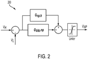
- the neutral point (NP) 128 voltage regulator 200 can be utilized to extend DC bus utilization by damping sinusoidal harmonics contained in the DC bus voltages ( V H and V L ).
- the interface converter 120 can also operate in a DC precharge and power balancing mode of operation.
- DC precharge can be performed at start-up, prior to power conversion being performed on power received from the PV array 101 (i.e., by the inverter 100).
- the input switch (Kdc) 104 when the input switch (Kdc) 104 is closed, an inrush current transient can occur between the power source (e.g., the PV array 101, the electrical energy storage device 102) and the DC bus coupled capacitors (i.e., the high-side capacitor 130 and the low side capacitor 132).
- the inrush current can degrade the performance and lifetime of the input switch (Kdc) 104 and the capacitors 130, 132.
- This negative effect can be eliminated by pre-charging the capacitors 130, 132 to a voltage level regulated by the interface converter 120.
- the voltage applied to the capacitors 130, 132 can be controlled and balanced to avoid damage or over-stress to the capacitors 130, 132 during the pre-charge process. This can extend the lifetime of the capacitors 130, 132 and the input switch (Kdc) 104 and/or allow for the use of lower quality switches.
- the interface converter 120 is interfaced between the capacitors 130, 132 and the internal auxiliary power converters (i.e., the first auxiliary DC-DC converter 122, the second auxiliary DC-DC converter 124, and the auxiliary AC-DC converter 126).
- the auxiliary AC-DC converter 126 converts the AC grid power into DC power provided to the first auxiliary DC-DC converter 122, the second auxiliary DC-DC converter 124, and the interface converter 120, and regulates the voltage level ( V a ) of the DC power to a desired level (e.g., 400V).
- the interface converter 120 converts the DC power at the V a voltage level to DC power at a DC bus voltage level ( V dc ) .
- the interface converter 120 converts the DC power by pre-charging the high-side capacitor 130 and the low-side capacitor 132 and satisfying the following condition: ⁇ V H ⁇ V L V dc ⁇ ⁇ 1 1 ⁇ V dc V in ⁇ ⁇ 2 , where a 1 , a 2 are the specified design limits (e.g. 1%) to achieve the desired regulation voltage level.
- the input switch (Kdc) 104 can be closed and inrush current can be eliminated since the DC bus voltage level ( V dc ) is the same in magnitude with input voltage ( V in ).
- the output switch 114 can be closed and the system 100 is ready to convert energy (e.g., from the PV array 101/EES device 103 to the outputs 116, 118).
- DC precharge can also be performed when the DC input source (e.g., the PV array 101/EES device 103) is absent and AC grid reactive power compensation is desired.
- the DC input source e.g., the PV array 101/EES device 103
- AC grid reactive power compensation is desired.
- the output switch 114 is turned on, an inrush current can occur between the AC grid 134 (i.e., the first output 116) and the bus capacitors (130, 132).
- the inrush current may damage or degrade the performance and lifetime of the output switch 114, the bus capacitors 130, 132, and/or the diodes of the inverter portion 112. This negative effect can be eliminated by pre-charging the capacitors 130, 132.
- the auxiliary AC-DC converter 126 converts the AC grid power into DC power provided to the first auxiliary DC-DC converter 122, the second auxiliary DC-DC converter 124, and the interface converter 120, and regulates the voltage level ( V a ) of the DC power to a desired level (e.g., 400V).
- the interface converter 120 converts the DC power at the V a voltage level to DC power at a DC bus voltage level ( V dc ) .
- the interface converter 120 converts the DC power by pre-charging the high-side capacitor 130 and the low-side capacitor 132 and satisfying the following condition: ⁇ V H ⁇ V L V dc ⁇ ⁇ 1 1 ⁇ V dc V LN 6 ⁇ ⁇ 3 , where a 1 , a 3 are the specified design limits (e.g. 1%) to achieve the desired voltage regulation.
- a 1 , a 3 are the specified design limits (e.g. 1%) to achieve the desired voltage regulation.
- an EES device 136 (e.g., a mini-EES system) can be coupled to the interface converter 120, the first auxiliary DC-DC converter 122, the second auxiliary DC-DC converter 124, and the auxiliary AC-DC converter 126.
- Such an EES device 136 can provide enhanced functionality, particularly when the input 102 is connected to the PV array 101.
- the EES device 136 can be configured to complement the PV array 101 based power conversion. More specifically, transient cloud fields traditionally cause variability in PV energy production and the impact of a sudden change in PV power production (e.g., due to a cloud) can impact AC grid stability. Accordingly, the EES device 136 can be configured to smooth the PV array 101 production and enhance grid stability.
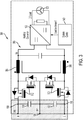
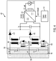
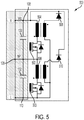
- FIGS. 3-5 include more detailed schematic diagrams of different embodiments of the interface converter 120.
- the interface converter 120 is a non-isolated bi-directional converter 300.
- the converter 300 includes a plurality of switches 302, and a coupled inductor filter 303.
- the plurality of switches 302 is coupled to the high-side bus 108, the low-side bus 110, and the neutral point 128.
- a first inductor 304 and a second inductor 306 of the filter 303 are coupled between the plurality of switches 302 and the internal auxiliary converters (e.g., the first auxiliary DC-DC converter 122, the second auxiliary DC-DC converter 124, and the auxiliary AC-DC converter 126).
- the internal auxiliary converters e.g., the first auxiliary DC-DC converter 122, the second auxiliary DC-DC converter 124, and the auxiliary AC-DC converter 126.
- the topology of FIG. 3 is a relatively high efficiency solution where, depending on the current mode of operation, the controller 140 can operate the switches 302 to provide power conditioning, bus balancing, and/or a pre-charge function, as described above.
- the controller 140 can operate the switches 302 to convert DC power from the busses 108, 110, having a voltage level of V DC , into DC power having a voltage level of V a (i.e., to be provided to the auxiliary DC-DC converter 122), or convert DC power having a voltage level of V a , from the auxiliary AC-DC converter 126, into DC power having the appropriate DC voltage level ( V DC ) .
- galvanic isolation can be provided by a separate converter or by the auxiliary converters 122, 124, 126.
- the interface converter 120 is an isolated auxiliary power supply with dual-flyback topology 400.
- the supply 400 includes a first switch 402, a second switch 403, a first transformer 404, a second transformer 406, a first diode 408, and a second diode 410.
- a first end of a first winding of the first transformer 404 is coupled to the high-side bus 108.
- a second end of the first winding of the first transformer 404 is coupled to the neutral point 128 via the first switch 402.
- a first end of a first winding of the second transformer 406 is coupled to the neutral point 128.
- a second end of the first winding of the second transformer 406 is coupled to the low-side bus 110 via the second switch 403.
- a first end of a second winding of the first transformer 404 is coupled to an anode of the first diode 408.
- a first end of a second winding of the second transformer 406 is coupled to an anode of the second diode 410.
- the cathode of the first diode 408, the cathode of the second diode 410, and a second end of the second winding of the second transformer 406 are coupled to the internal auxiliary converters (e.g., the first auxiliary DC-DC converter 122, the second auxiliary DC-DC converter 124, and the auxiliary AC-DC converter 126).
- a second end of the second winding of the first transformer 404 is also coupled to the second end of the second winding of the second transformer 406.
- the controller 140 can operate the switches 402, 403, in conjunction with the transformers 404, 406 to provide power conditioning and bus balancing while also providing isolation between V DC and V a .
- the pre-charge function described above cannot typically be implemented.
- the interface converter 120 is a dual flyback topology with an isolated interface DC-power recycler 500.
- the topology of FIG. 5 includes a first switch 502, a second switch 503, a first transformer 504, a second transformer 506, a first diode 508, and a second diode 510.
- a first end of a first winding of the first transformer 504 is coupled to the high-side bus 108.
- a second end of the first winding of the first transformer 504 is coupled to the neutral point 128 via the first switch 502.
- a first end of a first winding of the second transformer 506 is coupled to the neutral point 128.
- a second end of the first winding of the second transformer 506 is coupled to the low-side bus 110 via the second switch 503.
- a first end of a second winding of the first transformer 504 is coupled to an anode of the first diode 508.
- a first end of a second winding of the second transformer 506 is coupled to an anode of the second diode 510.
- the cathode of the first diode 508 is coupled to the high-side bus 108.
- the cathode of the second diode 510 is coupled to the high-side bus 108.
- a second end of the second winding of the first transformer 504 and a second end of the second winding of the second transformer 406 are coupled to the low-side bus 110.
- the controller 140 can operate the switches 502, 503, in conjunction with the transformers 504, 506 to provide bus balancing where imbalanced energy is recuperated back to the DC busses 108, 110.
- FIG. 6 is schematic/block diagram illustrating a control strategy for the interface converter having the topology shown in FIG. 3 (i.e., a non-isolated bi-directional converter 300).
- the interface converter 300 can be operated to provide power conditioning, bus balancing, and/or a pre-charge function.
- the converter 300 can be operated in a buck or a boost mode.
- the interface converter 300 can be operated in buck mode.
- the control of the interface converter 300 in step-down voltage conversion is performed when the DC bus voltage V DC is present at the input 102.
- the output voltage V a of the interface converter 300 is adjusted by the voltage G Vdc.aux and current G Idc.aux regulators at the desired DC-bus level (e.g., 50V, 400V) necessary for other auxiliary supplies and circuits.
- the DC-split-bus balance compensation is performed by the neutral-point (NP) voltage regulator G Vdc.np (e.g., as discussed above with respect to FIG. 2 ).
- the feed-forward action from the neutral-point (NP) voltage regulator G Vdc.np is combined to the G Idc.aux compensator and applied ( d H , d L ) to the modulator (e.g., the controller 140 acting as a Pulse Width Modulator).
- the control signals d H , d L are compared with the carrier signals ( V cH , V cL ) ⁇ [0,1].
- the modulator and gate drive (GD) signals control the buck converter in synchronous fashion V gH1 , V gH2 , respectively V gL1 , V gL2 .
- the interface converter 300 can be operated in boost mode. Step-up (i.e., boost) voltage conversion is performed when it is desired to charge the capacitors 130, 132 before closing the input 104 or output 114 switches of the system 100 to reduce stress, wear-out, or failures during transient conditions.
- the auxiliary AC-DC converter 126 is powered-up from the AC grid, as discussed above.
- the inverter portion 112 (e.g., shown in FIG. 1 ) can operate in grid-connected mode, with reactive power support, in the absence of the PV array 101/EES device 103.
- the auxiliary AC-DC converter 126 Prior to grid connection (i.e., prior to the output switch 114 being closed), the auxiliary AC-DC converter 126 generates the voltage V a , from which the interface converter 300 pre-charges and balances the voltage of each capacitor 130, 132.
- an EES device 136 (e.g., a mini-EES system) can be coupled to the interface converter 120, the first auxiliary DC-DC converter 122, the second auxiliary DC-DC converter 124, and the auxiliary AC-DC converter 126 and such an EES device 136 can smooth the PV array 101 production and enhance grid stability.
- the interface converter 120 is operated in buck/boost modes for charging/discharging of the EES device 136.
- buck mode power balancing for grid stabilization support is provided by the EES device 136 by absorbing sudden energy transients from the PV array 101.
- boost mode power balancing for grid stabilization support is provided by the EES device 136 by discharging to provide support to input power during sudden PV array 101 power collapse. Control of the EES device 136 and the interface controller 300 is discussed in greater detail below.
- the issue of variability in power production of grid-connected renewable sources can lead to grid instabilities. For example, a sudden increase or decrease of PV energy, due to irradiance availability, can result in a grid disturbance.
- the power balancing feature discussed herein can mitigate grid disturbances by controlling the rate of change in output power to the grid.
- the power balancing/smoothing controller G P enables the selection function for buck or boost mode of operation.
- the momentary grid power gradient ( dP m /dt) is monitored and the system controller (e.g., controller 140) selects the operation of the interface converter 300 in buck or boost mode, depending of the sign of the power gradient.
- the power balancing/smoothing controller G P enables the selection function for buck or boost mode of operation.
- Buck mode is engaged when the surplus of PV power is diverted to the EES device 136 for smoothing the grid power production.
- the boost mode is engaged for smoothing the grid power production.
- the internal EES device 136 is designed to maintain an adaptive State-of-Charge (SoC, e.g., 75%-90%) to maintain a certain capacity which is able to absorb or deliver necessary power.
- SoC State-of-Charge
- control strategy shown in FIG. 6 is implemented with an interface converter 300 having the topology shown in FIG. 3 ; however, in other embodiments, the control strategy can be implemented with an interface converter having a different topology (e.g., the topologies of FIGS. 4-5 ).
- the controller 140 is configured to monitor and control operation of the inverter 100. Using data stored in associated memory, the controller 140 is operable to execute one or more instructions that may result in the manipulation of one or more switches' conductive states.
- the controller 140 can include one or more processors or other types of controllers.
- the controller 140 may perform a portion of the functions discussed herein on a processor, and perform another portion using an Application-Specific Integrated Circuit (ASIC) tailored to perform particular operations. Examples in accordance with the present invention may perform the operations described herein using many specific combinations of hardware and software and the invention is not limited to any particular combination of hardware and software components.
- ASIC Application-Specific Integrated Circuit
- the interface converter (and/or the optional internal EES device) described above can be designed at a fraction (e.g., 1:5) of the main inverter's rated power.
- a power converter architecture that integrates DC voltage balancing and power supply features for renewable energy-based multilevel power converters.
- the architecture provides a control structure that performs both DC balancing at an input port and voltage regulation at an output port.
- the architecture can also operate a pre-charge function for start-up initializing conditions to reduce inrush current and operate to reduce DC ripple for higher DC-bus voltage utilization.
- ripple at a Neutral Point (NP) can be dampened, thereby extending DC voltage utilization.
- NP compensation the voltage balancing and extension of DC bus voltage (i.e., NP compensation) can be achieved at any mode of the corresponding power system, including inverter operation at any power factor or inverter stand-by mode.
Landscapes
- Engineering & Computer Science (AREA)
- Power Engineering (AREA)
- Inverter Devices (AREA)
Abstract
Description
- At least one example in accordance with the present invention relates generally to renewable energy-based multilevel power converters.
- A Photovoltaic (PV) (i.e., solar) inverter is traditionally utilized to convert the DC output of a PV solar panel into an AC output that can be fed into an electrical grid or used by a local, off-grid, electrical network.
- Aspects in accord with the present invention are directed to a renewable energy-based power converter comprising an input configured to be coupled to a renewable energy-based power source and to receive input DC power having an input DC voltage level, a high-side DC bus, a low-side DC bus, a first output configured to be coupled to an AC grid, an inverter portion coupled to the high-side DC bus and the low-side DC bus and configured to convert DC power from the high-side DC bus and the low-side DC bus into output AC power and provide the output AC power to the first output, an interface converter coupled to the high-side DC bus and the low-side DC bus, a first auxiliary DC-DC converter coupled to the interface converter and configured to be coupled to a first DC load, and a controller coupled to the interface converter, wherein, in a first mode of operation, the high-side DC bus and the low-side DC bus are configured to receive the input DC power from the input, and the controller is configured to operate the interface converter to convert DC power from the high-side DC bus and the low-side DC bus into regulated DC power having a regulated DC voltage level, to operate the interface converter to balance a first voltage level on the high-side DC bus with a second voltage level on the low-side DC bus, and to operate the first auxiliary DC-DC converter to convert the regulated DC power into first output DC power provided to the first DC load. In one embodiment, the inverter portion includes a 3-level neutral-point clamped inverter.
- According to one embodiment, the renewable energy-based power converter further comprises a neutral point, a high-side capacitor coupled between the high-side DC bus and the neutral point; and a low-side capacitor coupled between the low-side DC bus and the neutral point, wherein in operating the interface converter to balance the first voltage level on the high-side DC bus with the second voltage level on the low-side DC bus, the controller is further configured to operate the interface converter to balance the first voltage level across the high-side capacitor with the second voltage level across the low-side capacitor.
- According to another embodiment, in operating the interface converter to balance the first voltage level across the high-side capacitor and the second voltage level across the low-side capacitor, the controller is further configured to operate the interface converter to load at least one of the high-side DC bus and the low-side DC bus with resistance. In one embodiment, the renewable energy-based power converter further comprises a second auxiliary DC-DC converter coupled to the interface converter and configured to be coupled to a second DC load, wherein, in the first mode of operation, the controller is further configured to operate the second auxiliary DC-DC converter to convert the regulated DC power into second output DC power provided to the second DC load.
- According to one embodiment, the renewable energy-based power converter further comprises an input switch coupled to the input, wherein the controller is further configured, in the first mode of operation, to operate the input switch to couple the input to the high-side DC bus and the low-side DC bus. In one embodiment, the renewable energy-based power converter further comprises an auxiliary AC-DC converter coupled to the first output and the interface converter, wherein, in a second mode of operation, the controller is further configured to operate the input switch to decouple the input from the high-side DC bus and the low-side DC bus, to operate the auxiliary AC-DC converter to convert AC power from the AC grid into the regulated DC power having the regulated DC voltage level, to operate the interface converter to convert the regulated DC power into DC bus power to charge the high-side capacitor and the low-side capacitor, and to operate the interface converter to balance the first voltage level across the high-side capacitor and the second voltage level across the low-side capacitor.
- According to another embodiment, the controller is further configured to operate in the second mode of operation prior to operating in the first mode of operation. In one embodiment, the renewable energy-based power converter further comprises an output switch coupled between the inverter portion and the first output, wherein the controller is further configured to operate the output switch to decouple the first output from the inverter portion in the second mode of operation and to couple the first output to the inverter in the first mode of operation.
- According to one embodiment, the renewable energy-based power converter further comprises an Electric Energy Storage (EES) device coupled to the interface converter and the first auxiliary DC-DC converter. In another embodiment, the renewable energy-based power converter further comprises a second output coupled to the inverter portion and configured to be coupled to an AC load, wherein the inverter portion is further configured to provide the output AC power to the AC load via the second output. In one embodiment, the interface converter includes a non-isolated bi-directional converter. In another embodiment, the interface converter includes an isolated bi-directional converter.
- Another apect in accord with the present invention is directed to a method for operating a renewable energy-based power converter including an input configured to be coupled to a renewable energy-based power source ,a high-side DC bus, a low-side DC bus, and an output configured to be coupled to an AC grid, wherein the method comprises receiving, at the input, input DC power from the renewable energy-based power source, providing, in a first mode of operation, the input DC power to the high-side DC bus and the low-side DC bus, converting, in the first mode of operation with an inverter portion, DC power from the high-side DC bus and the low-side DC bus into output AC power, providing, in the first mode of operation, DC power from the high-side DC bus and the low-side DC bus to an interface converter, converting, in the first mode of operation with the interface converter, DC power from the high-side DC bus and the low-side DC bus into regulated DC power having a regulated DC voltage level, converting, in the first mode of operation with a first auxiliary DC-DC converter, the regulated DC power into first output DC power, providing the first output DC power to a first DC load, and balancing, in the first mode of operation with the interface converter, a voltage level of the high-side DC bus with a voltage level of the low-side DC bus.
- According to one embodiment, the renewable energy-based power converter further includes a neutral point, a high-side capacitor coupled between the high-side DC bus and the neutral point, and a low-side capacitor coupled between the low-side DC bus and the neutral point, and balancing includes balancing the voltage level across the high-side capacitor with the voltage level across the low-side capacitor. In one embodiment, balancing further includes loading at least one of the high-side DC bus and the low-side DC bus with a virtual resistance. In another embodiment, the method further comprises converting, in the first mode of operation with a second auxiliary DC-DC converter, the regulated DC power into second output DC power, and providing the second output DC power to a second DC load.
- According to another embodiment, the method further comprises decoupling, in a second mode of operation, the input from the high-side DC bus and the low-side DC bus, converting, in the second mode of operation with an auxiliary AC-DC converter, AC power from the AC grid into the regulated DC power having the regulated DC voltage level, converting, in the second mode of operation with the interface converter, the regulated DC power into DC bus power, charging, with the DC bus power, the high-side capacitor and the low-side capacitor, and balancing, in the second mode of operation, the first voltage level across the high-side capacitor and the second voltage level across the low-side capacitor. In one embodiment, the method further comprises coupling, in the first mode of operation, the input to the high-side DC bus and the low-side DC bus, wherein decoupling, in the second mode of operation, is performed prior to coupling, in the first mode of operation.
- At least one aspect in accord with the present invention is directed to a renewable energy-based power converter comprising an input configured to be coupled to a renewable energy-based power source and to receive input DC power having an input DC voltage level, a high-side DC bus, a low-side DC bus, a neutral point, a high-side capacitor coupled between the high-side DC bus and the neutral point, a low-side capacitor coupled between the low-side DC bus and the neutral point, an output configured to be coupled to an AC grid, an inverter portion coupled to the high-side DC bus and the low-side DC bus and configured to operate to convert DC power from the high-side DC bus and the low-side DC bus into output AC power and provide the output AC power to the output, and means for providing regulated DC power, derived from the input DC power, to at least one DC subsystem, for balancing a first voltage level on the high-side DC bus with a second voltage level on the low-side DC bus, and for pre-charging, prior to operating the inverter portion to convert DC power from the high-side DC bus and the low-side DC bus into output AC power, the high-side capacitor and the low-side capacitor.
- The accompanying drawings are not intended to be drawn to scale. In the drawings, each identical or nearly identical component that is illustrated in various FIGs. is represented by a like numeral. For purposes of clarity, not every component may be labeled in every drawing. In the drawings:
-
FIG. 1 is a schematic diagram of a renewable energy-based multilevel inverter in accordance with aspects of the present invention; -
Fig. 2 is a block diagram illustrating one embodiment of a neutral point voltage regulator in accordance with aspects of the present invention; -
FIG. 3 is a schematic diagram of one embodiment of an interface converter in accordance with aspects of the present invention; -
FIG. 4 is a schematic diagram of another embodiment of an interface converter in accordance with aspects of the present invention; -
FIG. 5 is a schematic diagram of one embodiment of an interface converter in accordance with aspects of the present invention; and -
FIG. 6 is a schematic/block diagram of a control strategy for operating an interface converter in accordance with aspects of the present invention. - Examples of the methods and systems discussed herein are not limited in application to the details of construction and the arrangement of components set forth in the following description or illustrated in the accompanying drawings. The methods and systems are capable of implementation in other embodiments and of being practiced or of being carried out in various ways. Examples of specific implementations are provided herein for illustrative purposes only and are not intended to be limiting. In particular, acts, components, elements and features discussed in connection with any one or more examples are not intended to be excluded from a similar role in any other examples.
- Also, the phraseology and terminology used herein is for the purpose of description and should not be regarded as limiting. Any references to examples, embodiments, components, elements or acts of the systems and methods herein referred to in the singular may also embrace embodiments including a plurality, and any references in plural to any embodiment, component, element or act herein may also embrace embodiments including only a singularity. References in the singular or plural form are no intended to limit the presently disclosed systems or methods, their components, acts, or elements. The use herein of "including," "comprising," "having," "containing," "involving," and variations thereof is meant to encompass the items listed thereafter and equivalents thereof as well as additional items. References to "or" may be construed as inclusive so that any terms described using "or" may indicate any of a single, more than one, and all of the described terms. In addition, in the event of inconsistent usages of terms between this document and documents incorporated herein by reference, the term usage in the incorporated features is supplementary to that of this document; for irreconcilable differences, the term usage in this document controls.
- As described above, PV inverters are commonly utilized to convert the DC output of a PV solar panel into an AC output that can be fed into an electrical grid or used by a local, off-grid, electrical network. For example, in a traditional PV inverter configuration, a PV inverter is coupled directly to an electrical grid (e.g., utility grid) and AC power generated by the PV inverter (based on DC power received from a PV solar panel) is provided to the grid. AC power from the grid can also be drawn by the PV inverter. At least one conventional topology for a PV inverter includes a split DC bus where it is generally desirable to balance DC voltage between the two DC busses and limit inrush transients to avoid electrical stress and potentially irreversible damage to components of the inverter. One common approach for DC bus balancing in a PV inverter is to utilize resistive-type dissipative elements when the inverter is in an inactive mode. However, such elements can be relatively expensive, inefficient, and limited in capability.
- Additionally, traditional power converters typically include a power system that provides required power to different subsystems (e.g., a Digital Signal Processor (DSP), microcontroller, fan, control and communication systems, gate driver, etc.) of the power converter. However, the integration of such power systems (and corresponding subsystems) with a split-bus renewable energy-based multilevel converter (e.g., a PV inverter as described above) can be difficult due to the relatively high conversion requirements of such a PV inverter. High voltage power components can be utilized in a PV inverter to handle the conversion; however, such components are expensive and do not provide voltage balancing/current transient mitigation functions.
- A power converter architecture is provided herein that integrates DC voltage balancing and power supply features for renewable energy-based multilevel power converters. The architecture provides a control structure that performs both DC balancing at an input port and voltage regulation at an output port. The architecture can also operate a pre-charge function for start-up initializing conditions to reduce inrush current and operate to reduce DC ripple for higher DC-bus voltage utilization.
-
FIG. 1 is a block diagram of a multilevel power converter 100 (i.e., a PV inverter) according to aspects described herein. ThePV inverter 100 includes aninput 102, an input switch (Kdc) 104, afirst EMI inductor 106, asecond EMI inductor 107, a high-side bus 108, a low-side bus 110, aninverter portion 112, anoutput switch 114, afirst output 116, asecond output 118, an interface converter (3LIC) 120, a first auxiliary DC-DC converter 122, a second auxiliary DC-DC converter 124, an auxiliary AC-DC converter 126, a neutral point (NP) 128, a high-side capacitor 130, a low-side capacitor 132, and acontroller 140. According to one embodiment, the first auxiliary DC-DC converter 122 and the second auxiliary DC-DC converter 124 are isolated converters (e.g., a flyback or forward converter); however, in other embodiments, the first auxiliary DC-DC converter 122 and the second auxiliary DC-DC converter 124 are different types of converters. In one embodiment, theinput switch 104 is a relay; however, in other embodiments, theinput switch 104 can be some other type of switch. In one embodiment, the inverter portion is a 3-level neutral-point clamped (NPC) inverter; however, in other embodiments, a different type of inverter may be utilized. - The
input 102 is configured to be coupled to a Photovoltaic (PV) Array. The PV Array may be coupled to an Electric Energy Storage (EES)device 103. The input is selectively coupled to thefirst EMI inductor 106 and thesecond EMI inductor 107 via theinput switch 104. The high-side bus 108 is coupled to theinput switch 104 via thefirst EMI inductor 106. The low-side bus 110 is coupled to theinput switch 104 via thesecond EMI inductor 107. The high-side capacitor 130 is coupled between the high-side bus 108 and theneutral point 128. The low-side capacitor 132 is coupled between the low-side bus 110 and theneutral point 128. The inverter is coupled to the high-side bus 108, the low-side bus 110, thesecond output 118, and theoutput switch 114. The output switch is also coupled to thefirst output 116. - The
interface converter 120 is coupled to theneutral point 128, the high-side bus 108, and the low-side bus 110. For example, in at least one embodiment, theinterface converter 120 includes a high-side interface 111 coupled to the high-side bus 108 and a low-side interface 113 coupled to the low-side bus 110. Theinterface converter 120 is further coupled to the first auxiliary DC-DC converter 122, the second auxiliary DC-DC converter 124, and the auxiliary AC-DC converter 126. The first auxiliary DC-DC converter 122 is configured to be coupled to a first DC load123. The second auxiliary DC-DC converter 124 is configured to be coupled to asecond DC load 125. The AC-DC converter 126 is also coupled to thefirst output 116. Thefirst output 116 is configured to be coupled to anAC grid 134. Thesecond output 118 is configured to be coupled to at least one AC load. According to at least one embodiment, an EES device 136 (e.g., a mini-EES system) is coupled to theinterface converter 120, the first auxiliary DC-DC converter 122, the second auxiliary DC-DC converter 124, and the auxiliary AC-DC converter 126. In another embodiment, theEES device 136 is removed. Thecontroller 140 is coupled to different components of thesystem 100 and is configured to transmit control signals to different components of thesystem 100, - The
PV array 101 provides input DC power to theinput 102. In one embodiment, the input voltage (Vin ) of the input DC power provided to theinput 102 varies within a 500-2000V range; however, in other embodiments, the DC power provided to theinput 102 is configured differently. The input DC power is provided to theinverter 112 via the closed input switch 105, the first andsecond EMI inductors side busses controller 140 operates the inverter 112 (e.g., switches of the inverter 112) to convert the DC power received from thebusses AC grid 134 coupled to the first output 116 (via the closed output switch 114). In one embodiment, the output AC power is 3-phase AC power; however, in other embodiments, the output AC power can be configured differently. - The
interface converter 120 can also receive the input DC power from theinput 102 via the closed input switch 105 and the first andsecond EMI inductors interface converter 120 converts the input DC power into regulated DC power having a regulated voltage level (Va ) and provides the regulated DC power to the first auxiliary DC-DC converter 122 and the second auxiliary DC-DC converter 124. Each of the first auxiliary DC-DC converter 122 and the second auxiliary DC-DC converter 124 can convert the regulated DC power into output DC power and provide the output DC power to acorresponding DC load 123, 125 (e.g., internal loads such as cooling fans, micro-processor control boards, a communication interface, a power device gate driver, etc.). Each of the first auxiliary DC-DC converter 122 and the second auxiliary DC-DC converter 124 can also convert DC power from theEES device 136 into the output DC power. The auxiliary AC-DC converter 126 can receive input AC power from the AC grid 134 (e.g., if DC power from theinterface converter 120 orEES device 136 is unavailable), convert the input AC power into the output DC power and provide the output DC power to the first auxiliary DC-DC converter 122 and the second auxiliary DC-DC converter 124. Different operational modes of thesystem 100 are described in greater detail below. - In a power conditioning and voltage balancing mode of operation, the
interface converter 120 receives the input DC power having a DC voltage level between 500-2000V and converts the input DC power into DC power having a voltage level (e.g., Va = 400V), as described above. Theinterface converter 120 can also perform voltage balancing with voltage regulation across the high-side capacitor 130 and the low-side capacitor 132. - A typical performance index for a power conversion system is DC bus voltage utilization. For example, a wider input DC voltage range for a PV inverter can allow higher energy harvesting. In 3-level converters, the neutral point (NP) is typically compensated under all modes of operating: converter stand-by, power conversion with active, reactive power, and with different power factor (PF) conditions. The 3-phase 3-level DC bus capacitance can be described by the following dynamics (with response to the
system 100 ofFIG. 1 ):

TABLE I 3-Level NPC Converter phase Switching states V xzlx=a,b,c sx1 sx2 sx3 sx4 Vdc /2 1 1 0 0 0 0 1 1 0 -Vdc /2 0 0 1 1 
side bus 108 and the voltage (VL ) on the low-side bus 110 is maintained as long as the average value of current through the neutral point (NP) 128 is zero:

side interface 111 and the low-side interface 113) with virtual resistances rH, rL , and the state equations are given by:
- An increase in DC-bus voltage utilization of the
system 100 can be achieved by reducing, through the DC bus voltage balancing described above, the neutral point (NP) 128 voltage deviation. In addition, since theinterface controller 120 can be controlled independently from theinverter 112, voltage ripple (e.g. third harmonic of line frequency, h=3) can be reduced without distorting the converter currents (i.e., power quality). - According to one embodiment, voltage balancing can be designed for neutral point (NP) 128 compensation using a proportional-resonant voltage regulator:

-
Fig. 2 is a block diagram illustrating one embodiment of a neutral point (NP) 128voltage regulator 200 configured to track and minimize the amplitude of periodic signals, that can be decomposed into sinusoidal harmonics (for example, h = 3, ωL = 2πfL . with proportional kp and resonant gain ki ). The neutral point (NP) 128voltage regulator 200 can be utilized to extend DC bus utilization by damping sinusoidal harmonics contained in the DC bus voltages (VH and VL ). - The
interface converter 120 can also operate in a DC precharge and power balancing mode of operation. According to at least one embodiment, DC precharge can be performed at start-up, prior to power conversion being performed on power received from the PV array 101 (i.e., by the inverter 100). For example, at power system start-up, when the input switch (Kdc) 104 is closed, an inrush current transient can occur between the power source (e.g., thePV array 101, the electrical energy storage device 102) and the DC bus coupled capacitors (i.e., the high-side capacitor 130 and the low side capacitor 132). The inrush current can degrade the performance and lifetime of the input switch (Kdc) 104 and thecapacitors capacitors interface converter 120. In addition, the voltage applied to thecapacitors capacitors capacitors - As shown in
Fig. 1 , theinterface converter 120 is interfaced between thecapacitors DC converter 122, the second auxiliary DC-DC converter 124, and the auxiliary AC-DC converter 126). At the presence of AC grid power, the auxiliary AC-DC converter 126 converts the AC grid power into DC power provided to the first auxiliary DC-DC converter 122, the second auxiliary DC-DC converter 124, and theinterface converter 120, and regulates the voltage level (Va ) of the DC power to a desired level (e.g., 400V). Theinterface converter 120 converts the DC power at the Va voltage level to DC power at a DC bus voltage level (Vdc ). Theinterface converter 120 converts the DC power by pre-charging the high-side capacitor 130 and the low-side capacitor 132 and satisfying the following condition:
output switch 114 can be closed and thesystem 100 is ready to convert energy (e.g., from thePV array 101/EES device 103 to theoutputs 116, 118). - According to at least one embodiment, DC precharge can also be performed when the DC input source (e.g., the
PV array 101/EES device 103) is absent and AC grid reactive power compensation is desired. For example, if the DC busses 108, 110 are discharged (e.g., while the input switch (Kdc) 104 is open) and AC grid power is provided to the first output 116 (e.g., VLN = 277V/VLL = 480V), when theoutput switch 114 is turned on, an inrush current can occur between the AC grid 134 (i.e., the first output 116) and the bus capacitors (130, 132). The inrush current may damage or degrade the performance and lifetime of theoutput switch 114, thebus capacitors inverter portion 112. This negative effect can be eliminated by pre-charging thecapacitors - For example, when the
AC grid 134 is available, the auxiliary AC-DC converter 126 converts the AC grid power into DC power provided to the first auxiliary DC-DC converter 122, the second auxiliary DC-DC converter 124, and theinterface converter 120, and regulates the voltage level (Va ) of the DC power to a desired level (e.g., 400V). Theinterface converter 120 converts the DC power at the Va voltage level to DC power at a DC bus voltage level (Vdc ). Theinterface converter 120 converts the DC power by pre-charging the high-side capacitor 130 and the low-side capacitor 132 and satisfying the following condition:
output switch 114 can be closed, an inrush current transient through theswitch 114 can be eliminated, and the system is ready to perform reactive power compensation to thefirst output 116. - As described above and according to at least one embodiment, an EES device 136 (e.g., a mini-EES system) can be coupled to the
interface converter 120, the first auxiliary DC-DC converter 122, the second auxiliary DC-DC converter 124, and the auxiliary AC-DC converter 126. Such anEES device 136 can provide enhanced functionality, particularly when theinput 102 is connected to thePV array 101. For example, theEES device 136 can be configured to complement thePV array 101 based power conversion. More specifically, transient cloud fields traditionally cause variability in PV energy production and the impact of a sudden change in PV power production (e.g., due to a cloud) can impact AC grid stability. Accordingly, theEES device 136 can be configured to smooth thePV array 101 production and enhance grid stability. -
FIGS. 3-5 include more detailed schematic diagrams of different embodiments of theinterface converter 120. As shown inFIG. 3 , in one embodiment, theinterface converter 120 is a non-isolatedbi-directional converter 300. Theconverter 300 includes a plurality ofswitches 302, and a coupledinductor filter 303. The plurality ofswitches 302 is coupled to the high-side bus 108, the low-side bus 110, and theneutral point 128. Afirst inductor 304 and asecond inductor 306 of thefilter 303 are coupled between the plurality ofswitches 302 and the internal auxiliary converters (e.g., the first auxiliary DC-DC converter 122, the second auxiliary DC-DC converter 124, and the auxiliary AC-DC converter 126). - The topology of
FIG. 3 is a relatively high efficiency solution where, depending on the current mode of operation, thecontroller 140 can operate theswitches 302 to provide power conditioning, bus balancing, and/or a pre-charge function, as described above. For example, thecontroller 140 can operate theswitches 302 to convert DC power from thebusses DC converter 126, into DC power having the appropriate DC voltage level (VDC ). In such a topology asFIG. 3 , galvanic isolation can be provided by a separate converter or by theauxiliary converters - As shown in
FIG. 4 , in one embodiment, theinterface converter 120 is an isolated auxiliary power supply with dual-flyback topology 400. Thesupply 400 includes afirst switch 402, asecond switch 403, afirst transformer 404, asecond transformer 406, afirst diode 408, and asecond diode 410. A first end of a first winding of thefirst transformer 404 is coupled to the high-side bus 108. A second end of the first winding of thefirst transformer 404 is coupled to theneutral point 128 via thefirst switch 402. A first end of a first winding of thesecond transformer 406 is coupled to theneutral point 128. A second end of the first winding of thesecond transformer 406 is coupled to the low-side bus 110 via thesecond switch 403. A first end of a second winding of thefirst transformer 404 is coupled to an anode of thefirst diode 408. A first end of a second winding of thesecond transformer 406 is coupled to an anode of thesecond diode 410. The cathode of thefirst diode 408, the cathode of thesecond diode 410, and a second end of the second winding of thesecond transformer 406 are coupled to the internal auxiliary converters (e.g., the first auxiliary DC-DC converter 122, the second auxiliary DC-DC converter 124, and the auxiliary AC-DC converter 126). A second end of the second winding of thefirst transformer 404 is also coupled to the second end of the second winding of thesecond transformer 406. - With the topology of
FIG. 4 , thecontroller 140 can operate theswitches transformers system 400 is unidirectional, the pre-charge function described above cannot typically be implemented. - As shown in
FIG. 5 , in one embodiment, theinterface converter 120 is a dual flyback topology with an isolated interface DC-power recycler 500. The topology ofFIG. 5 includes afirst switch 502, asecond switch 503, afirst transformer 504, asecond transformer 506, afirst diode 508, and asecond diode 510. A first end of a first winding of thefirst transformer 504 is coupled to the high-side bus 108. A second end of the first winding of thefirst transformer 504 is coupled to theneutral point 128 via thefirst switch 502. A first end of a first winding of thesecond transformer 506 is coupled to theneutral point 128. A second end of the first winding of thesecond transformer 506 is coupled to the low-side bus 110 via thesecond switch 503. A first end of a second winding of thefirst transformer 504 is coupled to an anode of thefirst diode 508. A first end of a second winding of thesecond transformer 506 is coupled to an anode of thesecond diode 510. The cathode of thefirst diode 508 is coupled to the high-side bus 108. The cathode of thesecond diode 510 is coupled to the high-side bus 108. A second end of the second winding of thefirst transformer 504 and a second end of the second winding of thesecond transformer 406 are coupled to the low-side bus 110. - With the topology of
FIG. 5 , thecontroller 140 can operate theswitches transformers -
FIG. 6 is schematic/block diagram illustrating a control strategy for the interface converter having the topology shown inFIG. 3 (i.e., a non-isolated bi-directional converter 300). As described above, theinterface converter 300 can be operated to provide power conditioning, bus balancing, and/or a pre-charge function. In at least one embodiment, theconverter 300 can be operated in a buck or a boost mode. - For example, in order to achieve power conditioning with voltage regulation to generate DC power having a voltage level Va (i.e., to be provided to the first auxiliary DC-
DC converter 122, the second auxiliary DC-DC converter 124, and the auxiliary AC-DC converter 126) and to provide DC bus balancing (i.e., VH = VL ), theinterface converter 300 can be operated in buck mode. The control of theinterface converter 300 in step-down voltage conversion (i.e., buck mode) is performed when the DC bus voltage VDC is present at theinput 102. In this case (selection function Fs =Buck mode) the output voltage Va of theinterface converter 300 is adjusted by the voltage GVdc.aux and current G Idc.aux regulators at the desired DC-bus level (e.g., 50V, 400V) necessary for other auxiliary supplies and circuits. - The DC-split-bus balance compensation is performed by the neutral-point (NP) voltage regulator G Vdc.np (e.g., as discussed above with respect to
FIG. 2 ). The feed-forward action from the neutral-point (NP) voltage regulator G Vdc.np is combined to the G Idc.aux compensator and applied (dH, dL ) to the modulator (e.g., thecontroller 140 acting as a Pulse Width Modulator). The control signals dH, dL are compared with the carrier signals (VcH , VcL ) ∈ [0,1]. The modulator and gate drive (GD) signals control the buck converter in synchronous fashion VgH1 , VgH2 , respectively VgL1 , VgL2. Fast voltage balancing with automatic load on-demand control is performed by the GLoad.aux regulator. If the voltage imbalance between εdc = VH - VL exceeds a predetermined value (εdc > α 1), then the load on-demand regulator GLoad.aux is enabled, commanding a load increase. With this approach, the voltage imbalance can be reduced with increased dynamics (e.g., accelerated function). - In order to achieve DC precharge function of the high-
side capacitor 130 and the low-side capacitor 132 for inrush current elimination and to provide DC balancing (i.e., VH = VL ), theinterface converter 300 can be operated in boost mode. Step-up (i.e., boost) voltage conversion is performed when it is desired to charge thecapacitors input 104 oroutput 114 switches of thesystem 100 to reduce stress, wear-out, or failures during transient conditions. The auxiliary AC-DC converter 126 is powered-up from the AC grid, as discussed above. If the DC bus capacitance (i.e., CH + CL ) is discharged below the output voltage Va of theinterface converter 300, the auxiliary AC-DC converter 126 operates in power limit mode, until VH + VL = Va is satisfied. Once this condition is satisfied, theinterface converter 300 operates in boost mode (i.e., selection function Fs = Boost mode). - According to at least one embodiment, with the
interface converter 300 operating in boost mode, the inverter portion 112 (e.g., shown inFIG. 1 ) can operate in grid-connected mode, with reactive power support, in the absence of thePV array 101/EES device 103. Prior to grid connection (i.e., prior to theoutput switch 114 being closed), the auxiliary AC-DC converter 126 generates the voltage Va , from which theinterface converter 300 pre-charges and balances the voltage of eachcapacitor - As described above, an EES device 136 (e.g., a mini-EES system) can be coupled to the
interface converter 120, the first auxiliary DC-DC converter 122, the second auxiliary DC-DC converter 124, and the auxiliary AC-DC converter 126 and such anEES device 136 can smooth thePV array 101 production and enhance grid stability. In operating theEES device 136 to provide smoothing, theinterface converter 120 is operated in buck/boost modes for charging/discharging of theEES device 136. In buck mode, power balancing for grid stabilization support is provided by theEES device 136 by absorbing sudden energy transients from thePV array 101. In boost mode, power balancing for grid stabilization support is provided by theEES device 136 by discharging to provide support to input power duringsudden PV array 101 power collapse. Control of theEES device 136 and theinterface controller 300 is discussed in greater detail below. - The issue of variability in power production of grid-connected renewable sources, can lead to grid instabilities. For example, a sudden increase or decrease of PV energy, due to irradiance availability, can result in a grid disturbance. Alternatively, the power balancing feature discussed herein can mitigate grid disturbances by controlling the rate of change in output power to the grid. For example, with reference to the control strategy shown in
Fig. 6 the power balancing/smoothing controller GP enables the selection function for buck or boost mode of operation. The momentary grid power gradient (dPm /dt) is monitored and the system controller (e.g., controller 140) selects the operation of theinterface converter 300 in buck or boost mode, depending of the sign of the power gradient. For example, if the power gradient exceeds a certain threshold (dPm /dt > dPLim /dt), then the power balancing/smoothing controller GP enables the selection function for buck or boost mode of operation. Buck mode is engaged when the surplus of PV power is diverted to theEES device 136 for smoothing the grid power production. When PV energy collapses, the boost mode is engaged for smoothing the grid power production. According to one embodiment, theinternal EES device 136 is designed to maintain an adaptive State-of-Charge (SoC, e.g., 75%-90%) to maintain a certain capacity which is able to absorb or deliver necessary power. - As described above, the control strategy shown in
FIG. 6 is implemented with aninterface converter 300 having the topology shown inFIG. 3 ; however, in other embodiments, the control strategy can be implemented with an interface converter having a different topology (e.g., the topologies ofFIGS. 4-5 ). - As discussed above, the
controller 140 is configured to monitor and control operation of theinverter 100. Using data stored in associated memory, thecontroller 140 is operable to execute one or more instructions that may result in the manipulation of one or more switches' conductive states. In some examples, thecontroller 140 can include one or more processors or other types of controllers. Thecontroller 140 may perform a portion of the functions discussed herein on a processor, and perform another portion using an Application-Specific Integrated Circuit (ASIC) tailored to perform particular operations. Examples in accordance with the present invention may perform the operations described herein using many specific combinations of hardware and software and the invention is not limited to any particular combination of hardware and software components. - According to one embodiment, the interface converter (and/or the optional internal EES device) described above can be designed at a fraction (e.g., 1:5) of the main inverter's rated power.
- A power converter architecture is provided that integrates DC voltage balancing and power supply features for renewable energy-based multilevel power converters. The architecture provides a control structure that performs both DC balancing at an input port and voltage regulation at an output port. The architecture can also operate a pre-charge function for start-up initializing conditions to reduce inrush current and operate to reduce DC ripple for higher DC-bus voltage utilization. In addition, with a higher rated power capability of the architecture, ripple at a Neutral Point (NP) can be dampened, thereby extending DC voltage utilization. As described above, the voltage balancing and extension of DC bus voltage (i.e., NP compensation) can be achieved at any mode of the corresponding power system, including inverter operation at any power factor or inverter stand-by mode.
- Having thus described several aspects of at least one embodiment of this invention, it is to be appreciated various alterations, modifications, and improvements will readily occur to those skilled in the art. Such alterations, modifications, and improvements are intended to be part of this disclosure, and are intended to be within the scope of the invention. Accordingly, the foregoing description and drawings are by way of example only.
Claims (15)
- A renewable energy-based power converter comprising:an input configured to be coupled to a renewable energy-based power source and to receive input DC power having an input DC voltage level;a high-side DC bus;a low-side DC bus;a first output configured to be coupled to an AC grid;an inverter portion coupled to the high-side DC bus and the low-side DC bus and configured to convert DC power from the high-side DC bus and the low-side DC bus into output AC power and provide the output AC power to the first output;an interface converter coupled to the high-side DC bus and the low-side DC bus;a first auxiliary DC-DC converter coupled to the interface converter and configured to be coupled to a first DC load; anda controller coupled to the interface converter,wherein, in a first mode of operation, the high-side DC bus and the low-side DC bus are configured to receive the input DC power from the input, and the controller is configured to operate the interface converter to convert DC power from the high-side DC bus and the low-side DC bus into regulated DC power having a regulated DC voltage level, to operate the interface converter to balance a first voltage level on the high-side DC bus with a second voltage level on the low-side DC bus; and to operate the first auxiliary DC-DC converter to convert the regulated DC power into first output DC power provided to the first DC load.
- The renewable energy-based power converter of claim 1, further comprising:a neutral point;a high-side capacitor coupled between the high-side DC bus and the neutral point; anda low-side capacitor coupled between the low-side DC bus and the neutral point,wherein in operating the interface converter to balance the first voltage level on the high-side DC bus with the second voltage level on the low-side DC bus, the controller is further configured to operate the interface converter to balance the first voltage level across the high-side capacitor with the second voltage level across the low-side capacitor.
- The renewable energy-based power converter of claim 2, wherein in operating the interface converter to balance the first voltage level across the high-side capacitor and the second voltage level across the low-side capacitor, the controller is further configured to operate the interface converter to load at least one of the high-side DC bus and the low-side DC bus with resistance.
- The renewable energy-based power converter of claim 2, further comprising a second auxiliary DC-DC converter coupled to the interface converter and configured to be coupled to a second DC load,
wherein, in the first mode of operation, the controller is further configured to operate the second auxiliary DC-DC converter to convert the regulated DC power into second output DC power provided to the second DC load. - The renewable energy-based power converter of claim 2, further comprising an input switch coupled to the input, wherein the controller is further configured, in the first mode of operation, to operate the input switch to couple the input to the high-side DC bus and the low-side DC bus.
- The renewable energy-based power converter of claim 5, further comprising an auxiliary AC-DC converter coupled to the first output and the interface converter,
wherein, in a second mode of operation, the controller is further configured to operate the input switch to decouple the input from the high-side DC bus and the low-side DC bus, to operate the auxiliary AC-DC converter to convert AC power from the AC grid into the regulated DC power having the regulated DC voltage level, to operate the interface converter to convert the regulated DC power into DC bus power to charge the high-side capacitor and the low-side capacitor, and to operate the interface converter to balance the first voltage level across the high-side capacitor and the second voltage level across the low-side capacitor. - The renewable energy-based power converter of claim 6, wherein the controller is further configured to operate in the second mode of operation prior to operating in the first mode of operation.
- The renewable energy-based power converter of claim 7, further comprising an output switch coupled between the inverter portion and the first output, wherein the controller is further configured to operate the output switch to decouple the first output from the inverter portion in the second mode of operation and to couple the first output to the inverter in the first mode of operation.
- The renewable energy-based power converter of claim 1, wherein the interface converter includes one or more of a non-isolated bi-directional converter and an isolated bi-directional converter.
- A method for operating a renewable energy-based power converter including an input configured to be coupled to a renewable energy-based power source, a high-side DC bus, a low-side DC bus, and an output configured to be coupled to an AC grid, wherein the method comprises:receiving, at the input, input DC power from the renewable energy-based power source;providing, in a first mode of operation, the input DC power to the high-side DC bus and the low-side DC bus;converting, in the first mode of operation with an inverter portion, DC power from the high-side DC bus and the low-side DC bus into output AC power;providing, in the first mode of operation, DC power from the high-side DC bus and the low-side DC bus to an interface converter;converting, in the first mode of operation with the interface converter, DC power from the high-side DC bus and the low-side DC bus into regulated DC power having a regulated DC voltage level;converting, in the first mode of operation with a first auxiliary DC-DC converter, the regulated DC power into first output DC power;providing the first output DC power to a first DC load; andbalancing, in the first mode of operation with the interface converter, a voltage level of the high-side DC bus with a voltage level of the low-side DC bus.
- The method of claim 10, wherein the renewable energy-based power converter further includes a neutral point, a high-side capacitor coupled between the high-side DC bus and the neutral point, and a low-side capacitor coupled between the low-side DC bus and the neutral point, and wherein balancing includes balancing the voltage level across the high-side capacitor with the voltage level across the low-side capacitor.
- The method of claim 11, wherein balancing further includes loading at least one of the high-side DC bus and the low-side DC bus with a virtual resistance.
- The method of claim 11, further comprising:converting, in the first mode of operation with a second auxiliary DC-DC converter, the regulated DC power into second output DC power; andproviding the second output DC power to a second DC load.
- The method of claim 11, further comprising:decoupling, in a second mode of operation, the input from the high-side DC bus and the low-side DC bus;converting, in the second mode of operation with an auxiliary AC-DC converter, AC power from the AC grid into the regulated DC power having the regulated DC voltage level;converting, in the second mode of operation with the interface converter, the regulated DC power into DC bus power;charging, with the DC bus power, the high-side capacitor and the low-side capacitor; andbalancing, in the second mode of operation, the first voltage level across the high-side capacitor and the second voltage level across the low-side capacitor.
- The method of claim 14, further comprising coupling, in the first mode of operation, the input to the high-side DC bus and the low-side DC bus,
wherein decoupling, in the second mode of operation, is performed prior to coupling, in the first mode of operation.
Applications Claiming Priority (1)
| Application Number | Priority Date | Filing Date | Title |
|---|---|---|---|
| US16/013,301 US10516365B1 (en) | 2018-06-20 | 2018-06-20 | DC voltage control in renewable energy based multilevel power converter |
Publications (1)
| Publication Number | Publication Date |
|---|---|
| EP3584903A1 true EP3584903A1 (en) | 2019-12-25 |
Family
ID=66999573
Family Applications (1)
| Application Number | Title | Priority Date | Filing Date |
|---|---|---|---|
| EP19181206.4A Pending EP3584903A1 (en) | 2018-06-20 | 2019-06-19 | Dc voltage control in renewable energy-based multilevel power converter |
Country Status (3)
| Country | Link |
|---|---|
| US (1) | US10516365B1 (en) |
| EP (1) | EP3584903A1 (en) |
| AU (1) | AU2019204315A1 (en) |
Cited By (3)
| Publication number | Priority date | Publication date | Assignee | Title |
|---|---|---|---|---|
| WO2022101421A1 (en) * | 2020-11-12 | 2022-05-19 | Sma Solar Technology Ag | Electrically isolated precharging and insulation monitoring of a converter for coupling a grounded ac supply system to an ungrounded dc supply system |
| EP4478592A1 (en) * | 2023-06-13 | 2024-12-18 | FRONIUS INTERNATIONAL GmbH | Power converter and method for operating a power converter |
| EP4496161A4 (en) * | 2022-06-29 | 2025-06-25 | Foshan Shunde Midea Electric Science and Technology Co., Ltd. | METHOD FOR CONTROLLING DISCHARGE OF A FULL BUS LOAD IN A HOUSEHOLD APPLIANCE, AND ASSOCIATED APPLIANCES |
Families Citing this family (14)
| Publication number | Priority date | Publication date | Assignee | Title |
|---|---|---|---|---|
| CN112005482B (en) * | 2018-04-27 | 2023-12-12 | 东芝三菱电机产业系统株式会社 | Three-level power conversion device, control method and storage medium of three-level power conversion device |
| US11258267B1 (en) * | 2018-08-22 | 2022-02-22 | Cyboenergy, Inc. | Off-grid solar system with assisted AC power |
| EP3675345A1 (en) * | 2018-12-31 | 2020-07-01 | Solaredge Technologies Ltd. | Balanced capacitor power converter |
| FR3102019B1 (en) * | 2019-10-11 | 2021-10-22 | Nw Joules | AUTOMOTIVE VEHICLE QUICK CHARGE DEVICE |
| WO2021101625A1 (en) * | 2019-11-21 | 2021-05-27 | Kollmorgen Corporation | Dc current regulator with supercapacitor |
| US12113458B2 (en) * | 2020-05-14 | 2024-10-08 | Eaton Intelligent Power Limited | Drive system with common DC bus |
| CN114069819A (en) * | 2020-08-07 | 2022-02-18 | 台达电子工业股份有限公司 | Conversion device with three-layer switching circuit and operation method of three-layer switching circuit |
| CN115176412B (en) * | 2020-12-14 | 2026-03-17 | 华为数字能源技术有限公司 | A photovoltaic system and a circulating current suppression method |
| DE102021108278A1 (en) | 2021-03-31 | 2022-10-06 | Keba Industrial Automation Germany Gmbh | Bidirectional DC/DC converter |
| DE102021108250A1 (en) * | 2021-03-31 | 2022-10-06 | KEBA Energy Automation GmbH | Charging station and method of operating a charging station |
| EP4282066B1 (en) * | 2021-11-22 | 2026-03-04 | Huawei Technologies Co., Ltd. | Controller for controlling a balancer circuit |
| CN114400700A (en) * | 2021-12-17 | 2022-04-26 | 华为数字能源技术有限公司 | Optical storage system and optical storage scheduling method |
| CN116365874A (en) * | 2021-12-27 | 2023-06-30 | 北京金风科创风电设备有限公司 | Energy storage control device and method based on three-level converter |
| CN116388591A (en) * | 2023-03-06 | 2023-07-04 | 华为数字能源技术有限公司 | Inverter and inverter control method |
Citations (4)
| Publication number | Priority date | Publication date | Assignee | Title |
|---|---|---|---|---|
| WO2009155445A2 (en) * | 2008-06-18 | 2009-12-23 | Premium Power Corporation | Integrated renewable energy generation and storage systems and associated methods |
| EP2256579A1 (en) * | 2009-05-28 | 2010-12-01 | General Electric Company | Solar inverter and control method |
| EP3244523A1 (en) * | 2016-05-09 | 2017-11-15 | Sungrow Power Supply Co., Ltd. | Alternating-current direct-current photovoltaic device |
| US9853567B2 (en) * | 2013-07-29 | 2017-12-26 | Rhombus Energy Solutions, Inc. | DC source-to-AC grid tie-in power enhancement using multilevel/multiphase inverter topology and resonant matrix tank converter |
Family Cites Families (7)
| Publication number | Priority date | Publication date | Assignee | Title |
|---|---|---|---|---|
| US7615891B2 (en) * | 2007-12-19 | 2009-11-10 | American Power Conversion Corporation | Systems for and methods of controlling operation of a UPS |
| JP5463289B2 (en) * | 2008-08-22 | 2014-04-09 | 東芝三菱電機産業システム株式会社 | Power converter |
| EP2325984A1 (en) | 2009-11-24 | 2011-05-25 | SMA Solar Technology AG | Start up of a photovoltiac field with high open circuit voltage |
| US9343906B2 (en) | 2011-06-03 | 2016-05-17 | Schneider Electric Solar Inverters Usa, Inc. | High dynamic DC-voltage controller for photovoltaic inverter |
| US9083230B2 (en) * | 2013-06-20 | 2015-07-14 | Rockwell Automation Technologies, Inc. | Multilevel voltage source converters and systems |
| JP6658369B2 (en) * | 2016-07-13 | 2020-03-04 | オムロン株式会社 | Power converter |
| EP3379678B1 (en) * | 2017-03-23 | 2022-11-02 | Solaredge Technologies Ltd. | Balancer circuit |
-
2018
- 2018-06-20 US US16/013,301 patent/US10516365B1/en active Active
-
2019
- 2019-06-19 AU AU2019204315A patent/AU2019204315A1/en not_active Abandoned
- 2019-06-19 EP EP19181206.4A patent/EP3584903A1/en active Pending
Patent Citations (4)
| Publication number | Priority date | Publication date | Assignee | Title |
|---|---|---|---|---|
| WO2009155445A2 (en) * | 2008-06-18 | 2009-12-23 | Premium Power Corporation | Integrated renewable energy generation and storage systems and associated methods |
| EP2256579A1 (en) * | 2009-05-28 | 2010-12-01 | General Electric Company | Solar inverter and control method |
| US9853567B2 (en) * | 2013-07-29 | 2017-12-26 | Rhombus Energy Solutions, Inc. | DC source-to-AC grid tie-in power enhancement using multilevel/multiphase inverter topology and resonant matrix tank converter |
| EP3244523A1 (en) * | 2016-05-09 | 2017-11-15 | Sungrow Power Supply Co., Ltd. | Alternating-current direct-current photovoltaic device |
Cited By (5)
| Publication number | Priority date | Publication date | Assignee | Title |
|---|---|---|---|---|
| WO2022101421A1 (en) * | 2020-11-12 | 2022-05-19 | Sma Solar Technology Ag | Electrically isolated precharging and insulation monitoring of a converter for coupling a grounded ac supply system to an ungrounded dc supply system |
| US12500512B2 (en) | 2020-11-12 | 2025-12-16 | Sma Solar Technology Ag | Power converter for transferring power between an AC side and a DC side, and power supply method |
| EP4496161A4 (en) * | 2022-06-29 | 2025-06-25 | Foshan Shunde Midea Electric Science and Technology Co., Ltd. | METHOD FOR CONTROLLING DISCHARGE OF A FULL BUS LOAD IN A HOUSEHOLD APPLIANCE, AND ASSOCIATED APPLIANCES |
| EP4478592A1 (en) * | 2023-06-13 | 2024-12-18 | FRONIUS INTERNATIONAL GmbH | Power converter and method for operating a power converter |
| WO2024256459A1 (en) * | 2023-06-13 | 2024-12-19 | Fronius International Gmbh | Power converter and method for operating a power converter |
Also Published As
| Publication number | Publication date |
|---|---|
| US10516365B1 (en) | 2019-12-24 |
| AU2019204315A1 (en) | 2020-01-16 |
Similar Documents
| Publication | Publication Date | Title |
|---|---|---|
| US10516365B1 (en) | DC voltage control in renewable energy based multilevel power converter | |
| US12401292B2 (en) | Method for operating a hybrid rectifier, hybrid rectifier, and electrolytic system having such a hybrid rectifier | |
| US10826378B2 (en) | Power conversion apparatus for interconnection with a three-phrase ac power supply | |
| Zhong et al. | Reduction of DC-bus voltage ripples and capacitors for single-phase PWM-controlled rectifiers | |
| EP2966754B1 (en) | Uninterruptible power supply and method of operation | |
| WO2015178376A1 (en) | Direct-current power transmission power conversion device and direct-current power transmission power conversion method | |
| EP3468024B1 (en) | Power conditioner system | |
| Hrishikesan et al. | Capacity enhancement of a radial distribution grid using smart transformer | |
| Crosier et al. | A 4800-V grid-connected electric vehicle charging station that provides STACOM-APF functions with a bi-directional, multi-level, cascaded converter | |
| US12046782B2 (en) | Fuel cell power system | |
| Karpana et al. | A soft-switched multi-port converter for PV/Supercapacitors hybrid systems enabling frequency response services | |
| JPWO2019215842A1 (en) | Power converter | |
| WO2006136801A2 (en) | Improvements in electrical power converters | |
| EP3869682B1 (en) | A method and a control device for controlling a power converter | |
| Jakka et al. | A triple port active bridge converter based multi-fed power electronic transformer | |
| JP5904883B2 (en) | Transformer multiple power converter | |
| CN120433595A (en) | A seamless fault-tolerant control method for solid-state transformers based on cascaded H-bridge precharging | |
| Mortezaei et al. | 5-level Cascaded H-Bridge Multilevel microgrid Inverter applicable to multiple DG resources with power quality enhancement capability | |
| Serban et al. | DC voltage control architecture in renewable energy based three-level converters | |
| Serban et al. | Voltage and power balancing in solar and energy storage converters | |
| Gawande et al. | Characteristics behavior of shunt DC electric spring for mitigating DC microgrid issues | |
| TWI505597B (en) | Intelligent microgrid power quality management operating system | |
| Udovichenko et al. | AC voltage regulators review | |
| Yang et al. | Two-stage power decoupling for a single-phase photovoltaic inverter by controlling the DC-link voltage ripple in the dq frame | |
| KR101752068B1 (en) | Power Conditioning System Capable of Maintaining Connection with Power System Under Sudden Change of Power System Voltage and Method for Operating That Power Conditioning System |
Legal Events
| Date | Code | Title | Description |
|---|---|---|---|
| PUAI | Public reference made under article 153(3) epc to a published international application that has entered the european phase |
Free format text: ORIGINAL CODE: 0009012 |
|
| STAA | Information on the status of an ep patent application or granted ep patent |
Free format text: STATUS: THE APPLICATION HAS BEEN PUBLISHED |
|
| AK | Designated contracting states |
Kind code of ref document: A1 Designated state(s): AL AT BE BG CH CY CZ DE DK EE ES FI FR GB GR HR HU IE IS IT LI LT LU LV MC MK MT NL NO PL PT RO RS SE SI SK SM TR |
|
| AX | Request for extension of the european patent |
Extension state: BA ME |
|
| STAA | Information on the status of an ep patent application or granted ep patent |
Free format text: STATUS: REQUEST FOR EXAMINATION WAS MADE |
|
| 17P | Request for examination filed |
Effective date: 20200507 |
|
| RBV | Designated contracting states (corrected) |
Designated state(s): AL AT BE BG CH CY CZ DE DK EE ES FI FR GB GR HR HU IE IS IT LI LT LU LV MC MK MT NL NO PL PT RO RS SE SI SK SM TR |
|
| STAA | Information on the status of an ep patent application or granted ep patent |
Free format text: STATUS: EXAMINATION IS IN PROGRESS |
|
| 17Q | First examination report despatched |
Effective date: 20210316 |