EP3584895A1 - Prechamber ignition device for igniting a fuel-air mixture - Google Patents
Prechamber ignition device for igniting a fuel-air mixture Download PDFInfo
- Publication number
- EP3584895A1 EP3584895A1 EP19175852.3A EP19175852A EP3584895A1 EP 3584895 A1 EP3584895 A1 EP 3584895A1 EP 19175852 A EP19175852 A EP 19175852A EP 3584895 A1 EP3584895 A1 EP 3584895A1
- Authority
- EP
- European Patent Office
- Prior art keywords
- ignition
- electrode
- prechamber
- shaped
- chamber
- Prior art date
- Legal status (The legal status is an assumption and is not a legal conclusion. Google has not performed a legal analysis and makes no representation as to the accuracy of the status listed.)
- Withdrawn
Links
Images


Classifications
-
- F—MECHANICAL ENGINEERING; LIGHTING; HEATING; WEAPONS; BLASTING
- F02—COMBUSTION ENGINES; HOT-GAS OR COMBUSTION-PRODUCT ENGINE PLANTS
- F02B—INTERNAL-COMBUSTION PISTON ENGINES; COMBUSTION ENGINES IN GENERAL
- F02B19/00—Engines characterised by precombustion chambers
- F02B19/12—Engines characterised by precombustion chambers with positive ignition
-
- F—MECHANICAL ENGINEERING; LIGHTING; HEATING; WEAPONS; BLASTING
- F02—COMBUSTION ENGINES; HOT-GAS OR COMBUSTION-PRODUCT ENGINE PLANTS
- F02P—IGNITION, OTHER THAN COMPRESSION IGNITION, FOR INTERNAL-COMBUSTION ENGINES; TESTING OF IGNITION TIMING IN COMPRESSION-IGNITION ENGINES
- F02P13/00—Sparking plugs structurally combined with other parts of internal-combustion engines
-
- H—ELECTRICITY
- H01—ELECTRIC ELEMENTS
- H01T—SPARK GAPS; OVERVOLTAGE ARRESTERS USING SPARK GAPS; SPARKING PLUGS; CORONA DEVICES; GENERATING IONS TO BE INTRODUCED INTO NON-ENCLOSED GASES
- H01T13/00—Sparking plugs
- H01T13/46—Sparking plugs having two or more spark gaps
- H01T13/467—Sparking plugs having two or more spark gaps in parallel connection
-
- H—ELECTRICITY
- H01—ELECTRIC ELEMENTS
- H01T—SPARK GAPS; OVERVOLTAGE ARRESTERS USING SPARK GAPS; SPARKING PLUGS; CORONA DEVICES; GENERATING IONS TO BE INTRODUCED INTO NON-ENCLOSED GASES
- H01T13/00—Sparking plugs
- H01T13/54—Sparking plugs having electrodes arranged in a partly-enclosed ignition chamber
-
- Y—GENERAL TAGGING OF NEW TECHNOLOGICAL DEVELOPMENTS; GENERAL TAGGING OF CROSS-SECTIONAL TECHNOLOGIES SPANNING OVER SEVERAL SECTIONS OF THE IPC; TECHNICAL SUBJECTS COVERED BY FORMER USPC CROSS-REFERENCE ART COLLECTIONS [XRACs] AND DIGESTS
- Y02—TECHNOLOGIES OR APPLICATIONS FOR MITIGATION OR ADAPTATION AGAINST CLIMATE CHANGE
- Y02T—CLIMATE CHANGE MITIGATION TECHNOLOGIES RELATED TO TRANSPORTATION
- Y02T10/00—Road transport of goods or passengers
- Y02T10/10—Internal combustion engine [ICE] based vehicles
- Y02T10/12—Improving ICE efficiencies
Landscapes
- Engineering & Computer Science (AREA)
- Chemical & Material Sciences (AREA)
- Combustion & Propulsion (AREA)
- Mechanical Engineering (AREA)
- General Engineering & Computer Science (AREA)
- Spark Plugs (AREA)
Abstract
Die Erfindung betrifft eine Vorkammerzündvorrichtung zum Entzünden eines Kraftstoff-Luft-Gemisches, umfassend eine Vorkammer zum Aufnehmen eines Kraftstoff-Luft-Gemisches, und eine Zündelektrode, die in der Vorkammer angeordnet ist, wobei eine Innenwand der Vorkammer eine Massenelektrode für die Zündelektrode darstellt, so dass ein Überschlag zwischen der Massenelektrode und der Zündelektrode erzeugbar ist,dadurch gekennzeichnet, dassdie Zündelektrode die Form eines Rahmens, vorzugsweise eines Rings, besitzt.The invention relates to a prechamber ignition device for igniting a fuel-air mixture, comprising a prechamber for receiving a fuel-air mixture, and an ignition electrode which is arranged in the prechamber, an inner wall of the prechamber representing a ground electrode for the ignition electrode that a flashover can be generated between the ground electrode and the ignition electrode, characterized in that the ignition electrode is in the form of a frame, preferably a ring.
Description
Die vorliegende Erfindung betrifft eine Vorkammerzündvorrichtung zum Entzünden eines Kraftstoff-Luft-Gemisches, insbesondere eine Vorkammerkerze. Bei einer Brennkraftmaschine ist dabei die Vorkammer ein von einem Hauptbrennraum eines Zylinders abgetrennter Bereich, in dem die Entzündung des Kraftstoffs erfolgt. Über entsprechende Kanäle, die Schusskanäle oder auch Überströmungskanäle genannt werden, schießt das in der Vorkammer entzündete Gemisch in die Hauptbrennkammer, was eine dortige Entzündung des darin befindlichen Kraftstoff-Luft-Gemisches auslöst. Die dabei entstehende Expansion des Gemisches wird über einen beweglichen Kolben im Zylinder genutzt, um eine Kurbelwelle anzutreiben. Vorteilhaft an einer Vorkammerzündung ist, dass das in der Hauptbrennkammer befindliche Kraftstoff-Luft-Gemisch wegen eines wesentlich höheren und dennoch schnellen Energieeintrags mit einer erhöhten Zuverlässigkeit entflammt wird und sich damit die Verbrennung über das in der Hauptbrennkammer befindende Kraftstoff-Luft-Gemisch-Volumen wesentlich koordinierter fortsetzt als das mit einer direkt in der Hauptbrennkammer angeordneten Glüh- oder Zündkerze der Fall ist. Besondere Vorteile ergeben sich dabei für mit Gas betriebene Motoren. Nochmals höhere Vorteile ergeben sich bei besonders stark mit Luft verdünnten Kraftstoffen (im sogenannten Magerbetrieb) bzw. einen Betrieb der Brennkraftmaschine mit einem Flüssigkraftstoff oder einem Brenngas von geringerer Güte.
Im Wesentlichen gibt es zwei verschiedene Arten zur Umsetzung einer Vorkammer, wobei die erste das Vorsehen eines separaten die Vorkammer enthaltenden in den Zylinderkopf einzusetzenden Bauteils ist. Nach der zweiten Umsetzung ist eine Vorkammerkerze vorgesehen, die in ihrem Endabschnitt die Vorkammer enthält und lösbar in den Hauptbrennraum eines Zylinders angeordnet ist. Nach der zweiten Möglichkeit ist die Vorkammer also Bestandteil einer in den Motor einschraub- beziehungsweise eindrehbaren Zündkerze, deren Vorkammerkappe in den Hauptbrennraum eines Zylinders ragt.There are essentially two different ways of converting a prechamber, the first being the provision of a separate component containing the prechamber to be inserted into the cylinder head. After the second implementation, a prechamber candle is provided which contains the prechamber in its end section and is detachably arranged in the main combustion chamber of a cylinder. According to the second possibility, the prechamber is therefore part of a spark plug that can be screwed or screwed into the engine, the prechamber cap of which protrudes into the main combustion chamber of a cylinder.
In der Vorkammer ist eine Zündelektrode angeordnet, die durch einen erzeugbaren Spannungsüberschlag zu einer Masseelektrode, die typischerweise durch eine Innenwand der Vorkammer umgesetzt ist, das Kraftstoff-Luft-Gemisch entzündet. Aufgrund des Spannungsüberschlags kommt es dabei sowohl an der Zündelektrode als auch an der Massenelektrode unweigerlich zu Abnutzungseffekten, die einen Austausch der Zündelektrode nach einer gewissen Zündhäufigkeit erfordern. So kommt es durch das mehrmalige Auftreten des Spannungsüberschlags zu einer Verschlechterung der Leitfähigkeit an der Zündelektrodenoberfläche, die unter Umständen dafür sorgen kann, dass sich auch bei einer maximalen zur Verfügung stehenden Spannung zwischen der Zündelektrode und der Massenelektrode kein Überschlag mehr erzeugen lässt. Umgekehrt gibt es aber auch sogenannte brückenbauende Alterungseffekte, die zu einer partiellen Anhäufung von Material an der Zündelektrode führen können. Bei einer so verschlissenen Zündelektrode kann es unter Umständen auch dazu kommen, dass eine Funkenstrecke zu früh zur Massenelektrode gebildet wird, und folglich ein verfrühtes Entflammen des Kraftstoffs eintritt, was energetisch von Nachteil ist und zu einer schädlichen Beanspruchung von Bauteilen der Brennkraftmaschine führt (sogenanntes verfrühtes Misfiring). Ferner kann eine partielle Anhäufung von Material an der Zündelektrode auch zu einer Überbrückung des Zündkerzenisolators führen, was klarerweise auch einen Funktionsausfall der Zündkerze bewirkt.An ignition electrode is arranged in the prechamber, which ignites the fuel-air mixture by means of a voltage flashover that can be generated to a ground electrode, which is typically implemented by an inner wall of the prechamber. Due to the voltage flashover, both the ignition electrode and the ground electrode inevitably occur Wear effects that require replacement of the ignition electrode after a certain frequency of ignition. As a result of the repeated occurrence of the voltage flashover, the conductivity on the ignition electrode surface deteriorates, which under certain circumstances can ensure that a flashover can no longer be generated even with a maximum available voltage between the ignition electrode and the ground electrode. Conversely, there are also so-called bridge-building aging effects that can lead to a partial accumulation of material on the ignition electrode. With such a worn ignition electrode, it may also happen that a spark gap is formed too early to the mass electrode and consequently the fuel ignites prematurely, which is disadvantageous in terms of energy and leads to damaging stress on components of the internal combustion engine (so-called premature misfiring). Furthermore, a partial accumulation of material on the ignition electrode can also lead to a bridging of the spark plug insulator, which clearly also causes the spark plug to malfunction.
Die
Es ist das Ziel der vorliegenden Erfindung eine Vorkammerzündvorrichtung zu schaffen, die eine wesentlich längere Lebensdauer besitzt als auf dem Markt verfügbare Vorkammerzündvorrichtungen.It is the object of the present invention to provide a prechamber igniter which has a considerably longer life than prechamber igniters available on the market.
Dies gelingt mit einer Vorkammerzündvorrichtung, die sämtliche Merkmale des unabhängigen Anspruchs 1 aufweist. Vorteilhafte Ausgestaltungen der Zündvorrichtung sind dabei in den abhängigen Ansprüchen aufgeführt.This is achieved with a prechamber ignition device which has all the features of independent claim 1. Advantageous refinements of the ignition device are listed in the dependent claims.
Demnach umfasst die erfinderische Vorkammerzündvorrichtung zum Entzünden eines Kraftstoff-Luft-Gemisches eine Vorkammer zum Aufnehmen eines Kraftstoff-Luft-Gemisches, und eine Zündelektrode, die in der Vorkammer angeordnet ist, wobei eine Innenwand der Vorkammer eine Masseelektrode für die Zündelektrode darstellt, sodass ein als Zündfunke dienender Überschlag zwischen der Masseelektrode und der Zündelektrode erzeugbar ist. Die Zündelektrode ist dadurch gekennzeichnet, dass sie die Form eines Rahmens aufweist. Der Aussparung des Rahmens weist vorzugsweise eine solche Scheibenform auf, die über zwei flächige Seiten verfügt, deren Abstand zueinander gleich ist.Accordingly, the inventive prechamber ignition device for igniting a fuel-air mixture comprises a prechamber for receiving a fuel-air mixture, and an ignition electrode which is arranged in the prechamber, an inner wall of the prechamber representing a ground electrode for the ignition electrode, so that a flashover serving as an ignition spark can be generated between the ground electrode and the ignition electrode. The ignition electrode is characterized in that it has the shape of a frame. The recess in the frame preferably has such a disc shape, which has two flat sides, the distance between which is the same.
Vorzugsweise ist vorgesehen, dass die Zündelektrode die Form eines Ringes aufweist. Weiter kann vorgesehen sein, dass die Zündelektrode die Form einer Scheibe bspw. einer kreisförmigen Scheibe aufweist.It is preferably provided that the ignition electrode has the shape of a ring. It can further be provided that the ignition electrode has the shape of a disk, for example a circular disk.
Nach einer weiteren Fortbildung der Erfindung kann vorgesehen sein, dass die Massenelektrode eine Ringform aufweist, und vorzugsweise die Zündelektrode koaxial zur Massenelektrode angeordnet ist. Dabei kann vorgesehen sein, dass die Innenwand der Vorkammer im Bereich um die Elektrode zylinderförmig ausgeformt ist.According to a further development of the invention, it can be provided that the ground electrode has an annular shape and that the ignition electrode is preferably arranged coaxially with the ground electrode. It can be provided that the inner wall of the prechamber is cylindrical in the area around the electrode.
So kann vorgesehen sein, dass der minimale Abstand von der ringförmigen Zündelektrode hin zu der ringförmigen Massenelektrode in Umfangsrichtung der scheibenförmigen Zündelektrode gleich ist. Dadurch ist die Gesamtfläche, an denen ein Zündfunken zwischen der Zündelektrode und der Massenelektrode überschlägt, größer als bei herkömmlich bekannten Formen von Zündelektroden. Der dabei jeweils punktuell am Austritts- beziehungsweise Eintrittsort des Zündfunkens auftretende Verschleiß wird über die Nutzungsdauer über einen größeren Flächenbereich verteilt und konzentriert sich nicht nur auf einen kleineren Flächenbereich, wie es im Stand der Technik üblich ist. Somit wird ein verschleißbedingter Austausch erst nach einer sehr viel größeren Anzahl von Überschlägen erforderlich, da die dabei auftretenden Verschleißeffekte über eine größere Fläche verteilt werden. Daraus wird ersichtlich, dass eine Ausdehnung der Zündelektrode über einen geschlossenen Umfang des Rahmens bzw. Ringes besonders vorteilhaft ist, wenngleich nicht zwingend.It can be provided that the minimum distance from the ring-shaped ignition electrode to the ring-shaped ground electrode in the circumferential direction of the disk-shaped ignition electrode is the same. As a result, the total area at which an ignition spark flashes between the ignition electrode and the ground electrode is larger than in the case of conventionally known forms of ignition electrodes. The wear that occurs selectively at the point of exit or entry of the ignition spark is distributed over a larger area over the service life and is not concentrated on a smaller area, as is customary in the prior art. A wear-related replacement is therefore only necessary after a much larger number of rollovers, since the wear effects that occur are distributed over a larger area. From this it can be seen that extending the ignition electrode over a closed circumference of the frame or ring is particularly advantageous, although not mandatory.
Die Massenelektrode ist dabei typischerweise Bestandteil des die Vorkammer bildenden Gehäuses. In einem Bereich ist diese typischerweise zylinderförmig, sodass eine darin aufgenommener kreisförmiger Rahmen der koaxial zur Zylinderform der Vorkammer angeordnet ist, entlang seines Außenumfangs einen gleichbleibenden Abstand zu einer Innenwand der Vorkammer aufweist.The ground electrode is typically part of the housing forming the prechamber. In one area, this is typically cylindrical, so that a circular frame accommodated therein, which is arranged coaxially with the cylindrical shape of the prechamber, has a constant distance along its outer circumference from an inner wall of the prechamber.
Klarerweise muss die rahmenförmige Zündelektrode mit dem Zündleiter der Zündkerze niederohmig verbunden sein. Selbstverständlich muss die Zündelektrode mechanisch fixiert sein. Bevorzugt wird zwischen der Zündelektrode und dem Zündleiter eine galvanische Verbindung zur Erfüllung beider Funktionen geschaffen. Besonders beruht eine solche Verbindung auf mehreren Elementen, die jeweils für sich allein genommen bereits eine elektrische Kontaktierung und eine mechanische Fixierung darstellen.Clearly, the frame-shaped ignition electrode must have a low-resistance connection to the ignition conductor of the spark plug. Of course, the ignition electrode must be mechanically fixed. A galvanic connection to perform both functions is preferably created between the ignition electrode and the ignition conductor. In particular, such a connection is based on several elements, each of which alone represents an electrical contact and a mechanical fixation.
Bei einer sogenannten aktiv gespülten Vorkammer wird das Kraftstoff-Luft-Gemisch direkt in die Vorkammer zugeführt. Durch eine entsprechende Gestaltung des Strömungspfades wird erreicht, dass das in der Vorkammer verbliebene Restgas, d.h. Abgas von der Vorkammerzündung des vorausgegangenen Expansionstaktes aus dem Bereich der Elektroden und dem Bereich, über dem sich ein Zündunken ausbilden kann, entfernt wird. Diesen zur Konditionierung der Vorkammer dienenden Vorgang nennt man Spülen.In a so-called actively flushed prechamber, the fuel-air mixture is fed directly into the prechamber. A corresponding design of the flow path ensures that the residual gas remaining in the prechamber, i.e. Exhaust gas from the prechamber ignition of the previous expansion stroke is removed from the area of the electrodes and the area above which a pilot spark can form. This process of conditioning the prechamber is called rinsing.
Bei einer passiven Spülung gelangt das zündfähige Kraftstoff-Luft-Gemisch über die Überströmungskanäle von der Hauptbrennkammer in die Vorkammer. Das Kraftstoff-Luft-Gemisch wird bekanntermaßen bereits mit einem gewissen Überdruck in die Hauptbrennkammer zugeführt. Verstärkt durch die aufgrund der Zylinderbewegung erfolgende Kompression ergibt sich im Zuge des Druckausgleichs über die Überströmungskanäle ein vergleichsweise hoher Zustrom von zündfähigem Kraftstoff-Luft-Gemisch in die Vorkammer. Demzufolge ist die nach Abschluss der Konditionierung weiterhin in der Vorkammer verbliebene Restgasmenge sehr viel kleiner als die Menge des neu hinzugeführten zündfähigen Kraftstoff-Luft-Gemisches. Wie leicht einsehbar, ist das Verdrängen von Restgasen innerhalb der Bereiche, in denen der Spannungsüberschlag, d.h. der Zündfunken auftreten kann, das sogenannte Spülen, von großer Wichtigkeit.In the case of passive purging, the ignitable fuel-air mixture passes from the main combustion chamber into the prechamber via the overflow channels. As is known, the fuel-air mixture is already fed into the main combustion chamber with a certain excess pressure. Increased by the compression due to the cylinder movement, a comparatively high influx of ignitable fuel-air mixture into the prechamber results in the course of the pressure compensation via the overflow channels. As a result, the amount of residual gas remaining in the prechamber after the conditioning is completed is much smaller than the amount of the newly ignitable fuel-air mixture added. The displacement of residual gases is easy to see of great importance within the areas in which the voltage flashover, ie the ignition spark, the so-called flushing, can occur.
Alternativ kann die Zündelektrode scheibenförmig ausgestaltet werden oder kann die rahmenförmige Zündelektrode mittels eines scheibenförmigen Körpers fixiert und elektrisch leitend mit dem Zündleiter verbunden werden. Alternativ kann die Elektrode aus einem scheibenförmigen Grundkörper bestehen, dessen Aussenumfang mit einem Spezialmaterial z.B. einer Pt-Legierung beschichtet ist. In einem solchen Fall weist quasi die Beschichtung die Rahmenform auf.Alternatively, the ignition electrode can be designed in the form of a disk, or the frame-shaped ignition electrode can be fixed by means of a disk-shaped body and connected to the ignition conductor in an electrically conductive manner. Alternatively, the electrode can consist of a disk-shaped base body, the outer circumference of which is coated with a special material, e.g. is coated with a Pt alloy. In such a case, the coating virtually has the frame shape.
Durch die Verwendung einer scheibenförmigen Elektrode muss das in die Vorkammer zuströmende zündfähige Gemisch zur Erreichung des oberhalb der Zündelektrode gelegenen Teilbereichs der Vorkammer gezwungenermaßen den Zwischenraum der Zünd- und der Massenelektrode passieren, was einer wirksamen Spülung zugute kommt.By using a disc-shaped electrode, the ignitable mixture flowing into the prechamber has to pass through the gap between the ignition and the ground electrode to reach the subarea of the prechamber located above the ignition electrode, which benefits an effective flushing.
Nach einer optionalen Modifikation der vorliegenden Erfindung weist eine solche scheibenförmige Zündelektrode mindestens eine von ihrer Mitte beabstandete Ausnehmung auf, die vorzugsweise kreisförmig, nierenförmig oder kreissegmentförmig ausgestaltet ist. Durch eine vorteilhafte Formung dieser mindestens einen Ausnehmung wird eine bessere Spülung erzielt. Dabei tritt also nicht nur das Gemisch an der umfangsseitigen Außenseite in dem Spalt zwischen der Zündelektrode und der Vorkammer in einen oberhalb der Zündelektrode liegenden Bereich ein, sondern kann dabei auch durch die in dem scheibenförmigen Körper vorhandenen Ausnehmungen in den darüber angeordneten Raum strömen. Das Verhindert die Gefahr, dass ein Teil des Restgases beim Zuströmen des zündfähigen Gas-Luft-Gemisches lediglich im Elektroden-nahen Bereich verwirbelt wird und tatsächlich aber gar nicht von dort beseitigt wird.According to an optional modification of the present invention, such a disk-shaped ignition electrode has at least one recess spaced from its center, which is preferably circular, kidney-shaped or in the form of a segment of a circle. By advantageously shaping this at least one recess, better flushing is achieved. Thus, not only does the mixture on the outer side in the gap between the ignition electrode and the prechamber enter an area above the ignition electrode, but it can also flow through the recesses in the disk-shaped body into the space above. This prevents the danger that part of the residual gas is only swirled in the area near the electrodes when the ignitable gas-air mixture flows in and is actually not removed from there.
Vorzugsweise ist vorgesehen, dass die Ausnehmung eine Durchbrechung des scheibenförmigen Körpers ist, jedoch vollumfänglich von der Zündelektrode umgeben ist. Die Ausnehmung verändert demnach nicht den Außenumfang der scheibenförmigen Zündelektrode, sondern befindet sich vollständig innerhalb ihres Außenumfangs.It is preferably provided that the recess is an opening in the disk-shaped body, but is completely surrounded by the ignition electrode. The recess does not change the outer circumference of the disc-shaped ignition electrode, but is located entirely within its outer circumference.
Weiter kann vorgesehen sein, dass mehrere Ausnehmungen vorhanden sind, die äquidistant zueinander in Umfangsrichtung der scheibenförmigen Zündelektrode angeordnet sind. Dies verbessert die Konditionierung der Vorkammer.It can further be provided that there are several recesses which are arranged equidistantly from one another in the circumferential direction of the disk-shaped ignition electrode. This improves the conditioning of the antechamber.
Nach einer weiteren vorteilhaften Modifikation der vorliegenden Erfindung kann vorgesehen sein, dass die scheiben- oder rahmenförmige Zündelektrode an ihrem Außenumfang in ihrer Dickenrichtung spitz zuläuft, vorzugsweise derart, dass sie von einem oberen und einem unteren Teilbereich ihres Außenumfangs schräg zu einer gemeinsamen Spitze hin zuläuft. Dabei kann die gemeinsame Spitze in der Mitte der Dicke der scheiben- oder rahmenförmigen Zündelektrode vorgesehen sein, sodass die Anschrägungswinkel der scheiben- oder rahmenförmigen Fläche von beiden flächigen Seiten aus gleich sind.According to a further advantageous modification of the present invention, it can be provided that the disc-shaped or frame-shaped ignition electrode tapers on its outer circumference in its thickness direction, preferably such that it tapers obliquely from an upper and a lower partial area of its outer circumference to a common tip. The common tip can be provided in the middle of the thickness of the disk-shaped or frame-shaped ignition electrode, so that the bevel angles of the disk-shaped or frame-shaped surface are the same from both flat sides.
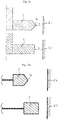
Spannungsüberschläge (Lichtbögen) treten bevorzugterweise aus bestehenden Spitzen und scharfen Kanten eines elektrisch leitfähigen Materials aus, weil an derartig geformten Oberflächen eine Feldstärkeüberhöhung vorliegt. Um nun eine Verschleißreduzierung an den Zündelektroden vorzusehen, ist eine möglichst niedrige Zündspannung beziehungsweise Überschlagsspannung von Vorteil. Läuft die Zündelektrode an ihrem Außenumfang spitz zu, besitzt also eine Keilform entlang des gesamten Umfangs der Zündelektrode, kann insgesamt mit einer geringeren Überschlagsspannung bzw. Zündspannung gearbeitet werden, die einen geringeren Verschleißgrad hervorruft.Voltage flashovers (arcs) preferably emerge from existing tips and sharp edges of an electrically conductive material because there is an increase in field strength on such shaped surfaces. In order to reduce wear on the ignition electrodes, the lowest possible ignition voltage or breakdown voltage is advantageous. If the ignition electrode tapers on its outer circumference, ie has a wedge shape along the entire circumference of the ignition electrode, it is possible overall to work with a lower breakdown voltage or ignition voltage, which causes a lower degree of wear.
Alternativ dazu, kann man bei gleicher Zündspannung einen wesentlich längeren Zündfunken erzeugen und damit die Zündfläche zum Entzünden des Gemisches erhöhen. Indem nun eine spitz zulaufende scheiben- oder rahmenförmige Zündelektrode weiter entfernt zu einer zugehörigen Massenelektrode angeordnet werden kann, ergibt sich ein wesentlich größerer Strömungsquerschnitt beim Umströmen der Zündelektrode in einem darüber liegenden Bereich, sodass ein Ausströmen eines verbrannten Gases durch Einströmen eines neuen zündfähigen Gemisches sehr viel leichter bewerkstelligt werden kann. Unterstützend wirkt dabei weiter die durch die Spitze beziehungsweise Kante hervorgerufene Verwirbelung beim Entlangströmen des zündfähigen Gemisches.Alternatively, one can generate a considerably longer ignition spark with the same ignition voltage and thus increase the ignition area for igniting the mixture. Since a tapered disc-shaped or frame-shaped ignition electrode can now be arranged further away from an associated ground electrode, there is a much larger flow cross-section when flowing around the ignition electrode in an area above it, so that a Escaping a burned gas by inflowing a new ignitable mixture can be done much easier. The turbulence caused by the tip or edge also acts as a support when the ignitable mixture flows along.
Vorzugsweise weist die Vorkammer eine zylindrisch geformte Ausnehmung auf, in der die scheiben- oder rahmenförmige Zündelektrode angeordnet ist, wobei die zylindrische Ausnehmung und die scheiben- oder rahmenförmige Zündelektrode koaxial zueinander ausgerichtet sind, sodass der minimale Abstand vom Außenumfang der Zündelektrode hin zur Innenwand der Vorkammer entlang des Außenumfangs der - oder rahmenförmigen Zündelektrode gleich ist.The prechamber preferably has a cylindrically shaped recess in which the disk-shaped or frame-shaped ignition electrode is arranged, the cylindrical recess and the disk-shaped or frame-shaped ignition electrode being aligned coaxially with one another, so that the minimum distance from the outer circumference of the ignition electrode to the inner wall of the prechamber along the outer circumference of the - or frame-shaped ignition electrode is the same.
Weiter kann nach der Erfindung vorgesehen sein, dass mehrere Überströmungskanäle vorhanden sind, die eine Verbindung der Vorkammer nach Außen erzeugen. Selbstverständlich ist dabei auch der Fall umfasst, dass nur ein Überströmungskanal vorhanden ist, der eine Verbindung der Vorkammer nach Außen erzeugt. Bei mehreren Überströmungskanälen ist es dabei von Vorteil, wenn diese in einer tangentialen oder schrägtangentialen Anordnung zur Längsachse, vorzugsweise der Symmetrieachse der Vorkammer angeordnet sind, sodass beim Ausströmen eines entflammten Gemisches aus der Vorkammer ein Sog erzeugt wird. Die Eintrittspunkte der Überströmungskanäle in die Vorkammer sind dabei also nicht radial zur Symmetrieachse oder zur Längsachse der Vorkammer ausgerichtet, sondern gehen von einem Kreis, der die Längsachse beziehungsweise die Symmetrieachse der Vorkammer als Mittelpunkt aufweist und der vorzugsweise senkrecht dazu steht, tangential oder schrägtangential ab. Eine schrägtangentiale Anordnung eines Überströmungskanals bedeutet, dass dessen Symmetrielinie mit einer Tangente an einen Kreis mit Mittelpunkt in der Symmetrieachse der Vorkammer eine tangential zu dem genannten Kreis orientierte Ebene aufspannt.It can further be provided according to the invention that a plurality of overflow channels are present, which produce a connection of the prechamber to the outside. Of course, this also includes the case that only one overflow channel is present, which creates a connection of the prechamber to the outside. In the case of a plurality of overflow channels, it is advantageous if these are arranged in a tangential or obliquely tangential arrangement with respect to the longitudinal axis, preferably the axis of symmetry of the prechamber, so that a suction is generated when an inflamed mixture flows out of the prechamber. The entry points of the overflow channels into the prechamber are therefore not aligned radially to the axis of symmetry or to the longitudinal axis of the prechamber, but proceed from a circle which has the longitudinal axis or the axis of symmetry of the prechamber as the center and which is preferably perpendicular thereto, tangentially or obliquely tangentially. An obliquely tangential arrangement of an overflow channel means that its line of symmetry spans a plane oriented tangentially to the said circle with a tangent to a circle with a center in the axis of symmetry of the prechamber.
Vorteilhaft ist dies, da bei der scheiben- oder rahmenförmigen Zündelektrode auch der Zündfunke, also plasmaförmiges Brenngas-Luft-Gemisch, dem Sog, der durch die tangentiale Anordnung der Überströmungskanäle gebildet wird, ausgesetzt wird. Das ruft ein tendenzielles Wandern des Zündfunkens entlang der Sogrichtung hervor, sodass sich der Zündfunken während seines Bestehens in Richtung der Sogwirkung bewegt. Dies trägt zu einer Abschwächung des lokalen Verschleißes an den Elektrodenoberflächen (Zündelektrode und Massenelektrode) bei, und bewirkt durch die Bewegung des Zündfunkens zudem, dass ein größerer Bereich des entzündbaren Gemisches mit dem Zündfunken in Berührung kommt.This is advantageous because, in the case of the disk-shaped or frame-shaped ignition electrode, the ignition spark, that is to say the plasma-shaped mixture of fuel gas and air, the suction that passes through the tangential arrangement of the overflow channels is formed, is suspended. This triggers a tendency for the ignition spark to move along the suction direction, so that the ignition spark moves in the direction of the suction effect during its existence. This contributes to a weakening of the local wear on the electrode surfaces (ignition electrode and ground electrode) and also causes a larger area of the flammable mixture to come into contact with the ignition spark due to the movement of the ignition spark.
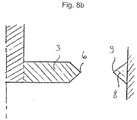
Nach einer weiteren Modifikation der vorliegenden Erfindung ist an der Innenwand der Vorkammer, die die Massenelektrode darstellt, eine Erhebung vorgesehen, vorzugsweise eine eine Spitze bildende Erhebung, die in ihrer Innenumfangsrichtung umlaufend ausgebildet ist und vorzugsweise auf gleicher Höhe wie die scheiben- oder rahmenförmige Zündelektrode angeordnet ist.According to a further modification of the present invention, an elevation is provided on the inner wall of the prechamber, which represents the ground electrode, preferably an elevation forming a tip, which is circumferential in its inner circumferential direction and is preferably arranged at the same height as the disk-shaped or frame-shaped ignition electrode is.
Demzufolge kann auch an der Innenwand der Vorkammer, also an der Massenelektrode eine Erhebung beziehungsweise scharfkantige Erhebung oder auch Spitze vorhanden sein, um eine Überschlagsspannung abzusenken und die damit einhergehenden Verschleißzustände abzumildern.Accordingly, an elevation or sharp-edged elevation or tip can also be present on the inner wall of the prechamber, that is to say on the ground electrode, in order to lower a breakdown voltage and to mitigate the associated wear conditions.
Weiter kann vorteilhafterweise vorgesehen sein, dass die Vorkammerzündvorrichtung eine Vorkammerkerze ist, die an einer Brennkraftmaschine lösbar befestigbar ist. Typischerweise verfügt eine solche Vorkammerkerze über ein Außengewinde, mit dem es lösbar an einem Motor befestigbar ist, sodass die Spitze der Vorkammerkerze, die Vorkammerkappe in einen Hauptbrennraum eines Zylinders hineinragt. Die Spitze weist dabei die Überströmungskanäle auf, sodass der Hauptbrennraum einer Brennkraftmaschine mit der in der Kerze angeordneten Vorkammer zusammenwirken kann.Furthermore, it can advantageously be provided that the prechamber ignition device is a prechamber candle that can be detachably attached to an internal combustion engine. Such a prechamber candle typically has an external thread with which it can be detachably attached to an engine, so that the tip of the prechamber candle, the prechamber cap, projects into a main combustion chamber of a cylinder. The tip has the overflow channels so that the main combustion chamber of an internal combustion engine can interact with the prechamber arranged in the candle.
Die Erfindung umfasst zudem eine Brennkraftmaschine mit einer Vorkammerzündvorrichtung nach einer der vorstehend beschriebenen Varianten.The invention also includes an internal combustion engine with a prechamber ignition device according to one of the variants described above.
Weitere Merkmale, Einzelheiten und Vorteile der vorliegenden Erfindung werden anhand der nachfolgenden Figurenbeschreibung ersichtlich. Es zeigen:
- Fig. 1:
- eine Schnittansicht einer Vorkammerzündvorrichtung nach der Erfindung,
- Fig. 1A:
- ein Diagramm zum Darstellen des Druckverlaufbereichs in einem Brennraum,
- Fig. 2a-b:
- schematische Darstellungen der erfindungsgemäßen Elektrode,
- Fig. 3 a-c:
- verschiedene Darstellungen eines Teilabschnitts unterschiedlicher erfindungsgemäßer Zündvorrichtungen,
- Fig. 4:
- eine Schnittansicht im Querschnitt zur Darstellung einer tangentialen Anordnung von Überströmungskanälen,
- Fig. 5:
- mehrere Schaubilder zur Darstellung einer sich aufgrund eines Sogs bewegenden Funkenstrecke,
- Fig. 6a:
- eine erfindungsgemäße Zündelektrode mit spitz zulaufender Kante im Umfangsbereich in Gegenüberstellung zu einer herkömmlichen flachen Kante,
- Fig. 6b:
- eine erfindungsgemäße Zündelektrode mit spitz zulaufender Kante im Umfangsbereich in Gegenüberstellung zu einer herkömmlichen flachen Kante mit Beschichtung,
- Fig. 6c:
- eine erfindungsgemäße Zündelektrode mit spitz zulaufender Kante im Umfangsbereich in Gegenüberstellung zu einer herkömmlichen flachen Kante mit Beschichtung nach einer weiteren Ausführungsform,
- Fig. 7a:
- eine erfindungsgemäße spitz zulaufende Kante einer Zündelektrode mit vergrößertem Abstand zu einer zugehörigen Massenelektrode in Gegenüberstellung mit einer herkömmlichen flachen und in ihrem Abstand nicht vergrößerten Zündelektrode,
- Fig. 7b:
- eine erfindungsgemäße spitz zulaufende Kante einer Zündelektrode mit vergrößertem Abstand zu einer zugehörigen Massenelektrode in Gegenüberstellung mit einer herkömmlichen flachen und in ihrem Abstand nicht vergrößerten Zündelektrode einer weitere Ausführungsform,
- Fig. 8a:
- eine Darstellung mit einer erfindungsgemäßen Zündelektrode, die in ihrem Umfangsbereich spitz zuläuft und mit ihrer Spitze auf eine Spitze an der Innenwand der Vorkammer gerichtet ist und eine Beschichtung aufweist, und
- Fig. 8b:
- eine Darstellung mit einer erfindungsgemäßen beschichtungsfreien Zündelektrode, die in ihrem Umfangsbereich spitz zuläuft und mit ihrer Spitze auf eine Spitze an der Innenwand der Vorkammer gerichtet ist.
- Fig. 1:
- 2 shows a sectional view of a prechamber ignition device according to the invention,
- Fig. 1A:
- 1 shows a diagram for illustrating the pressure curve area in a combustion chamber,
- 2a-b:
- schematic representations of the electrode according to the invention,
- 3 ac:
- different representations of a partial section of different ignition devices according to the invention,
- Fig. 4:
- 2 shows a sectional view in cross section to illustrate a tangential arrangement of overflow channels,
- Fig. 5:
- several diagrams to illustrate a spark gap moving due to suction,
- Fig. 6a:
- an ignition electrode according to the invention with a tapered edge in the circumferential area in comparison to a conventional flat edge,
- Fig. 6b:
- an ignition electrode according to the invention with a tapered edge in the peripheral region in comparison to a conventional flat edge with a coating,
- Fig. 6c:
- an ignition electrode according to the invention with a tapered edge in the peripheral area in comparison to a conventional flat edge with a coating according to a further embodiment,
- Fig. 7a:
- a tapered edge of an ignition electrode according to the invention with an increased distance from an associated ground electrode in comparison with a conventional flat and not enlarged in distance,
- Fig. 7b:
- an inventive tapered edge of an ignition electrode with an increased distance from an associated ground electrode in comparison with a conventional flat and not enlarged in distance, another embodiment,
- 8a:
- a representation with an ignition electrode according to the invention, which tapers in its peripheral region and is pointed with its tip at a tip on the inner wall of the prechamber and has a coating, and
- 8b:
- a representation with a coating-free ignition electrode according to the invention, which tapers in its peripheral region and is pointed with its tip at a tip on the inner wall of the prechamber.
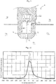
Typischerweise wird die Vorkammerzündvorrichtung 1 durch einen Zylinderblock 10 in einen Hauptbrennraum 11 eines Zylinders teilweise eingeführt, sodass die Spitze der Vorkammerzündvorrichtung 1, die sogenannte Vorkammerkappe mit ihren Überströmungskanälen 7 in einen Hauptbrennraum 11 eines Zylinders hineinragt. Durch eine Zuführung eines Kraftstoff-Luft-Gemisches in den Hauptbrennraum gelangt auch eine entsprechende Menge davon in die Vorkammer 2, da der Kompressionstakt des Zylinders den eingesprühten Kraftstoff über die Überströmungskanäle 7 in die Vorkammer 2 einführt. Zu einem gewünschten Zeitpunkt wird dann ein Zündfunken zwischen der Zündelektrode 3 und der Massenelektrode 21 erzeugt, die ein Entflammen des in der Vorkammer 2 befindlichen Gemisches bewirkt. Durch die Entflammung expandiert das Gemisch stark und schießt aus den Übertrömungskanälen 7 in den Hauptbrennraum, wo es aufgrund des Herausströmens des entflammten Gemisches aus den Überströmungskanälen 7 zu einem vergleichsweise gut reproduzierbaren und wohl koordinierten Entzünden des in der Hauptbrennkammer 11 befindlichen Gemisches kommt.Typically, the prechamber ignition device 1 is partially inserted through a
Weiter erkennt man Ausnehmungen 5, die in der Zündelektrode 3 angeordnet sind. Durch diese Ausnehmungen 5 kann ein zu entzündendes Gasgemisch oder auch ein bereits entzündetes Gasgemisch hindurchtreten, sodass bei einem Einführen eines zu entzündenden Gasgemisches ein besonders wirkungsvolles Spülen erreicht wird. Vorliegend erkennt man zudem, dass die insgesamt vier dargestellten Ausnehmungen 5 äquidistant zueinander angeordnet sind, jeweils also den gleichen Abstand in der kreisförmigen Zündelektrodenscheibe aufweisen.
Indem der Sog nicht nur auf das Gemisch, sondern auch auf den Zündfunken 4 wirkt, wird der Bereich, in dem das Gemisch mit einem Funken in Berührung kommt, vergrößert. Dies führt zu einer gleichmäßigeren Entflammung des in der Vorkammer 2 enthaltenen Gemisches, sodass man dem Idealzustand eines gleichzeitigen Entflammens des in der Vorkammer befindlichen Gemisches näher kommt.The fact that the suction acts not only on the mixture but also on the ignition spark 4 increases the area in which the mixture comes into contact with a spark. This leads to a more uniform ignition of the mixture contained in the
In der
Der Effekt, wonach ein Lichtbogen bevorzugt aus einer Spitze oder einer scharfkantigen Erhebung austritt, kann darüber hinaus zu der in
Claims (17)
die Vorkammer (2) eine zylindrische Ausnehmung (22) aufweist, in der die scheibenförmige Zündelektrode (3) angeordnet ist, und
die zylindrische Ausnehmung (22) und die scheibenförmige Zündelektrode (3) koaxial zueinander ausgerichtet sind, so dass der minimale Abstand vom Außenumfang der Zündelektrode (3) hin zur Innenwand (21) der Vorkammer (2) entlang des Außenumfangs der scheibenförmigen Zündelektrode (3) gleich ist.Pre-chamber ignition device (1) according to one of the preceding claims, wherein
the prechamber (2) has a cylindrical recess (22) in which the disk-shaped ignition electrode (3) is arranged, and
the cylindrical recess (22) and the disk-shaped ignition electrode (3) are aligned coaxially with one another, so that the minimum distance from the outer circumference of the ignition electrode (3) to the inner wall (21) of the prechamber (2) along the outer circumference of the disk-shaped ignition electrode (3) is equal to.
mehrere Überströmungskanäle (7), die eine Verbindung der Vorkammer (2) nach außen erzeugen, vorhanden sind, und
die mehreren Überströmungskanäle (7) in einer tangentialen oder schrägtangentialen Anordnung zur Längsachse, vorzugsweise der Symmetrieachse der Vorkammer (2) angeordnet sind, so dass beim Ausströmen eines entflammten Gemisches aus der Vorkammer (2) ein Sog erzeugt wird.Pre-chamber ignition device (1) according to one of the preceding claims, wherein
a plurality of overflow channels (7), which produce a connection of the prechamber (2) to the outside, are present, and
the plurality of overflow channels (7) in a tangential or oblique-tangential arrangement to the longitudinal axis, preferably the axis of symmetry the antechamber (2) are arranged so that a suction is generated when an inflamed mixture flows out of the antechamber (2).
Applications Claiming Priority (1)
| Application Number | Priority Date | Filing Date | Title |
|---|---|---|---|
| CH00783/18A CH715114A1 (en) | 2018-06-19 | 2018-06-19 | Pre-chamber ignition device for igniting a fuel-air mixture. |
Publications (1)
| Publication Number | Publication Date |
|---|---|
| EP3584895A1 true EP3584895A1 (en) | 2019-12-25 |
Family
ID=66630195
Family Applications (1)
| Application Number | Title | Priority Date | Filing Date |
|---|---|---|---|
| EP19175852.3A Withdrawn EP3584895A1 (en) | 2018-06-19 | 2019-05-22 | Prechamber ignition device for igniting a fuel-air mixture |
Country Status (2)
| Country | Link |
|---|---|
| EP (1) | EP3584895A1 (en) |
| CH (1) | CH715114A1 (en) |
Citations (3)
| Publication number | Priority date | Publication date | Assignee | Title |
|---|---|---|---|---|
| US1334135A (en) * | 1919-02-06 | 1920-03-16 | Ursin L Cuevas | Spark-plug |
| US5554908A (en) | 1994-03-29 | 1996-09-10 | Kuhnert; Dieter | Precombustion chamber device |
| DE102008042625A1 (en) * | 2008-10-06 | 2010-04-08 | Robert Bosch Gmbh | Spark plug, in particular for a stationary internal combustion engine |
Family Cites Families (4)
| Publication number | Priority date | Publication date | Assignee | Title |
|---|---|---|---|---|
| US20050211217A1 (en) * | 2004-03-23 | 2005-09-29 | Boley William C | Pre-chambered type spark plug with pre-chamber entirely below a bottom surface of a cylinder head |
| JP2006228522A (en) * | 2005-02-16 | 2006-08-31 | Denso Corp | Spark plug for internal combustion engine |
| US7521849B2 (en) * | 2005-09-29 | 2009-04-21 | Federal-Mogul World Wide, Inc. | Spark plug with welded sleeve on electrode |
| JP5065168B2 (en) * | 2008-06-13 | 2012-10-31 | 大阪瓦斯株式会社 | engine |
-
2018
- 2018-06-19 CH CH00783/18A patent/CH715114A1/en not_active Application Discontinuation
-
2019
- 2019-05-22 EP EP19175852.3A patent/EP3584895A1/en not_active Withdrawn
Patent Citations (3)
| Publication number | Priority date | Publication date | Assignee | Title |
|---|---|---|---|---|
| US1334135A (en) * | 1919-02-06 | 1920-03-16 | Ursin L Cuevas | Spark-plug |
| US5554908A (en) | 1994-03-29 | 1996-09-10 | Kuhnert; Dieter | Precombustion chamber device |
| DE102008042625A1 (en) * | 2008-10-06 | 2010-04-08 | Robert Bosch Gmbh | Spark plug, in particular for a stationary internal combustion engine |
Also Published As
| Publication number | Publication date |
|---|---|
| CH715114A1 (en) | 2019-12-30 |
Similar Documents
| Publication | Publication Date | Title |
|---|---|---|
| EP0675272B1 (en) | Prechamber ignition device | |
| DE102018130539B4 (en) | Pre-chamber spark plug assembly | |
| DE112015000466B4 (en) | IGNITER AND METHOD FOR GENERATION OF PLASMA DISCHARGE RADIATION | |
| EP3591775B1 (en) | Pre-chamber cap with conical fluid openings for a pre-chamber igniter plug and a pre-chamber igniter plug and a method for producing the pre-chamber cap | |
| DE19849317A1 (en) | Spark plug for internal combustion engine | |
| DE2647881A1 (en) | PROCEDURE FOR IGNITING A FUEL-AIR MIXTURE AND ARRANGEMENT FOR CARRYING OUT THE PROCEDURE | |
| DE102010004851A1 (en) | Spark plug for a gas-powered internal combustion engine | |
| DE102014004943A1 (en) | prechamber | |
| DE102012022872A1 (en) | Ignition device for combustion engine i.e. gas engine, has cylindrical central bore fluidly connected between ignition chamber and combustion chamber, where diameter of central bore is greater than diameter of another cylindrical bore | |
| DE112020002454T5 (en) | internal combustion engine and spark plug | |
| DE102009055038A1 (en) | laser ignition device | |
| DE102020100827B4 (en) | Pre-chamber system, internal combustion engine with pre-chamber system and method for igniting a fuel-air mixture | |
| DE60015200T2 (en) | Directed plasma jet spark plug | |
| DE112016006462T5 (en) | INTERNAL COMBUSTION ENGINE AND METHOD FOR IGNITING A FUEL | |
| DE102014015707A1 (en) | prechamber | |
| EP3899228A1 (en) | Cylinder head for an internal combustion engine | |
| DE19636712A1 (en) | Spark ignition system of an internal combustion engine | |
| WO1985003109A1 (en) | Internal combustion engine with ignition by high energy rays which may be introduced into the combustion chamber | |
| EP4158742A1 (en) | Prechamber spark plug having profiled ground electrode | |
| DE102012213939B4 (en) | spark plug | |
| DE102012223640B4 (en) | Ignition device for an internal combustion engine and internal combustion engine | |
| EP3584895A1 (en) | Prechamber ignition device for igniting a fuel-air mixture | |
| DE102009046092B4 (en) | Spark plug with at least three height-offset ground electrodes | |
| EP1265328B1 (en) | Spark plug of an internal combustion engine | |
| DE19747701C2 (en) | Plasma jet ignition for internal combustion engines |
Legal Events
| Date | Code | Title | Description |
|---|---|---|---|
| PUAI | Public reference made under article 153(3) epc to a published international application that has entered the european phase |
Free format text: ORIGINAL CODE: 0009012 |
|
| AK | Designated contracting states |
Kind code of ref document: A1 Designated state(s): AL AT BE BG CH CY CZ DE DK EE ES FI FR GB GR HR HU IE IS IT LI LT LU LV MC MK MT NL NO PL PT RO RS SE SI SK SM TR |
|
| AX | Request for extension of the european patent |
Extension state: BA ME |
|
| STAA | Information on the status of an ep patent application or granted ep patent |
Free format text: STATUS: THE APPLICATION IS DEEMED TO BE WITHDRAWN |
|
| 18D | Application deemed to be withdrawn |
Effective date: 20200626 |