EP3584856A1 - Battery module and battery pack comprising same - Google Patents
Battery module and battery pack comprising same Download PDFInfo
- Publication number
- EP3584856A1 EP3584856A1 EP18863470.3A EP18863470A EP3584856A1 EP 3584856 A1 EP3584856 A1 EP 3584856A1 EP 18863470 A EP18863470 A EP 18863470A EP 3584856 A1 EP3584856 A1 EP 3584856A1
- Authority
- EP
- European Patent Office
- Prior art keywords
- electrode leads
- battery module
- battery
- base member
- coupled
- Prior art date
- Legal status (The legal status is an assumption and is not a legal conclusion. Google has not performed a legal analysis and makes no representation as to the accuracy of the status listed.)
- Granted
Links
Images


Classifications
-
- H—ELECTRICITY
- H01—ELECTRIC ELEMENTS
- H01M—PROCESSES OR MEANS, e.g. BATTERIES, FOR THE DIRECT CONVERSION OF CHEMICAL ENERGY INTO ELECTRICAL ENERGY
- H01M50/00—Constructional details or processes of manufacture of the non-active parts of electrochemical cells other than fuel cells, e.g. hybrid cells
- H01M50/50—Current conducting connections for cells or batteries
- H01M50/531—Electrode connections inside a battery casing
- H01M50/536—Electrode connections inside a battery casing characterised by the method of fixing the leads to the electrodes, e.g. by welding
-
- H—ELECTRICITY
- H01—ELECTRIC ELEMENTS
- H01M—PROCESSES OR MEANS, e.g. BATTERIES, FOR THE DIRECT CONVERSION OF CHEMICAL ENERGY INTO ELECTRICAL ENERGY
- H01M50/00—Constructional details or processes of manufacture of the non-active parts of electrochemical cells other than fuel cells, e.g. hybrid cells
- H01M50/50—Current conducting connections for cells or batteries
- H01M50/502—Interconnectors for connecting terminals of adjacent batteries; Interconnectors for connecting cells outside a battery casing
-
- H—ELECTRICITY
- H01—ELECTRIC ELEMENTS
- H01M—PROCESSES OR MEANS, e.g. BATTERIES, FOR THE DIRECT CONVERSION OF CHEMICAL ENERGY INTO ELECTRICAL ENERGY
- H01M50/00—Constructional details or processes of manufacture of the non-active parts of electrochemical cells other than fuel cells, e.g. hybrid cells
- H01M50/20—Mountings; Secondary casings or frames; Racks, modules or packs; Suspension devices; Shock absorbers; Transport or carrying devices; Holders
- H01M50/204—Racks, modules or packs for multiple batteries or multiple cells
-
- H—ELECTRICITY
- H01—ELECTRIC ELEMENTS
- H01M—PROCESSES OR MEANS, e.g. BATTERIES, FOR THE DIRECT CONVERSION OF CHEMICAL ENERGY INTO ELECTRICAL ENERGY
- H01M50/00—Constructional details or processes of manufacture of the non-active parts of electrochemical cells other than fuel cells, e.g. hybrid cells
- H01M50/20—Mountings; Secondary casings or frames; Racks, modules or packs; Suspension devices; Shock absorbers; Transport or carrying devices; Holders
- H01M50/249—Mountings; Secondary casings or frames; Racks, modules or packs; Suspension devices; Shock absorbers; Transport or carrying devices; Holders specially adapted for aircraft or vehicles, e.g. cars or trains
-
- H—ELECTRICITY
- H01—ELECTRIC ELEMENTS
- H01M—PROCESSES OR MEANS, e.g. BATTERIES, FOR THE DIRECT CONVERSION OF CHEMICAL ENERGY INTO ELECTRICAL ENERGY
- H01M50/00—Constructional details or processes of manufacture of the non-active parts of electrochemical cells other than fuel cells, e.g. hybrid cells
- H01M50/50—Current conducting connections for cells or batteries
- H01M50/502—Interconnectors for connecting terminals of adjacent batteries; Interconnectors for connecting cells outside a battery casing
- H01M50/503—Interconnectors for connecting terminals of adjacent batteries; Interconnectors for connecting cells outside a battery casing characterised by the shape of the interconnectors
-
- H—ELECTRICITY
- H01—ELECTRIC ELEMENTS
- H01M—PROCESSES OR MEANS, e.g. BATTERIES, FOR THE DIRECT CONVERSION OF CHEMICAL ENERGY INTO ELECTRICAL ENERGY
- H01M50/00—Constructional details or processes of manufacture of the non-active parts of electrochemical cells other than fuel cells, e.g. hybrid cells
- H01M50/50—Current conducting connections for cells or batteries
- H01M50/502—Interconnectors for connecting terminals of adjacent batteries; Interconnectors for connecting cells outside a battery casing
- H01M50/505—Interconnectors for connecting terminals of adjacent batteries; Interconnectors for connecting cells outside a battery casing comprising a single busbar
-
- H—ELECTRICITY
- H01—ELECTRIC ELEMENTS
- H01M—PROCESSES OR MEANS, e.g. BATTERIES, FOR THE DIRECT CONVERSION OF CHEMICAL ENERGY INTO ELECTRICAL ENERGY
- H01M50/00—Constructional details or processes of manufacture of the non-active parts of electrochemical cells other than fuel cells, e.g. hybrid cells
- H01M50/50—Current conducting connections for cells or batteries
- H01M50/502—Interconnectors for connecting terminals of adjacent batteries; Interconnectors for connecting cells outside a battery casing
- H01M50/514—Methods for interconnecting adjacent batteries or cells
- H01M50/516—Methods for interconnecting adjacent batteries or cells by welding, soldering or brazing
-
- H—ELECTRICITY
- H01—ELECTRIC ELEMENTS
- H01M—PROCESSES OR MEANS, e.g. BATTERIES, FOR THE DIRECT CONVERSION OF CHEMICAL ENERGY INTO ELECTRICAL ENERGY
- H01M50/00—Constructional details or processes of manufacture of the non-active parts of electrochemical cells other than fuel cells, e.g. hybrid cells
- H01M50/50—Current conducting connections for cells or batteries
- H01M50/531—Electrode connections inside a battery casing
-
- B—PERFORMING OPERATIONS; TRANSPORTING
- B23—MACHINE TOOLS; METAL-WORKING NOT OTHERWISE PROVIDED FOR
- B23K—SOLDERING OR UNSOLDERING; WELDING; CLADDING OR PLATING BY SOLDERING OR WELDING; CUTTING BY APPLYING HEAT LOCALLY, e.g. FLAME CUTTING; WORKING BY LASER BEAM
- B23K20/00—Non-electric welding by applying impact or other pressure, with or without the application of heat, e.g. cladding or plating
- B23K20/10—Non-electric welding by applying impact or other pressure, with or without the application of heat, e.g. cladding or plating making use of vibrations, e.g. ultrasonic welding
-
- B—PERFORMING OPERATIONS; TRANSPORTING
- B23—MACHINE TOOLS; METAL-WORKING NOT OTHERWISE PROVIDED FOR
- B23K—SOLDERING OR UNSOLDERING; WELDING; CLADDING OR PLATING BY SOLDERING OR WELDING; CUTTING BY APPLYING HEAT LOCALLY, e.g. FLAME CUTTING; WORKING BY LASER BEAM
- B23K2101/00—Articles made by soldering, welding or cutting
- B23K2101/36—Electric or electronic devices
- B23K2101/38—Conductors
-
- H—ELECTRICITY
- H01—ELECTRIC ELEMENTS
- H01M—PROCESSES OR MEANS, e.g. BATTERIES, FOR THE DIRECT CONVERSION OF CHEMICAL ENERGY INTO ELECTRICAL ENERGY
- H01M2220/00—Batteries for particular applications
- H01M2220/20—Batteries in motive systems, e.g. vehicle, ship, plane
-
- H—ELECTRICITY
- H01—ELECTRIC ELEMENTS
- H01M—PROCESSES OR MEANS, e.g. BATTERIES, FOR THE DIRECT CONVERSION OF CHEMICAL ENERGY INTO ELECTRICAL ENERGY
- H01M50/00—Constructional details or processes of manufacture of the non-active parts of electrochemical cells other than fuel cells, e.g. hybrid cells
- H01M50/20—Mountings; Secondary casings or frames; Racks, modules or packs; Suspension devices; Shock absorbers; Transport or carrying devices; Holders
- H01M50/204—Racks, modules or packs for multiple batteries or multiple cells
- H01M50/207—Racks, modules or packs for multiple batteries or multiple cells characterised by their shape
- H01M50/211—Racks, modules or packs for multiple batteries or multiple cells characterised by their shape adapted for pouch cells
-
- Y—GENERAL TAGGING OF NEW TECHNOLOGICAL DEVELOPMENTS; GENERAL TAGGING OF CROSS-SECTIONAL TECHNOLOGIES SPANNING OVER SEVERAL SECTIONS OF THE IPC; TECHNICAL SUBJECTS COVERED BY FORMER USPC CROSS-REFERENCE ART COLLECTIONS [XRACs] AND DIGESTS
- Y02—TECHNOLOGIES OR APPLICATIONS FOR MITIGATION OR ADAPTATION AGAINST CLIMATE CHANGE
- Y02E—REDUCTION OF GREENHOUSE GAS [GHG] EMISSIONS, RELATED TO ENERGY GENERATION, TRANSMISSION OR DISTRIBUTION
- Y02E60/00—Enabling technologies; Technologies with a potential or indirect contribution to GHG emissions mitigation
- Y02E60/10—Energy storage using batteries
Definitions
- the present disclosure relates to a battery module and a battery pack including the battery module, and more particularly, to a battery module and a battery pack including the battery module, which allows electrode leads to be coupled to a bus bar without being bent.
- a nickel-cadmium battery or a hydrogen ion battery has been used as the secondary battery.
- a lithium secondary battery is recently widely used because charging and discharging is free due to rare memory effect in comparison with a nickel-based secondary battery, a self-discharge rate is very low, and an energy density is high.
- the lithium secondary battery mainly uses a lithium oxide and a carbonaceous material as a positive electrode active material and a negative electrode active material, respectively.
- the lithium secondary battery includes an electrode assembly in which a positive electrode plate and a negative electrode plate, respectively coated with the positive electrode active material and the negative electrode active material, are arranged with a separator therebetween, and an outer member, that is a battery case, which seals and receives the electrode assembly together with an electrolyte solution.
- the lithium secondary battery includes a positive electrode, a negative electrode, and a separator interposed therebetween and an electrolyte.
- the lithium secondary battery is classified into a lithium ion battery (LIB) and a polymer lithium ion battery (PLIB).
- LIB lithium ion battery
- PKIB polymer lithium ion battery
- an electrode of the lithium secondary battery is prepared by applying the positive or negative electrode active material to a current collector made of aluminum or copper sheet, mesh, film, foil, or the like and then drying the same.
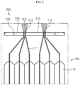
- FIG. 1 is a diagram showing that an electrode lead and a bus bar provided at a conventional battery cell are electrically coupled.
- electrode leads 20 respectively provided at a plurality of battery cells 10 are bent to contact a surface of a bus bar 30 and then are coupled thereto by welding 40.
- numerous manual works are needed to maintain the bending shape of the electrode leads 20.
- the electrode leads 20 and the bus bar 30 are not closely attached due to the elastic restoration force of the electrode leads 20 made of metal.
- the plurality of electrode leads 20 are overlapped at one point of the bus bar 30 and then coupled by the welding 40, heat is concentrated on the uppermost electrode lead 20, thereby deteriorating the welding performance.
- the present disclosure is designed to providing a battery module and a battery pack including the battery module, which may improve the welding performance since the heat generated during welding is uniformly distributed to all electrode leads.
- the present disclosure is designed to providing a battery module and a battery pack including the battery module, which may improve the automation ratio of a production line since manual works for bending the electrode leads are eliminated.
- a battery module comprising: a battery cell stack in which a plurality of battery cells are stacked; and a bus bar to which electrode leads respectively provided at the plurality of battery cells are coupled, wherein the bus bar presses the electrode leads so that the bus bar and the electrode leads are electrically connected.
- the bus bar may include: a base member electrically connected to the electrode leads; and a rotating member rotatably coupled to the base member to press the electrode leads interposed between the rotating member and the base member.
- the rotating member may be provided in a pair, and the pair of rotating members may be respectively coupled to both side ends of the base member.
- the base member may include: a pair of horizontal members formed in a horizontal direction; and a vertical member formed in a vertical direction to connect the pair of horizontal members.
- a length of the horizontal member in the horizontal direction may be longer than a length of the vertical member in the horizontal direction to form a space between ends of the pair of horizontal members, and the pair of rotating members may be rotatably disposed in the space.
- an electrode lead group in which the plurality of electrode leads are coupled to each other may be interposed between the base member and the rotating member.
- the plurality of electrode leads may be coupled by ultrasonic welding to form the electrode lead group.
- the base member and the rotating member between which the electrode leads are interposed may be coupled by welding.
- a battery pack including the battery module described above, and there is also provided a vehicle including the battery module.
- the electrode leads are coupled to the bus bar without being bent, thereby allowing the electrode leads to be closely attached to the bus bar.
- the heat generated during welding is uniformly distributed to all electrode leads, thereby improving the welding performance.
- 'combine' or 'connect' may refer not only to a case where one member and another member are directly combined or directly connected but also a case where one member is indirectly combined with another member via a connecting member or is indirectly connected.
- FIG. 2 is a schematic perspective view showing that electrode leads and a bus bar are separated in a state where a rotating member is rotated not to press the electrode leads, in a battery module according to an embodiment of the present disclosure
- FIG. 3 is a side sectional view showing that the electrode leads and the bus bar are coupled in a state where the rotating member is rotated not to press the electrode leads, in the battery module according to an embodiment of the present disclosure
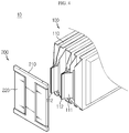
- FIG. 4 is a schematic perspective view showing that the electrode leads and the bus bar are separated in a state where the rotating member is rotated to press the electrode leads, in the battery module according to an embodiment of the present disclosure
- FIG. 3 is a side sectional view showing that the electrode leads and the bus bar are coupled in a state where the rotating member is rotated not to press the electrode leads, in the battery module according to an embodiment of the present disclosure
- FIG. 4 is a schematic perspective view showing that the electrode leads and the bus bar are separated in a state where the rotating member is rotated to press the electrode leads, in the battery module according to
- FIG. 5 is a side sectional view showing that the electrode leads and the bus bar are coupled in a state where the rotating member is rotated to press the electrode leads, in the battery module according to an embodiment of the present disclosure
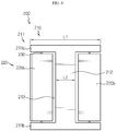
- FIG. 6 is a plane view showing the bus bar of the battery module according to an embodiment of the present disclosure.
- a battery module 10 includes a battery cell stack 100 and a bus bar 200.
- the battery cell stack 100 may include a plurality of battery cells 110 stacked on one another (see FIGS. 2 to 5 ).
- the battery cell 110 may have various structures, and the plurality of battery cells 110 may be stacked in various ways.
- the battery cell 110 may be configured such that a plurality of unit cells arranged in the order of a positive electrode plate, a separator and a negative electrode plate or bi-cells arranged in the order of a positive electrode plate, a separator, a negative electrode plate, a separator, a positive electrode plate, a separator and a negative electrode plate are stacked appropriate for the battery capacity.
- the battery cell 110 may include an electrode lead 111.
- the electrode lead 111 is a kind of terminal exposed outward and connected to an external device and may be made of a conductive material.
- the electrode lead 111 may include a positive electrode lead and a negative electrode lead.
- the positive electrode lead and the negative electrode lead may be disposed in opposite directions with respect to the longitudinal direction of the battery cell 110, or the positive electrode lead and the negative electrode lead may be positioned in the same direction with respect to the longitudinal direction of the battery cell 110.
- the battery cell stack 100 may include a plurality of cartridges (not shown) for accommodating the battery cells 110, respectively.
- Each cartridge (not shown) may be fabricated by injection-molding plastic, and a plurality of cartridges (not shown) having an accommodation portion for accommodating the battery cell 110 may be stacked.
- a cartridge assembly in which a plurality of cartridges (not shown) are stacked may include a connector element or a terminal element.
- the connector element may include various types of electrical connecting components or connecting components for connecting to, for example, a battery management system (BMS) (not shown) capable of providing data on voltage or temperature of the battery cells 110.
- BMS battery management system
- the terminal element includes a positive electrode terminal and a negative electrode terminal as main terminals connected to the battery cell 110, and the terminal element may have a terminal bolt to be electrically connected to the outside.
- the battery cell 110 may have various shapes.
- the bus bar 200 is coupled to the electrode leads 111 respectively provided at the plurality of battery cells 110.
- the bus bar 200 presses the electrode leads 111, whereby the bus bar 200 and the electrode leads 111 may be electrically connected.
- the electrical connection may include serial or parallel connections.
- the vertical member 212 may be provided to connect center portions of the pair of horizontal members 211a, 211b spaced apart from each other.
- the base member 210 may be formed such that a length L1 of the horizontal member 211 in the horizontal direction is longer than a length L2 of the vertical member 212 in the horizontal direction.
- the base member 210 may have an approximately ' ' shape as a whole.
- a space 213 may be respectively formed between both side ends of the pair of horizontal members 211a, 211b spaced apart from each other.
- a pair of rotating members 220a, 220b explained later, may be rotatably disposed in the space 213, namely the space 213 respectively formed between the ends of the pair of horizontal members 211a, 211b.
- the rotating member 220 is rotatably coupled to the base member 210 (see FIGS. 2 and 4 ) and presses the electrode leads 111 interposed between the rotating member 220 and the base member 210.
- the rotating member 220 may be provided in a pair, and the pair of rotating members 220a, 220b may be coupled in the space 213, respectively formed between both side ends of the base member 210, namely between both side ends of the pair of horizontal members 211a, 211b of the base member 210.
- the rotating member 220 may be rotatably coupled to a rotary shaft 230 coupled to the pair of horizontal members 211a, 211b, respectively. Referring to FIGS.
- the rotating member 220 is located at a position where the rotating member 220 does not press the electrode leads 111.
- the electrode leads 111 are inserted into the space formed between the base member 210 and the rotating member 220.
- the rotating member 220 is rotated to come to a position to press the electrode leads 111.
- the electrode leads 111 come into contact with the base member 210 by the pressing of the rotating member 220 and maintain the electrical connection state.
- the plurality of electrode leads 111 may form an electrode lead group 112 in which the electrode leads 111 are coupled to each other, and the electrode lead group 112 may be interposed between the base member 210 and the rotating member 220. If the rotating member 220 is rotated to press the electrode leads 111 after the plurality of electrode leads 111 are interposed between the base member 210 and the rotating member 220 in a state where the electrode leads 111 are separated from each other without being coupled to each other, the electrode leads 111 may not contact each other properly, which may cause a problem in the electrical connection between the electrode leads 111 and the bus bar 200.
- the plurality of electrode leads 111 are interposed between the base member 210 and the rotating member 220, the plurality of electrode leads 111 are coupled to each other to form the electrode lead group 112, and the formed lead group 112 is interposed between the base member 210 and the rotating member 220, and also the electrode lead group 112 is pressed toward the base member 210 by the rotation of the rotating member 220.
- the plurality of electrode leads 111 may be coupled by means of ultrasonic welding to form the electrode lead group 112.
- the plurality of electrode leads 111 may be coupled in various ways.
- the electrode leads 111 for example the electrode lead group 112
- the base member 210 and the rotating member 220 may be coupled by welding, for example laser welding 300 (see FIG. 5 ). That is, the electrode leads 111 are coupled in advance by ultrasonic welding or the like, and the electrode lead group 112 formed by coupling the electrode leads 111 by means of ultrasonic welding or the like is interposed between the base member 210 and the rotating member 220 and is coupled to the base member 210 and the rotating member 220 by means of laser welding 300 or the like. By doing so, the electrode leads 111 may be electrically connected to the bus bar 200.
- the bus bar 200 includes the base member 210 and the rotating member 220 rotatably coupled to the base member 210.
- the rotating member 220 is rotatably coupled to the rotary shaft 230 coupled to the base member 210. If the electrode leads 111 are interposed between the base member 210 and the rotating member 220, the rotating member 220 is rotated to press the electrode leads 111 toward the base member 210.
- the electrode leads 111 are coupled to each other in advance, for example, by ultrasonic welding or the like to form the electrode lead group 112.
- the electrode lead group 112 is interposed between the base member 210 and the rotating member 220 and the rotating member 220 is rotated to press the electrode lead group 112, the electrode lead group 112 is pressed toward the base member 210 to contact the base member 210.
- the base member 210 and the rotating member 220 are coupled by, for example, laser welding 300 to electrically couple the electrode lead group 112 and the bus bar 200.
- the electrode leads 111 may be closely attached to the bus bar 200 since the electrode leads 111 are coupled to the bus bar 200 without being bent, unlike in the conventional technique.
- the heat generated by, for example, laser welding 300 is not concentrated on any one electrode lead 111 but uniformly distributed to all the electrode leads 111, thereby improving the welding performance.
- a battery pack (not shown) according to an embodiment of the present disclosure, may include one or more battery modules 10 according to an embodiment of the present disclosure as described above. Also, in addition to the battery modules 10, the battery pack (not shown) may further includes a case for accommodating the battery modules 10, and various devices for controlling charge and discharge of the battery modules 10, such as a BMS, a current sensor, a fuse, and the like.
- a vehicle (not shown) may include the battery module 10 or the battery pack (not shown) described above, and the battery pack (not shown) may include the battery module 10.
- the battery module 10 according to an embodiment of the present disclosure may be applied to the vehicle (not shown), for example, a predetermined vehicle (not shown) provided to use electricity like an electric vehicle or a hybrid electric vehicle.
Landscapes
- Chemical & Material Sciences (AREA)
- Chemical Kinetics & Catalysis (AREA)
- Electrochemistry (AREA)
- General Chemical & Material Sciences (AREA)
- Engineering & Computer Science (AREA)
- Mechanical Engineering (AREA)
- Aviation & Aerospace Engineering (AREA)
- Connection Of Batteries Or Terminals (AREA)
- Battery Mounting, Suspending (AREA)
Abstract
Description
- The present application claims priority to Korean Patent Application No.
10-2017-0127475 filed on September 29, 2017 - The present disclosure relates to a battery module and a battery pack including the battery module, and more particularly, to a battery module and a battery pack including the battery module, which allows electrode leads to be coupled to a bus bar without being bent.
- As technology development and demand for a mobile device have increased, demand for a secondary battery as an energy source has rapidly increased. Conventionally, a nickel-cadmium battery or a hydrogen ion battery has been used as the secondary battery. However, a lithium secondary battery is recently widely used because charging and discharging is free due to rare memory effect in comparison with a nickel-based secondary battery, a self-discharge rate is very low, and an energy density is high.
- The lithium secondary battery mainly uses a lithium oxide and a carbonaceous material as a positive electrode active material and a negative electrode active material, respectively. The lithium secondary battery includes an electrode assembly in which a positive electrode plate and a negative electrode plate, respectively coated with the positive electrode active material and the negative electrode active material, are arranged with a separator therebetween, and an outer member, that is a battery case, which seals and receives the electrode assembly together with an electrolyte solution.
- The lithium secondary battery includes a positive electrode, a negative electrode, and a separator interposed therebetween and an electrolyte. Depending on which material is used for the positive electrode active material and the negative electrode active material, the lithium secondary battery is classified into a lithium ion battery (LIB) and a polymer lithium ion battery (PLIB). Generally, an electrode of the lithium secondary battery is prepared by applying the positive or negative electrode active material to a current collector made of aluminum or copper sheet, mesh, film, foil, or the like and then drying the same.
-
FIG. 1 is a diagram showing that an electrode lead and a bus bar provided at a conventional battery cell are electrically coupled. Referring toFIG. 1 , in the conventional technique, electrode leads 20 respectively provided at a plurality ofbattery cells 10 are bent to contact a surface of abus bar 30 and then are coupled thereto by welding 40. In this case, numerous manual works are needed to maintain the bending shape of the electrode leads 20. Also, the electrode leads 20 and thebus bar 30 are not closely attached due to the elastic restoration force of the electrode leads 20 made of metal. In addition, since the plurality of electrode leads 20 are overlapped at one point of thebus bar 30 and then coupled by thewelding 40, heat is concentrated on theuppermost electrode lead 20, thereby deteriorating the welding performance. - The present disclosure is designed to providing a battery module and a battery pack including the battery module, which allows electrode leads to be closely attached to a bus bar since the electrode leads are coupled to the bus bar without being bent.
- Also, the present disclosure is designed to providing a battery module and a battery pack including the battery module, which may improve the welding performance since the heat generated during welding is uniformly distributed to all electrode leads.
- In addition, the present disclosure is designed to providing a battery module and a battery pack including the battery module, which may improve the automation ratio of a production line since manual works for bending the electrode leads are eliminated.
- In one aspect of the present disclosure, there is provided a battery module, comprising: a battery cell stack in which a plurality of battery cells are stacked; and a bus bar to which electrode leads respectively provided at the plurality of battery cells are coupled, wherein the bus bar presses the electrode leads so that the bus bar and the electrode leads are electrically connected.
- Also, the bus bar may include: a base member electrically connected to the electrode leads; and a rotating member rotatably coupled to the base member to press the electrode leads interposed between the rotating member and the base member.
- In addition, the rotating member may be provided in a pair, and the pair of rotating members may be respectively coupled to both side ends of the base member.
- Also, the base member may include: a pair of horizontal members formed in a horizontal direction; and a vertical member formed in a vertical direction to connect the pair of horizontal members.
- In addition, a length of the horizontal member in the horizontal direction may be longer than a length of the vertical member in the horizontal direction to form a space between ends of the pair of horizontal members, and the pair of rotating members may be rotatably disposed in the space.
- Also, an electrode lead group in which the plurality of electrode leads are coupled to each other may be interposed between the base member and the rotating member.
- In addition, the plurality of electrode leads may be coupled by ultrasonic welding to form the electrode lead group.
- Also, the base member and the rotating member between which the electrode leads are interposed may be coupled by welding.
- Meanwhile, in another aspect of the present disclosure, there is also provided a battery pack including the battery module described above, and there is also provided a vehicle including the battery module.
- According to the embodiments of the present disclosure, since the rotating member presses the electrode leads to electrically connect the electrode leads to the base member, the electrode leads are coupled to the bus bar without being bent, thereby allowing the electrode leads to be closely attached to the bus bar.
- Also, since the base member and the rotating member between which the electrode leads are interposed are welded, the heat generated during welding is uniformly distributed to all electrode leads, thereby improving the welding performance.
- In addition, since manual works for bending the electrode leads are eliminated, it is possible to improve the automation ratio of a production line.
-
-
FIG. 1 is a diagram showing that an electrode lead and a bus bar provided at a conventional battery cell are electrically coupled. -
FIG. 2 is a schematic perspective view showing that electrode leads and a bus bar are separated in a state where a rotating member is rotated not to press the electrode leads, in a battery module according to an embodiment of the present disclosure. -
FIG. 3 is a side sectional view showing that the electrode leads and the bus bar are coupled in a state where the rotating member is rotated not to press the electrode leads, in the battery module according to an embodiment of the present disclosure. -
FIG. 4 is a schematic perspective view showing that the electrode leads and the bus bar are separated in a state where the rotating member is rotated to press the electrode leads, in the battery module according to an embodiment of the present disclosure. -
FIG. 5 is a side sectional view showing that the electrode leads and the bus bar are coupled in a state where the rotating member is rotated to press the electrode leads, in the battery module according to an embodiment of the present disclosure. -
FIG. 6 is a plane view showing the bus bar of the battery module according to an embodiment of the present disclosure. - Hereinafter, preferred embodiments of the present disclosure will be described in detail with reference to the accompanying drawings. Prior to the description, it should be understood that the terms used in the specification and the appended claims should not be construed as limited to general and dictionary meanings, but interpreted based on the meanings and concepts corresponding to technical aspects of the present disclosure on the basis of the principle that the inventor is allowed to define terms appropriately for the best explanation. Therefore, the description proposed herein is just a preferable example for the purpose of illustrations only, not intended to limit the scope of the disclosure, so it should be understood that other equivalents and modifications could be made thereto without departing from the scope of the disclosure.
- In the drawings, the size of each element or a specific part of the element may be exaggerated, omitted, or schematically illustrated for convenience and clarity of a description. Thus, the size of each element does not entirely reflect the actual size of the element. A detailed description of well-known functions or elements associated with the present disclosure will be omitted if it unnecessarily obscures the subject matter of the present disclosure.
- The term, 'combine' or 'connect' as used herein, may refer not only to a case where one member and another member are directly combined or directly connected but also a case where one member is indirectly combined with another member via a connecting member or is indirectly connected.
-
FIG. 2 is a schematic perspective view showing that electrode leads and a bus bar are separated in a state where a rotating member is rotated not to press the electrode leads, in a battery module according to an embodiment of the present disclosure,FIG. 3 is a side sectional view showing that the electrode leads and the bus bar are coupled in a state where the rotating member is rotated not to press the electrode leads, in the battery module according to an embodiment of the present disclosure,FIG. 4 is a schematic perspective view showing that the electrode leads and the bus bar are separated in a state where the rotating member is rotated to press the electrode leads, in the battery module according to an embodiment of the present disclosure,FIG. 5 is a side sectional view showing that the electrode leads and the bus bar are coupled in a state where the rotating member is rotated to press the electrode leads, in the battery module according to an embodiment of the present disclosure, andFIG. 6 is a plane view showing the bus bar of the battery module according to an embodiment of the present disclosure. - Referring to
FIGS. 2 to 6 , abattery module 10 according to an embodiment of the present disclosure includes abattery cell stack 100 and abus bar 200. - The
battery cell stack 100 may include a plurality ofbattery cells 110 stacked on one another (seeFIGS. 2 to 5 ). Thebattery cell 110 may have various structures, and the plurality ofbattery cells 110 may be stacked in various ways. Thebattery cell 110 may be configured such that a plurality of unit cells arranged in the order of a positive electrode plate, a separator and a negative electrode plate or bi-cells arranged in the order of a positive electrode plate, a separator, a negative electrode plate, a separator, a positive electrode plate, a separator and a negative electrode plate are stacked appropriate for the battery capacity. - The
battery cell 110 may include anelectrode lead 111. Theelectrode lead 111 is a kind of terminal exposed outward and connected to an external device and may be made of a conductive material. Theelectrode lead 111 may include a positive electrode lead and a negative electrode lead. The positive electrode lead and the negative electrode lead may be disposed in opposite directions with respect to the longitudinal direction of thebattery cell 110, or the positive electrode lead and the negative electrode lead may be positioned in the same direction with respect to the longitudinal direction of thebattery cell 110. - The
battery cell stack 100 may include a plurality of cartridges (not shown) for accommodating thebattery cells 110, respectively. Each cartridge (not shown) may be fabricated by injection-molding plastic, and a plurality of cartridges (not shown) having an accommodation portion for accommodating thebattery cell 110 may be stacked. A cartridge assembly in which a plurality of cartridges (not shown) are stacked may include a connector element or a terminal element. The connector element may include various types of electrical connecting components or connecting components for connecting to, for example, a battery management system (BMS) (not shown) capable of providing data on voltage or temperature of thebattery cells 110. In addition, the terminal element includes a positive electrode terminal and a negative electrode terminal as main terminals connected to thebattery cell 110, and the terminal element may have a terminal bolt to be electrically connected to the outside. Meanwhile, thebattery cell 110 may have various shapes. - The
bus bar 200 is coupled to the electrode leads 111 respectively provided at the plurality ofbattery cells 110. Here, thebus bar 200 presses the electrode leads 111, whereby thebus bar 200 and the electrode leads 111 may be electrically connected. The electrical connection may include serial or parallel connections. - The
bus bar 200 may include abase member 210 and a rotatingmember 220. Hereinafter, thebase member 210 and the rotatingmember 220 will be described. - The
base member 210 is electrically connected to the electrode leads 111 (seeFIGS. 3 and5 ), and the rotatingmember 220, explained later, may be coupled to thebase member 210. Thebase member 210 may be made of various materials in shapes. Thebase member 210 may be made of a conductive material so as to be electrically connected to the electrode leads 111. Referring toFIG. 6 , thebase member 210 may include a pair ofhorizontal members base member 210 may include avertical member 212 formed in a vertical direction, for example. Here, thevertical member 212 may be provided to connect center portions of the pair ofhorizontal members FIG. 6 , thebase member 210 may be formed such that a length L1 of thehorizontal member 211 in the horizontal direction is longer than a length L2 of thevertical member 212 in the horizontal direction. For example, thebase member 210 may have an approximately '' shape as a whole. In addition, if the
base member 210 has this shape, aspace 213 may be respectively formed between both side ends of the pair ofhorizontal members members space 213, namely thespace 213 respectively formed between the ends of the pair ofhorizontal members - The rotating
member 220 is rotatably coupled to the base member 210 (seeFIGS. 2 and4 ) and presses the electrode leads 111 interposed between the rotatingmember 220 and thebase member 210. The rotatingmember 220 may be provided in a pair, and the pair of rotatingmembers space 213, respectively formed between both side ends of thebase member 210, namely between both side ends of the pair ofhorizontal members base member 210. The rotatingmember 220 may be rotatably coupled to arotary shaft 230 coupled to the pair ofhorizontal members FIGS. 2 and3 , the rotatingmember 220 is located at a position where the rotatingmember 220 does not press the electrode leads 111. Here, the electrode leads 111 are inserted into the space formed between thebase member 210 and the rotatingmember 220. In addition, referring toFIGS. 4 and5 , the rotatingmember 220 is rotated to come to a position to press the electrode leads 111. Here, the electrode leads 111 come into contact with thebase member 210 by the pressing of the rotatingmember 220 and maintain the electrical connection state. - Meanwhile, referring to
FIGS. 2 to 5 , the plurality of electrode leads 111 may form anelectrode lead group 112 in which the electrode leads 111 are coupled to each other, and theelectrode lead group 112 may be interposed between thebase member 210 and the rotatingmember 220. If the rotatingmember 220 is rotated to press the electrode leads 111 after the plurality of electrode leads 111 are interposed between thebase member 210 and the rotatingmember 220 in a state where the electrode leads 111 are separated from each other without being coupled to each other, the electrode leads 111 may not contact each other properly, which may cause a problem in the electrical connection between the electrode leads 111 and thebus bar 200. Thus, before the plurality of electrode leads 111 are interposed between thebase member 210 and the rotatingmember 220, the plurality of electrode leads 111 are coupled to each other to form theelectrode lead group 112, and the formedlead group 112 is interposed between thebase member 210 and the rotatingmember 220, and also theelectrode lead group 112 is pressed toward thebase member 210 by the rotation of the rotatingmember 220. To this end, the plurality of electrode leads 111 may be coupled by means of ultrasonic welding to form theelectrode lead group 112. However, without being limited to ultrasonic welding, the plurality of electrode leads 111 may be coupled in various ways. In addition, if there is no problem in the electrical connection between the electrode leads 111 and thebus bar 200, theelectrode lead group 112 may not be formed, and the plurality of electrode leads 111 may be interposed between thebase member 210 and the rotatingmember 220 in a state where the electrode leads 111 are not coupled to each other. - In addition, if the electrode leads 111, for example the
electrode lead group 112, are interposed between thebase member 210 and the rotatingmember 220, thebase member 210 and the rotatingmember 220 may be coupled by welding, for example laser welding 300 (seeFIG. 5 ). That is, the electrode leads 111 are coupled in advance by ultrasonic welding or the like, and theelectrode lead group 112 formed by coupling the electrode leads 111 by means of ultrasonic welding or the like is interposed between thebase member 210 and the rotatingmember 220 and is coupled to thebase member 210 and the rotatingmember 220 by means of laser welding 300 or the like. By doing so, the electrode leads 111 may be electrically connected to thebus bar 200. - Hereinafter, the operation and effect of the
battery module 10 according to an embodiment of the present disclosure will be described with reference to the drawings. - Referring to
FIGS. 2 to 6 , thebus bar 200 includes thebase member 210 and the rotatingmember 220 rotatably coupled to thebase member 210. The rotatingmember 220 is rotatably coupled to therotary shaft 230 coupled to thebase member 210. If the electrode leads 111 are interposed between thebase member 210 and the rotatingmember 220, the rotatingmember 220 is rotated to press the electrode leads 111 toward thebase member 210. Here, the electrode leads 111 are coupled to each other in advance, for example, by ultrasonic welding or the like to form theelectrode lead group 112. If theelectrode lead group 112 is interposed between thebase member 210 and the rotatingmember 220 and the rotatingmember 220 is rotated to press theelectrode lead group 112, theelectrode lead group 112 is pressed toward thebase member 210 to contact thebase member 210. Here, thebase member 210 and the rotatingmember 220 are coupled by, for example, laser welding 300 to electrically couple theelectrode lead group 112 and thebus bar 200. - According to this method, the electrode leads 111 may be closely attached to the
bus bar 200 since the electrode leads 111 are coupled to thebus bar 200 without being bent, unlike in the conventional technique. In addition, as shown inFIG. 5 , the heat generated by, for example, laser welding 300 is not concentrated on any oneelectrode lead 111 but uniformly distributed to all the electrode leads 111, thereby improving the welding performance. - Meanwhile, a battery pack (not shown) according to an embodiment of the present disclosure, may include one or
more battery modules 10 according to an embodiment of the present disclosure as described above. Also, in addition to thebattery modules 10, the battery pack (not shown) may further includes a case for accommodating thebattery modules 10, and various devices for controlling charge and discharge of thebattery modules 10, such as a BMS, a current sensor, a fuse, and the like. - Meanwhile, a vehicle (not shown) according to an embodiment of the present disclosure may include the
battery module 10 or the battery pack (not shown) described above, and the battery pack (not shown) may include thebattery module 10. In addition, thebattery module 10 according to an embodiment of the present disclosure may be applied to the vehicle (not shown), for example, a predetermined vehicle (not shown) provided to use electricity like an electric vehicle or a hybrid electric vehicle. - The present disclosure has been described in detail. However, it should be understood that the detailed description and specific examples, while indicating preferred embodiments of the disclosure, are given by way of illustration only, since various changes and modifications within the scope of the disclosure will become apparent to those skilled in the art from this detailed description.
- The present disclosure is directed to a battery module and a battery pack including the battery module and is particularly applicable to industries associated with a secondary battery.
Claims (10)
- A battery module, comprising:a battery cell stack in which a plurality of battery cells are stacked; anda bus bar to which electrode leads respectively provided at the plurality of battery cells are coupled,wherein the bus bar presses the electrode leads so that the bus bar and the electrode leads are electrically connected.
- The battery module according to claim 1,
wherein the bus bar includes:a base member electrically connected to the electrode leads; anda rotating member rotatably coupled to the base member to press the electrode leads interposed between the rotating member and the base member. - The battery module according to claim 1,
wherein the rotating member is provided in a pair, and the pair of rotating members are respectively coupled to both side ends of the base member. - The battery module according to claim 3,
wherein the base member includes:a pair of horizontal members formed in a horizontal direction; anda vertical member formed in a vertical direction to connect the pair of horizontal members. - The battery module according to claim 4,
wherein a length of the horizontal member in the horizontal direction is longer than a length of the vertical member in the horizontal direction to form a space between ends of the pair of horizontal members, and
wherein the pair of rotating members are rotatably disposed in the space. - The battery module according to claim 2,
wherein an electrode lead group in which the plurality of electrode leads are coupled to each other is interposed between the base member and the rotating member. - The battery module according to claim 6,
wherein the plurality of electrode leads are coupled by ultrasonic welding to form the electrode lead group. - The battery module according to claim 2,
wherein the base member and the rotating member between which the electrode leads are interposed are coupled by welding. - A battery pack, comprising a battery module defined in any one of claims 1 to 8.
- A vehicle, comprising a battery module defined in any one of claims 1 to 8.
Priority Applications (1)
| Application Number | Priority Date | Filing Date | Title |
|---|---|---|---|
| PL18863470T PL3584856T3 (en) | 2017-09-29 | 2018-07-24 | Battery module and battery pack comprising same |
Applications Claiming Priority (2)
| Application Number | Priority Date | Filing Date | Title |
|---|---|---|---|
| KR1020170127475A KR102258172B1 (en) | 2017-09-29 | 2017-09-29 | Battery module and battery pack including the same |
| PCT/KR2018/008368 WO2019066229A1 (en) | 2017-09-29 | 2018-07-24 | Battery module and battery pack comprising same |
Publications (3)
| Publication Number | Publication Date |
|---|---|
| EP3584856A1 true EP3584856A1 (en) | 2019-12-25 |
| EP3584856A4 EP3584856A4 (en) | 2020-05-06 |
| EP3584856B1 EP3584856B1 (en) | 2022-03-02 |
Family
ID=65903419
Family Applications (1)
| Application Number | Title | Priority Date | Filing Date |
|---|---|---|---|
| EP18863470.3A Active EP3584856B1 (en) | 2017-09-29 | 2018-07-24 | Battery module and battery pack comprising same |
Country Status (7)
| Country | Link |
|---|---|
| US (1) | US11031650B2 (en) |
| EP (1) | EP3584856B1 (en) |
| JP (1) | JP7037022B2 (en) |
| KR (1) | KR102258172B1 (en) |
| CN (1) | CN110326129B (en) |
| PL (1) | PL3584856T3 (en) |
| WO (1) | WO2019066229A1 (en) |
Families Citing this family (12)
| Publication number | Priority date | Publication date | Assignee | Title |
|---|---|---|---|---|
| KR102887129B1 (en) * | 2019-11-18 | 2025-11-14 | 주식회사 엘지에너지솔루션 | Battery module, battery pack and vehicle comprising the same |
| KR102786405B1 (en) | 2019-12-06 | 2025-03-24 | 주식회사 엘지에너지솔루션 | Battery module, battery pack and vehicle comprising the battery module |
| KR102890288B1 (en) * | 2020-04-29 | 2025-11-21 | 주식회사 엘지에너지솔루션 | Battery module and battery pack including the same |
| CN111785903A (en) * | 2020-07-15 | 2020-10-16 | 中航锂电(洛阳)有限公司 | Battery and battery manufacturing method |
| CN112002868B (en) * | 2020-09-08 | 2021-07-20 | 宁德新能源科技有限公司 | An electrochemical device and electronic device |
| KR102935639B1 (en) * | 2020-10-06 | 2026-03-05 | 주식회사 엘지에너지솔루션 | Battery module and battery pack including the same and vehicle including the same |
| KR102850162B1 (en) * | 2021-11-30 | 2025-08-25 | 주식회사 엘지에너지솔루션 | Welding apparatus, welding method and electrode assembly |
| KR102885313B1 (en) * | 2021-12-17 | 2025-11-13 | 주식회사 엘지에너지솔루션 | Battery module to prevent breakage of battery |
| KR102435426B1 (en) * | 2022-03-17 | 2022-08-24 | 덕양산업 주식회사 | Battery module configured to connect busbars and lead tabs without welding |
| US12565092B2 (en) | 2022-09-02 | 2026-03-03 | Ford Global Technologies, Llc | Bus bar routing configurations for traction battery packs |
| KR20250091926A (en) * | 2023-12-14 | 2025-06-23 | 주식회사 엘지에너지솔루션 | Battery module fixing device and battery module fixing method using the same |
| KR102682829B1 (en) * | 2024-01-26 | 2024-07-08 | 주식회사 모아 | Diagonal Bus-bar Assembly for Pouch-type Battery Cell |
Family Cites Families (36)
| Publication number | Priority date | Publication date | Assignee | Title |
|---|---|---|---|---|
| GB2245412B (en) * | 1990-06-20 | 1995-01-25 | Dowty Electronic Components | Battery comprising interconnecting means of electrochemical cell units |
| JPH1125951A (en) | 1997-07-07 | 1999-01-29 | Sanyo Electric Co Ltd | Battery |
| US6391489B1 (en) * | 2000-03-29 | 2002-05-21 | Powerware Corporation | Battery terminal jumper clip |
| CA2384215A1 (en) | 2002-04-30 | 2003-10-30 | Richard Laliberte | Electrochemical bundle and method for making same |
| JP4430410B2 (en) | 2004-01-20 | 2010-03-10 | 日本無線株式会社 | Device for connecting to lead electrode of capacitor, charging / discharging device for capacitor having the same, method for connecting capacitor to lead electrode, and method for charging / discharging capacitor using the same |
| JP2007087907A (en) | 2005-09-26 | 2007-04-05 | Fuji Heavy Ind Ltd | Case structure of battery cell |
| JP4829587B2 (en) * | 2005-10-14 | 2011-12-07 | 日本電気株式会社 | Electrical device assembly and manufacturing method thereof |
| JP5119632B2 (en) * | 2006-09-14 | 2013-01-16 | 日産自動車株式会社 | Assembled battery and manufacturing method of assembled battery |
| US20110177381A1 (en) | 2008-11-07 | 2011-07-21 | Mitsubishi Heavy Industries, Ltd. | Bus bar for secondary battery and secondary battery module |
| KR101050318B1 (en) * | 2009-04-16 | 2011-07-19 | 에스비리모티브 주식회사 | Secondary battery module |
| DE102009018787A1 (en) * | 2009-04-24 | 2010-10-28 | Akasol Engineering Gmbh | battery module |
| JP2011150860A (en) * | 2010-01-20 | 2011-08-04 | Sanyo Electric Co Ltd | Power supply device and vehicle provided with the same |
| US8361647B2 (en) | 2010-03-19 | 2013-01-29 | GM Global Technology Operations LLC | Reversible battery assembly and tooling for automated high volume production |
| KR101211794B1 (en) * | 2010-10-22 | 2012-12-12 | 에스비리모티브 주식회사 | Rechargeable battery |
| WO2012148100A2 (en) * | 2011-04-26 | 2012-11-01 | 주식회사 엘지화학 | Bus bar having a novel structure, and battery module including same |
| CN102208589B (en) * | 2011-05-04 | 2013-10-16 | 奇瑞汽车股份有限公司 | Electrode column type dynamic battery |
| KR101891481B1 (en) | 2011-09-16 | 2018-08-24 | 에스케이이노베이션 주식회사 | Connecting Structure of Secondary Battery Cell |
| JP2013105700A (en) | 2011-11-16 | 2013-05-30 | Yazaki Corp | Power supply device |
| KR102024002B1 (en) * | 2012-07-05 | 2019-09-23 | 에스케이이노베이션 주식회사 | Battery pack |
| CN107516726A (en) * | 2012-08-01 | 2017-12-26 | 株式会社东芝 | Battery connector and the secondary battery device for possessing the battery connector |
| KR101794096B1 (en) * | 2013-04-16 | 2017-11-06 | 삼성에스디아이 주식회사 | Rechargeable battery module with bus bar |
| WO2015060576A1 (en) * | 2013-10-25 | 2015-04-30 | 주식회사 엘지화학 | Battery management system capable of transmitting secondary protection signal and diagnostic signal using few insulation elements |
| KR101558694B1 (en) | 2013-12-18 | 2015-10-07 | 현대자동차주식회사 | High voltage battery for vehicle |
| US9653720B2 (en) * | 2013-12-19 | 2017-05-16 | Ford Global Technologies, Llc | Traction battery assembly |
| US9698402B2 (en) * | 2014-03-13 | 2017-07-04 | Ford Global Technologies, Llc | Method of welding a bus bar to battery cell terminals |
| KR101565115B1 (en) | 2014-03-31 | 2015-11-02 | (주)탑전지 | Battery Pack and method for manufacturing the same |
| KR102214538B1 (en) | 2014-05-30 | 2021-02-09 | 에스케이이노베이션 주식회사 | Unit battery module and Battery module having the same |
| DE102014212264A1 (en) * | 2014-06-26 | 2015-12-31 | Robert Bosch Gmbh | Cell connector and battery cell, battery module, battery, battery system, vehicle and method for manufacturing a battery module |
| KR102306442B1 (en) * | 2014-08-25 | 2021-09-28 | 삼성에스디아이 주식회사 | Battery module |
| KR101787633B1 (en) | 2014-11-28 | 2017-11-15 | 주식회사 엘지화학 | Battery pack with improved safety |
| KR101725911B1 (en) * | 2015-01-13 | 2017-04-11 | 주식회사 엘지화학 | Unit Module Having Structure Being Possible to Connect Electrodes without Welding |
| EP3067948B1 (en) | 2015-03-09 | 2018-08-08 | Heraeus Deutschland GmbH & Co. KG | Conductive polymer in organic solvent with fluorinated non-ionic compound |
| KR101834506B1 (en) | 2015-03-27 | 2018-03-05 | 주식회사 엘지화학 | Cell Module |
| US20170125772A1 (en) * | 2015-10-28 | 2017-05-04 | Bosch Battery Systems GmbH | Push-On Clip |
| JP6326036B2 (en) * | 2015-12-18 | 2018-05-16 | 矢崎総業株式会社 | Busbar module and battery pack |
| KR102284340B1 (en) * | 2016-01-19 | 2021-08-03 | 에스케이이노베이션 주식회사 | Battery pack |
-
2017
- 2017-09-29 KR KR1020170127475A patent/KR102258172B1/en active Active
-
2018
- 2018-07-24 WO PCT/KR2018/008368 patent/WO2019066229A1/en not_active Ceased
- 2018-07-24 EP EP18863470.3A patent/EP3584856B1/en active Active
- 2018-07-24 CN CN201880013326.4A patent/CN110326129B/en active Active
- 2018-07-24 PL PL18863470T patent/PL3584856T3/en unknown
- 2018-07-24 US US16/485,288 patent/US11031650B2/en active Active
- 2018-07-24 JP JP2019541695A patent/JP7037022B2/en active Active
Also Published As
| Publication number | Publication date |
|---|---|
| EP3584856A4 (en) | 2020-05-06 |
| EP3584856B1 (en) | 2022-03-02 |
| CN110326129A (en) | 2019-10-11 |
| KR20190037786A (en) | 2019-04-08 |
| JP2020507185A (en) | 2020-03-05 |
| PL3584856T3 (en) | 2022-05-30 |
| WO2019066229A1 (en) | 2019-04-04 |
| KR102258172B1 (en) | 2021-05-28 |
| US11031650B2 (en) | 2021-06-08 |
| US20190379016A1 (en) | 2019-12-12 |
| JP7037022B2 (en) | 2022-03-16 |
| CN110326129B (en) | 2022-05-10 |
Similar Documents
| Publication | Publication Date | Title |
|---|---|---|
| EP3584856B1 (en) | Battery module and battery pack comprising same | |
| US11923564B2 (en) | Method for producing battery module | |
| US11152671B2 (en) | Battery module and battery pack including the same | |
| US11139523B2 (en) | Battery cell frame and battery module comprising same | |
| EP3540817A1 (en) | Battery pack | |
| US11228061B2 (en) | Battery module and battery module manufacturing method | |
| EP4084206A1 (en) | Battery module, and battery pack and vehicle comprising battery module | |
| EP4138190A1 (en) | Battery module, and battery pack and automobile including same | |
| US10903476B2 (en) | Battery module and battery pack including same | |
| CN115066784B (en) | Battery module, battery pack and vehicle including the same | |
| KR20200063792A (en) | Battery module and method for manufacturing the same | |
| EP4075573A1 (en) | Battery module, and battery pack and vehicle comprising same |
Legal Events
| Date | Code | Title | Description |
|---|---|---|---|
| STAA | Information on the status of an ep patent application or granted ep patent |
Free format text: STATUS: THE INTERNATIONAL PUBLICATION HAS BEEN MADE |
|
| PUAI | Public reference made under article 153(3) epc to a published international application that has entered the european phase |
Free format text: ORIGINAL CODE: 0009012 |
|
| STAA | Information on the status of an ep patent application or granted ep patent |
Free format text: STATUS: REQUEST FOR EXAMINATION WAS MADE |
|
| 17P | Request for examination filed |
Effective date: 20190919 |
|
| AK | Designated contracting states |
Kind code of ref document: A1 Designated state(s): AL AT BE BG CH CY CZ DE DK EE ES FI FR GB GR HR HU IE IS IT LI LT LU LV MC MK MT NL NO PL PT RO RS SE SI SK SM TR |
|
| AX | Request for extension of the european patent |
Extension state: BA ME |
|
| A4 | Supplementary search report drawn up and despatched |
Effective date: 20200403 |
|
| RIC1 | Information provided on ipc code assigned before grant |
Ipc: H01M 2/26 20060101ALI20200330BHEP Ipc: B23K 101/38 20060101ALI20200330BHEP Ipc: H01M 2/10 20060101ALI20200330BHEP Ipc: B23K 20/10 20060101ALI20200330BHEP Ipc: H01M 2/20 20060101AFI20200330BHEP |
|
| STAA | Information on the status of an ep patent application or granted ep patent |
Free format text: STATUS: EXAMINATION IS IN PROGRESS |
|
| DAV | Request for validation of the european patent (deleted) | ||
| DAX | Request for extension of the european patent (deleted) | ||
| 17Q | First examination report despatched |
Effective date: 20201209 |
|
| REG | Reference to a national code |
Ref country code: DE Ref legal event code: R079 Ref document number: 602018031795 Country of ref document: DE Free format text: PREVIOUS MAIN CLASS: H01M0002200000 Ipc: H01M0050204000 |
|
| RIC1 | Information provided on ipc code assigned before grant |
Ipc: B23K 101/38 20060101ALI20210922BHEP Ipc: B23K 20/10 20060101ALI20210922BHEP Ipc: H01M 50/502 20210101AFI20210922BHEP |
|
| RIC1 | Information provided on ipc code assigned before grant |
Ipc: B23K 101/38 20060101ALI20211005BHEP Ipc: B23K 20/10 20060101ALI20211005BHEP Ipc: H01M 50/536 20210101ALI20211005BHEP Ipc: H01M 50/516 20210101ALI20211005BHEP Ipc: H01M 50/503 20210101ALI20211005BHEP Ipc: H01M 50/249 20210101ALI20211005BHEP Ipc: H01M 50/204 20210101AFI20211005BHEP |
|
| GRAP | Despatch of communication of intention to grant a patent |
Free format text: ORIGINAL CODE: EPIDOSNIGR1 |
|
| STAA | Information on the status of an ep patent application or granted ep patent |
Free format text: STATUS: GRANT OF PATENT IS INTENDED |
|
| INTG | Intention to grant announced |
Effective date: 20211201 |
|
| RAP1 | Party data changed (applicant data changed or rights of an application transferred) |
Owner name: LG ENERGY SOLUTION LTD. |
|
| GRAS | Grant fee paid |
Free format text: ORIGINAL CODE: EPIDOSNIGR3 |
|
| GRAA | (expected) grant |
Free format text: ORIGINAL CODE: 0009210 |
|
| STAA | Information on the status of an ep patent application or granted ep patent |
Free format text: STATUS: THE PATENT HAS BEEN GRANTED |
|
| AK | Designated contracting states |
Kind code of ref document: B1 Designated state(s): AL AT BE BG CH CY CZ DE DK EE ES FI FR GB GR HR HU IE IS IT LI LT LU LV MC MK MT NL NO PL PT RO RS SE SI SK SM TR |
|
| REG | Reference to a national code |
Ref country code: GB Ref legal event code: FG4D |
|
| REG | Reference to a national code |
Ref country code: CH Ref legal event code: EP Ref country code: AT Ref legal event code: REF Ref document number: 1472991 Country of ref document: AT Kind code of ref document: T Effective date: 20220315 |
|
| REG | Reference to a national code |
Ref country code: DE Ref legal event code: R096 Ref document number: 602018031795 Country of ref document: DE |
|
| RAP4 | Party data changed (patent owner data changed or rights of a patent transferred) |
Owner name: LG ENERGY SOLUTION, LTD. |
|
| REG | Reference to a national code |
Ref country code: IE Ref legal event code: FG4D |
|
| REG | Reference to a national code |
Ref country code: SE Ref legal event code: TRGR |
|
| REG | Reference to a national code |
Ref country code: LT Ref legal event code: MG9D |
|
| REG | Reference to a national code |
Ref country code: NL Ref legal event code: MP Effective date: 20220302 |
|
| PG25 | Lapsed in a contracting state [announced via postgrant information from national office to epo] |
Ref country code: RS Free format text: LAPSE BECAUSE OF FAILURE TO SUBMIT A TRANSLATION OF THE DESCRIPTION OR TO PAY THE FEE WITHIN THE PRESCRIBED TIME-LIMIT Effective date: 20220302 Ref country code: NO Free format text: LAPSE BECAUSE OF FAILURE TO SUBMIT A TRANSLATION OF THE DESCRIPTION OR TO PAY THE FEE WITHIN THE PRESCRIBED TIME-LIMIT Effective date: 20220602 Ref country code: LT Free format text: LAPSE BECAUSE OF FAILURE TO SUBMIT A TRANSLATION OF THE DESCRIPTION OR TO PAY THE FEE WITHIN THE PRESCRIBED TIME-LIMIT Effective date: 20220302 Ref country code: HR Free format text: LAPSE BECAUSE OF FAILURE TO SUBMIT A TRANSLATION OF THE DESCRIPTION OR TO PAY THE FEE WITHIN THE PRESCRIBED TIME-LIMIT Effective date: 20220302 Ref country code: ES Free format text: LAPSE BECAUSE OF FAILURE TO SUBMIT A TRANSLATION OF THE DESCRIPTION OR TO PAY THE FEE WITHIN THE PRESCRIBED TIME-LIMIT Effective date: 20220302 Ref country code: BG Free format text: LAPSE BECAUSE OF FAILURE TO SUBMIT A TRANSLATION OF THE DESCRIPTION OR TO PAY THE FEE WITHIN THE PRESCRIBED TIME-LIMIT Effective date: 20220602 |
|
| REG | Reference to a national code |
Ref country code: AT Ref legal event code: MK05 Ref document number: 1472991 Country of ref document: AT Kind code of ref document: T Effective date: 20220302 |
|
| PG25 | Lapsed in a contracting state [announced via postgrant information from national office to epo] |
Ref country code: LV Free format text: LAPSE BECAUSE OF FAILURE TO SUBMIT A TRANSLATION OF THE DESCRIPTION OR TO PAY THE FEE WITHIN THE PRESCRIBED TIME-LIMIT Effective date: 20220302 Ref country code: GR Free format text: LAPSE BECAUSE OF FAILURE TO SUBMIT A TRANSLATION OF THE DESCRIPTION OR TO PAY THE FEE WITHIN THE PRESCRIBED TIME-LIMIT Effective date: 20220603 Ref country code: FI Free format text: LAPSE BECAUSE OF FAILURE TO SUBMIT A TRANSLATION OF THE DESCRIPTION OR TO PAY THE FEE WITHIN THE PRESCRIBED TIME-LIMIT Effective date: 20220302 |
|
| PG25 | Lapsed in a contracting state [announced via postgrant information from national office to epo] |
Ref country code: NL Free format text: LAPSE BECAUSE OF FAILURE TO SUBMIT A TRANSLATION OF THE DESCRIPTION OR TO PAY THE FEE WITHIN THE PRESCRIBED TIME-LIMIT Effective date: 20220302 |
|
| PG25 | Lapsed in a contracting state [announced via postgrant information from national office to epo] |
Ref country code: SM Free format text: LAPSE BECAUSE OF FAILURE TO SUBMIT A TRANSLATION OF THE DESCRIPTION OR TO PAY THE FEE WITHIN THE PRESCRIBED TIME-LIMIT Effective date: 20220302 Ref country code: SK Free format text: LAPSE BECAUSE OF FAILURE TO SUBMIT A TRANSLATION OF THE DESCRIPTION OR TO PAY THE FEE WITHIN THE PRESCRIBED TIME-LIMIT Effective date: 20220302 Ref country code: RO Free format text: LAPSE BECAUSE OF FAILURE TO SUBMIT A TRANSLATION OF THE DESCRIPTION OR TO PAY THE FEE WITHIN THE PRESCRIBED TIME-LIMIT Effective date: 20220302 Ref country code: PT Free format text: LAPSE BECAUSE OF FAILURE TO SUBMIT A TRANSLATION OF THE DESCRIPTION OR TO PAY THE FEE WITHIN THE PRESCRIBED TIME-LIMIT Effective date: 20220704 Ref country code: EE Free format text: LAPSE BECAUSE OF FAILURE TO SUBMIT A TRANSLATION OF THE DESCRIPTION OR TO PAY THE FEE WITHIN THE PRESCRIBED TIME-LIMIT Effective date: 20220302 Ref country code: CZ Free format text: LAPSE BECAUSE OF FAILURE TO SUBMIT A TRANSLATION OF THE DESCRIPTION OR TO PAY THE FEE WITHIN THE PRESCRIBED TIME-LIMIT Effective date: 20220302 Ref country code: AT Free format text: LAPSE BECAUSE OF FAILURE TO SUBMIT A TRANSLATION OF THE DESCRIPTION OR TO PAY THE FEE WITHIN THE PRESCRIBED TIME-LIMIT Effective date: 20220302 |
|
| PG25 | Lapsed in a contracting state [announced via postgrant information from national office to epo] |
Ref country code: IS Free format text: LAPSE BECAUSE OF FAILURE TO SUBMIT A TRANSLATION OF THE DESCRIPTION OR TO PAY THE FEE WITHIN THE PRESCRIBED TIME-LIMIT Effective date: 20220702 Ref country code: AL Free format text: LAPSE BECAUSE OF FAILURE TO SUBMIT A TRANSLATION OF THE DESCRIPTION OR TO PAY THE FEE WITHIN THE PRESCRIBED TIME-LIMIT Effective date: 20220302 |
|
| REG | Reference to a national code |
Ref country code: DE Ref legal event code: R097 Ref document number: 602018031795 Country of ref document: DE |
|
| PLBE | No opposition filed within time limit |
Free format text: ORIGINAL CODE: 0009261 |
|
| STAA | Information on the status of an ep patent application or granted ep patent |
Free format text: STATUS: NO OPPOSITION FILED WITHIN TIME LIMIT |
|
| PG25 | Lapsed in a contracting state [announced via postgrant information from national office to epo] |
Ref country code: DK Free format text: LAPSE BECAUSE OF FAILURE TO SUBMIT A TRANSLATION OF THE DESCRIPTION OR TO PAY THE FEE WITHIN THE PRESCRIBED TIME-LIMIT Effective date: 20220302 |
|
| 26N | No opposition filed |
Effective date: 20221205 |
|
| PG25 | Lapsed in a contracting state [announced via postgrant information from national office to epo] |
Ref country code: SI Free format text: LAPSE BECAUSE OF FAILURE TO SUBMIT A TRANSLATION OF THE DESCRIPTION OR TO PAY THE FEE WITHIN THE PRESCRIBED TIME-LIMIT Effective date: 20220302 Ref country code: MC Free format text: LAPSE BECAUSE OF FAILURE TO SUBMIT A TRANSLATION OF THE DESCRIPTION OR TO PAY THE FEE WITHIN THE PRESCRIBED TIME-LIMIT Effective date: 20220302 |
|
| REG | Reference to a national code |
Ref country code: CH Ref legal event code: PL |
|
| REG | Reference to a national code |
Ref country code: BE Ref legal event code: MM Effective date: 20220731 |
|
| PG25 | Lapsed in a contracting state [announced via postgrant information from national office to epo] |
Ref country code: LU Free format text: LAPSE BECAUSE OF NON-PAYMENT OF DUE FEES Effective date: 20220724 Ref country code: LI Free format text: LAPSE BECAUSE OF NON-PAYMENT OF DUE FEES Effective date: 20220731 Ref country code: CH Free format text: LAPSE BECAUSE OF NON-PAYMENT OF DUE FEES Effective date: 20220731 |
|
| PG25 | Lapsed in a contracting state [announced via postgrant information from national office to epo] |
Ref country code: BE Free format text: LAPSE BECAUSE OF NON-PAYMENT OF DUE FEES Effective date: 20220731 |
|
| P01 | Opt-out of the competence of the unified patent court (upc) registered |
Effective date: 20230408 |
|
| PG25 | Lapsed in a contracting state [announced via postgrant information from national office to epo] |
Ref country code: IT Free format text: LAPSE BECAUSE OF FAILURE TO SUBMIT A TRANSLATION OF THE DESCRIPTION OR TO PAY THE FEE WITHIN THE PRESCRIBED TIME-LIMIT Effective date: 20220302 Ref country code: IE Free format text: LAPSE BECAUSE OF NON-PAYMENT OF DUE FEES Effective date: 20220724 |
|
| PG25 | Lapsed in a contracting state [announced via postgrant information from national office to epo] |
Ref country code: HU Free format text: LAPSE BECAUSE OF FAILURE TO SUBMIT A TRANSLATION OF THE DESCRIPTION OR TO PAY THE FEE WITHIN THE PRESCRIBED TIME-LIMIT; INVALID AB INITIO Effective date: 20180724 |
|
| PG25 | Lapsed in a contracting state [announced via postgrant information from national office to epo] |
Ref country code: MK Free format text: LAPSE BECAUSE OF FAILURE TO SUBMIT A TRANSLATION OF THE DESCRIPTION OR TO PAY THE FEE WITHIN THE PRESCRIBED TIME-LIMIT Effective date: 20220302 Ref country code: CY Free format text: LAPSE BECAUSE OF FAILURE TO SUBMIT A TRANSLATION OF THE DESCRIPTION OR TO PAY THE FEE WITHIN THE PRESCRIBED TIME-LIMIT Effective date: 20220302 |
|
| PG25 | Lapsed in a contracting state [announced via postgrant information from national office to epo] |
Ref country code: TR Free format text: LAPSE BECAUSE OF FAILURE TO SUBMIT A TRANSLATION OF THE DESCRIPTION OR TO PAY THE FEE WITHIN THE PRESCRIBED TIME-LIMIT Effective date: 20220302 |
|
| PG25 | Lapsed in a contracting state [announced via postgrant information from national office to epo] |
Ref country code: MT Free format text: LAPSE BECAUSE OF FAILURE TO SUBMIT A TRANSLATION OF THE DESCRIPTION OR TO PAY THE FEE WITHIN THE PRESCRIBED TIME-LIMIT Effective date: 20220302 |
|
| PGFP | Annual fee paid to national office [announced via postgrant information from national office to epo] |
Ref country code: PL Payment date: 20250624 Year of fee payment: 8 |
|
| PGFP | Annual fee paid to national office [announced via postgrant information from national office to epo] |
Ref country code: GB Payment date: 20250624 Year of fee payment: 8 |
|
| PGFP | Annual fee paid to national office [announced via postgrant information from national office to epo] |
Ref country code: FR Payment date: 20250624 Year of fee payment: 8 |
|
| PGFP | Annual fee paid to national office [announced via postgrant information from national office to epo] |
Ref country code: SE Payment date: 20250624 Year of fee payment: 8 |
|
| PGFP | Annual fee paid to national office [announced via postgrant information from national office to epo] |
Ref country code: DE Payment date: 20250624 Year of fee payment: 8 |