EP3584780A1 - Sensing system and time stamp correction method - Google Patents
Sensing system and time stamp correction method Download PDFInfo
- Publication number
- EP3584780A1 EP3584780A1 EP18754209.7A EP18754209A EP3584780A1 EP 3584780 A1 EP3584780 A1 EP 3584780A1 EP 18754209 A EP18754209 A EP 18754209A EP 3584780 A1 EP3584780 A1 EP 3584780A1
- Authority
- EP
- European Patent Office
- Prior art keywords
- packet
- time
- sensor
- circuit
- control circuit
- Prior art date
- Legal status (The legal status is an assumption and is not a legal conclusion. Google has not performed a legal analysis and makes no representation as to the accuracy of the status listed.)
- Granted
Links
Images



Classifications
-
- H—ELECTRICITY
- H04—ELECTRIC COMMUNICATION TECHNIQUE
- H04J—MULTIPLEX COMMUNICATION
- H04J3/00—Time-division multiplex systems
- H04J3/02—Details
- H04J3/06—Synchronising arrangements
- H04J3/0635—Clock or time synchronisation in a network
- H04J3/0638—Clock or time synchronisation among nodes; Internode synchronisation
- H04J3/0658—Clock or time synchronisation among packet nodes
- H04J3/0661—Clock or time synchronisation among packet nodes using timestamps
- H04J3/0664—Clock or time synchronisation among packet nodes using timestamps unidirectional timestamps
-
- G—PHYSICS
- G08—SIGNALLING
- G08C—TRANSMISSION SYSTEMS FOR MEASURED VALUES, CONTROL OR SIMILAR SIGNALS
- G08C17/00—Arrangements for transmitting signals characterised by the use of a wireless electrical link
- G08C17/02—Arrangements for transmitting signals characterised by the use of a wireless electrical link using a radio link
-
- H—ELECTRICITY
- H04—ELECTRIC COMMUNICATION TECHNIQUE
- H04L—TRANSMISSION OF DIGITAL INFORMATION, e.g. TELEGRAPHIC COMMUNICATION
- H04L67/00—Network arrangements or protocols for supporting network services or applications
- H04L67/01—Protocols
- H04L67/12—Protocols specially adapted for proprietary or special-purpose networking environments, e.g. medical networks, sensor networks, networks in vehicles or remote metering networks
-
- H—ELECTRICITY
- H04—ELECTRIC COMMUNICATION TECHNIQUE
- H04L—TRANSMISSION OF DIGITAL INFORMATION, e.g. TELEGRAPHIC COMMUNICATION
- H04L7/00—Arrangements for synchronising receiver with transmitter
- H04L7/0008—Synchronisation information channels, e.g. clock distribution lines
-
- H—ELECTRICITY
- H04—ELECTRIC COMMUNICATION TECHNIQUE
- H04W—WIRELESS COMMUNICATION NETWORKS
- H04W4/00—Services specially adapted for wireless communication networks; Facilities therefor
- H04W4/30—Services specially adapted for particular environments, situations or purposes
- H04W4/38—Services specially adapted for particular environments, situations or purposes for collecting sensor information
-
- H—ELECTRICITY
- H04—ELECTRIC COMMUNICATION TECHNIQUE
- H04W—WIRELESS COMMUNICATION NETWORKS
- H04W56/00—Synchronisation arrangements
Definitions
- the present invention relates to a time stamp correction technique for correcting a time stamp concerning sensor data wirelessly transmitted from a sensor terminal and received by a data collection terminal.
- FIG. 8 shows an example of the arrangement of a sensor network used in the IoT. Under such circumstances, terminals that store sensors are required to cope with various use cases and needs, and a problem may arise in operation only with smartphones as the current mainstream.
- Fig. 9 shows an example of the arrangement of a general sensor network.
- BLE Bluetooth Low Energy
- Bluetooth® formed by extending Bluetooth® that is one of short distance wireless communication techniques enables communication with very low power, and is therefore very useful as a wireless communication method between a sensor and a sensor storing terminal.
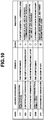
- Fig. 10 shows the study trends of conventional time synchronization techniques (see non-patent literature 1 and the like).
- the accuracy of the time stamp of the data collection terminal is very high because, according to the synchronization method described in non-patent literature 1, synchronization can be applied to the upper network at a level to 1 ms or less. However, if a packet loss occurs, it can be estimated only from time. If a transmission delay occurs, the delay causes an error in the time stamp.
- Non-Patent Literature 1 Makoto Suzuki, “Research Trends of Time Synchronization Technologies in Wireless Sensor Networks", The University of Tokyo, Research Center for Advanced Science and Technology, Morikawa Laboratory, Technical Research Report, No. 2008001, April 24, 2008 .
- the present invention has been made to solve the above-described problems, and has as its object to provide a time stamp correction technique of allowing a data collection terminal to obtain a time stamp with little error concerning sensor data without imparting a sophisticated clock function to a sensor terminal.
- a sensing system including a sensor terminal that stores measured sensor data in a packet and wirelessly transmits the packet, and a data collection terminal that collects the sensor data by receiving the packet and transfers the sensor data to an upper network
- the sensor terminal comprises a real-time clock circuit that counts, by a counter, a sensor clock generated by the sensor terminal itself, and thereby outputs a count value that repeats a monotonous change within a predetermined numerical value range, and a sensor control circuit that periodically transmits the packet in synchronism with the change in the count value, and transmits the count value by adding the count value to the packet
- the data collection terminal comprises a reference clock generation circuit that generates a reference clock synchronized with a reference time acquired from the upper network, and a collection control circuit that acquires a value of the reference clock from the reference clock generation circuit in accordance with reception of the packet, and stores the value in a storage circuit as a time stamp representing an arrival time of the packet, and the
- a time stamp correction method used in a sensing system including a sensor terminal that stores measured sensor data in a packet and periodically wirelessly transmits the packet, and a data collection terminal that receives the packet, collects the sensor data, and transfers the sensor data to an upper network, comprising the steps of, by a real-time clock circuit of the sensor terminal, counting, by an incremental counter, a sensor clock generated by the sensor terminal itself, thereby outputting a count value that repeats a monotonous increment within a predetermined numerical value range, by a sensor control circuit of the sensor terminal, transmitting the packet in synchronism with the change in the count value, and adding the count value to the packet and transmitting the packet, by a reference clock generation circuit of the data collection terminal, generating a reference clock synchronized with a reference time acquired from the upper network, by a collection control circuit of the data collection terminal, acquiring a value of the reference clock from the reference clock generation circuit in accordance with reception of the packet and storing the value in a storage
- the data collection terminal can obtain a time stamp with little error concerning sensor data without imparting a high-performance clock function capable of counting time information or calendar information to the sensor terminal.
- the circuit arrangement of the sensor terminal can largely be simplified, and the cost of the entire sensing system can be reduced.
- the power consumption of the sensor terminal can be reduced, and the battery life can greatly be prolonged.
- a sensing system 1 according to the first embodiment of the present invention will be described first with reference to Fig. 1 .
- the sensing system 1 is formed by a plurality of sensor terminals 20 configured to store, in packets, sensor data obtained by measuring various kinds of physical amounts by sensors and wirelessly transmit the packets, and a data collection terminal 10 configured to receive the packets from the sensor terminals 20, collect the sensor data, and transfer the sensor data to a host device 30 of an upper network NW.
- the sensor terminal 20 includes, as main components, a sensor circuit 21, a real-time clock circuit 22, a wireless communication circuit 23, a storage circuit 24, and a sensor control circuit 25.
- the sensor circuit 21 is a sensor that measures various kinds of physical amounts.
- sensors configured to measure physical states or operations, for example, body temperature, blood pressure, pulse, and acceleration sensors are used.
- the sensors are not limited to these, as a matter of course.
- the real-time clock circuit 22 is a circuit portion that counts, by a counter, sensor clocks generated in the sensor terminal 20, and outputs an obtained count value. Since the counter counts the input sensor clocks one by one, the obtained count value repeats a monotonous change within a predetermined numerical value range corresponding to the bit width of the counter.
- the counter is formed by an incremental counter, and the count value is monotonously incremented one by one will be described as an example.
- a decremental counter may be used. In this case, the count value is monotonously decremented one by one.
- the wireless communication circuit 23 is a circuit portion that performs wireless communication with the data collection terminal 10.
- the storage circuit 24 is a semiconductor memory that stores various kinds of processing data used for measurement and transmission of sensor data.
- the sensor control circuit 25 is formed by an arithmetic processing unit formed by making a microprocessor such as a CPU/MPU and a program cooperate with each other, and has a function of storing, in a packet, sensor data representing a measurement result from the sensor circuit 21 and periodically transmitting the packet from the wireless communication circuit 23 to the data collection terminal 10 in synchronism with a change in the count value output from the real-time clock circuit 22, that is, in synchronism with one increment, and a function of, when transmitting the packet, adding the count value acquired from the real-time clock circuit 22 to the packet and transmitting the packet.
- a microprocessor such as a CPU/MPU and a program cooperate with each other
- the data collection terminal 10 includes, as main components, a wireless communication circuit 11, a reference clock generation circuit 12, a storage circuit 13, and a collection control circuit 14.
- the wireless communication circuit 11 is a circuit portion that that performs wireless communication with the sensor terminal 20.
- the reference clock generation circuit 12 is a circuit portion that outputs a reference clock based on, for example, time information acquired from a time server on the upper network NW.
- the storage circuit 13 is a semiconductor memory that stores a time stamp representing the arrival time of a packet that the wireless communication circuit 11 has received from the sensor terminal 20.
- the collection control circuit 14 is formed by an arithmetic processing unit formed by making a microprocessor such as a CPU/MPU and a program cooperate with each other, and has a function of acquiring a reference clock from the reference clock generation circuit 12 every time the wireless communication circuit 11 receives a packet from the sensor terminal 20 and storing the reference clock in the storage circuit 13 as a time stamp representing the arrival time of the packet received, and a function of performing statistical processing of count values added to a plurality of packets received and the time stamps of these packets read out from the storage circuit 13 to estimate an initial arrival time representing the arrival time of a head packet that is the first of these packets received and a packet transmission interval representing the transmission interval of these packets.
- a microprocessor such as a CPU/MPU and a program cooperate with each other
- the collection control circuit 14 has a function of recalculating the time stamps concerning the packets based on the estimated values of the initial arrival time and the packet transmission interval to correct the time stamp added at the time of packet reception, and a function of transferring the set of the sensor data and the time stamps to the host device 30.
- the time stamp generally includes not only time information but also calendar information because the time stamp is based on the reference time of the upper network NW, for example, the UNIX time. This allows the host device 30 to acquire time information and calendar information concerning sensor data even if the sensor terminal 20 does not have a clock function of counting overall time information or calendar information and includes only a counter of a simple arrangement.
- the collection control circuit 14 of the data collection terminal 10 preferably includes a microprocessor with a high calculation capability because it needs to perform statistical processing of heavy processing load.
- the reference clock generation circuit 12 need only implement a known time synchronization method such as a time synchronization method described in, for example, non-patent literature 1 to establish synchronization with the reference time of the upper network NW.
- a microprocessor of high performance need not be selected because the sensor control circuit 25 only adds the count value of the incremental counter to the packet of acquired sensor data.
- the sensor control circuit 25 of the sensor terminal 20 stores sensor data measured by the sensor circuit 21 in a packet, and periodically transmits the packet from the wireless communication circuit 11 to the data collection terminal 10 at a predetermined transmission interval in synchronism with a change in a count value n of the incremental counter from the real-time clock circuit 22.
- the sensor control circuit 25 acquires the count value n from the real-time clock circuit 22, adds the count value n to a packet P, and transmits the packet P.
- the transmission interval of the packet and the count operation of the incremental counter are in synchronism.
- the count value n is incremented one by one for subsequent packets P1, P2,....
- the count value n has a maximum value N max according to the bit width of the incremental counter. After reaching the maximum value N max , the count value n is reset to zero and then monotonously incremented again.
- the collection control circuit 14 of the data collection terminal 10 acquires a reference clock from the reference clock generation circuit 12 and stores it in the storage circuit 13 as a time stamp T representing the arrival time of the received packet.
- the reference clock generation circuit 12 generates the reference clock synchronized with the precise time of the upper network NW based on the time information that the collection control circuit 14 periodically acquires from an apparatus such as a time server on the upper network NW. Accordingly, the time stamp representing the precise arrival time of each packet is stored in the storage circuit 13.
- the transmission interval T packet becomes long, and therefore, the measurement estimated time t exhibits a characteristic 32 extended to the rear side with respect to an initial characteristic 31, as shown in Fig. 3(a) .
- the transmission interval T packet becomes short, and therefore, the measurement estimated time t exhibits a characteristic 34 contracted to the front side with respect to an initial characteristic 33, as shown in Fig. 3(a) .
- the initial arrival time To may have an error.
- N max packets P from the head packet Po to a packet P Nmax-1 are received, and the time stamp of a packet P k (k is an integer from 0 to N max-1 ) is represented by T k .
- the transmission interval T packet is estimated by equation (2), and the initial arrival time T 0 is estimated by equation (3).
- the estimated values of the transmission interval T packet and the initial arrival time T 0 average errors caused by the transmission delay included in these, the processing priority in the microprocessor, and the like, the error included in the time stamp can be reduced.
- the time stamp of each sensor data can accurately be estimated, that is, recalculated, and the time stamp added at the time of packet reception can be corrected. This is particularly useful in a sensing application that needs a relatively high sampling rate for an acceleration or a voltage waveform.
- the UNIX® time is used as the reference time.
- the UNIX time is accurate, variations in the low latitudes of a normal distribution exist with respect to the trend. Hence, when the present invention is applied, the gradient can correctly be measured.
- the graph of Fig. 5 shows a measurement result obtained by experimentarily measuring the frequency distribution of time stamp intervals of packets when the data collection terminal 10 receives packets parallelly transmitted from the plurality of sensor terminals 20 at a predetermined interval of 40 ms.
- the reliable section width of ⁇ 3 ⁇ is 250 ⁇ s, as shown in Fig. 6 .
- the time stamp interval falls within the reliable section of 40 ms ⁇ 125 ⁇ s at a probability of 99.7%, and shows a large effect by the time stamp correction according to this embodiment.
- the sensor control circuit 25 periodically transmits a packet in synchronism with a change in the count value from the real-time clock circuit 22, which is repetitively monotonously incremented within a predetermined numerical value range, and additionally acquires the count value, adds it to the packet, and transmits the packet.
- the collection control circuit 14 acquires, from the reference clock generation circuit 12, the value of the reference clock synchronized with the reference time of the upper network NW, stores the value in the storage circuit 13 as a time stamp representing the arrival time of the packet, performs statistical processing of time stamps and count values concerning a plurality of packets received, and corrects the time stamps concerning the packets based on the obtained packet transmission interval and the reference arrival time representing the arrival time of the head packet.
- the errors included in the estimated values of the transmission interval T packet and the initial arrival time T 0 are averaged. For this reason, when a time stamp is estimated based on these, an error included in the time stamp added at the time of packet reception can be reduced. Hence, the data collection terminal 10 can obtain a time stamp with little error concerning sensor data without imparting a high-performance clock function capable of counting time information or calendar information to the sensor terminal 20.
- the circuit arrangement of the sensor terminal 20 can largely be simplified, and the cost of the entire sensing system 1 can be reduced.
- the power consumption of the sensor terminal 20 can be reduced, and the battery life can greatly be prolonged.
- the time stamp can be estimated based on the estimated values of the transmission interval T packet and the initial arrival time T 0 . Hence, even if a packet loss occurs between the sensor terminal 20 and the data collection terminal 10, sensor data can be measured and corrected based on the correct reference time synchronized with the upper network NW.
- a sensing system 1 according to the second embodiment of the present invention will be described next.
- the method using the least square method using the value n from 0 to N max which has been described in the first embodiment, has a very high accuracy.
- N max is a large value
- the time stamps of packets are not determined until all the data are obtained. This is particularly problematic in an application that requires real-time property.
- the cost for that is also problematic.
- a collection control circuit 14 of the data collection terminal 10 performs statistical processing using a number smaller than the maximum value of the count value as a constraint length concerning the number of packets used for statistical processing, thereby estimating a transmission interval T packet and an initial arrival time T 0 .
- the rest of the arrangement of the sensing system 1 according to this embodiment is the same as in the first embodiment, and a description thereof will be omitted here.
- a sensing system 1 according to the third embodiment of the present invention will be described next.
- a collection control circuit 14 reads out time stamps concerning packets received within the constraint length before the latest packet last received as target time stamps from a storage circuit 13, and performs statistical processing of the time stamps.
- the rest of the arrangement of the sensing system 1 according to this embodiment is the same as in the first embodiment, and a description thereof will be omitted here.
- the collection control circuit 14 stores a new time stamp in the storage circuit 13 in accordance with reception of a packet
- the new time stamp is stored successively from the beginning of the storage area provided in the storage circuit 13. If the number of time stamps has reached the constraint length, the oldest time stamp located at the beginning of the storage area is erased, the rest of the time stamps are shifted so as to be successively arranged from the beginning of the storage area, and the new time stamp is stored at the end of the storage area.
- the packets corresponding to the constraint length to be used for the statistical processing are used while being shifted (slid) one by one in each statistical processing. That is, a constraint length N' max used in the statistical processing is not changed.
- N' max used in the statistical processing
- T j+1 - T j ⁇ -T th holds for an integer satisfying 0 ⁇ j ⁇ i-N' max
- calculation is performed by adding T packet *N max to each of T j+1 , T j ,..., T i-N'max+1 .
- the threshold T th can be selected by an arbitrary method. When the threshold is set to almost N max /2 to prevent a time fluctuation or temporary packet loss caused by an error in the processing time or transmission time, a satisfactory operation can be performed.
- Fig. 7 shows a storage example of time stamps. Until the number of packets reaches N' max , the storage areas in the storage circuit 13 concerning time stamps are increased one by one to store new time stamps. After the number of packets reaches N' max , old time stamps are erased one by one successively in chronological order, the remaining time stamps are shifted, and a new time stamp is stored at the end.
- the number of packets is small, and the accuracy of estimated time stamps is unstable.
- the effect of averaging processing by the least square method is gradually exerted, and the estimation accuracy improves.
- the statistical processing is performed immediately after a new packet is received. Hence, the latency is reduced, and the real-time property improves.
Landscapes
- Engineering & Computer Science (AREA)
- Computer Networks & Wireless Communication (AREA)
- Signal Processing (AREA)
- Health & Medical Sciences (AREA)
- Computing Systems (AREA)
- General Health & Medical Sciences (AREA)
- Medical Informatics (AREA)
- Physics & Mathematics (AREA)
- General Physics & Mathematics (AREA)
- Arrangements For Transmission Of Measured Signals (AREA)
- Mobile Radio Communication Systems (AREA)
Abstract
Description
- The present invention relates to a time stamp correction technique for correcting a time stamp concerning sensor data wirelessly transmitted from a sensor terminal and received by a data collection terminal.
- In an IoT (Internet of Things) society in which all things are connected to the Internet, it is expected that various kinds of sensors are connected to networks, a large amount of various kinds of data are collected, and information useful for humans is extracted by analyzing the data.
Fig. 8 shows an example of the arrangement of a sensor network used in the IoT. Under such circumstances, terminals that store sensors are required to cope with various use cases and needs, and a problem may arise in operation only with smartphones as the current mainstream. - In particular, it is difficult to connect a number of smartphones simultaneously. As a measure against this, the network of sensor storing terminals is configured as a tree type so that the number of smartphones to be connected can be expected to increase.
Fig. 9 shows an example of the arrangement of a general sensor network. In particular, BLE (Bluetooth Low Energy) formed by extending Bluetooth® that is one of short distance wireless communication techniques enables communication with very low power, and is therefore very useful as a wireless communication method between a sensor and a sensor storing terminal. - However, when this method is employed, time stamps are often added by a data collection terminal (slave). If there is a time shift between a slave and a master, a reference time concerning sensing is unclear. Hence, various time synchronization methods have been proposed conventionally.
Fig. 10 shows the study trends of conventional time synchronization techniques (seenon-patent literature 1 and the like). - In this conventional technique, however, when adding a time stamp by a data collection terminal, a delay time concerning communication between a sensor and the data collection terminal cannot be canceled, and an error is always generated in the time stamp. On the other hand, there also exist cases in which a sensor is provided with a simple time stamp mechanism using an incremental counter that is incremented at a predetermined period. In many cases, an oscillator of low accuracy is used to reduce the cost of the sensor device, and an error occurs.
- That is, when a time stamp is added by the simple time stamp mechanism provided in the sensor, monotony is guaranteed by the incremental counter. For this reason, even when a packet loss occurs in which data does not arrive at the data collection terminal, this can be recognized by referring to the incremental counter. On the other hand, the accuracy is low, and an error of several seconds occurs in one day. In particular, in a wearable device configured to perform measurement on a daily basis, the results do not match.
- To the contrary, the accuracy of the time stamp of the data collection terminal is very high because, according to the synchronization method described in
non-patent literature 1, synchronization can be applied to the upper network at a level to 1 ms or less. However, if a packet loss occurs, it can be estimated only from time. If a transmission delay occurs, the delay causes an error in the time stamp. - Non-Patent Literature 1: Makoto Suzuki, "Research Trends of Time Synchronization Technologies in Wireless Sensor Networks", The University of Tokyo, Research Center for Advanced Science and Technology, Morikawa Laboratory, Technical Research Report, No. 2008001, April 24, 2008.
- The present invention has been made to solve the above-described problems, and has as its object to provide a time stamp correction technique of allowing a data collection terminal to obtain a time stamp with little error concerning sensor data without imparting a sophisticated clock function to a sensor terminal. Means of Solution to the Problem
- In order to achieve the above object, according to the present invention, there is provided a sensing system including a sensor terminal that stores measured sensor data in a packet and wirelessly transmits the packet, and a data collection terminal that collects the sensor data by receiving the packet and transfers the sensor data to an upper network, wherein the sensor terminal comprises a real-time clock circuit that counts, by a counter, a sensor clock generated by the sensor terminal itself, and thereby outputs a count value that repeats a monotonous change within a predetermined numerical value range, and a sensor control circuit that periodically transmits the packet in synchronism with the change in the count value, and transmits the count value by adding the count value to the packet, the data collection terminal comprises a reference clock generation circuit that generates a reference clock synchronized with a reference time acquired from the upper network, and a collection control circuit that acquires a value of the reference clock from the reference clock generation circuit in accordance with reception of the packet, and stores the value in a storage circuit as a time stamp representing an arrival time of the packet, and the collection control circuit performs statistical processing of the time stamps concerning a plurality of packets received and count values added to the plurality of packets, and recalculates the time stamps concerning the packets based on an obtained packet transmission interval and a reference arrival time representing an arrival time of a head packet.
- According to the present invention, there is also provided a time stamp correction method used in a sensing system including a sensor terminal that stores measured sensor data in a packet and periodically wirelessly transmits the packet, and a data collection terminal that receives the packet, collects the sensor data, and transfers the sensor data to an upper network, comprising the steps of, by a real-time clock circuit of the sensor terminal, counting, by an incremental counter, a sensor clock generated by the sensor terminal itself, thereby outputting a count value that repeats a monotonous increment within a predetermined numerical value range, by a sensor control circuit of the sensor terminal, transmitting the packet in synchronism with the change in the count value, and adding the count value to the packet and transmitting the packet, by a reference clock generation circuit of the data collection terminal, generating a reference clock synchronized with a reference time acquired from the upper network, by a collection control circuit of the data collection terminal, acquiring a value of the reference clock from the reference clock generation circuit in accordance with reception of the packet and storing the value in a storage circuit as a time stamp representing an arrival time of the packet, and by the collection control circuit, performing statistical processing of the time stamps concerning a plurality of packets received and count values added to the plurality of packets, and recalculating the time stamps concerning the packets based on an obtained packet transmission interval and a reference arrival time representing an arrival time of a head packet.
- According to the present invention, errors included in the estimated values of the packet transmission interval and the initial arrival time are averaged. For this reason, when a time stamp is estimated based on these, an error included in the time stamp added at the time of reception can be reduced. Hence, the data collection terminal can obtain a time stamp with little error concerning sensor data without imparting a high-performance clock function capable of counting time information or calendar information to the sensor terminal. For this reason, the circuit arrangement of the sensor terminal can largely be simplified, and the cost of the entire sensing system can be reduced. In addition, the power consumption of the sensor terminal can be reduced, and the battery life can greatly be prolonged.
-
-
Fig. 1 is a block diagram showing the arrangement of a sensing system; -
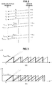
Fig. 2 is an explanatory view showing packet transmission; -
Fig. 3 is a graph showing the relationship between a time stamp and a measurement estimated time; -
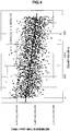
Fig. 4 is a graph showing a plot example of reference times for count values; -
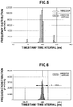
Fig. 5 is a graph showing the effect of time stamp correction according to this embodiment; -
Fig. 6 is a graph showing an enlarged main portion ofFig. 5 ; -
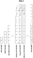
Fig. 7 is a view showing a storage example of time stamps; -
Fig. 8 is a view showing an example of the arrangement of a sensor network used in an IoT; -
Fig. 9 is a view showing an example of the arrangement of a general sensor network; -
Fig. 10 is a view showing the study trends of conventional time synchronization techniques. - Embodiments of the present invention will now be described with reference to the accompanying drawings.
- A
sensing system 1 according to the first embodiment of the present invention will be described first with reference toFig. 1 . - As shown in
Fig. 1 , thesensing system 1 is formed by a plurality ofsensor terminals 20 configured to store, in packets, sensor data obtained by measuring various kinds of physical amounts by sensors and wirelessly transmit the packets, and adata collection terminal 10 configured to receive the packets from thesensor terminals 20, collect the sensor data, and transfer the sensor data to ahost device 30 of an upper network NW. - The
sensor terminal 20 includes, as main components, asensor circuit 21, a real-time clock circuit 22, awireless communication circuit 23, astorage circuit 24, and asensor control circuit 25. - The
sensor circuit 21 is a sensor that measures various kinds of physical amounts. For example, in a sensing system that collects biological information of a human, sensors configured to measure physical states or operations, for example, body temperature, blood pressure, pulse, and acceleration sensors are used. However, the sensors are not limited to these, as a matter of course. - The real-
time clock circuit 22 is a circuit portion that counts, by a counter, sensor clocks generated in thesensor terminal 20, and outputs an obtained count value. Since the counter counts the input sensor clocks one by one, the obtained count value repeats a monotonous change within a predetermined numerical value range corresponding to the bit width of the counter. In this embodiment, a case in which the counter is formed by an incremental counter, and the count value is monotonously incremented one by one will be described as an example. A decremental counter may be used. In this case, the count value is monotonously decremented one by one. - The
wireless communication circuit 23 is a circuit portion that performs wireless communication with thedata collection terminal 10. - The
storage circuit 24 is a semiconductor memory that stores various kinds of processing data used for measurement and transmission of sensor data. - The
sensor control circuit 25 is formed by an arithmetic processing unit formed by making a microprocessor such as a CPU/MPU and a program cooperate with each other, and has a function of storing, in a packet, sensor data representing a measurement result from thesensor circuit 21 and periodically transmitting the packet from thewireless communication circuit 23 to thedata collection terminal 10 in synchronism with a change in the count value output from the real-time clock circuit 22, that is, in synchronism with one increment, and a function of, when transmitting the packet, adding the count value acquired from the real-time clock circuit 22 to the packet and transmitting the packet. - The
data collection terminal 10 includes, as main components, awireless communication circuit 11, a referenceclock generation circuit 12, astorage circuit 13, and acollection control circuit 14. - The
wireless communication circuit 11 is a circuit portion that that performs wireless communication with thesensor terminal 20. - The reference
clock generation circuit 12 is a circuit portion that outputs a reference clock based on, for example, time information acquired from a time server on the upper network NW. - The
storage circuit 13 is a semiconductor memory that stores a time stamp representing the arrival time of a packet that thewireless communication circuit 11 has received from thesensor terminal 20. - The
collection control circuit 14 is formed by an arithmetic processing unit formed by making a microprocessor such as a CPU/MPU and a program cooperate with each other, and has a function of acquiring a reference clock from the referenceclock generation circuit 12 every time thewireless communication circuit 11 receives a packet from thesensor terminal 20 and storing the reference clock in thestorage circuit 13 as a time stamp representing the arrival time of the packet received, and a function of performing statistical processing of count values added to a plurality of packets received and the time stamps of these packets read out from thestorage circuit 13 to estimate an initial arrival time representing the arrival time of a head packet that is the first of these packets received and a packet transmission interval representing the transmission interval of these packets. - In addition, the
collection control circuit 14 has a function of recalculating the time stamps concerning the packets based on the estimated values of the initial arrival time and the packet transmission interval to correct the time stamp added at the time of packet reception, and a function of transferring the set of the sensor data and the time stamps to thehost device 30. The time stamp generally includes not only time information but also calendar information because the time stamp is based on the reference time of the upper network NW, for example, the UNIX time. This allows thehost device 30 to acquire time information and calendar information concerning sensor data even if thesensor terminal 20 does not have a clock function of counting overall time information or calendar information and includes only a counter of a simple arrangement. - Note that the
collection control circuit 14 of thedata collection terminal 10 preferably includes a microprocessor with a high calculation capability because it needs to perform statistical processing of heavy processing load. In addition, the referenceclock generation circuit 12 need only implement a known time synchronization method such as a time synchronization method described in, for example,non-patent literature 1 to establish synchronization with the reference time of the upper network NW. - On the other hand, for the
sensor control circuit 25 of thesensor terminal 20, a microprocessor of high performance need not be selected because thesensor control circuit 25 only adds the count value of the incremental counter to the packet of acquired sensor data. The lower the operating frequency is, the smaller the power consumption is. For this reason, a microprocessor with an operating frequency of, for example, 50 MHz or less may be used. - The operation of the
sensing system 1 according to this embodiment will be described next with reference toFig. 2 . - As shown in
Fig. 2 , thesensor control circuit 25 of thesensor terminal 20 stores sensor data measured by thesensor circuit 21 in a packet, and periodically transmits the packet from thewireless communication circuit 11 to thedata collection terminal 10 at a predetermined transmission interval in synchronism with a change in a count value n of the incremental counter from the real-time clock circuit 22. At this time, thesensor control circuit 25 acquires the count value n from the real-time clock circuit 22, adds the count value n to a packet P, and transmits the packet P. - In the example shown in
Fig. 2 , the transmission interval of the packet and the count operation of the incremental counter are in synchronism. The count value n is monotonously incremented one by one for each transmitted packet. For this reason, a head packet P0 transmitted first has the count value n = 0. The count value n is incremented one by one for subsequent packets P1, P2,.... The count value n has a maximum value Nmax according to the bit width of the incremental counter. After reaching the maximum value Nmax, the count value n is reset to zero and then monotonously incremented again. - On the other hand, every time the
wireless communication circuit 11 receives the packet from thesensor terminal 20, thecollection control circuit 14 of thedata collection terminal 10 acquires a reference clock from the referenceclock generation circuit 12 and stores it in thestorage circuit 13 as a time stamp T representing the arrival time of the received packet. - The reference
clock generation circuit 12 generates the reference clock synchronized with the precise time of the upper network NW based on the time information that thecollection control circuit 14 periodically acquires from an apparatus such as a time server on the upper network NW. Accordingly, the time stamp representing the precise arrival time of each packet is stored in thestorage circuit 13. - As shown in
Fig. 3 that is a graph showing the relationship between the time stamp and the measurement estimated time, in a case in which a count value i added to a packet is incremented one by one for each packet, letting T0 be the initial arrival time that is the arrival time of the head packet P0 in thedata collection terminal 10, and Tpacket be the transmission interval of the packet P, a time stamp t concerning a certain packet Pi whose count value is i is obtained by
- However, if the sensor clock of the
sensor terminal 20 is later than the reference, the transmission interval Tpacket becomes long, and therefore, the measurement estimated time t exhibits a characteristic 32 extended to the rear side with respect to an initial characteristic 31, as shown inFig. 3(a) . On the other hand, if the sensor clock of thesensor terminal 20 is earlier than the reference, the transmission interval Tpacket becomes short, and therefore, the measurement estimated time t exhibits a characteristic 34 contracted to the front side with respect to an initial characteristic 33, as shown inFig. 3(a) . In addition, since a transmission delay from thesensor terminal 20 to thedata collection terminal 10 exists, the initial arrival time To may have an error. - In the present invention, statistical processing of time stamps and count values concerning a plurality of packets is performed, thereby reducing the error included in the time stamp of each sensor data.
- Assume that Nmax packets P from the head packet Po to a packet PNmax-1 are received, and the time stamp of a packet Pk (k is an integer from 0 to Nmax-1) is represented by Tk. In this case, based on the least square method, the transmission interval Tpacket is estimated by equation (2), and the initial arrival time T0 is estimated by equation (3).


- Since the estimated values of the transmission interval Tpacket and the initial arrival time T0 average errors caused by the transmission delay included in these, the processing priority in the microprocessor, and the like, the error included in the time stamp can be reduced. Hence, when the obtained estimated values of the transmission interval Tpacket and the initial arrival time T0 are applied to equation (1) described above, the time stamp of each sensor data can accurately be estimated, that is, recalculated, and the time stamp added at the time of packet reception can be corrected. This is particularly useful in a sensing application that needs a relatively high sampling rate for an acceleration or a voltage waveform.
- In a plot example of reference times for count values shown in
Fig. 4 , the UNIX® time is used as the reference time. Although the UNIX time is accurate, variations in the low latitudes of a normal distribution exist with respect to the trend. Hence, when the present invention is applied, the gradient can correctly be measured. - The graph of
Fig. 5 shows a measurement result obtained by experimentarily measuring the frequency distribution of time stamp intervals of packets when thedata collection terminal 10 receives packets parallelly transmitted from the plurality ofsensor terminals 20 at a predetermined interval of 40 ms. - In a case of non-application in which time stamp correction is not applied, variations to 20 ms or 60 ms occur with respect to the actual interval of 40 ms as the center, as can be seen. Probable reasons are an error caused by a delay time concerning communication between the
sensor terminal 20 and thedata collection terminal 10, and a processing delay derived from a processing load needed for reception processing of the packets transmitted in parallel. - On the other hand, when the time stamp correction according to this embodiment is applied, as for the time stamp interval of packets received, the reliable section width of ±3σ is 250 µs, as shown in
Fig. 6 . This means that the time stamp interval falls within the reliable section of 40 ms ± 125 µs at a probability of 99.7%, and shows a large effect by the time stamp correction according to this embodiment. - As described above, in this embodiment, in the
sensor terminal 20, thesensor control circuit 25 periodically transmits a packet in synchronism with a change in the count value from the real-time clock circuit 22, which is repetitively monotonously incremented within a predetermined numerical value range, and additionally acquires the count value, adds it to the packet, and transmits the packet. In thedata collection terminal 10, in response to packet reception, thecollection control circuit 14 acquires, from the referenceclock generation circuit 12, the value of the reference clock synchronized with the reference time of the upper network NW, stores the value in thestorage circuit 13 as a time stamp representing the arrival time of the packet, performs statistical processing of time stamps and count values concerning a plurality of packets received, and corrects the time stamps concerning the packets based on the obtained packet transmission interval and the reference arrival time representing the arrival time of the head packet. - Accordingly, the errors included in the estimated values of the transmission interval Tpacket and the initial arrival time T0 are averaged. For this reason, when a time stamp is estimated based on these, an error included in the time stamp added at the time of packet reception can be reduced. Hence, the
data collection terminal 10 can obtain a time stamp with little error concerning sensor data without imparting a high-performance clock function capable of counting time information or calendar information to thesensor terminal 20. - For this reason, the circuit arrangement of the
sensor terminal 20 can largely be simplified, and the cost of theentire sensing system 1 can be reduced. In addition, the power consumption of thesensor terminal 20 can be reduced, and the battery life can greatly be prolonged. - Furthermore, the time stamp can be estimated based on the estimated values of the transmission interval Tpacket and the initial arrival time T0. Hence, even if a packet loss occurs between the
sensor terminal 20 and thedata collection terminal 10, sensor data can be measured and corrected based on the correct reference time synchronized with the upper network NW. - A
sensing system 1 according to the second embodiment of the present invention will be described next. - The method using the least square method using the value n from 0 to Nmax, which has been described in the first embodiment, has a very high accuracy. However, if Nmax is a large value, the time stamps of packets are not determined until all the data are obtained. This is particularly problematic in an application that requires real-time property. In addition, since a large memory area corresponding to Nmax is necessary in a
data collection terminal 10, the cost for that is also problematic. - In this embodiment, a
collection control circuit 14 of thedata collection terminal 10 performs statistical processing using a number smaller than the maximum value of the count value as a constraint length concerning the number of packets used for statistical processing, thereby estimating a transmission interval Tpacket and an initial arrival time T0. The rest of the arrangement of thesensing system 1 according to this embodiment is the same as in the first embodiment, and a description thereof will be omitted here. - As described above, when calculation is performed using a unique constraint length N'max that satisfies 1 < N'max < Nmax, it is possible to improve the real-time property, decrease the capacity of the time stamp accumulation memory in the
data collection terminal 10, and reduce the cost. - As for how to select the value N'max, letting M be an arbitrary integer, a value with which N'max + 1 = Nmax/M is an integer is preferably selected. This is a contrivance to prevent the influence of a change in the value, which is caused when n returns from Nmax to 0. Since N'max+1 is generally a multiplier of 2 because of the characteristic of the MPU, a multiplier of 2 can be selected as M almost without any problem.
- A
sensing system 1 according to the third embodiment of the present invention will be described next. - In the above-described second embodiment, since estimation does not end unless data corresponding to the constraint length N'max is wholly obtained, there is still the problem of real-time property.
- In this embodiment, at the time of statistical processing, a
collection control circuit 14 reads out time stamps concerning packets received within the constraint length before the latest packet last received as target time stamps from astorage circuit 13, and performs statistical processing of the time stamps. The rest of the arrangement of thesensing system 1 according to this embodiment is the same as in the first embodiment, and a description thereof will be omitted here. - At this time, more specifically, when the
collection control circuit 14 stores a new time stamp in thestorage circuit 13 in accordance with reception of a packet, if the number of already stored time stamps is less than the constraint length, the new time stamp is stored successively from the beginning of the storage area provided in thestorage circuit 13. If the number of time stamps has reached the constraint length, the oldest time stamp located at the beginning of the storage area is erased, the rest of the time stamps are shifted so as to be successively arranged from the beginning of the storage area, and the new time stamp is stored at the end of the storage area. - In addition, at the time of statistical processing, all time stamps stored in the storage area are read out as target time stamps from the
storage circuit 13, and statistical processing is performed. - Accordingly, the packets corresponding to the constraint length to be used for the statistical processing are used while being shifted (slid) one by one in each statistical processing. That is, a constraint length N'max used in the statistical processing is not changed. To estimate the parameter of an ith packet, ith, (i-1)th, (i-2)th, ..., (i-N'max+1)th packets are used.
- In this case, a transmission interval Tpacket is estimated by equation (4), and an initial arrival time T0 is estimated by equation (5).


- In this method, however, since an error occurs when n changes from Nmax to 0, this needs to be corrected. As the correction method, if Tj+1 - Tj < -Tth holds for an integer satisfying 0 < j < i-N'max, calculation is performed by adding Tpacket*Nmax to each of Tj+1, Tj,..., Ti-N'max+1. The threshold Tth can be selected by an arbitrary method. When the threshold is set to almost Nmax/2 to prevent a time fluctuation or temporary packet loss caused by an error in the processing time or transmission time, a satisfactory operation can be performed.
- To the contrary, a time difference more than this means disconnection.
Fig. 7 shows a storage example of time stamps. Until the number of packets reaches N'max, the storage areas in thestorage circuit 13 concerning time stamps are increased one by one to store new time stamps. After the number of packets reaches N'max, old time stamps are erased one by one successively in chronological order, the remaining time stamps are shifted, and a new time stamp is stored at the end. - According to this method, at the beginning of packet reception, the number of packets is small, and the accuracy of estimated time stamps is unstable. As the number of packets approaches N'max, the effect of averaging processing by the least square method is gradually exerted, and the estimation accuracy improves. In addition, when the number of packets reaches N'max, the statistical processing is performed immediately after a new packet is received. Hence, the latency is reduced, and the real-time property improves.
- The present invention has been described above with reference to the exemplary embodiments. However, the present invention is not limited to the above exemplary embodiments. Various changes and modifications understandable by those who are skilled in the art can be done for the arrangements and details of the present invention without departing the scope of the present invention. In addition, the embodiments can be arbitrary combined and implemented without inconsistency.
- 1...sensing system, 10...data collection terminal, 11...wireless communication circuit, 12...reference clock generation circuit, 13...storage circuit, 14...collection control circuit, 20...sensor terminal, 21...sensor circuit, 22...real-time clock circuit, 23...wireless communication circuit, 24...storage circuit, 25...sensor control circuit, 30...host device, NW...upper network
Claims (5)
- A sensing system including a sensor terminal that stores measured sensor data in a packet and wirelessly transmits the packet, and a data collection terminal that collects the sensor data by receiving the packet and transfers the sensor data to an upper network, wherein
the sensor terminal comprises:a real-time clock circuit that counts, by a counter, a sensor clock generated by the sensor terminal itself, and thereby outputs a count value that repeats a monotonous change within a predetermined numerical value range; anda sensor control circuit that periodically transmits the packet in synchronism with the change in the count value, and transmits the count value by adding the count value to the packet, andthe data collection terminal comprises:a reference clock generation circuit that generates a reference clock synchronized with a reference time acquired from the upper network; anda collection control circuit that acquires a value of the reference clock from the reference clock generation circuit in accordance with reception of the packet, and stores the value in a storage circuit as a time stamp representing an arrival time of the packet,wherein the collection control circuit performs statistical processing of time stamps concerning a plurality of packets received and count values added to the plurality of packets, and recalculates the time stamps concerning the packets based on a packet transmission interval obtained from the statistical processing and a reference arrival time representing an arrival time of a head packet. - The sensing system according to claim 1, wherein the collection control circuit uses a number which is larger than 1 and smaller than a maximum value of the count value as a constraint length concerning the number of packets used in the statistical processing.
- The sensing system according to claim 2, Wherein, when performing the statistical processing, the collection control circuit reads out time stamps concerning packets received within the constraint length before a latest packet last received as target time stamps from the storage circuit, and performs the statistical processing of the time stamps.
- The sensing system according to claim 2, Wherein, when storing a new time stamp in the storage circuit in accordance with reception of the packet, if the number of time stamps already stored is less than the constraint length, the collection control circuit stores the new time stamp successively from a beginning of a storage area provided in the storage circuit, and if the number of time stamps has reached the constraint length, the collection control circuit erases an oldest time stamp located at the beginning of the storage area, shifts the rest of the time stamps so as to be arranged successively from the beginning of the storage area, and then stores the new time stamp at an end of the storage area, and when performing the statistical processing, the collection control circuit reads out all the time stamps stored in the storage area as target time stamps from the storage circuit, and performs the statistical processing of the time stamps.
- A time stamp correction method used in a sensing system including a sensor terminal that stores measured sensor data in a packet and periodically wirelessly transmits the packet, and a data collection terminal that receives the packet, collects the sensor data, and transfers the sensor data to an upper network, the time stamp correction method comprising the steps of:by a real-time clock circuit of the sensor terminal, counting, by an incremental counter, a sensor clock generated by the sensor terminal itself, thereby outputting a count value that repeats a monotonous increment within a predetermined numerical value range;by a sensor control circuit of the sensor terminal, transmitting the packet in synchronism with the change in the count value, and transmitting the count value by adding the count value to the packet;by a reference clock generation circuit of the data collection terminal, generating a reference clock synchronized with a reference time acquired from the upper network;by a collection control circuit of the data collection terminal, acquiring a value of the reference clock from the reference clock generation circuit in accordance with reception of the packet and storing the value in a storage circuit as a time stamp representing an arrival time of the packet; andby the collection control circuit, performing statistical processing of time stamps concerning a packets received and count values added to the plurality of packets, and recalculating the time stamps concerning the packets based on a packet transmission interval obtained from the statistical processing and a reference arrival time representing an arrivl time of a head packet.
Applications Claiming Priority (2)
| Application Number | Priority Date | Filing Date | Title |
|---|---|---|---|
| JP2017027820 | 2017-02-17 | ||
| PCT/JP2018/005224 WO2018151202A1 (en) | 2017-02-17 | 2018-02-15 | Sensing system and time stamp correction method |
Publications (3)
| Publication Number | Publication Date |
|---|---|
| EP3584780A1 true EP3584780A1 (en) | 2019-12-25 |
| EP3584780A4 EP3584780A4 (en) | 2020-11-04 |
| EP3584780B1 EP3584780B1 (en) | 2021-10-13 |
Family
ID=63170215
Family Applications (1)
| Application Number | Title | Priority Date | Filing Date |
|---|---|---|---|
| EP18754209.7A Active EP3584780B1 (en) | 2017-02-17 | 2018-02-15 | Sensing system and time stamp correction method |
Country Status (5)
| Country | Link |
|---|---|
| US (1) | US11284229B2 (en) |
| EP (1) | EP3584780B1 (en) |
| JP (1) | JP6649517B2 (en) |
| CN (1) | CN110337679B (en) |
| WO (1) | WO2018151202A1 (en) |
Families Citing this family (21)
| Publication number | Priority date | Publication date | Assignee | Title |
|---|---|---|---|---|
| DE102017217723A1 (en) * | 2017-10-05 | 2019-04-11 | Robert Bosch Gmbh | Apparatus and method for correcting at least one transmission parameter |
| CN114944910B (en) | 2017-10-30 | 2025-02-28 | 华为技术有限公司 | Clock synchronization method and device |
| JP7217153B2 (en) | 2019-01-10 | 2023-02-02 | 富士通株式会社 | Information processing device, time synchronization method, and time synchronization program |
| JP6672511B1 (en) * | 2019-07-09 | 2020-03-25 | 株式会社東芝 | Sensor system, transmission terminal, time information processing device, and synchronization method |
| EP3800486B1 (en) * | 2019-10-04 | 2024-06-26 | NXP USA, Inc. | Time of flight measurement for distance estimation with interference tolerance parameters |
| CN111132201B (en) * | 2020-01-09 | 2024-05-28 | 华南理工大学 | A wireless measurement system based on UWB |
| JP7318557B2 (en) * | 2020-02-18 | 2023-08-01 | トヨタ自動車株式会社 | Communication system, control method and control program |
| JP6878636B2 (en) * | 2020-02-21 | 2021-05-26 | 株式会社東芝 | Sensor system, transmission system, time information processing device and position positioning method |
| US11156705B2 (en) * | 2020-03-10 | 2021-10-26 | Raytheon Company | System and method for mitigating platform motion in a communications system |
| US11196497B2 (en) | 2020-03-11 | 2021-12-07 | Raytheon Company | System and method for mitigating platform motion in a communications system |
| CN112230712A (en) * | 2020-10-26 | 2021-01-15 | 上海感探号信息科技有限公司 | A time axis synchronization system and method for vehicle positioning |
| JP7452707B2 (en) * | 2020-12-08 | 2024-03-19 | 日本電信電話株式会社 | Measurement system, measurement method, measurement device, and program |
| US11632823B1 (en) | 2021-03-23 | 2023-04-18 | Waymo Llc | Estimating sensor timestamps by oversampling |
| CN113188605B (en) * | 2021-05-12 | 2022-06-21 | 郑州大学 | Physical experiment method based on smart phone |
| US20240275512A1 (en) * | 2021-06-07 | 2024-08-15 | Nippon Telegraph And Telephone Corporation | Communication connection determination method, communication connection determination device and sensor system |
| WO2022259379A1 (en) * | 2021-06-08 | 2022-12-15 | 三菱電機株式会社 | Programmable logic controller, moving image management device, moving image management system, moving image management method, and program |
| CN113466522B (en) * | 2021-07-09 | 2022-04-19 | 电子科技大学 | A Dynamic Correction Method of Trigger Point Offset for Data Acquisition System |
| JP7700597B2 (en) | 2021-09-14 | 2025-07-01 | オムロン株式会社 | Information collection system and information collection method |
| WO2023105705A1 (en) * | 2021-12-09 | 2023-06-15 | 日本電信電話株式会社 | Timestamp correcting system, sensor system, and timestamp correcting method |
| CN116991201B (en) * | 2023-09-27 | 2023-12-22 | 博睿康科技(常州)股份有限公司 | Single device multiple physiological parameter synchronization method, acquisition system and data alignment method |
| US20260086908A1 (en) * | 2024-09-23 | 2026-03-26 | Sensus Spectrum, Llc | Handling of operational metrics in resource-limited devices and communication systems |
Family Cites Families (40)
| Publication number | Priority date | Publication date | Assignee | Title |
|---|---|---|---|---|
| US5941918A (en) * | 1997-07-30 | 1999-08-24 | Engelhard Corporation | Automotive on-board monitoring system for catalytic converter evaluation |
| US6563796B1 (en) * | 1998-03-18 | 2003-05-13 | Nippon Telegraph And Telephone Corporation | Apparatus for quality of service evaluation and traffic measurement |
| JP2000069093A (en) * | 1998-08-19 | 2000-03-03 | Nippon Telegr & Teleph Corp <Ntt> | Packet output timing control method and packet output timing control circuit |
| US6882637B1 (en) * | 1999-10-14 | 2005-04-19 | Nokia Networks Oy | Method and system for transmitting and receiving packets |
| EP1724960A4 (en) * | 2004-03-10 | 2008-03-05 | Mitsubishi Electric Corp | DATA RECEIVING DEVICE AND DATA RECEIVING METHOD |
| JP4522164B2 (en) * | 2004-06-25 | 2010-08-11 | 富士通株式会社 | Communication characteristic measuring method, measuring apparatus and computer program |
| CN100531126C (en) * | 2004-07-14 | 2009-08-19 | 日本电信电话株式会社 | Packet transfer method and transfer apparatus |
| KR101197280B1 (en) * | 2005-07-15 | 2012-11-05 | 삼성전자주식회사 | Time synchronizing method and apparatus based on time stamp |
| US7839897B2 (en) * | 2006-09-29 | 2010-11-23 | Agere Systems Inc. | Methods and apparatus for unidirectional timing message transport over packet networks |
| JP4560080B2 (en) | 2007-12-20 | 2010-10-13 | 日本電信電話株式会社 | Wireless terminal, time distribution system, and time distribution method |
| JP4475336B2 (en) * | 2008-02-08 | 2010-06-09 | ソニー株式会社 | Time stamp adding apparatus, time stamp adding method, and program |
| FR2930396A1 (en) * | 2008-04-21 | 2009-10-23 | Thomson Licensing Sas | TEMPORAL MARKING ASSOCIATED WITH SYNCHRONIZATION OF EQUIPMENT CONNECTED TO A NETWORK |
| CN101729180A (en) * | 2008-10-21 | 2010-06-09 | 华为技术有限公司 | Method and system for synchronizing precision clocks, and precision clock frequency/time synchronizing device |
| US9100135B2 (en) * | 2008-10-24 | 2015-08-04 | Telefonaktiebolaget L M Ericsson (Publ) | Method and device for packet network synchronization |
| JP5166203B2 (en) | 2008-10-24 | 2013-03-21 | 株式会社日立製作所 | Sensor network system, sensor node, and base station |
| WO2010051462A1 (en) * | 2008-10-31 | 2010-05-06 | Wi-Lan, Inc. | Multicast broadcast service controller |
| CN101741701B (en) * | 2008-11-12 | 2012-01-11 | 中兴通讯股份有限公司 | Synchronous dispatching method and synchronous dispatching device |
| CN101783779B (en) * | 2009-01-16 | 2014-07-16 | 华为技术有限公司 | Time synchronization method, device and system of xDSL |
| JP5479793B2 (en) * | 2009-07-16 | 2014-04-23 | 株式会社サイバー創研 | Method and apparatus for estimating one-way fluctuation delay time |
| CN102035794A (en) * | 2009-09-29 | 2011-04-27 | 中兴通讯股份有限公司 | Method and system for transmitting and receiving synchronizing sequence of multimedia broadcast multicast service |
| EP2534869A4 (en) * | 2010-02-12 | 2013-07-10 | Research In Motion Ltd | Methods and apparatus to perform measurements |
| GB2478328B (en) * | 2010-03-03 | 2015-07-01 | Advanced Risc Mach Ltd | Method, apparatus and trace module for generating timestamps |
| IT1399965B1 (en) * | 2010-03-15 | 2013-05-09 | St Microelectronics Srl | "SYSTEM TO SYNCHRONIZE THE OPERATION OF A CIRCUIT WITH A CONTROL SIGNAL, AND ITS INTEGRATED CIRCUIT" |
| US8942319B2 (en) * | 2010-04-08 | 2015-01-27 | Rambus Inc. | Partial response equalizer and related method |
| US8660110B2 (en) * | 2010-04-16 | 2014-02-25 | Simmonds Precision Products, Inc. | Reduced power synchronization of wireless devices |
| CN102355319B (en) * | 2011-08-17 | 2015-07-08 | 中国科学院深圳先进技术研究院 | Time synchronization method and system for wireless sensor network |
| KR20130123482A (en) * | 2012-05-03 | 2013-11-13 | 삼성전자주식회사 | Time stamp management method for data synchronizing and terminal thereof |
| CN104641589B (en) * | 2012-09-11 | 2018-10-16 | 三菱电机株式会社 | Correction parameter computing device and time synchronization system and correction parameter computational methods |
| DE102012222881A1 (en) * | 2012-12-12 | 2014-06-12 | Bayerische Motoren Werke Aktiengesellschaft | Method for assigning timestamps to received data packets |
| TWI485996B (en) * | 2012-12-17 | 2015-05-21 | Ind Tech Res Inst | Apparatus and method for enabling a passive optical network on supporting time synchronization |
| CN104023385B (en) * | 2013-02-28 | 2018-07-31 | 王胤 | A kind of wireless multi-hop ad hoc net method for synchronizing time based on parallel transmission |
| US20150127284A1 (en) * | 2013-11-03 | 2015-05-07 | Microsoft Corporation | Sensor Data Time Alignment |
| JP2015114290A (en) | 2013-12-13 | 2015-06-22 | オムロン株式会社 | Time correction device, measurement device, and time correction method |
| KR101789641B1 (en) * | 2014-01-13 | 2017-11-20 | 엘지전자 주식회사 | Apparatuses and methods for transmitting or receiving a broadcast content via one or more networks |
| CN104918319B (en) * | 2014-03-13 | 2018-01-16 | 北方工业大学 | A Clock Synchronization Simplified Information Interaction Method Applied to Wireless Sensor Networks |
| JP6663912B2 (en) * | 2015-04-13 | 2020-03-13 | ソニーセミコンダクタソリューションズ株式会社 | Receiving device, receiving method, and program |
| CN104968043B (en) * | 2015-04-29 | 2018-04-27 | 重庆邮电大学 | A kind of clock synchronizing frequency deviation estimating method suitable for WIA-PA network |
| US10015216B2 (en) * | 2015-08-06 | 2018-07-03 | Qualcomm Incorporated | Methods and systems for virtual conference system using personal communication devices |
| CN106028272B (en) * | 2016-07-25 | 2019-06-14 | 广东乐心医疗电子股份有限公司 | Time synchronization method and device based on distributed BLE communication protocol wireless sensing system |
| WO2018123857A1 (en) * | 2016-12-28 | 2018-07-05 | 日本電信電話株式会社 | Sensing system and time synchronization method |
-
2018
- 2018-02-15 WO PCT/JP2018/005224 patent/WO2018151202A1/en not_active Ceased
- 2018-02-15 JP JP2018568597A patent/JP6649517B2/en active Active
- 2018-02-15 EP EP18754209.7A patent/EP3584780B1/en active Active
- 2018-02-15 US US16/486,103 patent/US11284229B2/en active Active
- 2018-02-15 CN CN201880012651.9A patent/CN110337679B/en active Active
Also Published As
| Publication number | Publication date |
|---|---|
| JP6649517B2 (en) | 2020-02-19 |
| JPWO2018151202A1 (en) | 2019-11-07 |
| CN110337679A (en) | 2019-10-15 |
| CN110337679B (en) | 2021-12-31 |
| US20200236517A1 (en) | 2020-07-23 |
| EP3584780B1 (en) | 2021-10-13 |
| US11284229B2 (en) | 2022-03-22 |
| WO2018151202A1 (en) | 2018-08-23 |
| EP3584780A4 (en) | 2020-11-04 |
Similar Documents
| Publication | Publication Date | Title |
|---|---|---|
| EP3584780B1 (en) | Sensing system and time stamp correction method | |
| CN110249372B (en) | Sensing system and time synchronization method | |
| US10142088B2 (en) | Network clock skew estimation and calibration | |
| KR101340752B1 (en) | High-precision synchronisation method and system | |
| US9544211B2 (en) | Measuring apparatus and method | |
| US20040141526A1 (en) | Fast frequency adjustment method for synchronizing network clocks | |
| Asgarian et al. | BlueSync: Time synchronization in Bluetooth low energy with energy-efficient calculations | |
| EP2811672A1 (en) | Communication apparatus, communication system, and communication method for time synchronization | |
| US8700805B2 (en) | Method for synchronizing clocks in a communication network | |
| CN103516508A (en) | Method and system for correcting clock drift in one-way and two-way delay variation measurement | |
| JP6605863B2 (en) | Electronic device, method, program, and protection system | |
| JP2015114290A (en) | Time correction device, measurement device, and time correction method | |
| CN102638339B (en) | Method and device for realizing precision time synchronization | |
| CN101331736A (en) | Using Transit Time as a Method of Improving the Accuracy of Simple Network Time Protocol | |
| JP2007134873A (en) | High-precision time synchronization processing device and program thereof, and network congestion level warning device and program thereof | |
| CN113141225A (en) | Time synchronization method, device, storage medium and terminal | |
| US11349586B2 (en) | Time stamping method, time stamping apparatus and program | |
| JP6048102B2 (en) | Information processing system | |
| EP1756678B1 (en) | Measuring clock jitter | |
| CN114885414B (en) | A method for increasing time synchronization accuracy | |
| US12107748B2 (en) | Information processing device, non-transitory computer-readable storage medium, and information processing method | |
| JP2021504676A (en) | How to determine the distance between two nodes | |
| JP6893070B2 (en) | Information communication system | |
| CN113890664B (en) | Method for synchronizing data in body area network, detection terminal and computer readable storage medium | |
| KR20080080758A (en) | How to synchronize the time of the terminal |
Legal Events
| Date | Code | Title | Description |
|---|---|---|---|
| STAA | Information on the status of an ep patent application or granted ep patent |
Free format text: STATUS: THE INTERNATIONAL PUBLICATION HAS BEEN MADE |
|
| PUAI | Public reference made under article 153(3) epc to a published international application that has entered the european phase |
Free format text: ORIGINAL CODE: 0009012 |
|
| STAA | Information on the status of an ep patent application or granted ep patent |
Free format text: STATUS: REQUEST FOR EXAMINATION WAS MADE |
|
| 17P | Request for examination filed |
Effective date: 20190808 |
|
| AK | Designated contracting states |
Kind code of ref document: A1 Designated state(s): AL AT BE BG CH CY CZ DE DK EE ES FI FR GB GR HR HU IE IS IT LI LT LU LV MC MK MT NL NO PL PT RO RS SE SI SK SM TR |
|
| AX | Request for extension of the european patent |
Extension state: BA ME |
|
| DAV | Request for validation of the european patent (deleted) | ||
| DAX | Request for extension of the european patent (deleted) | ||
| A4 | Supplementary search report drawn up and despatched |
Effective date: 20201001 |
|
| RIC1 | Information provided on ipc code assigned before grant |
Ipc: H04L 7/00 20060101ALI20200925BHEP Ipc: G08C 17/02 20060101ALI20200925BHEP Ipc: G08C 15/06 20060101AFI20200925BHEP Ipc: H04J 3/06 20060101ALI20200925BHEP Ipc: H04W 56/00 20090101ALI20200925BHEP Ipc: G08C 15/00 20060101ALI20200925BHEP Ipc: H04W 4/38 20180101ALI20200925BHEP |
|
| GRAP | Despatch of communication of intention to grant a patent |
Free format text: ORIGINAL CODE: EPIDOSNIGR1 |
|
| STAA | Information on the status of an ep patent application or granted ep patent |
Free format text: STATUS: GRANT OF PATENT IS INTENDED |
|
| INTG | Intention to grant announced |
Effective date: 20210528 |
|
| GRAS | Grant fee paid |
Free format text: ORIGINAL CODE: EPIDOSNIGR3 |
|
| GRAA | (expected) grant |
Free format text: ORIGINAL CODE: 0009210 |
|
| STAA | Information on the status of an ep patent application or granted ep patent |
Free format text: STATUS: THE PATENT HAS BEEN GRANTED |
|
| AK | Designated contracting states |
Kind code of ref document: B1 Designated state(s): AL AT BE BG CH CY CZ DE DK EE ES FI FR GB GR HR HU IE IS IT LI LT LU LV MC MK MT NL NO PL PT RO RS SE SI SK SM TR |
|
| REG | Reference to a national code |
Ref country code: GB Ref legal event code: FG4D |
|
| REG | Reference to a national code |
Ref country code: CH Ref legal event code: EP |
|
| REG | Reference to a national code |
Ref country code: DE Ref legal event code: R096 Ref document number: 602018025035 Country of ref document: DE |
|
| REG | Reference to a national code |
Ref country code: IE Ref legal event code: FG4D |
|
| REG | Reference to a national code |
Ref country code: AT Ref legal event code: REF Ref document number: 1438754 Country of ref document: AT Kind code of ref document: T Effective date: 20211115 |
|
| REG | Reference to a national code |
Ref country code: LT Ref legal event code: MG9D |
|
| REG | Reference to a national code |
Ref country code: NL Ref legal event code: MP Effective date: 20211013 |
|
| REG | Reference to a national code |
Ref country code: AT Ref legal event code: MK05 Ref document number: 1438754 Country of ref document: AT Kind code of ref document: T Effective date: 20211013 |
|
| PG25 | Lapsed in a contracting state [announced via postgrant information from national office to epo] |
Ref country code: RS Free format text: LAPSE BECAUSE OF FAILURE TO SUBMIT A TRANSLATION OF THE DESCRIPTION OR TO PAY THE FEE WITHIN THE PRESCRIBED TIME-LIMIT Effective date: 20211013 Ref country code: LT Free format text: LAPSE BECAUSE OF FAILURE TO SUBMIT A TRANSLATION OF THE DESCRIPTION OR TO PAY THE FEE WITHIN THE PRESCRIBED TIME-LIMIT Effective date: 20211013 Ref country code: FI Free format text: LAPSE BECAUSE OF FAILURE TO SUBMIT A TRANSLATION OF THE DESCRIPTION OR TO PAY THE FEE WITHIN THE PRESCRIBED TIME-LIMIT Effective date: 20211013 Ref country code: BG Free format text: LAPSE BECAUSE OF FAILURE TO SUBMIT A TRANSLATION OF THE DESCRIPTION OR TO PAY THE FEE WITHIN THE PRESCRIBED TIME-LIMIT Effective date: 20220113 Ref country code: AT Free format text: LAPSE BECAUSE OF FAILURE TO SUBMIT A TRANSLATION OF THE DESCRIPTION OR TO PAY THE FEE WITHIN THE PRESCRIBED TIME-LIMIT Effective date: 20211013 |
|
| PG25 | Lapsed in a contracting state [announced via postgrant information from national office to epo] |
Ref country code: IS Free format text: LAPSE BECAUSE OF FAILURE TO SUBMIT A TRANSLATION OF THE DESCRIPTION OR TO PAY THE FEE WITHIN THE PRESCRIBED TIME-LIMIT Effective date: 20220213 Ref country code: SE Free format text: LAPSE BECAUSE OF FAILURE TO SUBMIT A TRANSLATION OF THE DESCRIPTION OR TO PAY THE FEE WITHIN THE PRESCRIBED TIME-LIMIT Effective date: 20211013 Ref country code: PT Free format text: LAPSE BECAUSE OF FAILURE TO SUBMIT A TRANSLATION OF THE DESCRIPTION OR TO PAY THE FEE WITHIN THE PRESCRIBED TIME-LIMIT Effective date: 20220214 Ref country code: PL Free format text: LAPSE BECAUSE OF FAILURE TO SUBMIT A TRANSLATION OF THE DESCRIPTION OR TO PAY THE FEE WITHIN THE PRESCRIBED TIME-LIMIT Effective date: 20211013 Ref country code: NO Free format text: LAPSE BECAUSE OF FAILURE TO SUBMIT A TRANSLATION OF THE DESCRIPTION OR TO PAY THE FEE WITHIN THE PRESCRIBED TIME-LIMIT Effective date: 20220113 Ref country code: NL Free format text: LAPSE BECAUSE OF FAILURE TO SUBMIT A TRANSLATION OF THE DESCRIPTION OR TO PAY THE FEE WITHIN THE PRESCRIBED TIME-LIMIT Effective date: 20211013 Ref country code: LV Free format text: LAPSE BECAUSE OF FAILURE TO SUBMIT A TRANSLATION OF THE DESCRIPTION OR TO PAY THE FEE WITHIN THE PRESCRIBED TIME-LIMIT Effective date: 20211013 Ref country code: HR Free format text: LAPSE BECAUSE OF FAILURE TO SUBMIT A TRANSLATION OF THE DESCRIPTION OR TO PAY THE FEE WITHIN THE PRESCRIBED TIME-LIMIT Effective date: 20211013 Ref country code: GR Free format text: LAPSE BECAUSE OF FAILURE TO SUBMIT A TRANSLATION OF THE DESCRIPTION OR TO PAY THE FEE WITHIN THE PRESCRIBED TIME-LIMIT Effective date: 20220114 Ref country code: ES Free format text: LAPSE BECAUSE OF FAILURE TO SUBMIT A TRANSLATION OF THE DESCRIPTION OR TO PAY THE FEE WITHIN THE PRESCRIBED TIME-LIMIT Effective date: 20211013 |
|
| REG | Reference to a national code |
Ref country code: DE Ref legal event code: R097 Ref document number: 602018025035 Country of ref document: DE |
|
| PG25 | Lapsed in a contracting state [announced via postgrant information from national office to epo] |
Ref country code: SM Free format text: LAPSE BECAUSE OF FAILURE TO SUBMIT A TRANSLATION OF THE DESCRIPTION OR TO PAY THE FEE WITHIN THE PRESCRIBED TIME-LIMIT Effective date: 20211013 Ref country code: SK Free format text: LAPSE BECAUSE OF FAILURE TO SUBMIT A TRANSLATION OF THE DESCRIPTION OR TO PAY THE FEE WITHIN THE PRESCRIBED TIME-LIMIT Effective date: 20211013 Ref country code: RO Free format text: LAPSE BECAUSE OF FAILURE TO SUBMIT A TRANSLATION OF THE DESCRIPTION OR TO PAY THE FEE WITHIN THE PRESCRIBED TIME-LIMIT Effective date: 20211013 Ref country code: EE Free format text: LAPSE BECAUSE OF FAILURE TO SUBMIT A TRANSLATION OF THE DESCRIPTION OR TO PAY THE FEE WITHIN THE PRESCRIBED TIME-LIMIT Effective date: 20211013 Ref country code: DK Free format text: LAPSE BECAUSE OF FAILURE TO SUBMIT A TRANSLATION OF THE DESCRIPTION OR TO PAY THE FEE WITHIN THE PRESCRIBED TIME-LIMIT Effective date: 20211013 Ref country code: CZ Free format text: LAPSE BECAUSE OF FAILURE TO SUBMIT A TRANSLATION OF THE DESCRIPTION OR TO PAY THE FEE WITHIN THE PRESCRIBED TIME-LIMIT Effective date: 20211013 |
|
| PLBE | No opposition filed within time limit |
Free format text: ORIGINAL CODE: 0009261 |
|
| STAA | Information on the status of an ep patent application or granted ep patent |
Free format text: STATUS: NO OPPOSITION FILED WITHIN TIME LIMIT |
|
| 26N | No opposition filed |
Effective date: 20220714 |
|
| PG25 | Lapsed in a contracting state [announced via postgrant information from national office to epo] |
Ref country code: MC Free format text: LAPSE BECAUSE OF FAILURE TO SUBMIT A TRANSLATION OF THE DESCRIPTION OR TO PAY THE FEE WITHIN THE PRESCRIBED TIME-LIMIT Effective date: 20211013 |
|
| REG | Reference to a national code |
Ref country code: CH Ref legal event code: PL |
|
| REG | Reference to a national code |
Ref country code: BE Ref legal event code: MM Effective date: 20220228 |
|
| PG25 | Lapsed in a contracting state [announced via postgrant information from national office to epo] |
Ref country code: LU Free format text: LAPSE BECAUSE OF NON-PAYMENT OF DUE FEES Effective date: 20220215 Ref country code: AL Free format text: LAPSE BECAUSE OF FAILURE TO SUBMIT A TRANSLATION OF THE DESCRIPTION OR TO PAY THE FEE WITHIN THE PRESCRIBED TIME-LIMIT Effective date: 20211013 |
|
| PG25 | Lapsed in a contracting state [announced via postgrant information from national office to epo] |
Ref country code: SI Free format text: LAPSE BECAUSE OF FAILURE TO SUBMIT A TRANSLATION OF THE DESCRIPTION OR TO PAY THE FEE WITHIN THE PRESCRIBED TIME-LIMIT Effective date: 20211013 |
|
| PG25 | Lapsed in a contracting state [announced via postgrant information from national office to epo] |
Ref country code: LI Free format text: LAPSE BECAUSE OF NON-PAYMENT OF DUE FEES Effective date: 20220228 Ref country code: IE Free format text: LAPSE BECAUSE OF NON-PAYMENT OF DUE FEES Effective date: 20220215 Ref country code: CH Free format text: LAPSE BECAUSE OF NON-PAYMENT OF DUE FEES Effective date: 20220228 |
|
| PG25 | Lapsed in a contracting state [announced via postgrant information from national office to epo] |
Ref country code: BE Free format text: LAPSE BECAUSE OF NON-PAYMENT OF DUE FEES Effective date: 20220228 |
|
| PG25 | Lapsed in a contracting state [announced via postgrant information from national office to epo] |
Ref country code: IT Free format text: LAPSE BECAUSE OF FAILURE TO SUBMIT A TRANSLATION OF THE DESCRIPTION OR TO PAY THE FEE WITHIN THE PRESCRIBED TIME-LIMIT Effective date: 20211013 |
|
| PG25 | Lapsed in a contracting state [announced via postgrant information from national office to epo] |
Ref country code: MK Free format text: LAPSE BECAUSE OF FAILURE TO SUBMIT A TRANSLATION OF THE DESCRIPTION OR TO PAY THE FEE WITHIN THE PRESCRIBED TIME-LIMIT Effective date: 20211013 Ref country code: CY Free format text: LAPSE BECAUSE OF FAILURE TO SUBMIT A TRANSLATION OF THE DESCRIPTION OR TO PAY THE FEE WITHIN THE PRESCRIBED TIME-LIMIT Effective date: 20211013 |
|
| PG25 | Lapsed in a contracting state [announced via postgrant information from national office to epo] |
Ref country code: HU Free format text: LAPSE BECAUSE OF FAILURE TO SUBMIT A TRANSLATION OF THE DESCRIPTION OR TO PAY THE FEE WITHIN THE PRESCRIBED TIME-LIMIT; INVALID AB INITIO Effective date: 20180215 |
|
| PG25 | Lapsed in a contracting state [announced via postgrant information from national office to epo] |
Ref country code: MT Free format text: LAPSE BECAUSE OF FAILURE TO SUBMIT A TRANSLATION OF THE DESCRIPTION OR TO PAY THE FEE WITHIN THE PRESCRIBED TIME-LIMIT Effective date: 20211013 |
|
| PG25 | Lapsed in a contracting state [announced via postgrant information from national office to epo] |
Ref country code: TR Free format text: LAPSE BECAUSE OF FAILURE TO SUBMIT A TRANSLATION OF THE DESCRIPTION OR TO PAY THE FEE WITHIN THE PRESCRIBED TIME-LIMIT Effective date: 20211013 |
|
| REG | Reference to a national code |
Ref country code: DE Ref legal event code: R081 Ref document number: 602018025035 Country of ref document: DE Owner name: NTT, INC., JP Free format text: FORMER OWNER: NIPPON TELEGRAPH AND TELEPHONE CORPORATION, TOKYO, JP Ref country code: DE Ref legal event code: R082 Ref document number: 602018025035 Country of ref document: DE Representative=s name: DENNEMEYER & ASSOCIATES RECHTSANWALTSGESELLSCH, DE |
|
| PGFP | Annual fee paid to national office [announced via postgrant information from national office to epo] |
Ref country code: GB Payment date: 20260219 Year of fee payment: 9 |
|
| PGFP | Annual fee paid to national office [announced via postgrant information from national office to epo] |
Ref country code: DE Payment date: 20260218 Year of fee payment: 9 |
|
| PGFP | Annual fee paid to national office [announced via postgrant information from national office to epo] |
Ref country code: FR Payment date: 20260218 Year of fee payment: 9 |