EP3584587A2 - Speed detecting device and speed detecting method - Google Patents
Speed detecting device and speed detecting method Download PDFInfo
- Publication number
- EP3584587A2 EP3584587A2 EP19177206.0A EP19177206A EP3584587A2 EP 3584587 A2 EP3584587 A2 EP 3584587A2 EP 19177206 A EP19177206 A EP 19177206A EP 3584587 A2 EP3584587 A2 EP 3584587A2
- Authority
- EP
- European Patent Office
- Prior art keywords
- magnetic flux
- moving body
- relative moving
- speed
- unit
- Prior art date
- Legal status (The legal status is an assumption and is not a legal conclusion. Google has not performed a legal analysis and makes no representation as to the accuracy of the status listed.)
- Granted
Links
- 238000000034 method Methods 0.000 title claims description 7
- 230000004907 flux Effects 0.000 claims abstract description 218
- 230000005415 magnetization Effects 0.000 claims abstract description 80
- 238000001514 detection method Methods 0.000 claims description 79
- 230000008859 change Effects 0.000 claims description 33
- 230000005284 excitation Effects 0.000 claims description 24
- 230000002093 peripheral effect Effects 0.000 claims description 8
- 239000003990 capacitor Substances 0.000 description 3
- 238000010586 diagram Methods 0.000 description 2
- 230000007246 mechanism Effects 0.000 description 2
- 230000010355 oscillation Effects 0.000 description 2
- 238000007792 addition Methods 0.000 description 1
- 238000012217 deletion Methods 0.000 description 1
- 230000037430 deletion Effects 0.000 description 1
- 230000000694 effects Effects 0.000 description 1
- 230000005611 electricity Effects 0.000 description 1
- 230000003993 interaction Effects 0.000 description 1
- 238000012986 modification Methods 0.000 description 1
- 230000004048 modification Effects 0.000 description 1
Images


Classifications
-
- G—PHYSICS
- G01—MEASURING; TESTING
- G01P—MEASURING LINEAR OR ANGULAR SPEED, ACCELERATION, DECELERATION, OR SHOCK; INDICATING PRESENCE, ABSENCE, OR DIRECTION, OF MOVEMENT
- G01P3/00—Measuring linear or angular speed; Measuring differences of linear or angular speeds
- G01P3/42—Devices characterised by the use of electric or magnetic means
- G01P3/44—Devices characterised by the use of electric or magnetic means for measuring angular speed
- G01P3/49—Devices characterised by the use of electric or magnetic means for measuring angular speed using eddy currents
-
- G—PHYSICS
- G01—MEASURING; TESTING
- G01P—MEASURING LINEAR OR ANGULAR SPEED, ACCELERATION, DECELERATION, OR SHOCK; INDICATING PRESENCE, ABSENCE, OR DIRECTION, OF MOVEMENT
- G01P3/00—Measuring linear or angular speed; Measuring differences of linear or angular speeds
- G01P3/42—Devices characterised by the use of electric or magnetic means
- G01P3/50—Devices characterised by the use of electric or magnetic means for measuring linear speed
- G01P3/505—Devices characterised by the use of electric or magnetic means for measuring linear speed by using eddy currents
Definitions
- the present invention relates to a speed detecting device and a speed detecting method for detecting a speed without contact.
- Patent Literature 1 A bicycle dynamo that produces electricity without contact is disclosed in Patent Literature 1.
- an annular permanent magnet rotates about a rotation axis extending in a direction orthogonal to a rotation axis of a wheel of a bicycle, an outer peripheral surface of the permanent magnet being disposed at a distance from a side surface of the wheel continuous with an outer peripheral surface thereof.
- the permanent magnet includes a plurality of magnetic poles aligned in a circumferential direction, and magnetization directions of each pair of adjacent ones of the magnetic poles are opposite to each other. For example, when the wheel rotates in a state where an N pole of the permanent magnet is disposed to be opposed to the side surface of the wheel, an eddy current is produced on the side surface of the wheel in such a direction as to hinder a change in magnetic flux from the permanent magnet. A repulsive force and an attractive force between a magnetic flux produced by the eddy current and the magnetic flux from the permanent magnet cause the permanent magnet to rotate in a rotational direction of the wheel.
- Patent Literature 1 Although it is also possible to estimate a moving speed of the bicycle by detecting a rotating speed of the permanent magnet of Patent Literature 1, slipping of the permanent magnet may occur, in which case it is no longer possible to accurately estimate the moving speed of the bicycle.
- Patent Literature 1 includes no disclosure of how to prevent slipping of the permanent magnet, and hence the technique of Patent Literature 1 might fail to accurately estimate the moving speed of the bicycle.
- an aspect of the present invention provides a speed detecting device including a magnetic flux producing unit spaced apart from a principal surface of a relative moving body and configured to produce a magnetic flux changing at a predetermined frequency so that a magnetization pattern is formed on the principal surface in accordance with movement or rotation of the relative moving body, a magnetic flux detecting unit spaced apart from the principal surface of the relative moving body and configured to detect an induced voltage induced based on a magnetic flux produced by the magnetization pattern on the principal surface, a magnetic flux frequency control unit for controlling the predetermined frequency so that the induced voltage detected by the magnetic flux detecting unit becomes zero, and a speed estimating unit for estimating a moving or rotating speed of the relative moving body in a state where the induced voltage detected by the magnetic flux detecting unit is zero, based on the predetermined frequency controlled by the magnetic flux frequency control unit.
- FIG. 1 is a view showing a schematic configuration of a speed detecting device 1 according to a first embodiment of the present invention.
- the speed detecting device 1 shown in FIG. 1 includes a magnetic flux producing unit 2, a magnetic flux detecting unit 3, a magnetic flux frequency control unit 4, and a speed estimating unit 5.
- the magnetic flux producing unit 2 produces a magnetic flux changing at a predetermined frequency so that a magnetization pattern 7 is formed on a principal surface 6a of a relative moving body 6 as the relative moving body 6 moves or rotates, the magnetic flux producing unit 2 being disposed at a distance from the principal surface 6a of the relative moving body 6.
- the magnetic flux producing unit 2 may be a rotor 8 including a permanent magnet 8a rotatable about a rotation axis.
- the permanent magnet 8a includes a plurality of magnetic poles 8b arranged in a circumferential direction of the rotor 8.
- the magnetization pattern 7 is formed by a magnetic flux from the magnetic poles 8b disposed to be opposed at a distance to the principal surface 6a of the relative moving body 6.
- the magnetization pattern 7 refers to an area in which an intensity of magnetization is substantially the same, and the intensity of magnetization in the magnetization pattern 7 is different from that in a region outside the magnetization pattern 7.
- the individual magnetization patterns 7 may be different in intensity of magnetization.
- the magnetic flux detecting unit 3 detects an induced voltage induced based on a magnetic flux produced by the magnetization pattern 7, the magnetic flux detecting unit 3 being disposed at a distance from the principal surface 6a of the relative moving body 6. More specifically, the magnetic flux detecting unit 3 includes a detection coil 3a having a diameter corresponding to an interval between the magnetic poles 8b of the permanent magnet 8a in the magnetic flux producing unit 2. The detection coil 3a may have any number of turns. The magnetic flux detecting unit 3 is not necessarily required to use the detection coil 3a and may use any other member that detects a magnetic flux from the magnetization pattern 7 formed on the principal surface 6a of the relative moving body 6 (for example, a Hall element or the like). The following describes an example in which the detection coil 3a is used as the magnetic flux detecting unit 3.
- the magnetic flux frequency control unit 4 controls a frequency at which the magnetic flux producing unit 2 causes a change in magnetic flux so that an induced voltage detected by the magnetic flux detecting unit 3 becomes zero. More specifically, the magnetic flux frequency control unit 4 controls a moving or rotating speed of the relative moving body 6 to be equal to a rotating speed of the rotor 8 so that the induced voltage detected by the magnetic flux detecting unit 3 becomes zero. During a time period in which the relative moving body 6 is moving or rotating, the magnetic flux frequency control unit 4 may continuously control the rotating speed of the rotor 8 so that the induced voltage detected by the magnetic flux detecting unit 3 becomes zero.
- the speed estimating unit 5 estimates the moving or rotating speed of the relative moving body 6 in a state where the induced voltage detected by the magnetic flux detecting unit 3 is zero, based on the frequency controlled by the magnetic flux frequency control unit 4. Based on a frequency produced in the magnetic flux producing unit 2 when the induced voltage detected by the magnetic flux detecting unit 3 becomes zero, the speed estimating unit 5 can estimate the moving or rotating speed of the relative moving body 6 without detecting the rotating speed of the rotor 8.
- the relative moving body 6 is a magnetic body having the principal surface 6a on which the magnetization pattern 7 can be formed by the magnetic flux producing unit 2.
- Fig. 2 is a view obtained by adding a magnetic flux change speed detecting unit 9 to the speed detecting device 1 shown in Fig. 1 .
- the magnetic flux change speed detecting unit 9 detects a frequency at which the magnetic flux producing unit 2 causes a change in magnetic flux.
- the magnetic flux change speed detecting unit 9 detects the rotating speed of the rotor 8.
- the speed estimating unit 5 estimates the moving or rotating speed of the relative moving body 6 in a state where the induced voltage detected by the magnetic flux detecting unit 3 is zero, based on the frequency detected by the magnetic flux change speed detecting unit 9 (more specifically, the rotating speed of the rotor 8).
- the moving or rotating speed of the relative moving body 6 can be estimated using Formula (1) below.
- the rotor 8 should ideally rotate at a rotating speed equal to the moving or rotating speed of the relative moving body 6. In reality, however, due to friction or the like, the rotating speed of the rotor 8 is lower than the moving or rotating speed of the relative moving body 6.
- a situation in which the rotating speed of the rotor 8 is slower than the moving or rotating speed of the relative moving body 6 is referred to as slipping of the rotor 8.
- Fig. 3 is a view schematically showing magnetic force lines produced from the permanent magnet 8a of the rotor 8.
- the permanent magnet 8a shown in Fig. 3 has four magnetic poles (two N poles and two S poles) arranged in the circumferential direction.
- the permanent magnet 8a may have any number of magnetic poles.
- the magnetic force lines emanating from each of the N poles pass over the principal surface 6a of the relative moving body 6 and then travel toward one of the S poles adjacent thereto.
- an N pole-magnetized magnetization pattern 7 and an S pole-magnetized magnetization pattern 7 are alternately formed in proximity to each other on the surface of the relative moving body 6 along a moving direction of the relative moving body 6.
- the magnetic force lines are emanating in directions corresponding to polarities thereof.
- the magnetic force lines from each of the magnetization patterns 7 are provided in a path along which the magnetic force lines pass through the air, travel inside the relative moving body 6, and return to the each of the magnetization patterns 7.
- Each of the magnetization patterns 7 has a size depending on the moving or rotating speed of the relative moving body 6 and the rotating speed of the rotor 8.
- the magnetization patterns 7 have a constant size.
- the detection coil 3a has a diameter defined by a combined region of the two adjacent magnetization patterns 7 having the opposite polarities. Accordingly, while a substantially equal amount of magnetic force lines from each of the two magnetization patterns 7 are linked with the detection coil 3a, since respective directions of the magnetic force lines from the two magnetization patterns 7 are opposite to each other, magnetic fluxes linked with the detection coil 3a cancel out each other and thus become substantially zero. Therefore, no induced voltage is produced in the detection coil 3a, and thus no induced current flows therethrough.
- the detection coil 3a may have any diameter defined by a combined size of even number of magnetization patterns 7.
- n magnetic fluxes in a positive direction and n magnetic fluxes in a negative direction which are linked with the detection coil 3a, cancel out each other, and thus an induced voltage in the detection coil 3a becomes zero.
- the following describes an example in which the detection coil 3a has a diameter defined by a combined size of two magnetization patterns 7.
- Fig. 4 is a graph showing a density of magnetic fluxes linked with the detection coil 3a.
- a horizontal axis indicates a coordinate position of the relative moving body 6 in a moving or rotating direction thereof, and a vertical axis indicates a magnetic flux density B[T].
- a hatched region represents a density of magnetic fluxes linked with the detection coil 3a.
- the density of magnetic fluxes linked with the detection coil 3a in a positive direction has an area equal to that in a negative direction, and these magnetic fluxes in the positive and negative directions cancel out each other, so that no induced voltage is produced in the detection coil 3a, and thus no induced current flows therethrough.
- the magnetic flux frequency control unit 4 controls a frequency of a magnetic flux, thus controlling the rotating speed of the rotor 8 to be equal to the moving or rotating speed of the relative moving body 6.
- the magnetization patterns 7 are controlled to have a constant size. Therefore, with the detection coil 3a preset to have a diameter defined by a combined size of the two magnetization patterns 7, when a current flowing through the detection coil 3a is zero, i.e. when an induced voltage induced in the detection coil 3a is zero, it can be determined that the rotating speed of the rotor 8 is equal to the moving or rotating speed of the relative moving body 6.
- the magnetic flux frequency control unit 4 includes, for example, an unshown motor for driving a rotary shaft of the rotor 8 to rotate.
- the magnetic flux frequency control unit 4 adjusts a rotational drive force of the motor and thus controls the rotating speed of the rotor 8. More specifically, the magnetic flux frequency control unit 4 controls the magnetic flux detecting unit 3 to detect an induced voltage induced in the detection coil 3a, and based on a result of the detection, controls the rotating speed of the rotor 8 so that the induced voltage becomes zero.
- the speed estimating unit 5 shown in Fig. 1 estimates the moving or rotating speed of the relative moving body 6 in a state where an induced voltage in the detection coil 3a is zero, based on a frequency of a magnetic flux controlled by the magnetic flux frequency control unit 4.
- the speed estimating unit 5 shown in Fig. 2 estimates the moving or rotating speed of the relative moving body 6 in a state where an induced voltage in the detection coil 3a is zero, based on the rotating speed of the rotor 8 detected by the magnetic flux change speed detecting unit 9.
- the rotating speed of the rotor 8 can be regarded as being equal to the moving or rotating speed of the relative moving body 6, and thus the speed estimating unit 5 can easily estimate the moving or rotating speed of the relative moving body 6.
- the moving or rotating speed of the relative moving body 6 can be estimated based on a frequency produced by the magnetic flux producing unit 2 when an induced voltage detected by the magnetic flux detecting unit 3 becomes zero.
- the moving or rotating speed of the relative moving body 6 is estimated from the rotating speed of the rotor 8 configured to rotate as the relative moving body 6 moves or rotates, due to a speed difference (slipping) between the rotor 8 and the relative moving body 6, the moving or rotating speed of the relative moving body 6 cannot be accurately estimated.
- the rotor 8 in order to detect a state where slipping of the rotor 8 is zero, the rotor 8 is purposely driven to rotate by the magnetic flux frequency control unit 4 so that an induced voltage in the detection coil 3a becomes zero.
- the rotating speed of the rotor 8 can be regarded as being equal to the moving or rotating speed of the relative moving body 6, and thus the moving or rotating speed of the relative moving body 6 can be easily estimated from the rotating speed of the rotor 8.
- this embodiment actively uses the magnetization pattern 7 formed on the principal surface 6a of the relative moving body 6 by a magnetic force of the permanent magnet 8a of the rotor 8.
- the rotating speed of the rotor 8 is controlled to be equal to the moving or rotating speed of the relative moving body 6 so that the magnetization patterns 7 on the principal surface 6a of the relative moving body 6 have an equal size.
- the detection coil 3a has a diameter defined by a combined size of the two magnetization patterns 7, and thus an amount of magnetic fluxes in the positive direction from one of the magnetization patterns 7 and an amount of magnetic fluxes in the negative direction from the other magnetization pattern 7, which are linked with the detection coil 3a when the rotating speed of the rotor 8 is equal to the moving or rotating speed of the relative moving body 6, can be cancelled out. Therefore, without being affected by a gap variation, the moving or rotating speed of the relative moving body 6 can be accurately estimated using a simple configuration.
- a second embodiment differs from the first embodiment in configuration of the magnetic flux producing unit 2.
- Fig. 5 is a view showing a schematic configuration of a speed detecting device 1 according to the second embodiment. Similarly to the speed detecting device 1 shown in Fig. 1 , the speed detecting device 1 shown in Fig. 5 includes a magnetic flux producing unit 2, a magnetic flux detecting unit 3, a magnetic flux frequency control unit 4, and a speed estimating unit 5.
- the magnetic flux producing unit 2 shown in Fig. 5 includes an excitation coil 2a and an alternating current power source 2b.
- the excitation coil 2a produces a magnetic flux changing a polarity of a magnetization pattern 7 at a predetermined frequency, the magnetization pattern 7 being formed on a principal surface 6a of a relative moving body 6.
- the alternating current power source 2b passes an alternating current through the excitation coil 2a. Based on a control signal from the magnetic flux frequency control unit 4, the alternating current power source 2b switches a frequency of the alternating current.
- a direction of the current flowing through the excitation coil 2a changes to cause a direction of a magnetic flux produced from the excitation coil 2a to be inverted.
- the magnetic flux produced from the excitation coil 2a passes over the principal surface 6a of the relative moving body 6.
- the magnetization pattern 7 having a polarity corresponding to the direction of the current flowing through the excitation coil 2a.
- Fig. 6 is a circuit diagram showing a specific example of the alternating current power source 2b.
- the magnetic flux producing unit 2 includes an oscillation circuit 2c and an ammeter 2d.
- the oscillation circuit 2c includes two capacitors C1 and C2 and two switches SW1 and SW2.
- the two capacitors C1 and C2 are connected in series between two terminals to which a direct-current voltage Udc is applied.
- the two switches SW1 and SW2 are also connected in series between the two terminals to which the direct-current voltage Udc is applied.
- One end of the excitation coil 2a is connected to a connection node between the two switches SW1 and SW2 via the ammeter 2d, and the other end of the excitation coil 2a is connected to a connection node between the two capacitors C1 and C2.
- a switching frequency of the switches SW1 and SW2 can be controlled based on a control signal from the magnetic flux frequency control unit 4.
- the magnetic flux frequency control unit 4 controls a frequency at which a direction of the current passed through the excitation coil 2a is switched so that an induced voltage detected by a detection coil 3a becomes zero.
- the polarity of the magnetization pattern 7 on the principal surface 6a of the relative moving body 6 changes with the direction of the current flowing through the excitation coil 2a, and thus using the frequency at which the direction of the current flowing through the excitation coil 2a is switched, a size of the magnetization pattern 7 on the relative moving body 6 can be adjusted.
- a diameter of the detection coil 3a is preset to a given length.
- the magnetic flux frequency control unit 4 causes the frequency of the current passed through the excitation coil 2a to vary so as to detect a frequency at which the induced voltage in the detection coil 3a becomes zero, and based on the frequency thus detected, calculates (estimates) a moving or rotating speed of the relative moving body 6 using Formula (2) below.
- Moving Rotating Speed of Relative Moving Body 6 Diameter of Detection Coil 3 a ⁇ Frequency of Current Passed Through Excitation Coil 2 a
- the magnetic flux frequency control unit 4 gradually increases the frequency of the current passed through the excitation coil 2a from a predetermined low frequency value as an initial frequency value and selects a frequency value at which the induced voltage in the detection coil 3a becomes zero for the first time.
- the frequency at which the direction of the current flowing through the excitation coil 2a is switched is controlled so that the induced voltage in the detection coil 3a becomes zero.
- the moving or rotating speed of the relative moving body 6 can be simply and accurately estimated.
- the rotor 8 is used as the magnetic flux producing unit 2, and thus a mechanical mechanism for rotating the rotor 8 is required, whereas in the second embodiment, the excitation coil 2a is used as the magnetic flux producing unit 2, and thus it is only required to switch a direction of a current flowing through the excitation coil 2a, thus eliminating the need for a mechanical mechanism and providing a configuration more resistant to breakage and further improved in maintainability.
- a third embodiment uses a voice coil unit as the magnetic flux producing unit 2.
- Fig. 7 is a view showing a schematic configuration of a speed detecting device 1 according to the third embodiment. Similarly to the speed detecting device 1 shown in Fig. 1 , the speed detecting device 1 shown in Fig. 7 includes a magnetic flux producing unit 2, a magnetic flux detecting unit 3, a magnetic flux frequency control unit 4, and a speed estimating unit 5.
- the magnetic flux producing unit 2 shown in Fig. 7 includes a voice coil unit 21.
- the voice coil unit 21 includes a permanent magnet 21a, a voice coil 21b, and a spring member 21c.
- the permanent magnet 21a has two magnetic poles disposed along a direction normal to a principal surface 6a of a relative moving body 6.
- the voice coil 21b is wound on the permanent magnet 21a.
- the spring member 21c is connected to one end side of the permanent magnet 21a.
- An alternating current from a power source 21d is passed through the voice coil 21b, and thus a force is applied to the permanent magnet 21a to cause the spring member 21c to expand or contract, so that there occurs a change in gap between the magnetic pole of the permanent magnet 21a on the other end side and the principal surface 6a of the relative moving body 6.
- a detection coil 3a has a diameter defined by, for example, a combined size of two adjacent magnetization patterns 7. Therefore, magnetic fluxes from the two adjacent magnetization patterns 7 are linked with the detection coil 3a. These magnetic fluxes are the same in direction and thus, unlike in the first and second embodiments, the magnetic fluxes are not cancelled out.
- Fig. 8A and Fig. 8B are each a graph of a density of magnetic fluxes linked with the detection coil 3a.
- a horizontal axis indicates a coordinate position of the relative moving body 6 in a moving or rotating direction thereof
- a vertical axis indicates a magnetic flux density B[T].
- a density of magnetic fluxes linked with the detection coil 3a is as shown in the graph of Fig. 8A .
- an amount of magnetic fluxes lined with the detection coil 3a is constant at all time, thus causing no change in magnetic flux, so that no induced voltage is produced in the detection coil 3a.
- a density of magnetic fluxes linked with the detection coil 3a is as shown in the graph of Fig. 8B .
- an amount of magnetic fluxes lined with the detection coil 3a changes with time, so that an induced voltage is produced in the detection coil 3a.
- the magnetic flux frequency control unit 4 controls the current switching frequency of the voice coil 21b so that the induced voltage detected by the detection coil 3a becomes zero and estimates a moving or rotating speed of the relative moving body 6, based on the current switching frequency of the voice coil 21b at the time when the induced voltage is zero and a diameter of the detection coil 3a.
- the current switching frequency of the voice coil 21b is controlled so that the induced voltage detected by the detection coil 3a becomes zero, and thus the moving or rotating speed of the relative moving body 6 can be estimated based on the current switching frequency of the voice coil 21 b at the time when the induced voltage is zero and the diameter of the detection coil 3a.
- the permanent magnet 21a having a strong magnetic force is used, and thus even when a current passed through the voice coil 21b is small, the magnetization patterns 7 can be formed on the principal surface 6a of the relative moving body 6, so that power consumption may be reduced more than in the first and second embodiments.
- Fig. 9 is a view showing a schematic configuration of a speed detecting device 1 according to a fourth embodiment.
- the speed detecting device 1 shown in Fig. 9 includes a magnetic flux producing unit 2, a magnetic flux detecting unit 3, a magnetic flux change speed detecting unit 9, and a speed estimating unit 5.
- the magnetic flux producing unit 2 and the magnetic flux detecting unit 3 are configured similarly to those in Fig. 5 .
- the magnetic flux producing unit 2 is, for example, a rotor 8 rotatable about a rotation axis, and the rotor 8 of this embodiment is caused to rotate by a magnetic flux produced by an eddy current, the eddy current being produced on a principal surface 6a of a relative moving body 6 based on a moving or rotating speed of the relative moving body 6.
- the speed detecting device 1 shown in Fig. 9 does not include the magnetic flux frequency control unit 4 shown in Fig. 1 , and thus the rotor 8 performs a passive rotary operation in which the rotor 8 rotates at a rotating speed based on the moving or rotating speed of the relative moving body 6.
- the rotating speed of the rotor 8 is equal to or less than the moving or rotating speed of the relative moving body 6. That is, it is prerequisite to rotation of the rotor 8 that there is a difference between the rotating speed of the rotor 8 and the moving or rotating speed of the relative moving body 6.
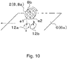
- Fig. 10 shows an example in which the principal surface 6a of the relative moving body 6 is disposed to be opposed to an outer peripheral surface of the rotor 8 while a predetermined gap is maintained therebetween.
- the principal surface 6a of the relative moving body 6 may be a flat surface or a curved surface.
- the relative moving body 6 is a rotor, and the principal surface 6a of the relative moving body 6 is an outer peripheral surface of the rotor.
- the relative moving body 6 moves in magnetic fluxes from magnetic poles 8b of a permanent magnet 8a of the rotor 8, so that an eddy current is produced on the principal surface 6a of the relative moving body 6.
- a direction of the eddy current depends on a moving direction of the relative moving body 6. While a description is given herein of an example in which the relative moving body 6 itself moves, movement of the relative moving body 6 also encompasses a case where the relative moving body 6 itself stops moving, and the rotor 8 moves. That is, movement of the relative moving body 6 refers to relative movement between the relative moving body 6 and the rotor 8.
- a gap between the principal surface 6a of the relative moving body 6 and the rotor 8 is limited to such a range that magnetic fluxes from the magnetic poles 8b of the permanent magnet 8a of the rotor 8 can reach the principal surface 6a of the relative moving body 6.
- the magnetic poles 8b of the permanent magnet 8a are magnetized in a direction toward the principal surface 6a of the relative moving body 6 opposed thereto or a direction opposite thereto. Furthermore, magnetization directions of each pair of adjacent ones of the magnetic poles 8b of the permanent magnet 8a are opposite to each other. In Fig. 10 , magnetization directions of the magnetic poles 8b of the permanent magnet 8a are indicated by arrows.
- an eddy current is produced on the principal surface 6a of the relative moving body 6.
- the rotor 8 rotates by an interaction (a repulsive force and an attractive force) between a magnetic flux produced by the eddy current and the magnetic flux from the rotor 8.
- a surface speed of a principal surface of the rotor 8 is lower than a surface speed of the principal surface 6a of the relative moving body 6 opposed thereto.
- a direction of an eddy current 12a produced on the principal surface 6a of the relative moving body 6 at a portion reached by a magnetic flux from an edge e1 of the N-pole at the front in a rotational direction is different from a direction of an eddy current 12b produced on the principal surface 6a of the relative moving body 6 at a portion reached by a magnetic flux from an edge e2 of the N-pole at the rear in the rotational direction.
- the eddy current 12b produced by the magnetic flux from the edge e2 of the N-pole at the rear in the rotational direction flows in such a direction as to produce a magnetic flux in an opposite direction to a direction of a magnetic flux from the N-pole.
- the eddy current 12a produced on the principal surface 6a of the relative moving body 6 at a portion reached by the magnetic flux from the edge e1 of the N-pole at the front in the rotational direction flows in such a direction as to produce a magnetic flux in the same direction as the direction of the magnetic flux from the N-pole.
- the eddy currents 12a and 12b both flow in such directions as to hinder a change in magnetic flux from the rotor 8 caused by rotation of the relative moving body 6.
- the direction of the magnetic flux produced by the eddy current 12a is the same as the direction of the magnetic flux from the N-pole of the rotor 8, and thus an attractive force acts therebetween.
- the direction of the magnetic flux produced by the eddy current 12b is opposite to the direction of the magnetic flux from the N-pole of the rotor 8, and thus a repulsive force acts therebetween.
- the rotor 8 rotates at a surface speed lower than the surface speed of the principal surface 6a of the relative moving body 6 opposed thereto, so as to run after a moving surface of the principal surface 6a of the relative moving body 6 opposed thereto.
- the above principle of rotation of the rotor 8 can also be described in terms of a repulsive force based on a Lorentz force.
- the direction of the eddy current 12a produced by the magnetic flux from the edge e1 of the N-pole of the rotor 8 at the front in the rotational direction is opposite to the direction of the eddy current 12b produced by the magnetic flux from the edge e2 of the N-pole of the rotor 8 at the rear in the rotational direction, and thus a current flows in a constant direction under the N-pole at all time.
- the magnetic flux change speed detecting unit 9 shown in Fig. 9 detects a frequency at which the magnetic flux producing unit 2 causes a change in magnetic flux.
- the speed estimating unit 5 determines beforehand a correspondence relationship between the frequency at which the magnetic flux producing unit 2 causes a change in magnetic flux and the moving or rotating speed of the relative moving body 6 and stores it, for example, in a table. Further, based on the frequency detected by the magnetic flux change speed detecting unit 9, the speed estimating unit 5 refers to the table (a storage unit) and thus estimates the moving or rotating speed of the relative moving body 6.
- a gap estimating unit 11 may be provided in the speed detecting device 1.
- the gap estimating unit 11 uses an unshown coil provided at a position linked with a magnetic flux of the permanent magnet 8a of the rotor 8 and, based on a current flowing through this coil and an induced voltage, estimates a gap between the relative moving body 6 and an excitation coil 2a.
- the gap estimating unit 11 estimates the gap by an impedance analysis technique. More specifically, the gap estimating unit 11 estimates the gap based on a comparison between an inductance of the above-described coil calculated based on a current flowing through the coil and an induced voltage and an inductance of a coil corresponding to a preset reference value of the gap.
- Fig. 12 is a graph showing a density of magnetic fluxes linked with the detection coil 3a.
- a horizontal axis indicates a coordinate position of the relative moving body 6 in a moving or rotating direction thereof
- a vertical axis indicates a magnetic flux density B[T].
- an amount of magnetic fluxes in a positive direction and an amount of magnetic fluxes in a negative direction, which are linked with the detection coil 3a are not equal to each other, and thus an induced voltage is induced in the detection coil 3a.
- the speed estimating unit 5 estimates the moving or rotating speed of the relative moving body 6. It is also possible that a correspondence relationship among the rotating speed of the rotor 8, the induced voltage in the detection coil 3a, the gap, and the moving or rotating speed of the relative moving body 6 is stored beforehand in a table, and by referring to the table (the storage unit), the moving or rotating speed of the relative moving body 6 is estimated.
- the rotating speed of the rotor 8, the induced voltage in the detection coil 3a, and the gap are inputted to an arithmetic formula obtained by mathematizing the above-described correspondence relationship, and thus the moving or rotating speed of the relative moving body 6 is determined.
- the moving or rotating speed of the relative moving body 6 can be estimated without performing rotation control of the rotor 8, and thus there can be obtained a more simplified configuration than those of the speed detecting devices 1 according to the first to third embodiments. Furthermore, it is also possible to take into consideration the gap between the rotor 8 and the principal surface 6a of the relative moving body 6 in estimating the moving or rotating speed of the relative moving body 6, and thus estimation accuracy can be improved.
- the concept of the above-described relative moving body 6 in each of the foregoing first to fourth embodiments includes not only a relative moving body that itself moves or rotates but also a relative moving body that moves relative to the speed detecting device 1. Therefore, in the first to fourth embodiments, in a case where the speed detecting device 1 is installed in a train or the like, a fixture such as a rail that moves relative to the train or the like is also construed as being included in the concept of the relative moving body 6.
Landscapes
- Physics & Mathematics (AREA)
- General Physics & Mathematics (AREA)
- Indicating Or Recording The Presence, Absence, Or Direction Of Movement (AREA)
- Control Of Electric Motors In General (AREA)
- Transmission And Conversion Of Sensor Element Output (AREA)
Abstract
A magnetic flux detecting unit (3) is arranged to detect an induced voltage, induced based on a magnetic flux produced by the magnetization pattern (7).
A magnetic flux frequency control unit (4) is arranged for controlling the predetermined frequency such that the induced voltage detected by the magnetic flux detecting unit (3) becomes zero, and a speed estimating unit (5) is arranged for estimating a moving or rotating speed of the relative moving body (6) in a state where the induced voltage detected by the magnetic flux detecting unit (3) is zero, based on the predetermined frequency controlled by the magnetic flux frequency control unit (4).
Description
- The present invention relates to a speed detecting device and a speed detecting method for detecting a speed without contact.
- A bicycle dynamo that produces electricity without contact is disclosed in
Patent Literature 1. In the bicycle dynamo ofPatent Literature 1, an annular permanent magnet rotates about a rotation axis extending in a direction orthogonal to a rotation axis of a wheel of a bicycle, an outer peripheral surface of the permanent magnet being disposed at a distance from a side surface of the wheel continuous with an outer peripheral surface thereof. - The permanent magnet includes a plurality of magnetic poles aligned in a circumferential direction, and magnetization directions of each pair of adjacent ones of the magnetic poles are opposite to each other. For example, when the wheel rotates in a state where an N pole of the permanent magnet is disposed to be opposed to the side surface of the wheel, an eddy current is produced on the side surface of the wheel in such a direction as to hinder a change in magnetic flux from the permanent magnet. A repulsive force and an attractive force between a magnetic flux produced by the eddy current and the magnetic flux from the permanent magnet cause the permanent magnet to rotate in a rotational direction of the wheel.
- Therefore, when a coil is wound around the permanent magnet so that a magnetic flux from the permanent magnet is linked with the coil, it is possible to obtain induced electric power from the coil.
- Although it is also possible to estimate a moving speed of the bicycle by detecting a rotating speed of the permanent magnet of
Patent Literature 1, slipping of the permanent magnet may occur, in which case it is no longer possible to accurately estimate the moving speed of the bicycle.Patent Literature 1 includes no disclosure of how to prevent slipping of the permanent magnet, and hence the technique ofPatent Literature 1 might fail to accurately estimate the moving speed of the bicycle. - In order to solve the above-described problem, an aspect of the present invention provides a speed detecting device including a magnetic flux producing unit spaced apart from a principal surface of a relative moving body and configured to produce a magnetic flux changing at a predetermined frequency so that a magnetization pattern is formed on the principal surface in accordance with movement or rotation of the relative moving body, a magnetic flux detecting unit spaced apart from the principal surface of the relative moving body and configured to detect an induced voltage induced based on a magnetic flux produced by the magnetization pattern on the principal surface, a magnetic flux frequency control unit for controlling the predetermined frequency so that the induced voltage detected by the magnetic flux detecting unit becomes zero, and a speed estimating unit for estimating a moving or rotating speed of the relative moving body in a state where the induced voltage detected by the magnetic flux detecting unit is zero, based on the predetermined frequency controlled by the magnetic flux frequency control unit.
-
-
Fig. 1 is a view showing a schematic configuration of a speed detecting device according to a first embodiment of the present invention. -
Fig. 2 is a view obtained by adding a magnetic flux change speed detecting unit to the speed detecting device shown inFig. 1 . -
Fig. 3 is a view schematically showing magnetic force lines produced from a permanent magnet of rotor. -
Fig. 4 is a graph showing a density of magnetic fluxes linked with a detection coil. -
Fig. 5 is a view showing a schematic configuration of a speed detecting device according to a second embodiment. -
Fig. 6 is a circuit diagram showing one specific example of an alternating current power source. -
Fig. 7 is a view showing a schematic configuration of a speed detecting device according to a third embodiment. -
Fig. 8A is a graph of a magnetic flux density in a case where the detection coil vertically overlaps with two magnetization patterns. -
Fig. 8B is a graph of a magnetic flux density in a case where the detection coil is positionally shifted from the two magnetization patterns in a vertical direction. -
Fig. 9 is a view showing a schematic configuration of a speed detecting device according to a fourth embodiment. -
Fig. 10 is a view showing an example in which a principal surface of a relative moving body is disposed to be opposed to an outer peripheral surface of a rotor while a predetermined gap is maintained therebetween. -
Fig. 11 is a view showing a schematic configuration of a speed detecting device obtained by adding a gap estimating unit to the configuration shown inFig. 9 . -
Fig. 12 is a graph showing a density of magnetic fluxes linked with the detection coil. - With reference to the appended drawings, the following describes an embodiment of the present disclosure. In the drawings appended hereto, for the sake of convenience of illustration and ease of understanding, a scale size, an aspect ratio, and the like are altered as appropriate from those of real things for emphasis.
- Moreover, terms, values, and so on used herein to specify a shape, a geometric condition, and an extent thereof, such as, for example, terms including "parallel," "orthogonal," and "equal" and values of a length and an angle, are not bound to a strict meaning thereof but should be interpreted as covering a range that can be expected to achieve similar functionality.
- (First Embodiment)
Fig. 1 is a view showing a schematic configuration of aspeed detecting device 1 according to a first embodiment of the present invention. Thespeed detecting device 1 shown inFIG. 1 includes a magneticflux producing unit 2, a magneticflux detecting unit 3, a magnetic fluxfrequency control unit 4, and aspeed estimating unit 5. - The magnetic
flux producing unit 2 produces a magnetic flux changing at a predetermined frequency so that amagnetization pattern 7 is formed on aprincipal surface 6a of a relative movingbody 6 as the relative movingbody 6 moves or rotates, the magneticflux producing unit 2 being disposed at a distance from theprincipal surface 6a of the relative movingbody 6. More specifically, the magneticflux producing unit 2 may be a rotor 8 including a permanent magnet 8a rotatable about a rotation axis. The permanent magnet 8a includes a plurality ofmagnetic poles 8b arranged in a circumferential direction of the rotor 8. As the rotor 8 rotates, themagnetization pattern 7 is formed by a magnetic flux from themagnetic poles 8b disposed to be opposed at a distance to theprincipal surface 6a of the relative movingbody 6. Herein, themagnetization pattern 7 refers to an area in which an intensity of magnetization is substantially the same, and the intensity of magnetization in themagnetization pattern 7 is different from that in a region outside themagnetization pattern 7. In a case where a plurality ofmagnetization patterns 7 are present on theprincipal surface 6a of the relative movingbody 6, theindividual magnetization patterns 7 may be different in intensity of magnetization. - The magnetic
flux detecting unit 3 detects an induced voltage induced based on a magnetic flux produced by themagnetization pattern 7, the magneticflux detecting unit 3 being disposed at a distance from theprincipal surface 6a of the relative movingbody 6. More specifically, the magneticflux detecting unit 3 includes adetection coil 3a having a diameter corresponding to an interval between themagnetic poles 8b of the permanent magnet 8a in the magneticflux producing unit 2. Thedetection coil 3a may have any number of turns. The magneticflux detecting unit 3 is not necessarily required to use thedetection coil 3a and may use any other member that detects a magnetic flux from themagnetization pattern 7 formed on theprincipal surface 6a of the relative moving body 6 (for example, a Hall element or the like). The following describes an example in which thedetection coil 3a is used as the magneticflux detecting unit 3. - The magnetic flux
frequency control unit 4 controls a frequency at which the magneticflux producing unit 2 causes a change in magnetic flux so that an induced voltage detected by the magneticflux detecting unit 3 becomes zero. More specifically, the magnetic fluxfrequency control unit 4 controls a moving or rotating speed of the relative movingbody 6 to be equal to a rotating speed of the rotor 8 so that the induced voltage detected by the magneticflux detecting unit 3 becomes zero. During a time period in which the relative movingbody 6 is moving or rotating, the magnetic fluxfrequency control unit 4 may continuously control the rotating speed of the rotor 8 so that the induced voltage detected by the magneticflux detecting unit 3 becomes zero. - The
speed estimating unit 5 estimates the moving or rotating speed of the relative movingbody 6 in a state where the induced voltage detected by the magneticflux detecting unit 3 is zero, based on the frequency controlled by the magnetic fluxfrequency control unit 4. Based on a frequency produced in the magneticflux producing unit 2 when the induced voltage detected by the magneticflux detecting unit 3 becomes zero, thespeed estimating unit 5 can estimate the moving or rotating speed of the relative movingbody 6 without detecting the rotating speed of the rotor 8. - The relative moving
body 6 is a magnetic body having theprincipal surface 6a on which themagnetization pattern 7 can be formed by the magneticflux producing unit 2. -
Fig. 2 is a view obtained by adding a magnetic flux changespeed detecting unit 9 to thespeed detecting device 1 shown inFig. 1 . The magnetic flux changespeed detecting unit 9 detects a frequency at which the magneticflux producing unit 2 causes a change in magnetic flux. In a case where the magneticflux producing unit 2 is the rotor 8, using an unshown Hall element or the like, the magnetic flux changespeed detecting unit 9 detects the rotating speed of the rotor 8. In this case, thespeed estimating unit 5 estimates the moving or rotating speed of the relative movingbody 6 in a state where the induced voltage detected by the magneticflux detecting unit 3 is zero, based on the frequency detected by the magnetic flux change speed detecting unit 9 (more specifically, the rotating speed of the rotor 8). The moving or rotating speed of the relative movingbody 6 can be estimated using Formula (1) below.
- The rotor 8 should ideally rotate at a rotating speed equal to the moving or rotating speed of the relative moving
body 6. In reality, however, due to friction or the like, the rotating speed of the rotor 8 is lower than the moving or rotating speed of the relative movingbody 6. Herein, a situation in which the rotating speed of the rotor 8 is slower than the moving or rotating speed of the relative movingbody 6 is referred to as slipping of the rotor 8. -
Fig. 3 is a view schematically showing magnetic force lines produced from the permanent magnet 8a of the rotor 8. The permanent magnet 8a shown inFig. 3 has four magnetic poles (two N poles and two S poles) arranged in the circumferential direction. The permanent magnet 8a may have any number of magnetic poles. The magnetic force lines emanating from each of the N poles pass over theprincipal surface 6a of the relative movingbody 6 and then travel toward one of the S poles adjacent thereto. By these magnetic poles, an N pole-magnetizedmagnetization pattern 7 and an S pole-magnetizedmagnetization pattern 7 are alternately formed in proximity to each other on the surface of the relative movingbody 6 along a moving direction of the relative movingbody 6. From themagnetization patterns 7, the magnetic force lines are emanating in directions corresponding to polarities thereof. The magnetic force lines from each of themagnetization patterns 7 are provided in a path along which the magnetic force lines pass through the air, travel inside the relative movingbody 6, and return to the each of themagnetization patterns 7. - Each of the
magnetization patterns 7 has a size depending on the moving or rotating speed of the relative movingbody 6 and the rotating speed of the rotor 8. When the moving or rotating speed of the relative movingbody 6 is equal to the rotating speed of the rotor 8, regardless of the moving or rotating speed of the relative movingbody 6, themagnetization patterns 7 have a constant size. - For example, in a case where the rotating speed of the rotor 8 is equal to the moving speed of the relative moving
body 6, thedetection coil 3a has a diameter defined by a combined region of the twoadjacent magnetization patterns 7 having the opposite polarities. Accordingly, while a substantially equal amount of magnetic force lines from each of the twomagnetization patterns 7 are linked with thedetection coil 3a, since respective directions of the magnetic force lines from the twomagnetization patterns 7 are opposite to each other, magnetic fluxes linked with thedetection coil 3a cancel out each other and thus become substantially zero. Therefore, no induced voltage is produced in thedetection coil 3a, and thus no induced current flows therethrough. - The
detection coil 3a may have any diameter defined by a combined size of even number ofmagnetization patterns 7. For example, in a case where thedetection coil 3a has a diameter defined by a combined size of 2n (n is an integer of 1 or more)magnetization patterns 7, n magnetic fluxes in a positive direction and n magnetic fluxes in a negative direction, which are linked with thedetection coil 3a, cancel out each other, and thus an induced voltage in thedetection coil 3a becomes zero. For the sake of simplified explanation, the following describes an example in which thedetection coil 3a has a diameter defined by a combined size of twomagnetization patterns 7. -
Fig. 4 is a graph showing a density of magnetic fluxes linked with thedetection coil 3a. In the graph ofFig. 4 , a horizontal axis indicates a coordinate position of the relative movingbody 6 in a moving or rotating direction thereof, and a vertical axis indicates a magnetic flux density B[T]. InFig. 4 , a hatched region represents a density of magnetic fluxes linked with thedetection coil 3a. The density of magnetic fluxes linked with thedetection coil 3a in a positive direction has an area equal to that in a negative direction, and these magnetic fluxes in the positive and negative directions cancel out each other, so that no induced voltage is produced in thedetection coil 3a, and thus no induced current flows therethrough. - In this embodiment, the magnetic flux
frequency control unit 4 controls a frequency of a magnetic flux, thus controlling the rotating speed of the rotor 8 to be equal to the moving or rotating speed of the relative movingbody 6. Accordingly, themagnetization patterns 7 are controlled to have a constant size. Therefore, with thedetection coil 3a preset to have a diameter defined by a combined size of the twomagnetization patterns 7, when a current flowing through thedetection coil 3a is zero, i.e. when an induced voltage induced in thedetection coil 3a is zero, it can be determined that the rotating speed of the rotor 8 is equal to the moving or rotating speed of the relative movingbody 6. - The magnetic flux
frequency control unit 4 includes, for example, an unshown motor for driving a rotary shaft of the rotor 8 to rotate. The magnetic fluxfrequency control unit 4 adjusts a rotational drive force of the motor and thus controls the rotating speed of the rotor 8. More specifically, the magnetic fluxfrequency control unit 4 controls the magneticflux detecting unit 3 to detect an induced voltage induced in thedetection coil 3a, and based on a result of the detection, controls the rotating speed of the rotor 8 so that the induced voltage becomes zero. - The
speed estimating unit 5 shown inFig. 1 estimates the moving or rotating speed of the relative movingbody 6 in a state where an induced voltage in thedetection coil 3a is zero, based on a frequency of a magnetic flux controlled by the magnetic fluxfrequency control unit 4. On the other hand, thespeed estimating unit 5 shown inFig. 2 estimates the moving or rotating speed of the relative movingbody 6 in a state where an induced voltage in thedetection coil 3a is zero, based on the rotating speed of the rotor 8 detected by the magnetic flux changespeed detecting unit 9. When an induced voltage in thedetection coil 3a is zero, the rotating speed of the rotor 8 can be regarded as being equal to the moving or rotating speed of the relative movingbody 6, and thus thespeed estimating unit 5 can easily estimate the moving or rotating speed of the relative movingbody 6. - As described above, in the first embodiment, even in a case where a distance between the relative moving
body 6 and the magneticflux producing unit 2 changes, the moving or rotating speed of the relative movingbody 6 can be estimated based on a frequency produced by the magneticflux producing unit 2 when an induced voltage detected by the magneticflux detecting unit 3 becomes zero. This embodiment addresses the following circumstances. That is, in a case where the rotor 8 is disposed to be opposed at a distance to theprincipal surface 6a of the relative movingbody 6, and the moving or rotating speed of the relative movingbody 6 is estimated from the rotating speed of the rotor 8 configured to rotate as the relative movingbody 6 moves or rotates, due to a speed difference (slipping) between the rotor 8 and the relative movingbody 6, the moving or rotating speed of the relative movingbody 6 cannot be accurately estimated. In this embodiment, in order to detect a state where slipping of the rotor 8 is zero, the rotor 8 is purposely driven to rotate by the magnetic fluxfrequency control unit 4 so that an induced voltage in thedetection coil 3a becomes zero. When an induced voltage in thedetection coil 3a has become zero, the rotating speed of the rotor 8 can be regarded as being equal to the moving or rotating speed of the relative movingbody 6, and thus the moving or rotating speed of the relative movingbody 6 can be easily estimated from the rotating speed of the rotor 8. - Furthermore, this embodiment actively uses the
magnetization pattern 7 formed on theprincipal surface 6a of the relative movingbody 6 by a magnetic force of the permanent magnet 8a of the rotor 8. The rotating speed of the rotor 8 is controlled to be equal to the moving or rotating speed of the relative movingbody 6 so that themagnetization patterns 7 on theprincipal surface 6a of the relative movingbody 6 have an equal size. Further, thedetection coil 3a has a diameter defined by a combined size of the twomagnetization patterns 7, and thus an amount of magnetic fluxes in the positive direction from one of themagnetization patterns 7 and an amount of magnetic fluxes in the negative direction from theother magnetization pattern 7, which are linked with thedetection coil 3a when the rotating speed of the rotor 8 is equal to the moving or rotating speed of the relative movingbody 6, can be cancelled out. Therefore, without being affected by a gap variation, the moving or rotating speed of the relative movingbody 6 can be accurately estimated using a simple configuration. - (Second Embodiment) A second embodiment differs from the first embodiment in configuration of the magnetic
flux producing unit 2. -
Fig. 5 is a view showing a schematic configuration of aspeed detecting device 1 according to the second embodiment. Similarly to thespeed detecting device 1 shown inFig. 1 , thespeed detecting device 1 shown inFig. 5 includes a magneticflux producing unit 2, a magneticflux detecting unit 3, a magnetic fluxfrequency control unit 4, and aspeed estimating unit 5. - The magnetic
flux producing unit 2 shown inFig. 5 includes anexcitation coil 2a and an alternatingcurrent power source 2b. Theexcitation coil 2a produces a magnetic flux changing a polarity of amagnetization pattern 7 at a predetermined frequency, themagnetization pattern 7 being formed on aprincipal surface 6a of a relative movingbody 6. The alternatingcurrent power source 2b passes an alternating current through theexcitation coil 2a. Based on a control signal from the magnetic fluxfrequency control unit 4, the alternatingcurrent power source 2b switches a frequency of the alternating current. Thus, a direction of the current flowing through theexcitation coil 2a changes to cause a direction of a magnetic flux produced from theexcitation coil 2a to be inverted. The magnetic flux produced from theexcitation coil 2a passes over theprincipal surface 6a of the relative movingbody 6. At this time, on theprincipal surface 6a of the relative movingbody 6, there is formed themagnetization pattern 7 having a polarity corresponding to the direction of the current flowing through theexcitation coil 2a. -
Fig. 6 is a circuit diagram showing a specific example of the alternatingcurrent power source 2b. As shown inFig. 6 , the magneticflux producing unit 2 includes anoscillation circuit 2c and anammeter 2d. Theoscillation circuit 2c includes two capacitors C1 and C2 and two switches SW1 and SW2. The two capacitors C1 and C2 are connected in series between two terminals to which a direct-current voltage Udc is applied. The two switches SW1 and SW2 are also connected in series between the two terminals to which the direct-current voltage Udc is applied. One end of theexcitation coil 2a is connected to a connection node between the two switches SW1 and SW2 via theammeter 2d, and the other end of theexcitation coil 2a is connected to a connection node between the two capacitors C1 and C2. A switching frequency of the switches SW1 and SW2 can be controlled based on a control signal from the magnetic fluxfrequency control unit 4. - The magnetic flux
frequency control unit 4 controls a frequency at which a direction of the current passed through theexcitation coil 2a is switched so that an induced voltage detected by adetection coil 3a becomes zero. - The polarity of the
magnetization pattern 7 on theprincipal surface 6a of the relative movingbody 6 changes with the direction of the current flowing through theexcitation coil 2a, and thus using the frequency at which the direction of the current flowing through theexcitation coil 2a is switched, a size of themagnetization pattern 7 on the relative movingbody 6 can be adjusted. - In this embodiment, a diameter of the
detection coil 3a is preset to a given length. The magnetic fluxfrequency control unit 4 causes the frequency of the current passed through theexcitation coil 2a to vary so as to detect a frequency at which the induced voltage in thedetection coil 3a becomes zero, and based on the frequency thus detected, calculates (estimates) a moving or rotating speed of the relative movingbody 6 using Formula (2) below.
- More specifically, the magnetic flux
frequency control unit 4 gradually increases the frequency of the current passed through theexcitation coil 2a from a predetermined low frequency value as an initial frequency value and selects a frequency value at which the induced voltage in thedetection coil 3a becomes zero for the first time. - As described above, in the second embodiment, the frequency at which the direction of the current flowing through the
excitation coil 2a is switched is controlled so that the induced voltage in thedetection coil 3a becomes zero. Using a current switching frequency of theexcitation coil 2a at which the induced voltage in thedetection coil 3a becomes zero, the moving or rotating speed of the relative movingbody 6 can be simply and accurately estimated. - In the first embodiment, the rotor 8 is used as the magnetic
flux producing unit 2, and thus a mechanical mechanism for rotating the rotor 8 is required, whereas in the second embodiment, theexcitation coil 2a is used as the magneticflux producing unit 2, and thus it is only required to switch a direction of a current flowing through theexcitation coil 2a, thus eliminating the need for a mechanical mechanism and providing a configuration more resistant to breakage and further improved in maintainability. - (Third Embodiment) A third embodiment uses a voice coil unit as the magnetic
flux producing unit 2. -
Fig. 7 is a view showing a schematic configuration of aspeed detecting device 1 according to the third embodiment. Similarly to thespeed detecting device 1 shown inFig. 1 , thespeed detecting device 1 shown inFig. 7 includes a magneticflux producing unit 2, a magneticflux detecting unit 3, a magnetic fluxfrequency control unit 4, and aspeed estimating unit 5. - The magnetic
flux producing unit 2 shown inFig. 7 includes avoice coil unit 21. Thevoice coil unit 21 includes apermanent magnet 21a, avoice coil 21b, and aspring member 21c. Thepermanent magnet 21a has two magnetic poles disposed along a direction normal to aprincipal surface 6a of a relative movingbody 6. Thevoice coil 21b is wound on thepermanent magnet 21a. Thespring member 21c is connected to one end side of thepermanent magnet 21a. An alternating current from apower source 21d is passed through thevoice coil 21b, and thus a force is applied to thepermanent magnet 21a to cause thespring member 21c to expand or contract, so that there occurs a change in gap between the magnetic pole of thepermanent magnet 21a on the other end side and theprincipal surface 6a of the relative movingbody 6. - When a current is passed through the
voice coil 21b, a force is applied to thepermanent magnet 21 a by a Lorentz force acting between thevoice coil 21b and a magnetic field of thepermanent magnet 21a. A direction of the Lorentz force changes with a direction of the current passed through thevoice coil 21b. Thus, thepermanent magnet 21a vibrates in accordance with a current switching frequency of thevoice coil 21b, so that there occurs a change in gap between a distal end portion of the magnetic pole of thepermanent magnet 21a on the other end side and theprincipal surface 6a of the relative movingbody 6. - The smaller the gap, the higher an intensity of magnetization of a
magnetization pattern 7 on theprincipal surface 6a of the relative movingbody 6, and the larger the gap, the lower the intensity of magnetization of themagnetization pattern 7 on theprincipal surface 6a of the relative movingbody 6. Therefore, on theprincipal surface 6a of the relative movingbody 6, two types ofmagnetization patterns 7 different in intensity of magnetization are alternately formed in synchronization of vibrations of thepermanent magnet 21a. - While in the first and second embodiments, two types of
magnetization patterns 7 having different polarities are alternately formed on theprincipal surface 6a of the relative movingbody 6, in this embodiment, two types ofmagnetization patterns 7 different in intensity of magnetization are formed thereon. - A
detection coil 3a has a diameter defined by, for example, a combined size of twoadjacent magnetization patterns 7. Therefore, magnetic fluxes from the twoadjacent magnetization patterns 7 are linked with thedetection coil 3a. These magnetic fluxes are the same in direction and thus, unlike in the first and second embodiments, the magnetic fluxes are not cancelled out. -
Fig. 8A andFig. 8B are each a graph of a density of magnetic fluxes linked with thedetection coil 3a. In each of these graphs, a horizontal axis indicates a coordinate position of the relative movingbody 6 in a moving or rotating direction thereof, and a vertical axis indicates a magnetic flux density B[T]. In a case where one cycle of high and low intensity values of magnetization of themagnetization patterns 7 is included across thedetection coil 3a, a density of magnetic fluxes linked with thedetection coil 3a is as shown in the graph ofFig. 8A . In this case, an amount of magnetic fluxes lined with thedetection coil 3a is constant at all time, thus causing no change in magnetic flux, so that no induced voltage is produced in thedetection coil 3a. In a case where one cycle of high and low intensity values of magnetization of themagnetization patterns 7 is not included across thedetection coil 3a, a density of magnetic fluxes linked with thedetection coil 3a is as shown in the graph ofFig. 8B . In this case, an amount of magnetic fluxes lined with thedetection coil 3a changes with time, so that an induced voltage is produced in thedetection coil 3a. - Therefore, the magnetic flux
frequency control unit 4 controls the current switching frequency of thevoice coil 21b so that the induced voltage detected by thedetection coil 3a becomes zero and estimates a moving or rotating speed of the relative movingbody 6, based on the current switching frequency of thevoice coil 21b at the time when the induced voltage is zero and a diameter of thedetection coil 3a. - As described above, in the third embodiment, the current switching frequency of the
voice coil 21b is controlled so that the induced voltage detected by thedetection coil 3a becomes zero, and thus the moving or rotating speed of the relative movingbody 6 can be estimated based on the current switching frequency of thevoice coil 21 b at the time when the induced voltage is zero and the diameter of thedetection coil 3a. In the third embodiment, thepermanent magnet 21a having a strong magnetic force is used, and thus even when a current passed through thevoice coil 21b is small, themagnetization patterns 7 can be formed on theprincipal surface 6a of the relative movingbody 6, so that power consumption may be reduced more than in the first and second embodiments. - (Fourth Embodiment) While in the first and second embodiments, the rotating speed of the rotor 8 or the current switching frequency of the
excitation coil 2a is controlled in accordance with the moving or rotating speed of the relative movingbody 6, a configuration including no such control is also possible. -
Fig. 9 is a view showing a schematic configuration of aspeed detecting device 1 according to a fourth embodiment. Thespeed detecting device 1 shown inFig. 9 includes a magneticflux producing unit 2, a magneticflux detecting unit 3, a magnetic flux changespeed detecting unit 9, and aspeed estimating unit 5. The magneticflux producing unit 2 and the magneticflux detecting unit 3 are configured similarly to those inFig. 5 . - The magnetic
flux producing unit 2 is, for example, a rotor 8 rotatable about a rotation axis, and the rotor 8 of this embodiment is caused to rotate by a magnetic flux produced by an eddy current, the eddy current being produced on aprincipal surface 6a of a relative movingbody 6 based on a moving or rotating speed of the relative movingbody 6. Thespeed detecting device 1 shown inFig. 9 does not include the magnetic fluxfrequency control unit 4 shown inFig. 1 , and thus the rotor 8 performs a passive rotary operation in which the rotor 8 rotates at a rotating speed based on the moving or rotating speed of the relative movingbody 6. Thus, the rotating speed of the rotor 8 is equal to or less than the moving or rotating speed of the relative movingbody 6. That is, it is prerequisite to rotation of the rotor 8 that there is a difference between the rotating speed of the rotor 8 and the moving or rotating speed of the relative movingbody 6. -
Fig. 10 shows an example in which theprincipal surface 6a of the relative movingbody 6 is disposed to be opposed to an outer peripheral surface of the rotor 8 while a predetermined gap is maintained therebetween. Theprincipal surface 6a of the relative movingbody 6 may be a flat surface or a curved surface. In a typical example, the relative movingbody 6 is a rotor, and theprincipal surface 6a of the relative movingbody 6 is an outer peripheral surface of the rotor. - The relative moving
body 6 moves in magnetic fluxes frommagnetic poles 8b of a permanent magnet 8a of the rotor 8, so that an eddy current is produced on theprincipal surface 6a of the relative movingbody 6. A direction of the eddy current depends on a moving direction of the relative movingbody 6. While a description is given herein of an example in which the relative movingbody 6 itself moves, movement of the relative movingbody 6 also encompasses a case where the relative movingbody 6 itself stops moving, and the rotor 8 moves. That is, movement of the relative movingbody 6 refers to relative movement between the relative movingbody 6 and the rotor 8. A gap between theprincipal surface 6a of the relative movingbody 6 and the rotor 8 is limited to such a range that magnetic fluxes from themagnetic poles 8b of the permanent magnet 8a of the rotor 8 can reach theprincipal surface 6a of the relative movingbody 6. - The
magnetic poles 8b of the permanent magnet 8a are magnetized in a direction toward theprincipal surface 6a of the relative movingbody 6 opposed thereto or a direction opposite thereto. Furthermore, magnetization directions of each pair of adjacent ones of themagnetic poles 8b of the permanent magnet 8a are opposite to each other. InFig. 10 , magnetization directions of themagnetic poles 8b of the permanent magnet 8a are indicated by arrows. - As shown in
Fig. 10 , based on a polarity of each of themagnetic poles 8b of the permanent magnet 8a disposed to be opposed to theprincipal surface 6a of the relative movingbody 6, an eddy current is produced on theprincipal surface 6a of the relative movingbody 6. When the relative movingbody 6 moves or rotates, an eddy current is produced on theprincipal surface 6a of the relative movingbody 6 in such a direction as to hinder a change in magnetic flux from the rotor 8. The rotor 8 rotates by an interaction (a repulsive force and an attractive force) between a magnetic flux produced by the eddy current and the magnetic flux from the rotor 8. A surface speed of a principal surface of the rotor 8 is lower than a surface speed of theprincipal surface 6a of the relative movingbody 6 opposed thereto. - For example, when an N-pole of the rotor 8 is disposed to be opposed to the
principal surface 6a of the relative movingbody 6, a direction of aneddy current 12a produced on theprincipal surface 6a of the relative movingbody 6 at a portion reached by a magnetic flux from an edge e1 of the N-pole at the front in a rotational direction is different from a direction of aneddy current 12b produced on theprincipal surface 6a of the relative movingbody 6 at a portion reached by a magnetic flux from an edge e2 of the N-pole at the rear in the rotational direction. The eddy current 12b produced by the magnetic flux from the edge e2 of the N-pole at the rear in the rotational direction flows in such a direction as to produce a magnetic flux in an opposite direction to a direction of a magnetic flux from the N-pole. On the other hand, theeddy current 12a produced on theprincipal surface 6a of the relative movingbody 6 at a portion reached by the magnetic flux from the edge e1 of the N-pole at the front in the rotational direction flows in such a direction as to produce a magnetic flux in the same direction as the direction of the magnetic flux from the N-pole. Theeddy currents body 6. - As described above, on the edge e1 side of the N-pole of the rotor 8 at the front in the rotational direction, the direction of the magnetic flux produced by the
eddy current 12a is the same as the direction of the magnetic flux from the N-pole of the rotor 8, and thus an attractive force acts therebetween. On the other hand, on the edge e2 side of the N-pole of the rotor 8 at the rear in the rotational direction, the direction of the magnetic flux produced by the eddy current 12b is opposite to the direction of the magnetic flux from the N-pole of the rotor 8, and thus a repulsive force acts therebetween. When the surface speed of the outer peripheral surface of the rotor 8 is lower than the surface speed of theprincipal surface 6a of the relative movingbody 6 opposed thereto, the above-described relationship between the rotor 8 and theeddy currents principal surface 6a of the relative movingbody 6 opposed thereto, so as to run after a moving surface of theprincipal surface 6a of the relative movingbody 6 opposed thereto. - The above principle of rotation of the rotor 8 can also be described in terms of a repulsive force based on a Lorentz force. As described above, the direction of the
eddy current 12a produced by the magnetic flux from the edge e1 of the N-pole of the rotor 8 at the front in the rotational direction is opposite to the direction of the eddy current 12b produced by the magnetic flux from the edge e2 of the N-pole of the rotor 8 at the rear in the rotational direction, and thus a current flows in a constant direction under the N-pole at all time. When the relative movingbody 6 rotates in a direction indicated by an arrow shown inFig. 10 , currents produced by theeddy currents body 6. Therefore, the rotor 8 subjected to the magnetic fluxes produced by theeddy currents body 6. As described above, the rotor 8 and the relative movingbody 6 move in the same direction at the opposed surfaces thereof. - The magnetic flux change
speed detecting unit 9 shown inFig. 9 detects a frequency at which the magneticflux producing unit 2 causes a change in magnetic flux.
Thespeed estimating unit 5 determines beforehand a correspondence relationship between the frequency at which the magneticflux producing unit 2 causes a change in magnetic flux and the moving or rotating speed of the relative movingbody 6 and stores it, for example, in a table. Further, based on the frequency detected by the magnetic flux changespeed detecting unit 9, thespeed estimating unit 5 refers to the table (a storage unit) and thus estimates the moving or rotating speed of the relative movingbody 6. It is also possible that, instead of using a table, a function formula representing the above-described correspondence relationship is prepared beforehand, and the frequency detected by the magnetic flux changespeed detecting unit 9 is substituted into this function formula, and thus the moving or rotating speed of the relative movingbody 6 is estimated. - Meanwhile, the rotating speed of the rotor 8 changes with a distance (a gap) between the
principal surface 6a of the relative movingbody 6 and the outer peripheral surface of the rotor 8. Thus, as shown inFig. 11 , agap estimating unit 11 may be provided in thespeed detecting device 1. - For example, the
gap estimating unit 11 uses an unshown coil provided at a position linked with a magnetic flux of the permanent magnet 8a of the rotor 8 and, based on a current flowing through this coil and an induced voltage, estimates a gap between the relative movingbody 6 and anexcitation coil 2a. - The
gap estimating unit 11 estimates the gap by an impedance analysis technique. More specifically, thegap estimating unit 11 estimates the gap based on a comparison between an inductance of the above-described coil calculated based on a current flowing through the coil and an induced voltage and an inductance of a coil corresponding to a preset reference value of the gap. -
Fig. 12 is a graph showing a density of magnetic fluxes linked with thedetection coil 3a. In the graph ofFig. 12 , a horizontal axis indicates a coordinate position of the relative movingbody 6 in a moving or rotating direction thereof, and a vertical axis indicates a magnetic flux density B[T]. Unlike in the graph ofFig. 4 , in the graph ofFig. 12 , an amount of magnetic fluxes in a positive direction and an amount of magnetic fluxes in a negative direction, which are linked with thedetection coil 3a, are not equal to each other, and thus an induced voltage is induced in thedetection coil 3a. - In a case where the gap is taken into consideration, based on the rotating speed of the rotor 8 detected by the magnetic flux change
speed detecting unit 9, the induced voltage in thedetection coil 3a detected by the magneticflux detecting unit 3, and the gap estimated by thegap estimating unit 11, thespeed estimating unit 5 estimates the moving or rotating speed of the relative movingbody 6. It is also possible that a correspondence relationship among the rotating speed of the rotor 8, the induced voltage in thedetection coil 3a, the gap, and the moving or rotating speed of the relative movingbody 6 is stored beforehand in a table, and by referring to the table (the storage unit), the moving or rotating speed of the relative movingbody 6 is estimated. Alternatively, it is also possible that the rotating speed of the rotor 8, the induced voltage in thedetection coil 3a, and the gap are inputted to an arithmetic formula obtained by mathematizing the above-described correspondence relationship, and thus the moving or rotating speed of the relative movingbody 6 is determined. - As described above, in the fourth embodiment, the moving or rotating speed of the relative moving
body 6 can be estimated without performing rotation control of the rotor 8, and thus there can be obtained a more simplified configuration than those of thespeed detecting devices 1 according to the first to third embodiments. Furthermore, it is also possible to take into consideration the gap between the rotor 8 and theprincipal surface 6a of the relative movingbody 6 in estimating the moving or rotating speed of the relative movingbody 6, and thus estimation accuracy can be improved. - The concept of the above-described relative
moving body 6 in each of the foregoing first to fourth embodiments includes not only a relative moving body that itself moves or rotates but also a relative moving body that moves relative to thespeed detecting device 1. Therefore, in the first to fourth embodiments, in a case where thespeed detecting device 1 is installed in a train or the like, a fixture such as a rail that moves relative to the train or the like is also construed as being included in the concept of the relative movingbody 6. - Aspects of the present invention are not limited to the foregoing individual embodiments and embrace various modifications conceivable by those skilled in the art. Advantageous effects of the present invention are also not limited to those described above. That is, various additions, changes, and partial deletions are possible in a range not departing from the conceptual ideas and spirit of the present invention derived from contents defined in the claims and equivalents thereof.
Claims (16)
- A speed detecting device (1), comprising:a magnetic flux producing unit (2) spaced apart from a principal surface (6a) of a relative moving body (6) and configured to produce a magnetic flux changing at a predetermined frequency so that a magnetization pattern (7) is formed on the principal surface (6a) in accordance with movement or rotation of the relative moving body (6);a magnetic flux detecting unit (3) spaced apart from the principal surface (6a) of the relative moving body (6) and configured to detect an induced voltage induced based on a magnetic flux produced by the magnetization pattern (7) on the principal surface (6a);a magnetic flux frequency control unit (4) for controlling the predetermined frequency so that the induced voltage detected by the magnetic flux detecting unit (3) becomes zero; anda speed estimating unit (5) for estimating a moving or rotating speed of the relative moving body (6) in a state where the induced voltage detected by the magnetic flux detecting unit (3) is zero, based on the predetermined frequency controlled by the magnetic flux frequency control unit (4).
- The speed detecting device (1) according to claim 1, wherein the magnetic flux producing unit (2) includes a rotor (8) having a permanent magnet (8a) rotatable about a rotation axis,
wherein the permanent magnet (8a) includes a plurality of magnetic poles (8b) arranged in a circumferential direction of the rotor (8),
wherein the magnetization pattern (7) is formed in accordance with rotation of the rotor (8) by a magnetic flux from the magnetic poles (8b) spaced apart from and opposed to the principal surface (6a) of the relative moving body (6),
wherein the magnetic flux detecting unit (3) includes a detection coil (3a) having a diameter corresponding to an interval between a plurality of magnetization patterns (7) formed on the principal surface (6a) of the relative moving body (6), and
wherein the magnetic flux frequency control unit (4) controls the moving or rotating speed of the relative moving body (6) to be equal to a rotating speed of the rotor (8) so that the induced voltage detected by the detection coil (3a) becomes zero. - The speed detecting device (1) according to claim 2, wherein during a time period in which the relative moving body (6) is moving or rotating, the magnetic flux frequency control unit (4) continuously controls the rotating speed of the rotor (8) so that the induced voltage detected by the detection coil (3a) becomes zero.
- The speed detecting device (1) according to any one of claims 1 to 3, further comprising:a magnetic flux change speed detecting unit (9) for detecting the predetermined frequency at which the magnetic flux producing unit (2) causes a change in magnetic flux,wherein the speed estimating unit (5) estimates the moving or rotating speed of the relative moving body (6) in a state where the induced voltage detected by the magnetic flux detecting unit (3) is zero, based on the predetermined frequency detected by the magnetic flux change speed detecting unit (9).
- A speed detecting device (1), comprising:a magnetic flux producing unit (2) spaced apart from a principal surface (6a) of a relative moving body (6) and configured to produce a magnetic flux changing at a predetermined frequency so that a magnetization pattern (7) is formed on the principal surface (6a) in accordance with movement or rotation of the relative moving body (6);a magnetic flux detecting unit (3) spaced apart from the principal surface (6a) of the relative moving body (6) and configured to detect an induced voltage induced based on a magnetic flux produced by the magnetization pattern (7) on the principal surface (6a);a magnetic flux change speed detecting unit (9) for detecting the predetermined frequency at which the magnetic flux producing unit (2) causes a change in magnetic flux; anda speed estimating unit (5) for estimating a moving or rotating speed of the relative moving body (6), based on the predetermined frequency detected by the magnetic flux change speed detecting unit (9) and the induced voltage detected by the magnetic flux detecting unit (3).
- The speed detecting device (1) according to claim 5, further comprising:a gap estimating unit (11) for estimating a gap between the magnetic flux producing unit (2) and the principal surface (6a) of the relative moving body (6),wherein the speed estimating unit (5) estimates the moving or rotating speed of the relative moving body (6), based on the gap estimated, the predetermined frequency detected by the magnetic flux change speed detecting unit (9), and the induced voltage detected by the magnetic flux detecting unit (3).
- The speed detecting device (1) according to claim 6, wherein the magnetic flux producing unit (2) includes a rotor (8) having a permanent magnet (8a) rotatable about a rotation axis,
wherein the permanent magnet (8a) includes a plurality of magnetic poles (8b) arranged in a circumferential direction of the rotor (8),
wherein the magnetization pattern (7) is formed in accordance with rotation of the rotor (8) by a magnetic flux from the magnetic poles (8b) spaced apart from and opposed to the principal surface (6a) of the relative moving body (6),
wherein the gap estimating unit (11) estimates a gap between an outer peripheral surface of the rotor (8) and the principal surface (6a) of the relative moving body (6),
wherein the magnetic flux change speed detecting unit (9) detects a rotating speed of the rotor (8),
wherein the magnetic flux detecting unit (3) includes a detection coil (3a) having a predetermined diameter, and
wherein the speed estimating unit (5) estimates the moving or rotating speed of the relative moving body (6), based on the gap estimated, the rotating speed of the rotor (8), and the induced voltage produced in the detection coil (3a). - The speed detecting device (1) according to claim 7, further comprising:a storage unit for storing correlation data on a correlation among the rotating speed of the rotor (8), the induced voltage, and the moving or rotating speed of the relative moving body (6),wherein, based on the gap estimated by the gap estimating unit (11), the rotating speed of the rotor (8) detected by the magnetic flux change speed detecting unit (9), and the induced voltage detected by the detection coil (3a), the speed estimating unit (5) refers to the correlation data and thus estimates a corresponding value of the moving or rotating speed of the relative moving body (6).
- The speed detecting device (1) according to claim 7, wherein the speed estimating unit (5) estimates the moving or rotating speed of the relative moving body (6), based on a result of an arithmetic process in which the gap estimated by the gap estimating unit (11), the rotating speed of the rotor (8) detected by the magnetic flux change speed detecting unit (9), and the induced voltage detected by the detection coil (3a) are substituted into a predetermined arithmetic formula.
- The speed detecting device (1) according to claim 1, wherein the magnetic flux producing unit (2) includes an excitation coil (2a) for producing a magnetic flux changing a polarity of the magnetization pattern (7) at the predetermined frequency, the magnetization pattern (7) being formed on the principal surface (6a) of the relative moving body (6),
wherein the magnetic flux detecting unit (3) includes a detection coil (3a) having a predetermined diameter,
wherein the magnetic flux frequency control unit (4) controls the predetermined frequency so that the induced voltage detected by the detection coil (3a) becomes zero, and
wherein the speed estimating unit (5) estimates the moving or rotating speed of the relative moving body (6) in a state where the induced voltage detected by the detection coil (3a) is zero, based on the predetermined frequency controlled by the magnetic flux frequency control unit (4) so that the induced voltage detected by the detection coil (3a) becomes zero and the diameter of the detection coil (3a). - The speed detecting device (1) according to claim 10, wherein the magnetic flux frequency control unit (4) gradually increases the predetermined frequency from a predetermined initial frequency value lower than the moving or rotating speed of the relative moving body (6) and causes a change in magnetic flux of the excitation coil (2a) at a frequency value at which the induced voltage detected by the detection coil (3a) becomes zero for the first time, and
wherein the speed estimating unit (5) estimates the moving or rotating speed of the relative moving body (6) by obtaining a product of the diameter of the detection coil (3a) and the frequency value of the predetermined frequency having being controlled by the magnetic flux frequency control unit (4). - The speed detecting device (1) according to claim 1, wherein the magnetic flux producing unit (2) includes an excitation coil (2a) for producing a magnetic flux changing an intensity of magnetization of the magnetization pattern (7) at the predetermined frequency, the magnetization pattern (7) being formed on the principal surface (6a) of the relative moving body (6),
wherein the magnetic flux detecting unit (3) includes a detection coil (3a) having a predetermined diameter,
wherein the magnetic flux frequency control unit (4) controls the predetermined frequency so that the induced voltage detected by the detection coil (3a) becomes zero, and
wherein the speed estimating unit (5) estimates the moving or rotating speed of the relative moving body (6) in a state where the induced voltage detected by the detection coil (3a) is zero, based on the predetermined frequency controlled by the magnetic flux frequency control unit (4) and the diameter of the detection coil (3a). - The speed detecting device (1) according to claim 12, wherein the magnetic flux producing unit (2) includes:a permanent magnet (8a) spaced apart from and opposed to the principal surface (6a) of the relative moving body (6); anda voice coil (21b) for causing a change in gap between the principal surface (6a) of the relative moving body (6) and the permanent magnet (8a) at the predetermined frequency.
- The speed detecting device (1) according to any one of claims 1 to 13, wherein the relative moving body (6) is a wheel of a train or a rail, and
wherein the predetermined frequency has a frequency value different from a vibration frequency band of the train. - A speed detecting method, comprising steps of:producing, at a position spaced apart from a principal surface (6a) of a relative moving body (6), a magnetic flux changing at a predetermined frequency so that a magnetization pattern (7) is formed on the principal surface (6a) in accordance with movement or rotation of the relative moving body (6);detecting, at a position spaced apart from the principal surface (6a) of the relative moving body (6), an induced voltage induced based on a magnetic flux produced by the magnetization pattern (7) on the principal surface (6a);controlling the predetermined frequency so that the induced voltage detected becomes zero; andestimating a moving or rotating speed of the relative moving body (6) in a state where the induced voltage is zero, based on the predetermined frequency controlled.
- A speed detecting method, comprising steps of:producing, at a position spaced apart from a principal surface (6a) of a relative moving body (6), a magnetic flux changing at a predetermined frequency so that a magnetization pattern (7) is formed on the principal surface (6a) in accordance with movement or rotation of the relative moving body (6);detecting, at a position spaced apart from the principal surface (6a) of the relative moving body (6), an induced voltage induced based on a magnetic flux produced by the magnetization pattern (7) on the principal surface (6a);detecting the predetermined frequency at which the magnetic flux produced so that the magnetization pattern (7) is formed on the principal surface (6a) changes; andestimating a moving or rotating speed of the relative moving body (6), based on the predetermined frequency detected and the induced voltage detected.
Applications Claiming Priority (1)
| Application Number | Priority Date | Filing Date | Title |
|---|---|---|---|
| JP2018102397A JP7046719B2 (en) | 2018-05-29 | 2018-05-29 | Speed detection device and speed detection method |
Publications (3)
| Publication Number | Publication Date |
|---|---|
| EP3584587A2 true EP3584587A2 (en) | 2019-12-25 |
| EP3584587A3 EP3584587A3 (en) | 2020-04-08 |
| EP3584587B1 EP3584587B1 (en) | 2022-02-09 |
Family
ID=66676330
Family Applications (1)
| Application Number | Title | Priority Date | Filing Date |
|---|---|---|---|
| EP19177206.0A Active EP3584587B1 (en) | 2018-05-29 | 2019-05-29 | Speed detecting device and speed detecting method |
Country Status (3)
| Country | Link |
|---|---|
| EP (1) | EP3584587B1 (en) |
| JP (1) | JP7046719B2 (en) |
| CN (1) | CN110542764B (en) |
Families Citing this family (1)
| Publication number | Priority date | Publication date | Assignee | Title |
|---|---|---|---|---|
| CN111024977B (en) * | 2019-12-26 | 2021-07-02 | 天津津航计算技术研究所 | Signal detection method of speed sensor based on eddy current principle |
Family Cites Families (7)
| Publication number | Priority date | Publication date | Assignee | Title |
|---|---|---|---|---|
| US3462675A (en) | 1966-10-26 | 1969-08-19 | Lev Vladimirovich Pivovarov | Device for noncontact measurement of speed of moving strip of electrically conductive material |
| GB2169712A (en) * | 1985-01-11 | 1986-07-16 | Gen Electric | Method and apparatus to generate angular velocity signals by magnetic recording and playback |
| JP4380708B2 (en) | 2007-01-26 | 2009-12-09 | 株式会社日立製作所 | Elevator equipment |
| DE102011114506A1 (en) * | 2011-09-22 | 2013-03-28 | Technische Universität Ilmenau | Method and device for non-contact measurement of a mass or volume flow of an electrically conductive fluid |
| CN203117215U (en) * | 2013-03-21 | 2013-08-07 | 昕芙旎雅有限公司 | Speed detecting device, speed detecting system and vehicle |
| JP6639810B2 (en) * | 2015-06-10 | 2020-02-05 | ナブテスコ株式会社 | Rotating electric machines and non-contact generators |
| JP2019208293A (en) * | 2016-09-12 | 2019-12-05 | ナブテスコ株式会社 | Rotary electric machine and non-contact generator |
-
2018
- 2018-05-29 JP JP2018102397A patent/JP7046719B2/en active Active
-
2019
- 2019-05-29 CN CN201910458315.3A patent/CN110542764B/en active Active
- 2019-05-29 EP EP19177206.0A patent/EP3584587B1/en active Active
Also Published As
| Publication number | Publication date |
|---|---|
| CN110542764B (en) | 2023-08-22 |
| CN110542764A (en) | 2019-12-06 |
| JP7046719B2 (en) | 2022-04-04 |
| JP2019207147A (en) | 2019-12-05 |
| EP3584587A3 (en) | 2020-04-08 |
| EP3584587B1 (en) | 2022-02-09 |
Similar Documents
| Publication | Publication Date | Title |
|---|---|---|
| US6774588B2 (en) | Controlling apparatus for linear oscillation motor and method for controlling linear oscillation motor | |
| JP4229909B2 (en) | Vibration electric motor control method for small electrical equipment | |
| KR100854204B1 (en) | Motor, drive system of motor, electric vehicle, small electronic instrument | |
| JP3740984B2 (en) | Electric pole position detector | |
| JP2014048251A (en) | Motor | |
| JPS5938456B2 (en) | Electromagnetic device that drives, centers, and supports rotating parts | |
| JP2008295284A5 (en) | Brushless electric machine, device, moving body, and robot | |
| JP2012050303A5 (en) | Drive device and optical apparatus | |
| EP3584587A2 (en) | Speed detecting device and speed detecting method | |
| JP6577300B2 (en) | Magnetic levitation attitude control device | |
| JP2009293800A6 (en) | Method for supporting an object | |
| JP2013050172A (en) | Electromagnetic suspension | |
| JP2009293800A (en) | Method for supporting body | |
| EP3553531A1 (en) | Speed detection device | |
| JP2004132537A (en) | Magnetic bearing control device | |
| JP5763198B2 (en) | Magnetic drive blower or generator | |
| JP7046721B2 (en) | Speed detector | |
| GB2581187A (en) | Electric motor control | |
| CN221652479U (en) | Electronic control circuit for a stepper motor, timepiece movement and wristwatch | |
| KR102362137B1 (en) | SYSTEM and DRIVING DEVICE for BLDC MOTOR | |
| EP3553532B1 (en) | Speed detection device | |
| JP2007135304A (en) | Rotational position sensing device and driving method for permanent-magnet motor | |
| JP2009022135A (en) | Electric motor | |
| JP2004309356A (en) | Position detecting method and device, and position controlling device | |
| JP2024081600A (en) | Control circuit of stepping motor capable of detecting external magnetic field |
Legal Events
| Date | Code | Title | Description |
|---|---|---|---|
| PUAI | Public reference made under article 153(3) epc to a published international application that has entered the european phase |
Free format text: ORIGINAL CODE: 0009012 |
|
| STAA | Information on the status of an ep patent application or granted ep patent |
Free format text: STATUS: THE APPLICATION HAS BEEN PUBLISHED |
|
| AK | Designated contracting states |
Kind code of ref document: A2 Designated state(s): AL AT BE BG CH CY CZ DE DK EE ES FI FR GB GR HR HU IE IS IT LI LT LU LV MC MK MT NL NO PL PT RO RS SE SI SK SM TR |
|
| AX | Request for extension of the european patent |
Extension state: BA ME |
|
| PUAL | Search report despatched |
Free format text: ORIGINAL CODE: 0009013 |
|
| AK | Designated contracting states |
Kind code of ref document: A3 Designated state(s): AL AT BE BG CH CY CZ DE DK EE ES FI FR GB GR HR HU IE IS IT LI LT LU LV MC MK MT NL NO PL PT RO RS SE SI SK SM TR |
|
| AX | Request for extension of the european patent |
Extension state: BA ME |
|
| RIC1 | Information provided on ipc code assigned before grant |
Ipc: G01P 3/49 20060101ALI20200304BHEP Ipc: G01P 3/50 20060101AFI20200304BHEP Ipc: G01P 3/66 20060101ALI20200304BHEP |
|
| STAA | Information on the status of an ep patent application or granted ep patent |
Free format text: STATUS: REQUEST FOR EXAMINATION WAS MADE |
|
| 17P | Request for examination filed |
Effective date: 20201007 |
|
| RBV | Designated contracting states (corrected) |
Designated state(s): AL AT BE BG CH CY CZ DE DK EE ES FI FR GB GR HR HU IE IS IT LI LT LU LV MC MK MT NL NO PL PT RO RS SE SI SK SM TR |
|
| GRAP | Despatch of communication of intention to grant a patent |
Free format text: ORIGINAL CODE: EPIDOSNIGR1 |
|
| STAA | Information on the status of an ep patent application or granted ep patent |
Free format text: STATUS: GRANT OF PATENT IS INTENDED |
|
| INTG | Intention to grant announced |
Effective date: 20210927 |
|
| RIN1 | Information on inventor provided before grant (corrected) |
Inventor name: NAKAMURA, KAZUHITO Inventor name: TSUKADA, YUSUKE Inventor name: KOLAR, JOHANN W. Inventor name: TUEYSUEZ, ARDA Inventor name: FLANKL, MICHAEL |
|
| GRAS | Grant fee paid |
Free format text: ORIGINAL CODE: EPIDOSNIGR3 |
|
| GRAA | (expected) grant |
Free format text: ORIGINAL CODE: 0009210 |
|
| STAA | Information on the status of an ep patent application or granted ep patent |
Free format text: STATUS: THE PATENT HAS BEEN GRANTED |
|
| AK | Designated contracting states |
Kind code of ref document: B1 Designated state(s): AL AT BE BG CH CY CZ DE DK EE ES FI FR GB GR HR HU IE IS IT LI LT LU LV MC MK MT NL NO PL PT RO RS SE SI SK SM TR |
|
| REG | Reference to a national code |
Ref country code: GB Ref legal event code: FG4D |
|
| REG | Reference to a national code |
Ref country code: CH Ref legal event code: EP Ref country code: AT Ref legal event code: REF Ref document number: 1467830 Country of ref document: AT Kind code of ref document: T Effective date: 20220215 |
|
| REG | Reference to a national code |
Ref country code: IE Ref legal event code: FG4D |
|
| REG | Reference to a national code |
Ref country code: DE Ref legal event code: R096 Ref document number: 602019011412 Country of ref document: DE |
|
| REG | Reference to a national code |
Ref country code: LT Ref legal event code: MG9D |
|
| REG | Reference to a national code |
Ref country code: NL Ref legal event code: MP Effective date: 20220209 |
|
| REG | Reference to a national code |
Ref country code: AT Ref legal event code: MK05 Ref document number: 1467830 Country of ref document: AT Kind code of ref document: T Effective date: 20220209 |
|
| PG25 | Lapsed in a contracting state [announced via postgrant information from national office to epo] |
Ref country code: SE Free format text: LAPSE BECAUSE OF FAILURE TO SUBMIT A TRANSLATION OF THE DESCRIPTION OR TO PAY THE FEE WITHIN THE PRESCRIBED TIME-LIMIT Effective date: 20220209 Ref country code: RS Free format text: LAPSE BECAUSE OF FAILURE TO SUBMIT A TRANSLATION OF THE DESCRIPTION OR TO PAY THE FEE WITHIN THE PRESCRIBED TIME-LIMIT Effective date: 20220209 Ref country code: PT Free format text: LAPSE BECAUSE OF FAILURE TO SUBMIT A TRANSLATION OF THE DESCRIPTION OR TO PAY THE FEE WITHIN THE PRESCRIBED TIME-LIMIT Effective date: 20220609 Ref country code: NO Free format text: LAPSE BECAUSE OF FAILURE TO SUBMIT A TRANSLATION OF THE DESCRIPTION OR TO PAY THE FEE WITHIN THE PRESCRIBED TIME-LIMIT Effective date: 20220509 Ref country code: NL Free format text: LAPSE BECAUSE OF FAILURE TO SUBMIT A TRANSLATION OF THE DESCRIPTION OR TO PAY THE FEE WITHIN THE PRESCRIBED TIME-LIMIT Effective date: 20220209 Ref country code: LT Free format text: LAPSE BECAUSE OF FAILURE TO SUBMIT A TRANSLATION OF THE DESCRIPTION OR TO PAY THE FEE WITHIN THE PRESCRIBED TIME-LIMIT Effective date: 20220209 Ref country code: HR Free format text: LAPSE BECAUSE OF FAILURE TO SUBMIT A TRANSLATION OF THE DESCRIPTION OR TO PAY THE FEE WITHIN THE PRESCRIBED TIME-LIMIT Effective date: 20220209 Ref country code: ES Free format text: LAPSE BECAUSE OF FAILURE TO SUBMIT A TRANSLATION OF THE DESCRIPTION OR TO PAY THE FEE WITHIN THE PRESCRIBED TIME-LIMIT Effective date: 20220209 Ref country code: BG Free format text: LAPSE BECAUSE OF FAILURE TO SUBMIT A TRANSLATION OF THE DESCRIPTION OR TO PAY THE FEE WITHIN THE PRESCRIBED TIME-LIMIT Effective date: 20220509 |
|
| PG25 | Lapsed in a contracting state [announced via postgrant information from national office to epo] |
Ref country code: PL Free format text: LAPSE BECAUSE OF FAILURE TO SUBMIT A TRANSLATION OF THE DESCRIPTION OR TO PAY THE FEE WITHIN THE PRESCRIBED TIME-LIMIT Effective date: 20220209 Ref country code: LV Free format text: LAPSE BECAUSE OF FAILURE TO SUBMIT A TRANSLATION OF THE DESCRIPTION OR TO PAY THE FEE WITHIN THE PRESCRIBED TIME-LIMIT Effective date: 20220209 Ref country code: GR Free format text: LAPSE BECAUSE OF FAILURE TO SUBMIT A TRANSLATION OF THE DESCRIPTION OR TO PAY THE FEE WITHIN THE PRESCRIBED TIME-LIMIT Effective date: 20220510 Ref country code: FI Free format text: LAPSE BECAUSE OF FAILURE TO SUBMIT A TRANSLATION OF THE DESCRIPTION OR TO PAY THE FEE WITHIN THE PRESCRIBED TIME-LIMIT Effective date: 20220209 Ref country code: AT Free format text: LAPSE BECAUSE OF FAILURE TO SUBMIT A TRANSLATION OF THE DESCRIPTION OR TO PAY THE FEE WITHIN THE PRESCRIBED TIME-LIMIT Effective date: 20220209 |
|
| PG25 | Lapsed in a contracting state [announced via postgrant information from national office to epo] |
Ref country code: IS Free format text: LAPSE BECAUSE OF FAILURE TO SUBMIT A TRANSLATION OF THE DESCRIPTION OR TO PAY THE FEE WITHIN THE PRESCRIBED TIME-LIMIT Effective date: 20220609 |
|
| PG25 | Lapsed in a contracting state [announced via postgrant information from national office to epo] |
Ref country code: SM Free format text: LAPSE BECAUSE OF FAILURE TO SUBMIT A TRANSLATION OF THE DESCRIPTION OR TO PAY THE FEE WITHIN THE PRESCRIBED TIME-LIMIT Effective date: 20220209 Ref country code: SK Free format text: LAPSE BECAUSE OF FAILURE TO SUBMIT A TRANSLATION OF THE DESCRIPTION OR TO PAY THE FEE WITHIN THE PRESCRIBED TIME-LIMIT Effective date: 20220209 Ref country code: RO Free format text: LAPSE BECAUSE OF FAILURE TO SUBMIT A TRANSLATION OF THE DESCRIPTION OR TO PAY THE FEE WITHIN THE PRESCRIBED TIME-LIMIT Effective date: 20220209 Ref country code: EE Free format text: LAPSE BECAUSE OF FAILURE TO SUBMIT A TRANSLATION OF THE DESCRIPTION OR TO PAY THE FEE WITHIN THE PRESCRIBED TIME-LIMIT Effective date: 20220209 Ref country code: DK Free format text: LAPSE BECAUSE OF FAILURE TO SUBMIT A TRANSLATION OF THE DESCRIPTION OR TO PAY THE FEE WITHIN THE PRESCRIBED TIME-LIMIT Effective date: 20220209 Ref country code: CZ Free format text: LAPSE BECAUSE OF FAILURE TO SUBMIT A TRANSLATION OF THE DESCRIPTION OR TO PAY THE FEE WITHIN THE PRESCRIBED TIME-LIMIT Effective date: 20220209 |
|
| REG | Reference to a national code |
Ref country code: DE Ref legal event code: R097 Ref document number: 602019011412 Country of ref document: DE |
|
| PG25 | Lapsed in a contracting state [announced via postgrant information from national office to epo] |
Ref country code: AL Free format text: LAPSE BECAUSE OF FAILURE TO SUBMIT A TRANSLATION OF THE DESCRIPTION OR TO PAY THE FEE WITHIN THE PRESCRIBED TIME-LIMIT Effective date: 20220209 |
|
| PLBE | No opposition filed within time limit |
Free format text: ORIGINAL CODE: 0009261 |
|
| STAA | Information on the status of an ep patent application or granted ep patent |
Free format text: STATUS: NO OPPOSITION FILED WITHIN TIME LIMIT |
|
| REG | Reference to a national code |
Ref country code: CH Ref legal event code: PL |
|
| 26N | No opposition filed |
Effective date: 20221110 |
|
| REG | Reference to a national code |
Ref country code: BE Ref legal event code: MM Effective date: 20220531 |
|
| PG25 | Lapsed in a contracting state [announced via postgrant information from national office to epo] |
Ref country code: MC Free format text: LAPSE BECAUSE OF FAILURE TO SUBMIT A TRANSLATION OF THE DESCRIPTION OR TO PAY THE FEE WITHIN THE PRESCRIBED TIME-LIMIT Effective date: 20220209 Ref country code: LU Free format text: LAPSE BECAUSE OF NON-PAYMENT OF DUE FEES Effective date: 20220529 Ref country code: LI Free format text: LAPSE BECAUSE OF NON-PAYMENT OF DUE FEES Effective date: 20220531 Ref country code: CH Free format text: LAPSE BECAUSE OF NON-PAYMENT OF DUE FEES Effective date: 20220531 |
|
| PG25 | Lapsed in a contracting state [announced via postgrant information from national office to epo] |
Ref country code: SI Free format text: LAPSE BECAUSE OF FAILURE TO SUBMIT A TRANSLATION OF THE DESCRIPTION OR TO PAY THE FEE WITHIN THE PRESCRIBED TIME-LIMIT Effective date: 20220209 |
|
| PG25 | Lapsed in a contracting state [announced via postgrant information from national office to epo] |
Ref country code: IE Free format text: LAPSE BECAUSE OF NON-PAYMENT OF DUE FEES Effective date: 20220529 |
|
| PG25 | Lapsed in a contracting state [announced via postgrant information from national office to epo] |
Ref country code: BE Free format text: LAPSE BECAUSE OF NON-PAYMENT OF DUE FEES Effective date: 20220531 |
|
| P01 | Opt-out of the competence of the unified patent court (upc) registered |
Effective date: 20230523 |
|
| PG25 | Lapsed in a contracting state [announced via postgrant information from national office to epo] |
Ref country code: IT Free format text: LAPSE BECAUSE OF FAILURE TO SUBMIT A TRANSLATION OF THE DESCRIPTION OR TO PAY THE FEE WITHIN THE PRESCRIBED TIME-LIMIT Effective date: 20220209 |
|
| PG25 | Lapsed in a contracting state [announced via postgrant information from national office to epo] |
Ref country code: MK Free format text: LAPSE BECAUSE OF FAILURE TO SUBMIT A TRANSLATION OF THE DESCRIPTION OR TO PAY THE FEE WITHIN THE PRESCRIBED TIME-LIMIT Effective date: 20220209 Ref country code: CY Free format text: LAPSE BECAUSE OF FAILURE TO SUBMIT A TRANSLATION OF THE DESCRIPTION OR TO PAY THE FEE WITHIN THE PRESCRIBED TIME-LIMIT Effective date: 20220209 |
|
| PG25 | Lapsed in a contracting state [announced via postgrant information from national office to epo] |
Ref country code: HU Free format text: LAPSE BECAUSE OF FAILURE TO SUBMIT A TRANSLATION OF THE DESCRIPTION OR TO PAY THE FEE WITHIN THE PRESCRIBED TIME-LIMIT; INVALID AB INITIO Effective date: 20190529 |
|
| PG25 | Lapsed in a contracting state [announced via postgrant information from national office to epo] |
Ref country code: TR Free format text: LAPSE BECAUSE OF FAILURE TO SUBMIT A TRANSLATION OF THE DESCRIPTION OR TO PAY THE FEE WITHIN THE PRESCRIBED TIME-LIMIT Effective date: 20220209 |
|
| PGFP | Annual fee paid to national office [announced via postgrant information from national office to epo] |
Ref country code: GB Payment date: 20240521 Year of fee payment: 6 |
|
| PGFP | Annual fee paid to national office [announced via postgrant information from national office to epo] |
Ref country code: DE Payment date: 20240521 Year of fee payment: 6 |
|
| PGFP | Annual fee paid to national office [announced via postgrant information from national office to epo] |
Ref country code: FR Payment date: 20240528 Year of fee payment: 6 |