EP3584499A1 - Flammenverteiler sowie brenner und wassererhitzer mit verwendung davon - Google Patents
Flammenverteiler sowie brenner und wassererhitzer mit verwendung davon Download PDFInfo
- Publication number
- EP3584499A1 EP3584499A1 EP18900678.6A EP18900678A EP3584499A1 EP 3584499 A1 EP3584499 A1 EP 3584499A1 EP 18900678 A EP18900678 A EP 18900678A EP 3584499 A1 EP3584499 A1 EP 3584499A1
- Authority
- EP
- European Patent Office
- Prior art keywords
- hole
- gas
- distributor
- pipe
- cooling water
- Prior art date
- Legal status (The legal status is an assumption and is not a legal conclusion. Google has not performed a legal analysis and makes no representation as to the accuracy of the status listed.)
- Granted
Links
Images


Classifications
-
- F—MECHANICAL ENGINEERING; LIGHTING; HEATING; WEAPONS; BLASTING
- F23—COMBUSTION APPARATUS; COMBUSTION PROCESSES
- F23D—BURNERS
- F23D14/00—Burners for combustion of a gas, e.g. of a gas stored under pressure as a liquid
- F23D14/02—Premix gas burners, i.e. in which gaseous fuel is mixed with combustion air upstream of the combustion zone
- F23D14/04—Premix gas burners, i.e. in which gaseous fuel is mixed with combustion air upstream of the combustion zone induction type, e.g. Bunsen burner
- F23D14/045—Premix gas burners, i.e. in which gaseous fuel is mixed with combustion air upstream of the combustion zone induction type, e.g. Bunsen burner with a plurality of burner bars assembled together, e.g. in a grid-like arrangement
-
- F—MECHANICAL ENGINEERING; LIGHTING; HEATING; WEAPONS; BLASTING
- F23—COMBUSTION APPARATUS; COMBUSTION PROCESSES
- F23D—BURNERS
- F23D14/00—Burners for combustion of a gas, e.g. of a gas stored under pressure as a liquid
- F23D14/02—Premix gas burners, i.e. in which gaseous fuel is mixed with combustion air upstream of the combustion zone
- F23D14/04—Premix gas burners, i.e. in which gaseous fuel is mixed with combustion air upstream of the combustion zone induction type, e.g. Bunsen burner
-
- F—MECHANICAL ENGINEERING; LIGHTING; HEATING; WEAPONS; BLASTING
- F23—COMBUSTION APPARATUS; COMBUSTION PROCESSES
- F23D—BURNERS
- F23D14/00—Burners for combustion of a gas, e.g. of a gas stored under pressure as a liquid
- F23D14/46—Details
- F23D14/72—Safety devices, e.g. operative in case of failure of gas supply
- F23D14/78—Cooling burner parts
-
- F—MECHANICAL ENGINEERING; LIGHTING; HEATING; WEAPONS; BLASTING
- F23—COMBUSTION APPARATUS; COMBUSTION PROCESSES
- F23D—BURNERS
- F23D2900/00—Special features of, or arrangements for burners using fluid fuels or solid fuels suspended in a carrier gas
- F23D2900/14—Special features of gas burners
- F23D2900/14041—Segmented or straight line assembly of burner bars
Definitions
- the present disclosure relates to a technical field of water heater, particularly to a distributor and a burner and a water heater having the same.
- the water heater or wall-hanging stove is a household appliance that uses fuel gas as the main energy source to provide domestic hot water or household heating.
- the burner is a joint name of devices for making fuel and air sprayed and mixed in a certain way, which is an important component of the gas water heater and wall-hanging stove.
- the burner is divided into industrial burners, combustion engines, civil burners and special burners according to the type and application field.
- the existing burner has insufficient combustion heat intensity, low combustion efficiency, and is prone to generate a large amount of nitrogen oxides.
- Embodiments of the present disclosure provide a distributor and a burner and a water heater having same to solve or alleviate one or more technical problems in the prior art.
- an embodiment of the present disclosure provides a distributor, comprising:
- a top of the first through hole is higher than a bottom of the splitter.
- the distributor includes a top plate covering a top of each injection pipe, and the top plate is provided with a plurality of fire holes; and a vertical spacing between the top of the first through hole and the top plate is less than or equal to 20 mm.
- a ratio of the vertical spacing to a vertical height of the injection pipe is less than or equal to 20%.
- the fire hole has a plurality of protrusions, and the protrusions of two adjacent fire holes are staggered.
- a center point of the first through hole is higher than a bottom of the gas outlet section.
- the splitter is provided with a vertex angle part, the vertex angle part is used for splitting gas to two sides of the splitter, and an angle of the vertex angle part ranges from 45 degrees to 85 degrees.
- the distributor includes a second through hole, and the second through hole is positioned at an outer side of the injection pipes at two sides of the distributor, used for the cooling water pipe to pass through, and in close contact with the cooling water pipe.
- a top of the second through hole is lower than the bottom of the splitter.
- an embodiment of the present disclosure provides a burner, including a cooling water pipe and a plurality of distributors as described above, the plurality of distributors being distributed side by side; the cooling water pipe passing through the first through hole and penetrating through the plurality of the distributor.
- the cooling water pipe is a U-shaped pipe
- the distributor includes two first through holes, and two ends of the cooling water pipe pass through the corresponding first through holes and penetrate through the plurality of the distributors.
- a first width is define by a horizontal distance between the center points of the two first through holes
- a second width is defined by a horizontal distance between center lines of two outside injection pipes
- the first width is half of the second width
- the vertical spacing between the top of the first through hole and the top plate is less than or equal to 50% of the first width.
- At least four injection pipes are arranged, the first through hole is arranged between every two adjacent injection pipes; the cooling water pipe is a serpentine pipe, and the cooling water pipe passes through each first through hole in a circuitous way and penetrates through the plurality of distributor.
- an embodiment of the present disclosure provides a cooling water pipe and a plurality of distributors as described above, and the plurality of distributors are distributed side by side; the cooling water pipe passes through the first through hole and the second through hole, and penetrates through the plurality of the distributor.
- an embodiment of the present disclosure provides a burner, comprising a plurality of distributors as described above and a gas distributor arranged below each distributor, a plurality of gas channels is defined in the gas distributor, and the gas channels being communicated with the injection pipe.
- the gas distributor further includes gas distribution rods which are respectively perpendicular to each gas channel, wherein the gas distribution rods are provided with branch passage holes to communicate the gas distribution rods with each gas channel.
- an embodiment of the present disclosure provides a water heater, including the burner of any of the above.
- the technical solution of the embodiment of the present disclosure can increase the ejector coefficient, make the gas combustion more complete, and reduce the generation of nitrogen oxides.
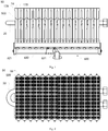
- the present embodiment provides a burner 50 including a plurality of distributors 500 arranged in a horizontal direction.
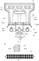
- Fig. 3 shows a right side view of one of the distributors 500.
- the distributor 500 of the present embodiment includes a gas mixing cavity 12 and a plurality of injection pipes 510.
- the number of the injection pipes 510 may be three or more.
- the plurality of injection pipes 510 are independent of each other, and each of the injection pipes 510 is in communication with the gas mixing cavity 12.
- the plurality of injection pipes 510 can inject a larger amount of gas and improve the ejecting ability, thereby greatly improving combustion heat intensity and heat load of the burner, making the gas combustion more complete, and reducing generation of nitrogen oxides.
- the present embodiment is exemplified by three injection pipes 510, that is, the distributor 500 of the present embodiment includes a first injection pipe 510A, a second injection pipe 510B, and a third injection pipe 510C.
- the first injection pipe 510A, the second injection pipe 510B, and the third injection pipe 510C are vertically arranged, so that the distributor is simple in structure, convenient to manufacture, and low in cost.
- the first injection pipe 510A, the second injection pipe 510B, and the third injection pipe 510C may be uniformly distributed at equal intervals, or may be randomly distributed at unequal intervals.
- the injection pipe 510 of the embodiment of the present disclosure will be described in detail in the preferred manner with reference to the accompanying drawings. Since the first injection pipe 510A, the second injection pipe 510B and the third injection pipe 510C preferably have the same shape, the following description will only take the first ejector tube 510A as an example.
- An end surface of a gas outlet end (gas outlet section) 511 of the first injection pipe 510A is inclined to two sides to form a flow guiding inclined surface 511A, so as to reduce an injection pressure of gas at the gas outlet end (gas outlet section) 511, guide the gas ejected from the gas outlet end (gas outlet section) 511 to flow to two sides, and help the gas to be uniformly mixed in the gas mixing cavity 12.
- a width D1 of the gas outlet end (gas outlet section) 511 of the first injection pipe 510A is preferably greater than a width D2 of the gas inlet end 512, so that a size of the distributor 500 can be reduced as much as possible, and the gas can be uniformly mixed as much as possible after being ejected from the gas outlet end (gas outlet section) 511.
- Fig. 4 illustrates a left side view of the distributor 500 of the present embodiment.
- the burner 50 further includes a gas distributor 600 disposed below the first injection pipe 510A, the second injection pipe 510B, and the third injection pipe 510C of the distributor 500.
- a plurality of gas channels 610 is defined in the gas distributor 600, and the number and distribution of the gas channels 610 should correspond to the number and distribution of the injection pipes 510.
- the gas distributor 600 includes a first gas channel 611, a second gas channel 612 and a third gas channel 613.
- the first gas channel 611 communicates with the first injection pipe 510A through a first nozzle 621; the second gas channel 612 is communicated with the second injection pipe 510B through a second nozzle 622; and the third gas channel 613 communicates with the third injection pipe 510C through a third nozzle 623.
- the gas distributor 600 is fixedly connected with the first injection pipe 510A, the second injection pipe 510B and the third injection pipe 510C through a bracket 18. It should be noted that since the second gas channel 612 and the second nozzle 622 are blocked by the bracket 18 in Fig. 4 , the second gas channel 612 and the second nozzle 622 are shown by dotted lines.
- the gas distributor 600 includes a gas distribution rod 630 disposed perpendicularly to each gas channel (the first gas channel 611, the second gas channel 612, and the third gas channel 613), a gas channel is defined inside the gas distribution rod 630, and the gas distribution rod 630 has a branch passage hole 631 to communicate the first gas channel 611, the second gas channel 612, and the third gas channel 613 with the gas distribution rod 630, respectively.
- the burner of the present embodiment further includes a cooling water pipe 20, which passes through a through hole 14 provided in the distributor 500 and is in close contact with the distributor 500 to reduce cavity temperature of the distributor 500 and prolong service life of the burner.
- the cooling water pipe 20 is a U-shaped pipe, and the distributor 500 is provided with two through holes 14 for the cooling water pipe 20 to pass through.
- the distributor 500 of the present embodiment further includes a top plate 16 that covers a top of the gas mixing cavity 12, and Fig. 5 shows a top view of the top plate 16.
- the top plate 16 has a plurality of fire holes 161, and the plurality of fire holes 161 can be uniformly arranged in groups.
- Each fire hole 161 is strip-shaped with a plurality of protrusions 161A in a middle portion thereof to increase an area of the fire hole 161A to enhance the injection intensity, and the protrusions 161A of adjacent two fire holes 161 are staggered to increase the number and density of the fire holes 161.
- the distributor 500 of the present embodiment includes a first housing 17A and a second housing 17B which are symmetrically disposed forward and backward, that is, the injection pipe 510 is formed by the first housing 17A and the second housing 17B, a cavity of the injection pipe 510 is surrounded by the first housing 17A and the second housing 17B, and the gas mixing chamber 12 is surrounded by the first housing 17A and the second housing 17B.
- the first housing 17A and the second housing 17B are buckled to be connected, and the top plate 16 is welded to the first housing 17A and the second housing 17B respectively. Therefore, a punching process of the distributor 500 of the present embodiment is simple and reliable, which can reduce the production cost and reduce the noise when the burner operates.
- the first housing 17A and the second housing 17B have turnup 141 in a circumferential direction of the through hole 14, so that the cooling water pipe 20 is in close contact with the distributor 500.
- the first housing 17A for enclosing the gas mixing chamber 12 has a first concave part 15A with a surface indentation
- the second housing 17B for enclosing the gas mixing cavity 12 has a second concave part 15B symmetrically disposed with respect to the first concave part 15A in a front and rear direction, and the first concave part 15A and the second concave part 15B are concave toward an inside of the gas mixing cavity 12.
- three groups of the first concave part 15A and the second concave part 15B are provided, which are respectively located above the first injection pipe 510A, the second injection pipe 510B and the third injection pipe 510C, and are used for hold down the airflow and uniformly mixing the air.
- the present embodiment further provides a water heater including the burner according to the above embodiment.
- a water heater including the burner according to the above embodiment.
- Other configurations of the water heater of the present embodiment can adopt various technical solutions those are known to those skilled in the art now and in the future, and will not be described in detail herein.
- the present embodiment further provides a wall-hanging stove including the burner according to the above embodiment.
- a wall-hanging stove including the burner according to the above embodiment.
- Other configurations of the wall-hanging stove of the present embodiment can adopt various technical solutions those are known to those skilled in the art now and in the future, and will not be described in detail herein.
- the burner and the water heater or wall-hanging stove having the same of some embodiments of the present disclosure can greatly improve the ejecting ability and ejector coefficient of the gas, increase the combustion heat intensity and the heat load, make the combustion of the gas more completely, reduce the generation of nitrogen oxides, and reduce the cavity temperature of the distributor, prolong the service life of the burner, reduce the cost, and at the same time improve the performance and adaptability of the burner.
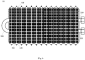
- Fig. 6 illustrates a top view of the burner 10 of the present embodiment.
- the burner 10 of the present embodiment includes a plurality of distributors 100 and cooling water pipes 200 penetrating through the plurality of distributors 100.
- the plurality of distributors 100 is distributed side by side along a width direction of the distributors 100.
- the cooling water pipe 200 is a U-shaped pipe including a water inlet pipe 210 and a water outlet pipe 220 to feed and drain water at a same side of the burner 10.
- the cooling water pipe 200 is integrally formed.
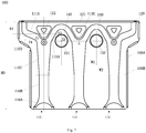
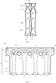
- Fig. 7 illustrates a front view of one of the distributors 100.
- the distributor 100 of the present embodiment includes three injection pipes 110 and two first through holes (the first through hole 131 of the water inlet pipe and the first through hole 132 of the water outlet pipe).
- the two ends of the cooling water pipe 200 respectively pass through the corresponding first through holes, that is, the first through hole 131 of the water inlet pipe is used for the water inlet pipe 210 to pass through and is in close contact with the water inlet pipe 210, and the first through hole 132 of the water outlet pipe is used for the water outlet pipe 220 to pass through and is in close contact with the water outlet pipe 220.
- the distributor 100 also includes a top plate 120 which covers above the three injection pipes 110 and is provided with a plurality of fire holes 121, which can be understood in combination with Fig. 6 .
- a vertical height H0 of the injection pipe 110 is preferably equal to or greater than 95 mm, which can be divided into an ejector section and a gas outlet section 110D according to a gas flow direction (i.e. from bottom to up in Fig. 7 ), the ejector section is sequentially a negative pressure section 110A, a premixing section 110B and a diffuser section 110C according to the gas flow direction.
- the gas outlet section 110D the gas injected by the three injection pipes 110 is mixed again and then discharged from the fire hole 121 and combusted to form a flame.
- an end surface of the gas outlet section 110D of the injection pipe 110 is inclined to two sides to form a flow guiding inclined surface (including a first flow guiding inclined surface 111A inclined to a left side and a second flow guiding inclined surface 111B inclined to a right side); secondly, a hole diameter of the injection pipe 110 in the diffuser section 110C gradually increases in the gas flow direction to reduce the pressure.
- the distributor 100 may be formed by a first housing 100A and a second housing 100B buckled together, i.e., a cavity of the three injection pipes 100 are surrounded by the first housing 100A and the second housing 100B.
- the first through hole 131 of the water inlet pipe and the first through hole 132 of water outlet pipe are formed by opening the first housing 100A and the second housing 100B at symmetrical positions.
- the injection pipe 110 also has a splitter 112, which is disposed at the gas outlet section 110D, i.e., between the first flow guiding inclined surface 111A and the second flow guiding inclined surface 111B.
- the splitter 112 includes a first concave portion 112A formed by recessing the first housing 100A toward the cavity of the injection pipe 110 and a second concave portion 112B formed by recessing the second housing 100B toward the cavity of the injection pipe 110.
- a gas channel is defined between the first concave portion 112A and the second concave portion 112B for gas circulation.
- the splitter 112 is used for splitting gas. That is, a part of the gas is affected by resistance of the splitter 112, split to two sides of the injection pipe 110, and ejected from the fire hole 121 corresponding to two sides of the injection pipe 110, and then combusted to form a flame; while another part of the gas rises vertically upward from the gas channel between the first concave portion 112A and the second concave portion 112B, and is ejected from the fire hole 121 corresponding to a center of the injection pipe 110, and then combusted to form a flame.
- An angle ⁇ of a vertex angle part 112C of the splitter 112 is preferably 45 degrees (°) to 85°, that is, the angle at which the vertex angle part 112C divides the gas to two sides thereof is preferably 45 ° to 85 °, so as to reduce the flow dividing resistance, reduce a transverse dimension of the splitter 112, and further provide conditions for moving up positions of the first through hole 131 of the water inlet pipe and the first through hole 132 of the water outlet pipe.
- the first through hole 131 of the water inlet pipe and the first through hole 132 of the water outlet pipe are respectively located between two adjacent injection pipes 110 and have the same diameter.
- the diameters of the first through hole 131 of the water inlet pipe and the first through hole 132 of the water outlet pipe should be adapted to the cooling water pipe 200, preferably greater than or equal to 11mm, further preferably greater than or equal to 13mm. A greater diameter can increase a contact area with the cooling water pipe 200 and improve the cooling efficiency.
- a horizontal distance between center points of the first through hole 131 of the water inlet pipe and the first through hole 132 of the water outlet pipe forms a first width W1
- a horizontal distance between center lines of two outside injection pipes 110 forms a second width W2
- the first width W1 is preferably half of the second width W2, so as to ensure that the entire area of the top plate 120 can be involved, thereby improving the cooling efficiency.
- a top of the first through hole 131 of the water inlet pipe and a top of the first through hole 132 of the water outlet pipe are preferably arranged at the same horizontal plane.
- the top E1 of the first through hole 131 of the water inlet pipe should be higher than a bottom E2 of the splitter 112. Further, a center point E3 of the first through hole 131 of the water inlet pipe should be higher than a bottom E4 of the outlet section 110D, so that the position of the cooling water pipe 200 is adjacent to the top plate 120, thereby improving the cooling efficiency.
- a vertical distance HI between the first through hole 131 of the water inlet pipe and the top plate 120 is less than or equal to 20 mm; a ratio of the vertical spacing HI to the vertical height H0 of the injection pipe 110 is less than or equal to 20%; and the vertical distance HI is less than or equal to 50% of W1, so that the position of the cooling water pipe 200 is as adjacent to the top plate 120 as possible.
- Nitric oxide accounts for 90% and nitrogen dioxide accounts for 5% ⁇ 10% of the nitrogen oxides produced by the burner, of which nitrogen oxides produced by thermal oxidation reaction account for the majority (thermal oxidation reaction refers to the oxidation reaction of nitrogen and oxygen in air at high temperature to generate nitrogen oxides).
- thermal oxidation reaction refers to the oxidation reaction of nitrogen and oxygen in air at high temperature to generate nitrogen oxides.
- the cooling water pipe 200 can cool the burner, especially reduce the temperature of the top plate 120.
- the positions of the first through hole 131 of the water inlet pipe and the first through hole 132 of the water outlet pipe are designed so that the position of the cooling water pipe 200 can be as adjacent to the top plate 120 as possible and the entire area of the top plate 120 can be involved. Therefore, the burner of the present embodiment can improve the cooling efficiency of the top plate 120 and further keep the top plate 120 at a lower temperature value to reduce thermal oxidation reaction and further reduce nitrogen oxide emission.
- the burner 10 of the present embodiment can cool the top plate 120 and the fire hole 121, prolong the service life of the burner, and can also reduce the burning speed, thereby effectively controlling the occurrence of the tempering phenomenon and improving the safety factor.
- the outer circumferences of the first through hole 131 of the water inlet pipe and the first through hole 132 of the water outlet pipe have turnups 140, so that the cooling water pipe 200 is in close contact with the first through hole 131 of the water inlet pipe and the first through hole 132 of the water outlet pipe.
- the present embodiment further provides a gas water heater including the burner according to the above embodiment.
- a gas water heater including the burner according to the above embodiment.
- Other configurations of the gas water heater of the present embodiment can adopt various technical solutions those are known to those skilled in the art now and in the future, and will not be described in detail herein.
- the present embodiment further provides a wall-hanging stove including the burner according to the above embodiment.
- a wall-hanging stove including the burner according to the above embodiment.
- Other configurations of the wall-hanging stove of the present embodiment can adopt various technical solutions those are known to those skilled in the art now and in the future, and will not be described in detail herein.
- the present embodiment provides a burner, a water heater and a wall-hanging stove having the same.
- a distributor 300 of the present embodiment has four injection pipes 110, and a first through hole is provided between every two adjacent injection pipes 110, i.e., the distributor 300 includes three first through holes (a first through hole 131 of the water inlet pipe, a first through hole 132 of the water outlet pipe, and a first through hole 333 of an intermediate pipe).
- the cooling water pipe is a serpentine pipe and passes through each first through hole in a circuitous way, that is, the water inlet pipe passes through the first through hole 131 of the water inlet pipe, the water outlet pipe passes through the first through hole 132 of the water outlet pipe, and the pipe connecting the water inlet pipe and the water outlet pipe passes through the first through hole 333 of the intermediate pipe, so as to respectively feed and drain water on two sides of the burner.
- the size and position of the first through hole 333 of the intermediate pipe are designed to be the same as those of the first through hole 131 of the water inlet pipe. Therefore, the position of the cooling water pipe can be as adjacent to the top plate 120 as possible and the entire area of the top plate 120 can be involved. Therefore, the burner of the present embodiment can improve the cooling efficiency of the top plate 120 and further keep the top plate 120 at a lower temperature value to reduce the emission of nitrogen oxides.
- the above embodiments provide a variety of burners, as well as gas water heaters and wall-hanging stove based on the above burners.
- the cooling water pipe is further made adjacent to the top plate and the fire hole by arranging the first through hole for the cooling water pipe to pass through between adjacent injection pipes and making the position of the first through hole adjacent to the top plate, so as to improve the cooling efficiency of the top plate and reduce the emission of nitrogen oxides.
- the design of multiple injection pipes can increase the ejector coefficient and the amount of ejected air, thus improving the combustion efficiency.
- the embodiment of the present disclosure does not limit the number of injection pipes and the number of first through holes.
- a first through hole may be provided between every two adjacent injection pipes, i.e., an even number of first through holes may be provided, at the same time the cooling water pipes feed and drain water at the same side of the burner.
- a first through hole may be provided between every two adjacent injection pipes, i.e., an odd number of first through holes may be provided, at the same time the cooling water pipes feed and drain water on two sides of the burner respectively.
- the present embodiment provides a burner 40, a water heater and a wall-hanging stove having the same.
- a distributor 400 further includes two second through holes (the first through hole 231 of the water inlet pipe and the first through hole 232 of the water outlet pipe).
- the two ends of the cooling water pipe 200 respectively pass through the corresponding second through holes, i.e., the second through hole 231 of the water inlet pipe is used for the water inlet pipe 210 to pass through and is in close contact with the water inlet pipe 210, and the second through hole 232 of the water outlet pipe is used for the water outlet pipe 220 to pass through and is in close contact with the water outlet pipe 220, which can be understood in combination with Figs. 10 and 11 .
- the tops of the second through hole 231 of the water inlet pipe and the second through hole 232 of the water outlet pipe are preferably disposed at the same horizontal plane, and the top portion E11 of the second through hole 231 of the water inlet pipe and the second through hole 232 of the water outlet pipe may be lower than the bottom portion E2 of the splitter 112. Therefore, the second through hole match with the first through hole (131/132) so that the position of the cooling water pipe 200 can be adjacent to the top plate 120 or slightly lower than the splitter 112, thereby improving the cooling efficiency.
- the second through hole 231 of the water inlet pipe and the second through hole 232 of the water outlet pipe may also be in the same height plane as the first through hole 131 of the water inlet pipe and the first through hole 132 of the water outlet pipe.
- the cooling water pipe in the present embodiment can be a serpentine pipe, which penetrates through the second through hole on one side, the plurality of distributors, the first through hole, and finally the second through hole on the other side in a circuitous way.
- the cooling water pipe can also be a plurality of U-shaped pipes which respectively penetrate through the first through hole, the plurality of distributors, and then the second through hole; or respectively penetrate in and out through the first through hole and penetrate in and out through the second through hole.
- the inlet end and the outlet end for the cooling water pipe may be located at one side of the burner or at two sides of the burner, and there is no specific limitation here.
Landscapes
- Engineering & Computer Science (AREA)
- Chemical & Material Sciences (AREA)
- Combustion & Propulsion (AREA)
- Mechanical Engineering (AREA)
- General Engineering & Computer Science (AREA)
- Gas Burners (AREA)
Applications Claiming Priority (3)
| Application Number | Priority Date | Filing Date | Title |
|---|---|---|---|
| CN201810039045.8A CN109724078B (zh) | 2018-01-16 | 2018-01-16 | 分火器及具有其的燃烧器和热水器 |
| CN201810461364.8A CN108443880B (zh) | 2018-05-15 | 2018-05-15 | 分火器及应用其的燃烧器和热水器 |
| PCT/CN2018/091100 WO2019140861A1 (zh) | 2018-01-16 | 2018-06-13 | 分火器及应用其的燃烧器和热水器 |
Publications (3)
| Publication Number | Publication Date |
|---|---|
| EP3584499A1 true EP3584499A1 (de) | 2019-12-25 |
| EP3584499A4 EP3584499A4 (de) | 2020-02-19 |
| EP3584499B1 EP3584499B1 (de) | 2021-02-17 |
Family
ID=67301961
Family Applications (1)
| Application Number | Title | Priority Date | Filing Date |
|---|---|---|---|
| EP18900678.6A Active EP3584499B1 (de) | 2018-01-16 | 2018-06-13 | Flammenverteiler sowie brenner und wassererhitzer mit verwendung davon |
Country Status (4)
| Country | Link |
|---|---|
| EP (1) | EP3584499B1 (de) |
| ES (1) | ES2870659T3 (de) |
| PT (1) | PT3584499T (de) |
| WO (1) | WO2019140861A1 (de) |
Cited By (1)
| Publication number | Priority date | Publication date | Assignee | Title |
|---|---|---|---|---|
| EP3597999B1 (de) * | 2018-07-20 | 2021-03-17 | Guangdong Vanward New Electric Co., Ltd. | Gas-wassererhitzer und brenner dafür |
Family Cites Families (9)
| Publication number | Priority date | Publication date | Assignee | Title |
|---|---|---|---|---|
| AT395759B (de) * | 1991-03-12 | 1993-03-25 | Vaillant Gmbh | Gasbrenner |
| FR2740202B1 (fr) * | 1995-10-19 | 1997-12-12 | Leblanc Sa E L M | Perfectionnements apportes a un bruleur de chauffe-eau, chauffe-bain, chaudiere a gaz |
| DE19542649A1 (de) * | 1995-11-15 | 1997-05-22 | Bosch Gmbh Robert | Atmosphärischer, wassergekühlter Gasbrenner |
| KR101025703B1 (ko) * | 2009-07-22 | 2011-03-30 | 주식회사 경동나비엔 | 가스 버너 |
| CN202253640U (zh) * | 2011-10-05 | 2012-05-30 | 广东万和新电气股份有限公司 | 燃气热水器的燃烧器 |
| CN204227677U (zh) * | 2014-11-05 | 2015-03-25 | 广东万和新电气股份有限公司 | 燃气采暖热水炉 |
| CN206582843U (zh) * | 2017-01-27 | 2017-10-24 | 黄婉平 | 一种燃气采暖热水炉的低氮氧化物燃烧器 |
| CN106642109B (zh) * | 2017-01-27 | 2023-03-10 | 黄婉平 | 一种燃气采暖热水炉的低氮氧化物燃烧器 |
| CN206739297U (zh) * | 2017-04-01 | 2017-12-12 | 浙江森歌电器有限公司 | 灶具燃烧器 |
-
2018
- 2018-06-13 WO PCT/CN2018/091100 patent/WO2019140861A1/zh not_active Ceased
- 2018-06-13 PT PT189006786T patent/PT3584499T/pt unknown
- 2018-06-13 EP EP18900678.6A patent/EP3584499B1/de active Active
- 2018-06-13 ES ES18900678T patent/ES2870659T3/es active Active
Cited By (1)
| Publication number | Priority date | Publication date | Assignee | Title |
|---|---|---|---|---|
| EP3597999B1 (de) * | 2018-07-20 | 2021-03-17 | Guangdong Vanward New Electric Co., Ltd. | Gas-wassererhitzer und brenner dafür |
Also Published As
| Publication number | Publication date |
|---|---|
| WO2019140861A1 (zh) | 2019-07-25 |
| EP3584499A4 (de) | 2020-02-19 |
| PT3584499T (pt) | 2021-05-24 |
| ES2870659T3 (es) | 2021-10-27 |
| EP3584499B1 (de) | 2021-02-17 |
Similar Documents
| Publication | Publication Date | Title |
|---|---|---|
| CN106642109B (zh) | 一种燃气采暖热水炉的低氮氧化物燃烧器 | |
| CN203687036U (zh) | 燃气热水器的燃烧器及燃气热水器 | |
| EP3795900B1 (de) | Brennkammer und wassererhitzer mit verwendung davon | |
| CN112113340B (zh) | 一种新型浓淡燃烧火排、燃烧器及热水器 | |
| CN112212328B (zh) | 燃烧器及其应用 | |
| CN207065570U (zh) | 燃烧器及燃气热水器 | |
| KR100495505B1 (ko) | 다단제어를 구현하는 가스연소 버너 | |
| CN204513788U (zh) | 一种热水器的燃烧器火排 | |
| EP3584499B1 (de) | Flammenverteiler sowie brenner und wassererhitzer mit verwendung davon | |
| US12474047B2 (en) | Burner and applications thereof | |
| CN222143042U (zh) | 火排及燃烧器 | |
| CN108443880B (zh) | 分火器及应用其的燃烧器和热水器 | |
| CN202132950U (zh) | 扁平燃烧装置 | |
| KR100466178B1 (ko) | 연료 분할 분사형 연료노즐을 구비한 저질소산화물 축열식복사관 버너 | |
| US3958762A (en) | Gas burner | |
| CN209991765U (zh) | 一种可快速升温的工业炉 | |
| CN109724078B (zh) | 分火器及具有其的燃烧器和热水器 | |
| CN222143058U (zh) | 火排及燃烧器 | |
| CN213542467U (zh) | 水冷燃烧器及具有其的燃气热水器 | |
| CN221375666U (zh) | 燃烧器及生活电器 | |
| CN217560086U (zh) | 一种双火排对接式风冷燃气热水器 | |
| CN222836864U (zh) | 燃烧头、燃烧器及热水器 | |
| CN218993392U (zh) | 火排组件及燃烧器 | |
| CN213513873U (zh) | 一种燃烧器及热水器 | |
| US12618554B2 (en) | Burner component and burner |
Legal Events
| Date | Code | Title | Description |
|---|---|---|---|
| STAA | Information on the status of an ep patent application or granted ep patent |
Free format text: STATUS: THE INTERNATIONAL PUBLICATION HAS BEEN MADE |
|
| PUAI | Public reference made under article 153(3) epc to a published international application that has entered the european phase |
Free format text: ORIGINAL CODE: 0009012 |
|
| STAA | Information on the status of an ep patent application or granted ep patent |
Free format text: STATUS: REQUEST FOR EXAMINATION WAS MADE |
|
| 17P | Request for examination filed |
Effective date: 20190918 |
|
| AK | Designated contracting states |
Kind code of ref document: A1 Designated state(s): AL AT BE BG CH CY CZ DE DK EE ES FI FR GB GR HR HU IE IS IT LI LT LU LV MC MK MT NL NO PL PT RO RS SE SI SK SM TR |
|
| AX | Request for extension of the european patent |
Extension state: BA ME |
|
| A4 | Supplementary search report drawn up and despatched |
Effective date: 20200120 |
|
| RIC1 | Information provided on ipc code assigned before grant |
Ipc: F23D 14/04 20060101AFI20200114BHEP Ipc: F23D 14/78 20060101ALI20200114BHEP |
|
| GRAP | Despatch of communication of intention to grant a patent |
Free format text: ORIGINAL CODE: EPIDOSNIGR1 |
|
| STAA | Information on the status of an ep patent application or granted ep patent |
Free format text: STATUS: GRANT OF PATENT IS INTENDED |
|
| INTG | Intention to grant announced |
Effective date: 20201110 |
|
| GRAS | Grant fee paid |
Free format text: ORIGINAL CODE: EPIDOSNIGR3 |
|
| GRAA | (expected) grant |
Free format text: ORIGINAL CODE: 0009210 |
|
| STAA | Information on the status of an ep patent application or granted ep patent |
Free format text: STATUS: THE PATENT HAS BEEN GRANTED |
|
| AK | Designated contracting states |
Kind code of ref document: B1 Designated state(s): AL AT BE BG CH CY CZ DE DK EE ES FI FR GB GR HR HU IE IS IT LI LT LU LV MC MK MT NL NO PL PT RO RS SE SI SK SM TR |
|
| DAV | Request for validation of the european patent (deleted) | ||
| DAX | Request for extension of the european patent (deleted) | ||
| REG | Reference to a national code |
Ref country code: GB Ref legal event code: FG4D |
|
| REG | Reference to a national code |
Ref country code: CH Ref legal event code: EP |
|
| REG | Reference to a national code |
Ref country code: DE Ref legal event code: R096 Ref document number: 602018012825 Country of ref document: DE |
|
| REG | Reference to a national code |
Ref country code: AT Ref legal event code: REF Ref document number: 1361949 Country of ref document: AT Kind code of ref document: T Effective date: 20210315 |
|
| REG | Reference to a national code |
Ref country code: IE Ref legal event code: FG4D |
|
| REG | Reference to a national code |
Ref country code: PT Ref legal event code: SC4A Ref document number: 3584499 Country of ref document: PT Date of ref document: 20210524 Kind code of ref document: T Free format text: AVAILABILITY OF NATIONAL TRANSLATION Effective date: 20210517 |
|
| REG | Reference to a national code |
Ref country code: LT Ref legal event code: MG9D |
|
| REG | Reference to a national code |
Ref country code: NL Ref legal event code: MP Effective date: 20210217 |
|
| PG25 | Lapsed in a contracting state [announced via postgrant information from national office to epo] |
Ref country code: NO Free format text: LAPSE BECAUSE OF FAILURE TO SUBMIT A TRANSLATION OF THE DESCRIPTION OR TO PAY THE FEE WITHIN THE PRESCRIBED TIME-LIMIT Effective date: 20210517 Ref country code: LT Free format text: LAPSE BECAUSE OF FAILURE TO SUBMIT A TRANSLATION OF THE DESCRIPTION OR TO PAY THE FEE WITHIN THE PRESCRIBED TIME-LIMIT Effective date: 20210217 Ref country code: BG Free format text: LAPSE BECAUSE OF FAILURE TO SUBMIT A TRANSLATION OF THE DESCRIPTION OR TO PAY THE FEE WITHIN THE PRESCRIBED TIME-LIMIT Effective date: 20210517 Ref country code: FI Free format text: LAPSE BECAUSE OF FAILURE TO SUBMIT A TRANSLATION OF THE DESCRIPTION OR TO PAY THE FEE WITHIN THE PRESCRIBED TIME-LIMIT Effective date: 20210217 Ref country code: GR Free format text: LAPSE BECAUSE OF FAILURE TO SUBMIT A TRANSLATION OF THE DESCRIPTION OR TO PAY THE FEE WITHIN THE PRESCRIBED TIME-LIMIT Effective date: 20210518 Ref country code: HR Free format text: LAPSE BECAUSE OF FAILURE TO SUBMIT A TRANSLATION OF THE DESCRIPTION OR TO PAY THE FEE WITHIN THE PRESCRIBED TIME-LIMIT Effective date: 20210217 |
|
| REG | Reference to a national code |
Ref country code: AT Ref legal event code: MK05 Ref document number: 1361949 Country of ref document: AT Kind code of ref document: T Effective date: 20210217 |
|
| PG25 | Lapsed in a contracting state [announced via postgrant information from national office to epo] |
Ref country code: SE Free format text: LAPSE BECAUSE OF FAILURE TO SUBMIT A TRANSLATION OF THE DESCRIPTION OR TO PAY THE FEE WITHIN THE PRESCRIBED TIME-LIMIT Effective date: 20210217 Ref country code: RS Free format text: LAPSE BECAUSE OF FAILURE TO SUBMIT A TRANSLATION OF THE DESCRIPTION OR TO PAY THE FEE WITHIN THE PRESCRIBED TIME-LIMIT Effective date: 20210217 Ref country code: LV Free format text: LAPSE BECAUSE OF FAILURE TO SUBMIT A TRANSLATION OF THE DESCRIPTION OR TO PAY THE FEE WITHIN THE PRESCRIBED TIME-LIMIT Effective date: 20210217 Ref country code: PL Free format text: LAPSE BECAUSE OF FAILURE TO SUBMIT A TRANSLATION OF THE DESCRIPTION OR TO PAY THE FEE WITHIN THE PRESCRIBED TIME-LIMIT Effective date: 20210217 Ref country code: NL Free format text: LAPSE BECAUSE OF FAILURE TO SUBMIT A TRANSLATION OF THE DESCRIPTION OR TO PAY THE FEE WITHIN THE PRESCRIBED TIME-LIMIT Effective date: 20210217 |
|
| PG25 | Lapsed in a contracting state [announced via postgrant information from national office to epo] |
Ref country code: IS Free format text: LAPSE BECAUSE OF FAILURE TO SUBMIT A TRANSLATION OF THE DESCRIPTION OR TO PAY THE FEE WITHIN THE PRESCRIBED TIME-LIMIT Effective date: 20210617 |
|
| REG | Reference to a national code |
Ref country code: ES Ref legal event code: FG2A Ref document number: 2870659 Country of ref document: ES Kind code of ref document: T3 Effective date: 20211027 |
|
| PG25 | Lapsed in a contracting state [announced via postgrant information from national office to epo] |
Ref country code: SM Free format text: LAPSE BECAUSE OF FAILURE TO SUBMIT A TRANSLATION OF THE DESCRIPTION OR TO PAY THE FEE WITHIN THE PRESCRIBED TIME-LIMIT Effective date: 20210217 Ref country code: AT Free format text: LAPSE BECAUSE OF FAILURE TO SUBMIT A TRANSLATION OF THE DESCRIPTION OR TO PAY THE FEE WITHIN THE PRESCRIBED TIME-LIMIT Effective date: 20210217 Ref country code: CZ Free format text: LAPSE BECAUSE OF FAILURE TO SUBMIT A TRANSLATION OF THE DESCRIPTION OR TO PAY THE FEE WITHIN THE PRESCRIBED TIME-LIMIT Effective date: 20210217 Ref country code: EE Free format text: LAPSE BECAUSE OF FAILURE TO SUBMIT A TRANSLATION OF THE DESCRIPTION OR TO PAY THE FEE WITHIN THE PRESCRIBED TIME-LIMIT Effective date: 20210217 |
|
| REG | Reference to a national code |
Ref country code: DE Ref legal event code: R097 Ref document number: 602018012825 Country of ref document: DE |
|
| PG25 | Lapsed in a contracting state [announced via postgrant information from national office to epo] |
Ref country code: DK Free format text: LAPSE BECAUSE OF FAILURE TO SUBMIT A TRANSLATION OF THE DESCRIPTION OR TO PAY THE FEE WITHIN THE PRESCRIBED TIME-LIMIT Effective date: 20210217 Ref country code: SK Free format text: LAPSE BECAUSE OF FAILURE TO SUBMIT A TRANSLATION OF THE DESCRIPTION OR TO PAY THE FEE WITHIN THE PRESCRIBED TIME-LIMIT Effective date: 20210217 Ref country code: RO Free format text: LAPSE BECAUSE OF FAILURE TO SUBMIT A TRANSLATION OF THE DESCRIPTION OR TO PAY THE FEE WITHIN THE PRESCRIBED TIME-LIMIT Effective date: 20210217 |
|
| PLBE | No opposition filed within time limit |
Free format text: ORIGINAL CODE: 0009261 |
|
| STAA | Information on the status of an ep patent application or granted ep patent |
Free format text: STATUS: NO OPPOSITION FILED WITHIN TIME LIMIT |
|
| 26N | No opposition filed |
Effective date: 20211118 |
|
| PG25 | Lapsed in a contracting state [announced via postgrant information from national office to epo] |
Ref country code: MC Free format text: LAPSE BECAUSE OF FAILURE TO SUBMIT A TRANSLATION OF THE DESCRIPTION OR TO PAY THE FEE WITHIN THE PRESCRIBED TIME-LIMIT Effective date: 20210217 Ref country code: AL Free format text: LAPSE BECAUSE OF FAILURE TO SUBMIT A TRANSLATION OF THE DESCRIPTION OR TO PAY THE FEE WITHIN THE PRESCRIBED TIME-LIMIT Effective date: 20210217 |
|
| REG | Reference to a national code |
Ref country code: CH Ref legal event code: PL |
|
| PG25 | Lapsed in a contracting state [announced via postgrant information from national office to epo] |
Ref country code: SI Free format text: LAPSE BECAUSE OF FAILURE TO SUBMIT A TRANSLATION OF THE DESCRIPTION OR TO PAY THE FEE WITHIN THE PRESCRIBED TIME-LIMIT Effective date: 20210217 |
|
| REG | Reference to a national code |
Ref country code: BE Ref legal event code: MM Effective date: 20210630 |
|
| PG25 | Lapsed in a contracting state [announced via postgrant information from national office to epo] |
Ref country code: LU Free format text: LAPSE BECAUSE OF NON-PAYMENT OF DUE FEES Effective date: 20210613 |
|
| PG25 | Lapsed in a contracting state [announced via postgrant information from national office to epo] |
Ref country code: IE Free format text: LAPSE BECAUSE OF NON-PAYMENT OF DUE FEES Effective date: 20210613 Ref country code: CH Free format text: LAPSE BECAUSE OF NON-PAYMENT OF DUE FEES Effective date: 20210630 Ref country code: LI Free format text: LAPSE BECAUSE OF NON-PAYMENT OF DUE FEES Effective date: 20210630 |
|
| PG25 | Lapsed in a contracting state [announced via postgrant information from national office to epo] |
Ref country code: IS Free format text: LAPSE BECAUSE OF FAILURE TO SUBMIT A TRANSLATION OF THE DESCRIPTION OR TO PAY THE FEE WITHIN THE PRESCRIBED TIME-LIMIT Effective date: 20210617 |
|
| PG25 | Lapsed in a contracting state [announced via postgrant information from national office to epo] |
Ref country code: BE Free format text: LAPSE BECAUSE OF NON-PAYMENT OF DUE FEES Effective date: 20210630 |
|
| PG25 | Lapsed in a contracting state [announced via postgrant information from national office to epo] |
Ref country code: CY Free format text: LAPSE BECAUSE OF FAILURE TO SUBMIT A TRANSLATION OF THE DESCRIPTION OR TO PAY THE FEE WITHIN THE PRESCRIBED TIME-LIMIT Effective date: 20210217 |
|
| P01 | Opt-out of the competence of the unified patent court (upc) registered |
Effective date: 20230526 |
|
| PG25 | Lapsed in a contracting state [announced via postgrant information from national office to epo] |
Ref country code: HU Free format text: LAPSE BECAUSE OF FAILURE TO SUBMIT A TRANSLATION OF THE DESCRIPTION OR TO PAY THE FEE WITHIN THE PRESCRIBED TIME-LIMIT; INVALID AB INITIO Effective date: 20180613 |
|
| PG25 | Lapsed in a contracting state [announced via postgrant information from national office to epo] |
Ref country code: MK Free format text: LAPSE BECAUSE OF FAILURE TO SUBMIT A TRANSLATION OF THE DESCRIPTION OR TO PAY THE FEE WITHIN THE PRESCRIBED TIME-LIMIT Effective date: 20210217 |
|
| PG25 | Lapsed in a contracting state [announced via postgrant information from national office to epo] |
Ref country code: TR Free format text: LAPSE BECAUSE OF FAILURE TO SUBMIT A TRANSLATION OF THE DESCRIPTION OR TO PAY THE FEE WITHIN THE PRESCRIBED TIME-LIMIT Effective date: 20210217 |
|
| PG25 | Lapsed in a contracting state [announced via postgrant information from national office to epo] |
Ref country code: MT Free format text: LAPSE BECAUSE OF FAILURE TO SUBMIT A TRANSLATION OF THE DESCRIPTION OR TO PAY THE FEE WITHIN THE PRESCRIBED TIME-LIMIT Effective date: 20210217 |
|
| PGFP | Annual fee paid to national office [announced via postgrant information from national office to epo] |
Ref country code: DE Payment date: 20250625 Year of fee payment: 8 |
|
| PGFP | Annual fee paid to national office [announced via postgrant information from national office to epo] |
Ref country code: GB Payment date: 20250620 Year of fee payment: 8 |
|
| PGFP | Annual fee paid to national office [announced via postgrant information from national office to epo] |
Ref country code: PT Payment date: 20250528 Year of fee payment: 8 |
|
| PGFP | Annual fee paid to national office [announced via postgrant information from national office to epo] |
Ref country code: FR Payment date: 20250620 Year of fee payment: 8 |
|
| PGFP | Annual fee paid to national office [announced via postgrant information from national office to epo] |
Ref country code: ES Payment date: 20250702 Year of fee payment: 8 |
|
| PGFP | Annual fee paid to national office [announced via postgrant information from national office to epo] |
Ref country code: IT Payment date: 20250619 Year of fee payment: 8 |