EP3584412A2 - Thermisch reagierende kühlungsdurchflussmesser - Google Patents
Thermisch reagierende kühlungsdurchflussmesser Download PDFInfo
- Publication number
- EP3584412A2 EP3584412A2 EP19179398.3A EP19179398A EP3584412A2 EP 3584412 A2 EP3584412 A2 EP 3584412A2 EP 19179398 A EP19179398 A EP 19179398A EP 3584412 A2 EP3584412 A2 EP 3584412A2
- Authority
- EP
- European Patent Office
- Prior art keywords
- coil
- plate
- thermally responsive
- airflow
- flow meter
- Prior art date
- Legal status (The legal status is an assumption and is not a legal conclusion. Google has not performed a legal analysis and makes no representation as to the accuracy of the status listed.)
- Granted
Links
- 238000001816 cooling Methods 0.000 title claims description 40
- 230000004044 response Effects 0.000 claims abstract description 19
- 230000008859 change Effects 0.000 claims description 4
- 239000007789 gas Substances 0.000 description 19
- 230000007423 decrease Effects 0.000 description 11
- 238000000034 method Methods 0.000 description 9
- PXHVJJICTQNCMI-UHFFFAOYSA-N Nickel Chemical compound [Ni] PXHVJJICTQNCMI-UHFFFAOYSA-N 0.000 description 6
- 230000008901 benefit Effects 0.000 description 6
- 230000008602 contraction Effects 0.000 description 4
- 239000000446 fuel Substances 0.000 description 4
- 239000000463 material Substances 0.000 description 4
- 229910052759 nickel Inorganic materials 0.000 description 3
- 230000008569 process Effects 0.000 description 3
- 229910045601 alloy Inorganic materials 0.000 description 2
- 239000000956 alloy Substances 0.000 description 2
- 230000000712 assembly Effects 0.000 description 2
- 238000000429 assembly Methods 0.000 description 2
- 239000012809 cooling fluid Substances 0.000 description 2
- 230000003247 decreasing effect Effects 0.000 description 2
- 238000010248 power generation Methods 0.000 description 2
- 230000003068 static effect Effects 0.000 description 2
- 230000006978 adaptation Effects 0.000 description 1
- 239000000567 combustion gas Substances 0.000 description 1
- 238000004891 communication Methods 0.000 description 1
- 230000006835 compression Effects 0.000 description 1
- 238000007906 compression Methods 0.000 description 1
- 238000010276 construction Methods 0.000 description 1
- 230000008878 coupling Effects 0.000 description 1
- 238000010168 coupling process Methods 0.000 description 1
- 238000005859 coupling reaction Methods 0.000 description 1
- 230000012447 hatching Effects 0.000 description 1
- 230000001105 regulatory effect Effects 0.000 description 1
- 229910000601 superalloy Inorganic materials 0.000 description 1
Images


Classifications
-
- F—MECHANICAL ENGINEERING; LIGHTING; HEATING; WEAPONS; BLASTING
- F01—MACHINES OR ENGINES IN GENERAL; ENGINE PLANTS IN GENERAL; STEAM ENGINES
- F01D—NON-POSITIVE DISPLACEMENT MACHINES OR ENGINES, e.g. STEAM TURBINES
- F01D25/00—Component parts, details, or accessories, not provided for in, or of interest apart from, other groups
- F01D25/08—Cooling; Heating; Heat-insulation
- F01D25/12—Cooling
-
- F—MECHANICAL ENGINEERING; LIGHTING; HEATING; WEAPONS; BLASTING
- F01—MACHINES OR ENGINES IN GENERAL; ENGINE PLANTS IN GENERAL; STEAM ENGINES
- F01D—NON-POSITIVE DISPLACEMENT MACHINES OR ENGINES, e.g. STEAM TURBINES
- F01D9/00—Stators
- F01D9/06—Fluid supply conduits to nozzles or the like
-
- F—MECHANICAL ENGINEERING; LIGHTING; HEATING; WEAPONS; BLASTING
- F01—MACHINES OR ENGINES IN GENERAL; ENGINE PLANTS IN GENERAL; STEAM ENGINES
- F01D—NON-POSITIVE DISPLACEMENT MACHINES OR ENGINES, e.g. STEAM TURBINES
- F01D17/00—Regulating or controlling by varying flow
- F01D17/02—Arrangement of sensing elements
- F01D17/08—Arrangement of sensing elements responsive to condition of working-fluid, e.g. pressure
- F01D17/085—Arrangement of sensing elements responsive to condition of working-fluid, e.g. pressure to temperature
-
- F—MECHANICAL ENGINEERING; LIGHTING; HEATING; WEAPONS; BLASTING
- F01—MACHINES OR ENGINES IN GENERAL; ENGINE PLANTS IN GENERAL; STEAM ENGINES
- F01D—NON-POSITIVE DISPLACEMENT MACHINES OR ENGINES, e.g. STEAM TURBINES
- F01D21/00—Shutting-down of machines or engines, e.g. in emergency; Regulating, controlling, or safety means not otherwise provided for
- F01D21/003—Arrangements for testing or measuring
-
- F—MECHANICAL ENGINEERING; LIGHTING; HEATING; WEAPONS; BLASTING
- F02—COMBUSTION ENGINES; HOT-GAS OR COMBUSTION-PRODUCT ENGINE PLANTS
- F02C—GAS-TURBINE PLANTS; AIR INTAKES FOR JET-PROPULSION PLANTS; CONTROLLING FUEL SUPPLY IN AIR-BREATHING JET-PROPULSION PLANTS
- F02C6/00—Plural gas-turbine plants; Combinations of gas-turbine plants with other apparatus; Adaptations of gas- turbine plants for special use
- F02C6/04—Gas-turbine plants providing heated or pressurised working fluid for other apparatus, e.g. without mechanical power output
- F02C6/06—Gas-turbine plants providing heated or pressurised working fluid for other apparatus, e.g. without mechanical power output providing compressed gas
- F02C6/08—Gas-turbine plants providing heated or pressurised working fluid for other apparatus, e.g. without mechanical power output providing compressed gas the gas being bled from the gas-turbine compressor
-
- F—MECHANICAL ENGINEERING; LIGHTING; HEATING; WEAPONS; BLASTING
- F02—COMBUSTION ENGINES; HOT-GAS OR COMBUSTION-PRODUCT ENGINE PLANTS
- F02C—GAS-TURBINE PLANTS; AIR INTAKES FOR JET-PROPULSION PLANTS; CONTROLLING FUEL SUPPLY IN AIR-BREATHING JET-PROPULSION PLANTS
- F02C7/00—Features, components parts, details or accessories, not provided for in, or of interest apart form groups F02C1/00 - F02C6/00; Air intakes for jet-propulsion plants
- F02C7/12—Cooling of plants
- F02C7/125—Cooling of plants by partial arc admission of the working fluid or by intermittent admission of working and cooling fluid
-
- G—PHYSICS
- G01—MEASURING; TESTING
- G01F—MEASURING VOLUME, VOLUME FLOW, MASS FLOW OR LIQUID LEVEL; METERING BY VOLUME
- G01F1/00—Measuring the volume flow or mass flow of fluid or fluent solid material wherein the fluid passes through a meter in a continuous flow
- G01F1/68—Measuring the volume flow or mass flow of fluid or fluent solid material wherein the fluid passes through a meter in a continuous flow by using thermal effects
-
- F—MECHANICAL ENGINEERING; LIGHTING; HEATING; WEAPONS; BLASTING
- F01—MACHINES OR ENGINES IN GENERAL; ENGINE PLANTS IN GENERAL; STEAM ENGINES
- F01D—NON-POSITIVE DISPLACEMENT MACHINES OR ENGINES, e.g. STEAM TURBINES
- F01D11/00—Preventing or minimising internal leakage of working-fluid, e.g. between stages
- F01D11/005—Sealing means between non relatively rotating elements
-
- F—MECHANICAL ENGINEERING; LIGHTING; HEATING; WEAPONS; BLASTING
- F02—COMBUSTION ENGINES; HOT-GAS OR COMBUSTION-PRODUCT ENGINE PLANTS
- F02C—GAS-TURBINE PLANTS; AIR INTAKES FOR JET-PROPULSION PLANTS; CONTROLLING FUEL SUPPLY IN AIR-BREATHING JET-PROPULSION PLANTS
- F02C7/00—Features, components parts, details or accessories, not provided for in, or of interest apart form groups F02C1/00 - F02C6/00; Air intakes for jet-propulsion plants
- F02C7/12—Cooling of plants
- F02C7/16—Cooling of plants characterised by cooling medium
- F02C7/18—Cooling of plants characterised by cooling medium the medium being gaseous, e.g. air
-
- F—MECHANICAL ENGINEERING; LIGHTING; HEATING; WEAPONS; BLASTING
- F05—INDEXING SCHEMES RELATING TO ENGINES OR PUMPS IN VARIOUS SUBCLASSES OF CLASSES F01-F04
- F05D—INDEXING SCHEME FOR ASPECTS RELATING TO NON-POSITIVE-DISPLACEMENT MACHINES OR ENGINES, GAS-TURBINES OR JET-PROPULSION PLANTS
- F05D2220/00—Application
- F05D2220/30—Application in turbines
- F05D2220/32—Application in turbines in gas turbines
- F05D2220/323—Application in turbines in gas turbines for aircraft propulsion, e.g. jet engines
-
- F—MECHANICAL ENGINEERING; LIGHTING; HEATING; WEAPONS; BLASTING
- F05—INDEXING SCHEMES RELATING TO ENGINES OR PUMPS IN VARIOUS SUBCLASSES OF CLASSES F01-F04
- F05D—INDEXING SCHEME FOR ASPECTS RELATING TO NON-POSITIVE-DISPLACEMENT MACHINES OR ENGINES, GAS-TURBINES OR JET-PROPULSION PLANTS
- F05D2250/00—Geometry
- F05D2250/10—Two-dimensional
- F05D2250/19—Two-dimensional machined; miscellaneous
- F05D2250/191—Two-dimensional machined; miscellaneous perforated
-
- F—MECHANICAL ENGINEERING; LIGHTING; HEATING; WEAPONS; BLASTING
- F05—INDEXING SCHEMES RELATING TO ENGINES OR PUMPS IN VARIOUS SUBCLASSES OF CLASSES F01-F04
- F05D—INDEXING SCHEME FOR ASPECTS RELATING TO NON-POSITIVE-DISPLACEMENT MACHINES OR ENGINES, GAS-TURBINES OR JET-PROPULSION PLANTS
- F05D2250/00—Geometry
- F05D2250/20—Three-dimensional
- F05D2250/25—Three-dimensional helical
-
- F—MECHANICAL ENGINEERING; LIGHTING; HEATING; WEAPONS; BLASTING
- F05—INDEXING SCHEMES RELATING TO ENGINES OR PUMPS IN VARIOUS SUBCLASSES OF CLASSES F01-F04
- F05D—INDEXING SCHEME FOR ASPECTS RELATING TO NON-POSITIVE-DISPLACEMENT MACHINES OR ENGINES, GAS-TURBINES OR JET-PROPULSION PLANTS
- F05D2260/00—Function
- F05D2260/20—Heat transfer, e.g. cooling
-
- F—MECHANICAL ENGINEERING; LIGHTING; HEATING; WEAPONS; BLASTING
- F05—INDEXING SCHEMES RELATING TO ENGINES OR PUMPS IN VARIOUS SUBCLASSES OF CLASSES F01-F04
- F05D—INDEXING SCHEME FOR ASPECTS RELATING TO NON-POSITIVE-DISPLACEMENT MACHINES OR ENGINES, GAS-TURBINES OR JET-PROPULSION PLANTS
- F05D2300/00—Materials; Properties thereof
- F05D2300/50—Intrinsic material properties or characteristics
- F05D2300/502—Thermal properties
- F05D2300/5021—Expansivity
- F05D2300/50212—Expansivity dissimilar
-
- G—PHYSICS
- G01—MEASURING; TESTING
- G01F—MEASURING VOLUME, VOLUME FLOW, MASS FLOW OR LIQUID LEVEL; METERING BY VOLUME
- G01F15/00—Details of, or accessories for, apparatus of groups G01F1/00 - G01F13/00 insofar as such details or appliances are not adapted to particular types of such apparatus
- G01F15/02—Compensating or correcting for variations in pressure, density or temperature
- G01F15/04—Compensating or correcting for variations in pressure, density or temperature of gases to be measured
-
- Y—GENERAL TAGGING OF NEW TECHNOLOGICAL DEVELOPMENTS; GENERAL TAGGING OF CROSS-SECTIONAL TECHNOLOGIES SPANNING OVER SEVERAL SECTIONS OF THE IPC; TECHNICAL SUBJECTS COVERED BY FORMER USPC CROSS-REFERENCE ART COLLECTIONS [XRACs] AND DIGESTS
- Y02—TECHNOLOGIES OR APPLICATIONS FOR MITIGATION OR ADAPTATION AGAINST CLIMATE CHANGE
- Y02T—CLIMATE CHANGE MITIGATION TECHNOLOGIES RELATED TO TRANSPORTATION
- Y02T50/00—Aeronautics or air transport
- Y02T50/60—Efficient propulsion technologies, e.g. for aircraft
Definitions
- the present disclosure relates to flow meters, and more specifically, to thermally responsive flow meters for gas turbine engines.
- Gas turbine engines typically include at least a compressor section to pressurize inflowing air, a combustor section to burn a fuel in the presence of the pressurized air, and a turbine section to extract energy from the resulting combustion gases.
- Gas turbine engines may have various secondary airflow streams to provide cooling air to gas turbine engine components including, for example, stator vane assemblies and/or rotor assemblies in the turbine section. The amount of cooling flow provided to these components may be designed to accommodate the hottest engine operating conditions (i.e., greatest temperatures).
- the thermally responsive flow meter may comprise a coil and a plate coupled to the coil.
- the plate may define a first airflow aperture.
- the plate may be configured to translate in a circumferential direction in response to a thermal expansion of the coil.
- the plate may comprise an annular structure including an inner diameter and an outer diameter radially outward of the inner diameter.
- the coil may be located at the outer diameter of the plate.
- a flange may extend radially outward from a first end of the coil.
- a housing may be disposed around the plate and the coil.
- a first face of the housing may define a second airflow aperture.
- the coil may be located between the plate and a second face of the housing. The coil may bias the plate toward the first face of the housing.
- An axle may extend between the first face of the housing and the second face of the housing. The coil may be configured to translate the plate about the axle.
- the engine section may comprise a flow guide configured to receive a cooling airflow, and a thermally responsive flow meter coupled to the flow guide.
- the flow guide may define a first airflow aperture.
- the thermally responsive flow meter may define a second airflow aperture.
- the thermally responsive flow meter may be configured to translate the second airflow aperture in a circumferential direction in response to a change in temperature of the cooling airflow.
- the thermally responsive flow meter may be configured to align the second airflow aperture with the first airflow aperture at a first flight condition and to misalign the second airflow aperture relative the first airflow aperture at a second flight condition.
- the first flight condition may comprise a take-off condition and the second flight condition may comprise a cruise condition.
- the thermally responsive flow meter may comprise a coil and a plate coupled to the coil.
- the plate may define the second airflow aperture. Thermal expansion of the coil may result in a circumferential translation of the plate.
- the coil may be located at an outer diameter of the plate.
- a flange may extend from the coil.
- a slot defined by the flow guide may engage the flange.
- the thermally responsive flow meter may further comprise a housing located around the coil and the plate.
- the housing may be press fit within the first airflow aperture.
- the gas turbine engine may comprise a combustor section and a turbine section downstream of the combustor section.
- the turbine section may comprise a flow guide configured to receive an airflow and defining, at least, a portion of an airflow path through the turbine section, and a thermally responsive flow meter coupled to the flow guide.
- the flow guide may further define a first airflow aperture.
- the thermally responsive flow meter may define a second airflow aperture.
- the thermally responsive flow meter may be configured to translate the second airflow aperture in response to a change in temperature of the airflow.
- the thermally responsive flow meter may comprise a coil and a plate coupled to the coil.
- the plate may define the second airflow aperture. Thermal expansion of the coil may result in a circumferential translation of the plate.
- a first surface of the flow guide may restrict radially outward translation of the coil.
- the first surface may extend circumferentially about the flow guide.
- a second surface of the flow guide may restrict radially inward translation of the plate.
- the second surface may extend circumferentially about the flow guide.
- the coil may be located over a first radially extending surface of the plate.
- the thermally responsive flow meter may further comprise a housing disposed around the coil and the plate. The coil may be configured to bias the plate toward a radially extending face of the housing. The radially extending face may define a third airflow aperture.
- any reference to singular includes plural embodiments, and any reference to more than one component or step may include a singular embodiment or step.
- any reference to attached, fixed, coupled, connected or the like may include permanent, removable, temporary, partial, full, and/or any other possible attachment option.
- any reference to without contact (or similar phrases) may also include reduced contact or minimal contact.
- tail refers to the direction associated with a tail (e.g., the back end) of an aircraft, or generally, to the direction of exhaust of a gas turbine engine.
- forward refers to the direction associated with a nose (e.g., the front end) of the aircraft, or generally, to the direction of flight or motion.
- a first component that is "radially outward" of a second component means that the first component is positioned at a greater distance away from the engine central longitudinal axis than the second component.
- a first component that is “radially inward” of a second component means that the first component is positioned closer to the engine central longitudinal axis than the second component.
- a first component that is radially inward of a second component rotates through a circumferentially shorter path than the second component.
- the terminology “radially outward” and “radially inward” may also be used relative to references other than the engine central longitudinal axis.
- Gas turbine engines of the present disclosure may include thermally responsive flow meters.
- the thermally responsive flow meters may be configured to regulate a flow of cooling air through a section of the gas turbine engine based on the engine operating condition.
- the thermally responsive flow meters may include a coil configured to thermally expand and contract in response to changes in engine operating temperature.
- the thermally responsive flow meters may increase cooling flow at hotter operating temperatures and decrease cooling flow at cooler operating temperatures. Reducing the amount of air dedicated to cooling may increase the volume of air available for use in the engine core for power generation, which may increase engine and fuel efficiency.
- Gas turbine engine 120 may comprise a two-spool turbofan that generally incorporates a fan section 122, a compressor section 124, a combustor section 126, and a turbine section 128.
- fan section 122 may drive air along a bypass flow-path B
- compressor section 124 may further drive air along a core flow-path C for compression and communication into combustor section 126, and then expansion through turbine section 128.
- turbofan gas turbine engine 120 Although depicted as a turbofan gas turbine engine 120 herein, it should be understood that the concepts described herein are not limited to use with turbofans as the teachings may be applied to other types of turbine engines including multi-spool architectures, as well as industrial gas turbines.
- gas turbine engine 120 may comprise a low speed spool 130 and a high speed spool 132 mounted for rotation about an engine central longitudinal axis A-A' relative to an engine static structure 136 via one or more bearing systems 138 (shown as, for example, bearing system 138-1 and bearing system 138-2 in FIG. 1 ).
- Engine central longitudinal axis A-A' is oriented in the z direction (axial direction) on the provided xyz axes.
- the y direction on the provided xyz axes refers to the radial direction and the x direction on the provided xyz axes refers to the circumferential direction.
- various bearing systems 138 at various locations may alternatively or additionally be provided, including, for example, bearing system 138, bearing system 138-1, and/or bearing system 138-2.
- low speed spool 130 may comprise an inner shaft 140 that interconnects a fan 142, a low pressure compressor 144, and a low pressure turbine 146.
- Inner shaft 140 may be connected to fan 142 through a geared architecture 148 that can drive fan 142 at a lower speed than low speed spool 130.
- Geared architecture 148 may comprise a gear assembly 160 enclosed within a gear housing 162.
- Gear assembly 160 may couple inner shaft 140 to a rotating fan structure.
- High speed spool 132 may comprise an outer shaft 150 that interconnects a high pressure compressor (“HPC") 152 and high pressure turbine 154.
- a combustor 156 may be located between HPC 152 and high pressure turbine 154.
- engine static structure 136 may include a mid-turbine frame 157.
- the mid-turbine frame 157 if included, may be located generally between high pressure turbine 154 and low pressure turbine 146.
- Mid-turbine frame 157 may support one or more bearing systems 138 in turbine section 128.
- Inner shaft 140 and outer shaft 150 may be concentric and rotate via bearing systems 138 about the engine central longitudinal axis A-A', which is collinear with their longitudinal axes.
- a "high pressure" compressor or turbine experiences a higher pressure than a corresponding "low pressure” compressor or turbine.
- the air along core flow-path C may be compressed by low pressure compressor 144 and HPC 152, mixed and burned with fuel in combustor 156, and expanded over high pressure turbine 154 and low pressure turbine 146.
- Low pressure turbine 146 and high pressure turbine 154 may rotationally drive low speed spool 130 and high speed spool 132, respectively, in response to the expansion.
- Low pressure compressor 144, high pressure compressor 152, low pressure turbine 146, and high pressure turbine 154 may each comprise one or more stages or sets of rotating blades and one or more stages or sets of stationary (i.e., non-rotating) vanes axially interspersed with the rotating blade stages.
- High pressure turbine 154 may comprise a stator vane assembly 201.
- Stator vane assembly 201 may comprise a stator vane 205 configured to direct airflow through high pressure turbine 154.
- Stator vane 205 may be coupled at a first end to an inner diameter (ID) stator vane rail 210 and at a second end to an outer diameter (OD) stator vane rail 212.
- stator vane 205 may be the first forward stator vane located in high pressure turbine 154.
- ID stator vane rail 210 may be radially spaced apart from OD stator vane rail 212.
- OD stator vane rail 212 may form a portion of an outer core engine structure, and ID stator vane rail 210 may form a portion of an inner core engine structure to at least partially define an annular core gas flow path through high pressure turbine 154.
- Stator vane 205, ID stator vane rail 210, and OD stator vane rail 212 may comprise any suitable material, such as, for example, an age-hardenable, nickel-based superalloy.
- ID stator vane rail 210 may be configured to direct an ID cooling airflow to provide cooling air to ID engine components (such as, for example, blades, blade outer air seals (BOAS), vane supports, seals, cases, and/or the like).
- ID engine components such as, for example, blades, blade outer air seals (BOAS), vane supports, seals, cases, and/or the like.
- An ID plenum F may be located radially inward from ID stator vane rail 210.
- OD stator vane rail 212 may comprise an outer platform 214, an OD forward rail 216, and an OD aft rail 217.
- OD forward rail 216 may be located forward of OD aft rail 217.
- OD forward rail 216 may comprise a forward rail airflow aperture 218 configured to receive a cooling airflow from, for example, compressor section 124, with momentary reference to FIG. 1 .
- high pressure turbine 154 may also comprise an OD seal 250.
- OD seal 250 may be disposed within an OD annular cavity 251.
- a secondary flow cavity E may be located radially outward from OD seal 250.
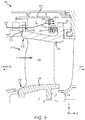
- high pressure turbine 154 may include a flow guide 207.
- Flow guide 207 may be configured to direct a cooling airflow along the outer diameter of high pressure turbine 154.
- flow guide 207 and OD stator vane rail 212 may define a secondary airflow path 209 to allow cooling air to flow through high pressure turbine 154 and cool OD engine components (such as, for example, an OD BOAS).
- Flow guide 207 and OD stator vane rail 212 may define a plenum D.
- the cooling air may flow through secondary airflow path 209 by passing through forward rail airflow aperture 218, through a vane support airflow aperture 208 in flow guide 207, and over OD aft rail 217.
- high pressure turbine 154 may include a thermally responsive flow meter 220 located proximate airflow aperture 208.
- Thermally responsive flow meter 220 may be coupled to a radially extending portion 211 of flow guide 207.
- Thermally responsive flow meter 220 may be configured to regulate air flow through airflow aperture 208.
- thermally responsive flow meter 220 may aid in metering the volume and/or flow rate of air entering secondary flow cavity E and being provided to downstream engine components.
- thermally responsive flow meter 220 may translate, for example, in a first circumferential direction, to allow an increased volume of cooling air to flow through airflow aperture 208.
- thermally responsive flow meter 220 may translate in a second, opposite circumferential direction to decrease the amount of cooling air flowing through airflow aperture 208.
- thermally responsive flow meter 220 may be installed and/or configured such that at the hottest engine operating conditions (e.g., take-off), when the greatest amount of cooling airflow is needed, an increased amount of air will flow through airflow aperture 208, and at cooler engine operating conditions (e.g., idle and cruise), when less cooling airflow is needed, less air will flow through airflow aperture 208.
- engine operating conditions e.g., take-off
- cooler engine operating conditions e.g., idle and cruise
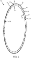
- Thermally responsive flow meter 220 may comprise a generally annular or "ring" shaped structure.
- Thermally responsive flow meter 220 may include a coil 221 and a plate 222 coupled to coil 221.
- Coil 221 and plate 222 may comprise any suitable material, such as, for example, a nickel-based alloy.
- Plate 222 includes an OD surface 223 and an ID surface 225.
- Plate 222 further includes opposing radially extending surfaces 226 and 227, which each extend between OD surface 223 and ID surface 225.
- a plurality of airflow apertures 224 may be formed through plate 222. Stated differently, plate 222 defines a plurality of airflow apertures 224.
- coil 221 may comprise a generally helical shape. In various embodiments, coil 221 may located circumferentially around the OD surface 223 of plate 222. A flange 228 may be located proximate a first end 229 of coil 221. Flange 228 may extend in a radially outward direction, or generally away from plate 222. In various embodiments, coil 221 may be located circumferentially about the ID surface 225 of plate 222, with flange 228 extending radially inward.
- thermally responsive flow meter 220 may be coupled to flow guide 207.
- Thermally responsive flow meter 220 may be configured to adjust the flow of cooling fluid through airflow apertures 208, in response to changes in engine operating temperatures.
- thermally responsive flow meter 220 may regulate airflow through airflow apertures 208 via thermal expansion and contraction of coil 221. For example, thermal expansion of coil 221 causes coil 221 and plate 222 to translate in a circumferential direction 240.
- Flow guide 207 may be configured to prevent or reduce thermal expansion of coil 221 and/or plate 222 in the radially outward and radially inward directions, thereby forcing coil 221 to translate in the circumferential direction.
- a radially inward facing surface 232 of flow guide 207 may be in contact with coil 221 and a radially outward facing surface 234 of flow guide 207 may be in contact with ID surface 225 of plate 222.
- Radially inward facing surface 232 of flow guide 207 may define a slot 230. Slot 230 may be configured to engage flange 228, thereby restricting movement of first end 229.
- thermally responsive flow meter 220 is illustrated in a covered position, in accordance with various embodiments.
- thermally responsive flow meter 220 may be installed and/or configured such that at the coolest engine operating conditions, the greatest area of airflow apertures 208 will be covered by plate 222.
- the greatest area of airflow apertures 208 may be covered, and/or airflow apertures 208 may be completely covered by plate 222, at lower power engine operating conditions, for example, in response to a temperature of the air along core flow-path C being less than approximately 800° F (427° C).
- approximately 800° F (427° C As used in the present context only, "approximately" means ⁇ 30°.
- thermally responsive flow meter 220 is illustrated in a partially covering position, in accordance with various embodiments.
- coil 221 may be configured such that as engine power and temperatures increase, coil 221 will thermally expand, thereby causing plate 222 to translate in circumferential direction 240. Translation of plate 222 may cause a greater area of airflow apertures 208 to be exposed. Stated differently, increases in operating temperatures may cause a greater area of airflow apertures 208 to be overlapped by airflow apertures 224, thereby allowing increased cooling flow through airflow apertures 208.
- coil 221 may be configured (e.g., a diameter of coil 221 may be selected) such that in response to the temperature of the air along core flow-path C increasing to greater than 800° F (427° C), the area of overlap between airflow apertures 224 and 208 will begin increasing.
- thermally responsive flow meter 220 is illustrated in a fully open position, in accordance with various embodiments.
- coil 221 and plate 222 may be configured to axially align airflow apertures 224 with airflow apertures 208, at take-off or other maximum or near maximum thrust and/or power conditions, such that a relatively larger amount of air flows through airflow apertures 208 than at other thrust conditions and is provided to downstream components.
- thermally responsive flow meter 220 may be configured to allow the greatest amount of cooling flow through airflow apertures 208, when a temperature of the air flowing along core flow-path C exceeds 1200° F (649° C).
- thermally responsive flow meter 220 may be configured to misalign airflow apertures 224 relative to airflow apertures 208 in response to a decrease in engine temperature.
- thermally responsive flow meter 300 may be located in airflow aperture 208. While thermally responsive flow meter 300 and thermally responsive flow meter 220 ( FIG. 2 ) are shown regulating airflow through airflow aperture 208 in high pressure turbine 154, it should be understand that thermally responsive flow meters of the present disclosure may be employed in other engine sections and components (e.g., in compressor section 124 and/or in lower pressure turbine 146) and/or with other airflow apertures.
- a thermally responsive flow meter may be coupled to OD forward rail 216 to regulate flow through forward rail airflow aperture 218.
- a thermally responsive flow meter may be disposed proximate ID stator vane rail 210, for example, at a first tangential onboard injector (TOBI), to regulate flow to ID engine components.
- TOBI first tangential onboard injector
- thermally responsive flow meter 300 may translate to allow an increased volume of cooling air to flow through airflow aperture 208. In response to decreases in the temperature of cooling air in secondary airflow path 209, thermally responsive flow meter 300 may translate to decrease the amount of cooling air flowing through airflow apertures 208.
- thermally responsive flow meter 300 may be installed and/or configured such that at the hottest engine operating conditions (e.g., take-off), when the greatest amount of cooling airflow is needed, a maximum or increased amount of air will flow through airflow apertures 208, and at cooler engine operating conditions (e.g., idle and cruise), when less cooling airflow is needed, less air will flow through airflow apertures 208.
- engine operating conditions e.g., take-off
- cooler engine operating conditions e.g., idle and cruise
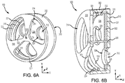
- Thermally responsive flow meter 300 may comprise a generally cylindrically shaped structure.
- Thermally responsive flow meter 300 may include a coil 321 and a plate 322 coupled to coil 321.
- Coil 321 and plate 322 may be disposed within a housing 302 of thermally responsive flow meter 300.
- Housing 302 may be configured to be press fit within airflow aperture 208, with momentary reference to FIG. 5 .
- Coil 321, plate 322, and housing 302 may comprise any suitable material, such as, for example, a nickel-based alloy.
- Housing 302 includes an inlet face 308 and an outlet face 310.
- An axle 320 may extend between inlet face 308 and outlet face 310.
- Plate 322 may be configured to rotate (i.e., translate circumferentially) about axle 320.
- a plurality of inlet airflow apertures 314 may be formed through inlet face 308.
- inlet face 308 e.g., surface 331
- inlet face 308 may define inlet airflow apertures 314.
- a plurality of outlet airflow apertures 312 may be formed through outlet face 310.
- outlet face 310 e.g., surface 323) may define outlet airflow apertures 312.
- a plurality of airflow apertures 324 may be formed through plate 322.
- plate 322 e.g., surface 325) defines a plurality of airflow apertures 324.
- Plate 322 includes opposing radially extending surfaces 326 and 327.
- Radially extending surface 327 may be oriented toward and located proximate outlet face 310 of housing 302.
- Radially extending surface 326 may be oriented toward inlet face 308 of housing 302.
- Coil 321 may be located over radially extending surface 326.
- coil 321 may be located between plate 322 and inlet face 308 of housing 302.
- Coil 321 may comprise a generally helical shape.
- Coil 321 may be configured to bias plate 322 toward and/or into contact with outlet face 310.
- a first end 332 of coil 321 may be coupled to plate 322.
- a second end 334 of coil 321 may be coupled to housing 302.
- thermally responsive flow meter 300 may be configured to adjust the flow of cooling fluid through airflow apertures 208, with momentary reference to FIG. 5 , in response to changes in temperature of air flowing along core flow-path C.
- thermally responsive flow meter 300 may regulate airflow through outlet airflow apertures 312 via thermal expansion and contraction of coil 321.
- thermal expansion of coil 321 may cause coil 321 and plate 322 to translate circumferentially about axle 320.
- housing 302 may be configured to prevent or reduce thermal expansion of coil 321 and/or plate 322 in the radially outward direction and axle 320 may prevent or reduce thermal expansion of coil 321 and/or plate 322 in the radially inward direction, thereby forcing coil 321 to translate in the circumferential direction.
- a radially inward facing surface 316 of housing 302 may be in contact with coil 321.
- Second end 334 of coil 321 may be coupled or otherwise fixed to housing 302, thereby restricting movement of second end 334.
- thermally responsive flow meter 300 is illustrated in a covered position, in accordance with various embodiments.
- thermally responsive flow meter 300 may be installed and/or configured such that the greatest area of outlet airflow apertures 312 will be covered by plate 322, at the coolest engine operating conditions.
- the greatest area of outlet airflow apertures 312 may be covered by plate 322, and/or outlet airflow apertures 312 may be completely covered by plate 322, at lower power engine operating conditions, for example, when air flowing along core flow-path C is less than approximately 800° F (427° C).
- “approximately” means ⁇ 30°.
- thermally responsive flow meter 300 is illustrated in a partially covered position, in accordance with various embodiments.
- coil 321 may be configured (e.g., a diameter of coil 321 is selected) such that as engine power and temperatures increase, for example, when a temperature of the air flowing along core flow-path C exceeds 800° F (427° C), coil 321 will thermally expand, thereby causing plate 322 to translate circumferentially about axle 320. Translation of plate 322 may cause a greater area of outlet airflow apertures 312 to be exposed.
- outlets airflow apertures 312 may be overlapped by airflow apertures 324 (i.e., a decreased area of outlet airflow apertures 312 is covered by plate 322), thereby allowing increased cooling flow through outlet airflow apertures 312 and airflow apertures 208, with momentary reference to FIG. 5 .
- thermally responsive flow meter 300 is illustrated in a fully open position, in accordance with various embodiments.
- the greatest amount of cooling airflow may be desirable.
- coil 321 and plate 322 may be configured to axially align airflow apertures 324 with outlet airflow apertures 312, at take-off or other maximum or near maximum thrust and/or power conditions, such that a relatively larger amount of air flows through outlet airflow apertures 312, and thus through airflow apertures 208, than at other thrust conditions.
- thermally responsive flow meter 300 may be configured to allow the greatest amount of cooling flow through outlet airflow apertures 312 and airflow apertures 208, when a temperature of the air flowing along core flow-path C exceeds 1200° F (649° C).
- thermally responsive flow meter 300 may be configured to misalign airflow apertures 324 relative to outlet airflow apertures 312 in response to a decrease in engine temperature. Decreasing the amount of air dedicated to cooling may increase the volume of air available for use in the engine core for power generation, which may increase engine and fuel efficiency.
- references to "various embodiments”, “one embodiment”, “an embodiment”, “an example embodiment”, etc. indicate that the embodiment described may include a particular feature, structure, or characteristic, but every embodiment may not necessarily include the particular feature, structure, or characteristic. Moreover, such phrases are not necessarily referring to the same embodiment. Further, when a particular feature, structure, or characteristic is described in connection with an embodiment, it is submitted that it is within the knowledge of one skilled in the art to affect such feature, structure, or characteristic in connection with other embodiments whether or not explicitly described. After reading the description, it will be apparent to one skilled in the relevant art(s) how to implement the disclosure in alternative embodiments.
Applications Claiming Priority (1)
| Application Number | Priority Date | Filing Date | Title |
|---|---|---|---|
| US16/004,687 US11248490B2 (en) | 2018-06-11 | 2018-06-11 | Thermally responsive cooling flow meters |
Publications (3)
| Publication Number | Publication Date |
|---|---|
| EP3584412A2 true EP3584412A2 (de) | 2019-12-25 |
| EP3584412A3 EP3584412A3 (de) | 2020-05-27 |
| EP3584412B1 EP3584412B1 (de) | 2021-11-10 |
Family
ID=66821061
Family Applications (1)
| Application Number | Title | Priority Date | Filing Date |
|---|---|---|---|
| EP19179398.3A Active EP3584412B1 (de) | 2018-06-11 | 2019-06-11 | Thermisch reagierende kühlungsdurchflussmesser für ein gasturbinentriebwerk |
Country Status (2)
| Country | Link |
|---|---|
| US (1) | US11248490B2 (de) |
| EP (1) | EP3584412B1 (de) |
Cited By (1)
| Publication number | Priority date | Publication date | Assignee | Title |
|---|---|---|---|---|
| EP4006309A1 (de) * | 2020-11-23 | 2022-06-01 | Raytheon Technologies Corporation | Keramischer gegenstand mit wärmeisolationsbuchse |
Families Citing this family (3)
| Publication number | Priority date | Publication date | Assignee | Title |
|---|---|---|---|---|
| US11492972B2 (en) * | 2019-12-30 | 2022-11-08 | General Electric Company | Differential alpha variable area metering |
| FR3106624B1 (fr) * | 2020-01-24 | 2022-02-18 | Safran Aircraft Engines | dispositif amélioré de détection d’anomalie de refroidissement pour turbomachine d’aéronef |
| US11434775B2 (en) * | 2020-08-31 | 2022-09-06 | Rolls-Royce North American Technologies Inc. | Turbine engine with metered cooling system |
Family Cites Families (18)
| Publication number | Priority date | Publication date | Assignee | Title |
|---|---|---|---|---|
| US3078671A (en) * | 1959-08-03 | 1963-02-26 | Houten Inc Van | Gas turbine power plant |
| US3440877A (en) | 1966-05-18 | 1969-04-29 | Rockwell Mfg Co | Temperature compensating apparatus for fluid flow meters |
| US4217755A (en) | 1978-12-04 | 1980-08-19 | General Motors Corporation | Cooling air control valve |
| US4487016A (en) | 1980-10-01 | 1984-12-11 | United Technologies Corporation | Modulated clearance control for an axial flow rotary machine |
| FR2604750B1 (fr) * | 1986-10-01 | 1988-12-02 | Snecma | Turbomachine munie d'un dispositif de commande automatique des debits de ventilation de turbine |
| US5263643A (en) | 1992-12-24 | 1993-11-23 | Therm-O-Disc, Incorporated | Thermally responsive relief valve |
| GB9510414D0 (en) | 1995-05-23 | 1995-07-19 | Aqua Thermal Controls Ltd | Device |
| GB2354290B (en) | 1999-09-18 | 2004-02-25 | Rolls Royce Plc | A cooling air flow control device for a gas turbine engine |
| US8186692B2 (en) * | 2009-03-17 | 2012-05-29 | Pratt & Whitney Canada Corp. | Split ring seal with spring element |
| US20140003920A1 (en) | 2012-07-02 | 2014-01-02 | United Technologies Corporation | Flow metering anti-rotation outer diameter (od) hex nut |
| US9327368B2 (en) * | 2012-09-27 | 2016-05-03 | United Technologies Corporation | Full ring inner air-seal with locking nut |
| US9261022B2 (en) | 2012-12-07 | 2016-02-16 | General Electric Company | System for controlling a cooling flow from a compressor section of a gas turbine |
| US9903274B2 (en) | 2014-11-07 | 2018-02-27 | General Electric Company | Variable geometry heat exchanger apparatus |
| US10113441B2 (en) | 2016-01-07 | 2018-10-30 | United Technologies Corporation | Thermally driven spring valve for turbine gas path parts |
| US20170234447A1 (en) | 2016-02-12 | 2017-08-17 | United Technologies Corporation | Methods and systems for modulating airflow |
| US20170350265A1 (en) | 2016-06-01 | 2017-12-07 | United Technologies Corporation | Flow metering and directing ring seal |
| US10563936B2 (en) | 2016-07-19 | 2020-02-18 | Unison Industries, Llc | Passive heat exchanger valve |
| US10352194B2 (en) * | 2017-08-30 | 2019-07-16 | United Technologies Corporation | Damper with adjustable seal |
-
2018
- 2018-06-11 US US16/004,687 patent/US11248490B2/en active Active
-
2019
- 2019-06-11 EP EP19179398.3A patent/EP3584412B1/de active Active
Cited By (2)
| Publication number | Priority date | Publication date | Assignee | Title |
|---|---|---|---|---|
| EP4006309A1 (de) * | 2020-11-23 | 2022-06-01 | Raytheon Technologies Corporation | Keramischer gegenstand mit wärmeisolationsbuchse |
| US11555451B2 (en) | 2020-11-23 | 2023-01-17 | Raytheon Technologies Corporation | Ceramic article with thermal insulation bushing |
Also Published As
| Publication number | Publication date |
|---|---|
| US20190376414A1 (en) | 2019-12-12 |
| EP3584412A3 (de) | 2020-05-27 |
| US11248490B2 (en) | 2022-02-15 |
| EP3584412B1 (de) | 2021-11-10 |
Similar Documents
| Publication | Publication Date | Title |
|---|---|---|
| EP3584412A2 (de) | Thermisch reagierende kühlungsdurchflussmesser | |
| US10557360B2 (en) | Vane intersegment gap sealing arrangement | |
| JP2016194293A (ja) | タービン排気フレーム及びベーン組み付け法 | |
| US11428241B2 (en) | System for an improved stator assembly | |
| US20170292532A1 (en) | Compressor secondary flow aft cone cooling scheme | |
| US11377957B2 (en) | Gas turbine engine with a diffuser cavity cooled compressor | |
| EP3404214B1 (de) | Schaufelspitzendichtungsanordnung und gasturbinentriebwerk mit einer solchen anordnung | |
| EP3388624A1 (de) | Schaufelblatt, triebwerksabschnitt und gasturbinentriebwerk | |
| EP3617458B1 (de) | Ringförmige dichtung eines gasturbinentriebwerks | |
| US20230116394A1 (en) | Tandem blade rotor disk | |
| US10393024B2 (en) | Multi-air stream cooling system | |
| EP3287603B1 (de) | Abgeschrägte leitschaufelschiene | |
| EP3412868A1 (de) | Plattformkühlung mit einstellbarer durchflussteilung für einen gasturbinenmotor | |
| EP3708782B1 (de) | Boas und verfahren zur herstellung von boas mit ermüdungsbeständigen kühleinlässen | |
| US11215056B2 (en) | Thermally isolated rotor systems and methods | |
| US10830048B2 (en) | Gas turbine rotor disk having scallop shield feature | |
| EP3647542B1 (de) | Zwischengekühlter tangentialer luftinjektor für gasturbinentriebwerke |
Legal Events
| Date | Code | Title | Description |
|---|---|---|---|
| PUAI | Public reference made under article 153(3) epc to a published international application that has entered the european phase |
Free format text: ORIGINAL CODE: 0009012 |
|
| STAA | Information on the status of an ep patent application or granted ep patent |
Free format text: STATUS: THE APPLICATION HAS BEEN PUBLISHED |
|
| AK | Designated contracting states |
Kind code of ref document: A2 Designated state(s): AL AT BE BG CH CY CZ DE DK EE ES FI FR GB GR HR HU IE IS IT LI LT LU LV MC MK MT NL NO PL PT RO RS SE SI SK SM TR |
|
| AX | Request for extension of the european patent |
Extension state: BA ME |
|
| PUAL | Search report despatched |
Free format text: ORIGINAL CODE: 0009013 |
|
| AK | Designated contracting states |
Kind code of ref document: A3 Designated state(s): AL AT BE BG CH CY CZ DE DK EE ES FI FR GB GR HR HU IE IS IT LI LT LU LV MC MK MT NL NO PL PT RO RS SE SI SK SM TR |
|
| AX | Request for extension of the european patent |
Extension state: BA ME |
|
| RIC1 | Information provided on ipc code assigned before grant |
Ipc: F02C 6/08 20060101ALI20200420BHEP Ipc: F02C 7/12 20060101ALI20200420BHEP Ipc: F01D 25/12 20060101ALI20200420BHEP Ipc: F02C 7/18 20060101ALN20200420BHEP Ipc: F01D 25/24 20060101ALN20200420BHEP Ipc: F01D 11/00 20060101ALN20200420BHEP Ipc: F01D 9/06 20060101AFI20200420BHEP Ipc: F01D 11/24 20060101ALI20200420BHEP |
|
| STAA | Information on the status of an ep patent application or granted ep patent |
Free format text: STATUS: REQUEST FOR EXAMINATION WAS MADE |
|
| 17P | Request for examination filed |
Effective date: 20201126 |
|
| RBV | Designated contracting states (corrected) |
Designated state(s): AL AT BE BG CH CY CZ DE DK EE ES FI FR GB GR HR HU IE IS IT LI LT LU LV MC MK MT NL NO PL PT RO RS SE SI SK SM TR |
|
| RAP1 | Party data changed (applicant data changed or rights of an application transferred) |
Owner name: RAYTHEON TECHNOLOGIES CORPORATION |
|
| RIC1 | Information provided on ipc code assigned before grant |
Ipc: F01D 9/06 20060101AFI20210422BHEP Ipc: F01D 11/24 20060101ALI20210422BHEP Ipc: F02C 7/12 20060101ALI20210422BHEP Ipc: F01D 25/12 20060101ALI20210422BHEP Ipc: F02C 6/08 20060101ALI20210422BHEP Ipc: F01D 11/00 20060101ALN20210422BHEP Ipc: F01D 25/24 20060101ALN20210422BHEP Ipc: F02C 7/18 20060101ALN20210422BHEP |
|
| GRAP | Despatch of communication of intention to grant a patent |
Free format text: ORIGINAL CODE: EPIDOSNIGR1 |
|
| STAA | Information on the status of an ep patent application or granted ep patent |
Free format text: STATUS: GRANT OF PATENT IS INTENDED |
|
| INTG | Intention to grant announced |
Effective date: 20210531 |
|
| GRAS | Grant fee paid |
Free format text: ORIGINAL CODE: EPIDOSNIGR3 |
|
| GRAA | (expected) grant |
Free format text: ORIGINAL CODE: 0009210 |
|
| STAA | Information on the status of an ep patent application or granted ep patent |
Free format text: STATUS: THE PATENT HAS BEEN GRANTED |
|
| AK | Designated contracting states |
Kind code of ref document: B1 Designated state(s): AL AT BE BG CH CY CZ DE DK EE ES FI FR GB GR HR HU IE IS IT LI LT LU LV MC MK MT NL NO PL PT RO RS SE SI SK SM TR |
|
| REG | Reference to a national code |
Ref country code: GB Ref legal event code: FG4D |
|
| REG | Reference to a national code |
Ref country code: AT Ref legal event code: REF Ref document number: 1446293 Country of ref document: AT Kind code of ref document: T Effective date: 20211115 Ref country code: CH Ref legal event code: EP |
|
| REG | Reference to a national code |
Ref country code: DE Ref legal event code: R096 Ref document number: 602019009092 Country of ref document: DE |
|
| REG | Reference to a national code |
Ref country code: IE Ref legal event code: FG4D |
|
| REG | Reference to a national code |
Ref country code: LT Ref legal event code: MG9D |
|
| REG | Reference to a national code |
Ref country code: NL Ref legal event code: MP Effective date: 20211110 |
|
| REG | Reference to a national code |
Ref country code: AT Ref legal event code: MK05 Ref document number: 1446293 Country of ref document: AT Kind code of ref document: T Effective date: 20211110 |
|
| PG25 | Lapsed in a contracting state [announced via postgrant information from national office to epo] |
Ref country code: RS Free format text: LAPSE BECAUSE OF FAILURE TO SUBMIT A TRANSLATION OF THE DESCRIPTION OR TO PAY THE FEE WITHIN THE PRESCRIBED TIME-LIMIT Effective date: 20211110 Ref country code: LT Free format text: LAPSE BECAUSE OF FAILURE TO SUBMIT A TRANSLATION OF THE DESCRIPTION OR TO PAY THE FEE WITHIN THE PRESCRIBED TIME-LIMIT Effective date: 20211110 Ref country code: FI Free format text: LAPSE BECAUSE OF FAILURE TO SUBMIT A TRANSLATION OF THE DESCRIPTION OR TO PAY THE FEE WITHIN THE PRESCRIBED TIME-LIMIT Effective date: 20211110 Ref country code: BG Free format text: LAPSE BECAUSE OF FAILURE TO SUBMIT A TRANSLATION OF THE DESCRIPTION OR TO PAY THE FEE WITHIN THE PRESCRIBED TIME-LIMIT Effective date: 20220210 Ref country code: AT Free format text: LAPSE BECAUSE OF FAILURE TO SUBMIT A TRANSLATION OF THE DESCRIPTION OR TO PAY THE FEE WITHIN THE PRESCRIBED TIME-LIMIT Effective date: 20211110 |
|
| PG25 | Lapsed in a contracting state [announced via postgrant information from national office to epo] |
Ref country code: IS Free format text: LAPSE BECAUSE OF FAILURE TO SUBMIT A TRANSLATION OF THE DESCRIPTION OR TO PAY THE FEE WITHIN THE PRESCRIBED TIME-LIMIT Effective date: 20220310 Ref country code: SE Free format text: LAPSE BECAUSE OF FAILURE TO SUBMIT A TRANSLATION OF THE DESCRIPTION OR TO PAY THE FEE WITHIN THE PRESCRIBED TIME-LIMIT Effective date: 20211110 Ref country code: PT Free format text: LAPSE BECAUSE OF FAILURE TO SUBMIT A TRANSLATION OF THE DESCRIPTION OR TO PAY THE FEE WITHIN THE PRESCRIBED TIME-LIMIT Effective date: 20220310 Ref country code: PL Free format text: LAPSE BECAUSE OF FAILURE TO SUBMIT A TRANSLATION OF THE DESCRIPTION OR TO PAY THE FEE WITHIN THE PRESCRIBED TIME-LIMIT Effective date: 20211110 Ref country code: NO Free format text: LAPSE BECAUSE OF FAILURE TO SUBMIT A TRANSLATION OF THE DESCRIPTION OR TO PAY THE FEE WITHIN THE PRESCRIBED TIME-LIMIT Effective date: 20220210 Ref country code: NL Free format text: LAPSE BECAUSE OF FAILURE TO SUBMIT A TRANSLATION OF THE DESCRIPTION OR TO PAY THE FEE WITHIN THE PRESCRIBED TIME-LIMIT Effective date: 20211110 Ref country code: LV Free format text: LAPSE BECAUSE OF FAILURE TO SUBMIT A TRANSLATION OF THE DESCRIPTION OR TO PAY THE FEE WITHIN THE PRESCRIBED TIME-LIMIT Effective date: 20211110 Ref country code: HR Free format text: LAPSE BECAUSE OF FAILURE TO SUBMIT A TRANSLATION OF THE DESCRIPTION OR TO PAY THE FEE WITHIN THE PRESCRIBED TIME-LIMIT Effective date: 20211110 Ref country code: GR Free format text: LAPSE BECAUSE OF FAILURE TO SUBMIT A TRANSLATION OF THE DESCRIPTION OR TO PAY THE FEE WITHIN THE PRESCRIBED TIME-LIMIT Effective date: 20220211 Ref country code: ES Free format text: LAPSE BECAUSE OF FAILURE TO SUBMIT A TRANSLATION OF THE DESCRIPTION OR TO PAY THE FEE WITHIN THE PRESCRIBED TIME-LIMIT Effective date: 20211110 |
|
| PG25 | Lapsed in a contracting state [announced via postgrant information from national office to epo] |
Ref country code: SM Free format text: LAPSE BECAUSE OF FAILURE TO SUBMIT A TRANSLATION OF THE DESCRIPTION OR TO PAY THE FEE WITHIN THE PRESCRIBED TIME-LIMIT Effective date: 20211110 Ref country code: SK Free format text: LAPSE BECAUSE OF FAILURE TO SUBMIT A TRANSLATION OF THE DESCRIPTION OR TO PAY THE FEE WITHIN THE PRESCRIBED TIME-LIMIT Effective date: 20211110 Ref country code: RO Free format text: LAPSE BECAUSE OF FAILURE TO SUBMIT A TRANSLATION OF THE DESCRIPTION OR TO PAY THE FEE WITHIN THE PRESCRIBED TIME-LIMIT Effective date: 20211110 Ref country code: EE Free format text: LAPSE BECAUSE OF FAILURE TO SUBMIT A TRANSLATION OF THE DESCRIPTION OR TO PAY THE FEE WITHIN THE PRESCRIBED TIME-LIMIT Effective date: 20211110 Ref country code: DK Free format text: LAPSE BECAUSE OF FAILURE TO SUBMIT A TRANSLATION OF THE DESCRIPTION OR TO PAY THE FEE WITHIN THE PRESCRIBED TIME-LIMIT Effective date: 20211110 Ref country code: CZ Free format text: LAPSE BECAUSE OF FAILURE TO SUBMIT A TRANSLATION OF THE DESCRIPTION OR TO PAY THE FEE WITHIN THE PRESCRIBED TIME-LIMIT Effective date: 20211110 |
|
| REG | Reference to a national code |
Ref country code: DE Ref legal event code: R097 Ref document number: 602019009092 Country of ref document: DE |
|
| PLBE | No opposition filed within time limit |
Free format text: ORIGINAL CODE: 0009261 |
|
| STAA | Information on the status of an ep patent application or granted ep patent |
Free format text: STATUS: NO OPPOSITION FILED WITHIN TIME LIMIT |
|
| 26N | No opposition filed |
Effective date: 20220811 |
|
| PG25 | Lapsed in a contracting state [announced via postgrant information from national office to epo] |
Ref country code: AL Free format text: LAPSE BECAUSE OF FAILURE TO SUBMIT A TRANSLATION OF THE DESCRIPTION OR TO PAY THE FEE WITHIN THE PRESCRIBED TIME-LIMIT Effective date: 20211110 |
|
| PG25 | Lapsed in a contracting state [announced via postgrant information from national office to epo] |
Ref country code: SI Free format text: LAPSE BECAUSE OF FAILURE TO SUBMIT A TRANSLATION OF THE DESCRIPTION OR TO PAY THE FEE WITHIN THE PRESCRIBED TIME-LIMIT Effective date: 20211110 |
|
| PG25 | Lapsed in a contracting state [announced via postgrant information from national office to epo] |
Ref country code: MC Free format text: LAPSE BECAUSE OF FAILURE TO SUBMIT A TRANSLATION OF THE DESCRIPTION OR TO PAY THE FEE WITHIN THE PRESCRIBED TIME-LIMIT Effective date: 20211110 |
|
| REG | Reference to a national code |
Ref country code: CH Ref legal event code: PL |
|
| REG | Reference to a national code |
Ref country code: BE Ref legal event code: MM Effective date: 20220630 |
|
| PG25 | Lapsed in a contracting state [announced via postgrant information from national office to epo] |
Ref country code: LU Free format text: LAPSE BECAUSE OF NON-PAYMENT OF DUE FEES Effective date: 20220611 Ref country code: LI Free format text: LAPSE BECAUSE OF NON-PAYMENT OF DUE FEES Effective date: 20220630 Ref country code: IE Free format text: LAPSE BECAUSE OF NON-PAYMENT OF DUE FEES Effective date: 20220611 Ref country code: CH Free format text: LAPSE BECAUSE OF NON-PAYMENT OF DUE FEES Effective date: 20220630 |
|
| PG25 | Lapsed in a contracting state [announced via postgrant information from national office to epo] |
Ref country code: IT Free format text: LAPSE BECAUSE OF FAILURE TO SUBMIT A TRANSLATION OF THE DESCRIPTION OR TO PAY THE FEE WITHIN THE PRESCRIBED TIME-LIMIT Effective date: 20211110 Ref country code: BE Free format text: LAPSE BECAUSE OF NON-PAYMENT OF DUE FEES Effective date: 20220630 |
|
| P01 | Opt-out of the competence of the unified patent court (upc) registered |
Effective date: 20230521 |
|
| PGFP | Annual fee paid to national office [announced via postgrant information from national office to epo] |
Ref country code: FR Payment date: 20230523 Year of fee payment: 5 Ref country code: DE Payment date: 20230523 Year of fee payment: 5 |
|
| PGFP | Annual fee paid to national office [announced via postgrant information from national office to epo] |
Ref country code: GB Payment date: 20230523 Year of fee payment: 5 |
|
| PG25 | Lapsed in a contracting state [announced via postgrant information from national office to epo] |
Ref country code: MK Free format text: LAPSE BECAUSE OF FAILURE TO SUBMIT A TRANSLATION OF THE DESCRIPTION OR TO PAY THE FEE WITHIN THE PRESCRIBED TIME-LIMIT Effective date: 20211110 Ref country code: CY Free format text: LAPSE BECAUSE OF FAILURE TO SUBMIT A TRANSLATION OF THE DESCRIPTION OR TO PAY THE FEE WITHIN THE PRESCRIBED TIME-LIMIT Effective date: 20211110 |