EP3584112A1 - Armrest - Google Patents
Armrest Download PDFInfo
- Publication number
- EP3584112A1 EP3584112A1 EP18178587.4A EP18178587A EP3584112A1 EP 3584112 A1 EP3584112 A1 EP 3584112A1 EP 18178587 A EP18178587 A EP 18178587A EP 3584112 A1 EP3584112 A1 EP 3584112A1
- Authority
- EP
- European Patent Office
- Prior art keywords
- armrest
- user interface
- beams
- pivot points
- distance
- Prior art date
- Legal status (The legal status is an assumption and is not a legal conclusion. Google has not performed a legal analysis and makes no representation as to the accuracy of the status listed.)
- Granted
Links
Images


Classifications
-
- B—PERFORMING OPERATIONS; TRANSPORTING
- B60—VEHICLES IN GENERAL
- B60N—SEATS SPECIALLY ADAPTED FOR VEHICLES; VEHICLE PASSENGER ACCOMMODATION NOT OTHERWISE PROVIDED FOR
- B60N2/00—Seats specially adapted for vehicles; Arrangement or mounting of seats in vehicles
- B60N2/75—Arm-rests
- B60N2/753—Arm-rests movable to an inoperative position
-
- B—PERFORMING OPERATIONS; TRANSPORTING
- B60—VEHICLES IN GENERAL
- B60N—SEATS SPECIALLY ADAPTED FOR VEHICLES; VEHICLE PASSENGER ACCOMMODATION NOT OTHERWISE PROVIDED FOR
- B60N2/00—Seats specially adapted for vehicles; Arrangement or mounting of seats in vehicles
- B60N2/75—Arm-rests
- B60N2/763—Arm-rests adjustable
- B60N2/767—Angle adjustment
-
- B—PERFORMING OPERATIONS; TRANSPORTING
- B60—VEHICLES IN GENERAL
- B60N—SEATS SPECIALLY ADAPTED FOR VEHICLES; VEHICLE PASSENGER ACCOMMODATION NOT OTHERWISE PROVIDED FOR
- B60N2/00—Seats specially adapted for vehicles; Arrangement or mounting of seats in vehicles
- B60N2/75—Arm-rests
- B60N2/763—Arm-rests adjustable
- B60N2/77—Height adjustment
-
- B—PERFORMING OPERATIONS; TRANSPORTING
- B60—VEHICLES IN GENERAL
- B60N—SEATS SPECIALLY ADAPTED FOR VEHICLES; VEHICLE PASSENGER ACCOMMODATION NOT OTHERWISE PROVIDED FOR
- B60N2/00—Seats specially adapted for vehicles; Arrangement or mounting of seats in vehicles
- B60N2/75—Arm-rests
- B60N2/79—Adaptations for additional use of the arm-rests
- B60N2/797—Adaptations for additional use of the arm-rests for use as electrical control means, e.g. switches
-
- B—PERFORMING OPERATIONS; TRANSPORTING
- B66—HOISTING; LIFTING; HAULING
- B66C—CRANES; LOAD-ENGAGING ELEMENTS OR DEVICES FOR CRANES, CAPSTANS, WINCHES, OR TACKLES
- B66C13/00—Other constructional features or details
- B66C13/52—Details of compartments for driving engines or motors or of operator's stands or cabins
- B66C13/54—Operator's stands or cabins
- B66C13/56—Arrangements of handles or pedals
-
- B—PERFORMING OPERATIONS; TRANSPORTING
- B66—HOISTING; LIFTING; HAULING
- B66F—HOISTING, LIFTING, HAULING OR PUSHING, NOT OTHERWISE PROVIDED FOR, e.g. DEVICES WHICH APPLY A LIFTING OR PUSHING FORCE DIRECTLY TO THE SURFACE OF A LOAD
- B66F9/00—Devices for lifting or lowering bulky or heavy goods for loading or unloading purposes
- B66F9/06—Devices for lifting or lowering bulky or heavy goods for loading or unloading purposes movable, with their loads, on wheels or the like, e.g. fork-lift trucks
- B66F9/075—Constructional features or details
- B66F9/0759—Details of operating station, e.g. seats, levers, operator platforms, cabin suspension
-
- E—FIXED CONSTRUCTIONS
- E02—HYDRAULIC ENGINEERING; FOUNDATIONS; SOIL SHIFTING
- E02F—DREDGING; SOIL-SHIFTING
- E02F9/00—Component parts of dredgers or soil-shifting machines, not restricted to one of the kinds covered by groups E02F3/00 - E02F7/00
- E02F9/20—Drives; Control devices
- E02F9/2004—Control mechanisms, e.g. control levers
Definitions
- the invention relates to an armrest, comprising an user interface.
- the armrest has to have a tilting structure in order to allow easier access on the seat or away from the seat.
- some utility vehicles have very small cabin, and for instance a back wall of the cabin may lie immediately back of the seat.
- a problem is that a joystick or some other user interface projecting from the armrest make easily contact with the back wall and limits the rotating angle of the armrest. This feature limits accessibility of the seat.
- an armrest comprising an user interface
- the armrest comprising an upper beam, a lower beam
- said upper and lower beams being arranged one on the other and attached at their first end rotatable with respect to an operator's operating environment by an upper and lower pivot points, respectively, the upper and lower pivot points having a first distance
- the upper and lower beams being attached at their second end rotatable to a user interface support by an upper and lower support pivot points, respectively, the upper and lower support pivot points having a second distance
- the beams and the pivot points being arranged so that due to rotation of the beams from an operating position of the armrest to an upper position of said armrest, the user interface support rotates less than the beams.
- the length of the upper beam is same as the length of the lower beam, and the first distance is same as the second distance, the beams and the pivot points thus making a parallelogram system, and said rotational movement of the user interface support is zero degree (0°).
- one of the upper and lower beams is shorten than the other beam.
- one of the first and second distances is shorten than the other distance.
- rotating axles of the pivot points are horizontally arranged.
- the lower pivot point is arranged closer to the user interface support as the upper pivot point.
- the operating position of the armrest is at least essentially horizontal position, and the upper position is at least essentially vertical position.
- the armrest comprises a locking means that is arranged to lock the armrest in at least one of the operating position and the upper position.
- the locking means of the armrest comprises a glide element arranged to glide in the upper or the lower beam, a locking stay, one end of which being connected rotatable to the glide element, and another end of the stay being arranged in the lower or the upper beam, respectively, the stay thus connecting the upper beam to the lower beam, and a locking mechanism that is arranged to prevent the glide element to glide when being in its locking state.
- the armrest comprises a height adjustment means that is arranged to change the height of the upper beam with respect to the operator's operating environment.
- the height adjustment means is arranged to tilt the upper beam, the tilting axle being in the upper pivot point.
- the height adjustment means comprises a screw lengthwise and rotatable arranged in the upper or the lower beam, a height adjustment stay comprising a first and a second end, the first end being connected rotatable to an adjustment element and comprising a threaded aperture, the screw being fitted through said aperture such that rotation of the screw moves the adjustment element in the upper or the lower beam, and the second end of the height adjustment stay being attached rotatable to the lower or the upper beam, respectively, thus the rotational movement of the screw being arranged to bring the beams closer to each other or, in opposite rotational direction, increasing distance of the beams.
- An advantage is that the height of the armrest may be controlled a precisely way.
- the user interface is connected to the user interface support by position adjustment means allowing movement between the user interface and the user interface support.
- At least an upper side of the upper beam comprises an armrest padding.
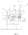
- Figure 1 is a schematic side view of an armrest arranged in a seat and being in its operating position an upper position
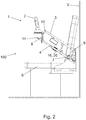
- Figure 2 is a schematic side view of the armrest shown in Figure 1 in an interstitial position
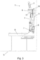
- Figure 3 is a schematic side view of the armrest shown in Figure 1 in an upper position
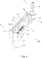
- Figure 4 is a schematic perspective view of the armrest shown in Figure 1 .
- the seat S of a vehicle V creates here an operator's operation environment, and the armrest 100 is attached to the seat S.
- An advantage of the combined structure of the seat S and the armrest 100 is that it may be designed fairly independently from other structures of vehicle.
- the operator may be e.g. driver of the vehicle, or a person taking care of some other functions than driving the vehicle, etc.
- the vehicle may be any type of a utility vehicle, such as a tractor, a truck, a farming machine, a forestry machine etc.
- the vehicle V is a mining vehicle or a construction vehicle. In mines and at other work sites different type of vehicles are used.
- the vehicles may be provided with one or more working devices for executing designed work tasks at the work site.
- the vehicle may be a wheel loader, a transport vehicle or dumper, a rock drilling rig, an excavator or a lifting machine, for example.
- the armrest 100 may be arranged in some another type of operation environment, such as a driving or controlling environment or cabin of a vehicle, where the driver or operator person is not sitting but in a standing position.
- the armrest 100 is attached to a door or a wall of a cabin.
- the armrest 100 includes a user interface 1 that comprises a joystick 2.
- the joystick 2 is operable in plurality of directions away from its central position.
- the joystick 2 may comprise one or more buttons or controllers.
- the user interface 1 may comprise further controllers, displays etc.
- the user interface 1 comprises a lever that is operable linearly in two directions.
- the mechanical structure of the armrest 100 comprises an upper beam 3 and a lower beam 4.
- the material of the beams may be e.g. metal, polymer or composite material.
- Preferably at least an upper side of the upper beam comprises an armrest padding 13.
- the upper and lower beams 3, 4 are arranged one on the other and attached at their first end 5 rotatable to the seat S by an upper 6 and lower 7 pivot points, respectively.
- the upper and lower pivot points 6, 7 are arranged in a first distance D1 from each other. Rotating axis of the pivot points 6, 7 are horizontally arranged.
- the rotating axis of the pivot points 6, 7 are arranged in a plane that deviates from a horizontal plane. Due to this feature, the movement of the armrest 100 from the operating position into the upper position may cause the armrest 100 also move laterally, e.g. away from the seat S. An advantage is that inconvenience caused by the armrest in its upper position may be limited. In another embodiment, the position of the pivot points 6, 7 causes the armrest 100 to move closer to e.g. the seat S. An advantage is that the armrest may reach its upper position even if the cabin's door or side wall is sloping inwards.
- the upper and lower beams 3, 4 are attached at their second end 8 rotatable to a user interface support 9 by an upper 10 and lower 11 support pivot points, respectively.
- the upper and lower support pivot points 10, 11 have a second distance D2.
- the upper beam 3 is connected to the user interface support 9 in two points, whereas the lower beam 4 is connected by one point only.
- This three-point attachment is sturdy and the one-point attachment of the lower beam 4 allows the user interface support 9 and/or the user interface 1 to extend laterally beyond contours of the lower beam without limiting rotational movement of the armrest 100.
- the pivot points 6, 7, 10, 11 have a simple structure, comprising an axle and an aperture therefor. In another embodiment, said pivot points 6, 7, 10, 11 comprises further a bearing that eases rotation of the beams.
- the lower pivot point 7 is arranged closer to the user interface support 9 as the upper pivot point 6. This way it has been created room for the beams 3, 4 for rotating in their upper position shown in Figure 3 .
- the operating position of the armrest 100 (shown in Figure 1 ) is at least essentially horizontal position.
- the term "at least essentially horizontal position” means range of angles ⁇ 15° to horizontal plane.
- the armrest 100 is arranged to slope down about 10°, e.g. 8° - 12° from the first end of beams towards the second ends of the beams.
- the upper position (shown in Figure 3 ) is at least essentially vertical position.
- the term "at least essentially vertical position” means range of angles ⁇ 20°, e.g. ⁇ 10° to vertical plane.
- the rotational movement of the armrest 100 is about 90°.
- the upper position may be more or less than the upper position shown in Figure 3 .
- the rotational movement between the operating position and the upper position may be more or less than 90°. According to an idea, the rotational movement is in range of 70° - 110°.
- the beams 3, 4 and the pivot points 6, 7, 10, 11 are arranged so that during rotation of the beams 3, 4 from an operating position of the armrest 100 shown in Figure 1 , to an upper position of said armrest shown in Figure 3 , the rotational movement of the user interface support 9 is smaller than the rotational movement of the beams 3, 4.
- the rotational movement of the user interface support 9 is about 0°, whereas the rotational movement of the beams 3, 4 is about 90°.
- the length of the upper beam 3 (i.e. distance D3 between the upper pivot point 6 and the upper support pivot point 10) is same as the length of the lower beam 4 (i.e. distance D4 between the lower pivot point 7 and the lower support pivot point 11).
- the first distance D1 is same as the second distance D2.
- the parallelogram system keeps the the user interface support 9 and the user interface 1 attached thereto in a constant position regardless of the rotational movement of the beams 3, 4. In other words, the rotational movement of the user interface support 9 is zero degree (0°), and the joystick 2 is always in a same upright position.
- the length of the upper beam 3 differs from the length of the lower beam 4 (i.e. distance D4).
- the upper beam 3 may be shorter or longer than the lower beam 4.
- the first distance D1 differs from the second distance D2.
- position of the user interface 1 in the upper position of the armrest 100 may fit optimally in dimensions and design of the cabin.
- position of the joystick 2 may be somewhat tilted forwards or backwards from the upright position shown in Figure 3 .
- the tilting of the armrest 100 may be assisted by an actuator, such as an electric motor or gas spring.
- the position of the user interface 1 is adjustable by position adjustment means 12 in relation to the user interface support 9.
- the user interface 1 may be rotated or swung, and/or its distance, lateral position and/or height position may be adjusted so that an ergonomically optimal position can be arranged.
- Figures 5a and 5b are schematic perspective views of a detail of the armrest shown in Figure 1 .
- the armrest 100 comprises a locking means 14 that is arranged to lock the armrest 100 in the operating position or the upper position, or to both of said positions.
- Figure 5a is showing a locked state of the locking means 14, and Figure 5b an open or unlocked state.
- the locking means 14 comprises a glide element 15 arranged to glide on rails in the upper beam 3.
- the locking means 14 further comprises a locking stay 16, one end of which being connected rotatable to the glide element 15, and another end being attached rotatable in the lower beam 4.
- the locking stay 16 thus connects the upper beam 3 to the lower beam 4.
- the locking stay 16 When the armrest 100 is in the operating position, the locking stay 16 is in an inclined position with respect to the beams 3, 4. As the armrest 100 is moved upwards, the distance between the beams 3, 4 begin first to grow and the locking stay 16 moves towards a perpendicular position in respect of the beams 3, 4. As the armrest 100 has reached about half-way of its rotational movement, the distance between the beams 3, 4 has a maximum value. As the rotational movement is continued, the distance begins to decrease.
- the locking means 14 further comprises a locking mechanism 17 that is arranged to prevent the glide element 15 to move when being in its locking state.
- the locking mechanism 17 comprises two pegs 23 arranged in the glide element 15 movable arranged and extending laterally from the glide element 15.
- the pegs 23 are connected to a control lever 24 through which the pegs can be moved into and out of receiving apertures 25 arranged in the upper beam 3.
- the pegs 23 inserted in the receiving apertures 25 lock the glide element 15 to the upper beam 3 and prevent movements of the armrest 100.
- An actuator (not shown), as a spring, may be arranged to urge the pegs 23 into their locked position.
- the pegs 23 has basically a round shape, but one of the pegs 23 comprises a flat or wedge-like section that facilitates alignment of the pegs 23 and the receiving apertures 25.
- the locking means 14 and the locking mechanism 17 may be realized several ways.
- the mechanism may be totally mechanical one, or alternatively, it may comprise electrical components such as a solenoid or an electric lock.
- the mechanism may even be a remote-controlled one.
- the structure of the locking means 14 may be reverse to that shown in Figures 5a, 5b , i.e. the glide element 15 may be arranged in the lower beam 4.
- Figure 6 is a schematic perspective view of another detail of the armrest shown in Figure 1 .
- the armrest 100 may comprise a height adjustment means 18 that is arranged to change the height of the upper beam 3 with respect to the operator's site, such as the seat S.
- the height adjustment means 18 is arranged to tilt the upper beam 3, the tilting axle being in the upper pivot point 6.
- the upper beam 3 raises or descends the most at its front part, i.e. close to the user interface 1.
- the height adjustment is realized by a mechanism that comprises a screw 19 that is lengthwise and rotatable arranged in the lower beam 4, and a height adjustment stay 20, a first end of which is connected rotatable to an adjustment element 21.
- the adjustment element 21 comprises a threaded aperture, through which the screw 19 is fitted. Thus position of the adjustment element 21 may be changed by rotating the screw 19.
- the second end of the height adjustment stay 20 is attached rotatable to the upper beam 3.
- the rotational movement of the screw 19 brings the beams 3, 4 closer to each other or, in opposite rotational direction of the screw 19, increases distance of the beams 3, 4.
- the height adjustment stay 20 and the locking stay 16 are a very same element. In some another embodiments, they may be separate elements.
- the locking mechanism and the height adjustment mechanism are separated so that the adjusted height of the armrest 100 is not affected or altered by tilting the armrest in its upper position.
- the structure of the height adjustment means 18 may be reverse to that shown in Figure 6 , i.e. the screw 19 may be arranged in the upper beam 3.
- a handle 22 may be connected to the screw 19 in order to ease of rotating the screw 19.
- the height adjustment means 18 is provided with an assistant means, such as electric motor, that eases the height adjustment.
- the electric motor may be arranged to rotate the screw 19.
- the height adjustment means 18 comprises an actuator, such as a gas spring, arranged between the upper and the lower beams 3, 4. Said actuator may even replace the height adjustment stay 20.
- the screw 19 is replaced by an actuator, such as a gas spring, that is arranged to move the height adjustment stay 20.
- the height adjustment means 18 may comprise a locking means that prevents unintentional movements of the armrest 100.
Landscapes
- Engineering & Computer Science (AREA)
- Mechanical Engineering (AREA)
- Transportation (AREA)
- Aviation & Aerospace Engineering (AREA)
- Structural Engineering (AREA)
- Civil Engineering (AREA)
- Mining & Mineral Resources (AREA)
- General Engineering & Computer Science (AREA)
- Life Sciences & Earth Sciences (AREA)
- Geology (AREA)
- Seats For Vehicles (AREA)
- Mechanical Control Devices (AREA)
Abstract
Description
- The invention relates to an armrest, comprising an user interface.
- It is known solution in modern utility vehicles to arrange an user interface, such as a joystick, in an armrest of user's or driver's seat. This solution may provide an ergonomically advantageous position.
- Typically the armrest has to have a tilting structure in order to allow easier access on the seat or away from the seat. However, some utility vehicles have very small cabin, and for instance a back wall of the cabin may lie immediately back of the seat. A problem is that a joystick or some other user interface projecting from the armrest make easily contact with the back wall and limits the rotating angle of the armrest. This feature limits accessibility of the seat.
- Viewed from a first aspect, there can be provided an armrest, comprising an user interface, the armrest comprising an upper beam, a lower beam, said upper and lower beams being arranged one on the other and attached at their first end rotatable with respect to an operator's operating environment by an upper and lower pivot points, respectively, the upper and lower pivot points having a first distance, the upper and lower beams being attached at their second end rotatable to a user interface support by an upper and lower support pivot points, respectively, the upper and lower support pivot points having a second distance, the beams and the pivot points being arranged so that due to rotation of the beams from an operating position of the armrest to an upper position of said armrest, the user interface support rotates less than the beams.
- Thereby an armrest the rotational movement of which is large and which allows an easy accessibility of the seat may be achieved.
- The arrangement and the method are characterised by what is stated in the characterising parts of the independent claims. Some other embodiments are characterised by what is stated in the other claims. Inventive embodiments are also disclosed in the specification and drawings of this patent application. The inventive content of the patent application may also be defined in other ways than defined in the following claims. The inventive content may also be formed of several separate inventions, especially if the invention is examined in the light of expressed or implicit sub-tasks or in view of obtained benefits or benefit groups. Some of the definitions contained in the following claims may then be unnecessary in view of the separate inventive ideas. Features of the different embodiments of the invention may, within the scope of the basic inventive idea, be applied to other embodiments.
- In one embodiment, the length of the upper beam is same as the length of the lower beam, and the first distance is same as the second distance, the beams and the pivot points thus making a parallelogram system, and said rotational movement of the user interface support is zero degree (0°). An advantage is that the user interface does not change its position during the tilting of the armrest.
- In one embodiment, one of the upper and lower beams is shorten than the other beam. An advantage is that it is possible to adapt the position of the user interface in the upper position of the armrest optimally in dimensions and design of the cabin.
- In one embodiment, one of the first and second distances is shorten than the other distance. An advantage is that it is possible to adapt the position of the user interface in the upper position of the armrest optimally in dimensions and design of the cabin.
- In one embodiment, rotating axles of the pivot points are horizontally arranged. An advantage is that the movement of the armrest takes place in a vertical plane, and thus there are no lateral movements that could be problematic in a small cabin.
- In one embodiment, the lower pivot point is arranged closer to the user interface support as the upper pivot point. An advantage is that it is possible to rotate the beams in upright position.
- In one embodiment, the operating position of the armrest is at least essentially horizontal position, and the upper position is at least essentially vertical position. An advantage is that this arrangement is an optimal one for at least most of operator's operating environments, such as seats.
- In one embodiment, the armrest comprises a locking means that is arranged to lock the armrest in at least one of the operating position and the upper position. An advantage is that the locked position does not change unintentionally.
- In one embodiment, the locking means of the armrest comprises a glide element arranged to glide in the upper or the lower beam, a locking stay, one end of which being connected rotatable to the glide element, and another end of the stay being arranged in the lower or the upper beam, respectively, the stay thus connecting the upper beam to the lower beam, and a locking mechanism that is arranged to prevent the glide element to glide when being in its locking state. An advantage is a simple and reliable realization of the locking means.
- In one embodiment, the armrest comprises a height adjustment means that is arranged to change the height of the upper beam with respect to the operator's operating environment. An advantage is that ergonomic of the operating environment may be optimized.
- In one embodiment, the height adjustment means is arranged to tilt the upper beam, the tilting axle being in the upper pivot point. An advantage is a simple and reliable structure.
- In one embodiment, the height adjustment means comprises a screw lengthwise and rotatable arranged in the upper or the lower beam, a height adjustment stay comprising a first and a second end, the first end being connected rotatable to an adjustment element and comprising a threaded aperture, the screw being fitted through said aperture such that rotation of the screw moves the adjustment element in the upper or the lower beam, and the second end of the height adjustment stay being attached rotatable to the lower or the upper beam, respectively, thus the rotational movement of the screw being arranged to bring the beams closer to each other or, in opposite rotational direction, increasing distance of the beams. An advantage is that the height of the armrest may be controlled a precisely way.
- In one embodiment, the user interface is connected to the user interface support by position adjustment means allowing movement between the user interface and the user interface support. An advantage is that ergonomic of the user interface may be optimized.
- In one embodiment, at least an upper side of the upper beam comprises an armrest padding. An advantage is that comfort of the armrest may be improved.
- Some embodiments illustrating the present disclosure are described in more detail in the attached drawings, in which
-
Figure 1 is a schematic side view of an armrest arranged in a seat and being in its operating position, -
Figure 2 is a schematic side view of the armrest shown inFigure 1 in an interstitial position, -
Figure 3 is a schematic side view of the armrest shown inFigure 1 in an upper position, -
Figure 4 is a schematic perspective view of the armrest shown inFigure 1 , -
Figures 5a and 5b are schematic perspective views of a detail of the armrest shown inFigure 1 , and -
Figure 6 is a schematic perspective view of another detail of the armrest shown inFigure 1 . - In the figures, some embodiments are shown simplified for the sake of clarity. Similar parts are marked with the same reference numbers in the figures.
-
Figure 1 is a schematic side view of an armrest arranged in a seat and being in its operating position an upper position,Figure 2 is a schematic side view of the armrest shown inFigure 1 in an interstitial position,Figure 3 is a schematic side view of the armrest shown inFigure 1 in an upper position, andFigure 4 is a schematic perspective view of the armrest shown inFigure 1 . - The seat S of a vehicle V creates here an operator's operation environment, and the
armrest 100 is attached to the seat S. An advantage of the combined structure of the seat S and thearmrest 100 is that it may be designed fairly independently from other structures of vehicle. - The operator may be e.g. driver of the vehicle, or a person taking care of some other functions than driving the vehicle, etc.
- The vehicle may be any type of a utility vehicle, such as a tractor, a truck, a farming machine, a forestry machine etc.. According to an idea, the vehicle V is a mining vehicle or a construction vehicle. In mines and at other work sites different type of vehicles are used. The vehicles may be provided with one or more working devices for executing designed work tasks at the work site. The vehicle may be a wheel loader, a transport vehicle or dumper, a rock drilling rig, an excavator or a lifting machine, for example.
- It is to be noted that instead of a seat, the
armrest 100 may be arranged in some another type of operation environment, such as a driving or controlling environment or cabin of a vehicle, where the driver or operator person is not sitting but in a standing position. In an embodiment, thearmrest 100 is attached to a door or a wall of a cabin.
Thearmrest 100 includes auser interface 1 that comprises ajoystick 2. Thejoystick 2 is operable in plurality of directions away from its central position. Furthermore, thejoystick 2 may comprise one or more buttons or controllers. - It is to be noted, that in addition to the
joystick 2, theuser interface 1 may comprise further controllers, displays etc. - In another embodiment, the
user interface 1 comprises a lever that is operable linearly in two directions. - The mechanical structure of the
armrest 100 comprises anupper beam 3 and alower beam 4. The material of the beams may be e.g. metal, polymer or composite material. Preferably at least an upper side of the upper beam comprises anarmrest padding 13. - The upper and
lower beams first end 5 rotatable to the seat S by an upper 6 and lower 7 pivot points, respectively. The upper andlower pivot points - It is to be noted, however, that in another embodiment, the rotating axis of the pivot points 6, 7 are arranged in a plane that deviates from a horizontal plane. Due to this feature, the movement of the
armrest 100 from the operating position into the upper position may cause thearmrest 100 also move laterally, e.g. away from the seat S. An advantage is that inconvenience caused by the armrest in its upper position may be limited. In another embodiment, the position of the pivot points 6, 7 causes thearmrest 100 to move closer to e.g. the seat S. An advantage is that the armrest may reach its upper position even if the cabin's door or side wall is sloping inwards. The upper andlower beams second end 8 rotatable to auser interface support 9 by an upper 10 and lower 11 support pivot points, respectively. The upper and lower support pivot points 10, 11 have a second distance D2. - In the embodiment shown in Figures, the
upper beam 3 is connected to theuser interface support 9 in two points, whereas thelower beam 4 is connected by one point only. This three-point attachment is sturdy and the one-point attachment of thelower beam 4 allows theuser interface support 9 and/or theuser interface 1 to extend laterally beyond contours of the lower beam without limiting rotational movement of thearmrest 100. - In an embodiment, the pivot points 6, 7, 10, 11 have a simple structure, comprising an axle and an aperture therefor. In another embodiment, said pivot points 6, 7, 10, 11 comprises further a bearing that eases rotation of the beams.
- In the embodiment shown in
Figures 1 - 4 , thelower pivot point 7 is arranged closer to theuser interface support 9 as theupper pivot point 6. This way it has been created room for thebeams Figure 3 . - In the embodiment shown in
Figures 1 - 4 , the operating position of the armrest 100 (shown inFigure 1 ) is at least essentially horizontal position. According to an idea, the term "at least essentially horizontal position" means range of angles ±15° to horizontal plane. In an embodiment, thearmrest 100 is arranged to slope down about 10°, e.g. 8° - 12° from the first end of beams towards the second ends of the beams. - The upper position (shown in
Figure 3 ) is at least essentially vertical position. According to an idea, the term "at least essentially vertical position" means range of angles ±20°, e.g. ± 10° to vertical plane. - In the embodiment shown in Figures, the rotational movement of the
armrest 100 is about 90°. In another embodiments, the upper position may be more or less than the upper position shown inFigure 3 . Also the rotational movement between the operating position and the upper position may be more or less than 90°. According to an idea, the rotational movement is in range of 70° - 110°. - The
beams beams armrest 100 shown inFigure 1 , to an upper position of said armrest shown inFigure 3 , the rotational movement of theuser interface support 9 is smaller than the rotational movement of thebeams user interface support 9 is about 0°, whereas the rotational movement of thebeams - In the embodiment shown in
Figures 1 - 4 , the length of the upper beam 3 (i.e. distance D3 between theupper pivot point 6 and the upper support pivot point 10) is same as the length of the lower beam 4 (i.e. distance D4 between thelower pivot point 7 and the lower support pivot point 11). Furthermore, the first distance D1 is same as the second distance D2. Thus thebeams user interface support 9 and theuser interface 1 attached thereto in a constant position regardless of the rotational movement of thebeams user interface support 9 is zero degree (0°), and thejoystick 2 is always in a same upright position. - In another embodiment, the length of the upper beam 3 (i.e. distance D3) differs from the length of the lower beam 4 (i.e. distance D4). The
upper beam 3 may be shorter or longer than thelower beam 4. In still another embodiment, the first distance D1 differs from the second distance D2. By varying said distances D1 - D4 it is possible to alter the rotational movement of theuser interface support 9. In other words, said rotational movement may differ from zero degree (0°). According to an idea, the rotational movement of theuser interface support 9 is in range of -20° - 20°, wherein minus degree means theuser interface support 9 is rotating in opposite direction compared to thebeams user interface 1 in the upper position of thearmrest 100 to fit optimally in dimensions and design of the cabin. For instance, position of thejoystick 2 may be somewhat tilted forwards or backwards from the upright position shown inFigure 3 . - Anyway, the rotational movement of the
user interface 1 is still smaller than the rotational movement of thebeams - The tilting of the
armrest 100 may be assisted by an actuator, such as an electric motor or gas spring. - In an embodiment, the position of the
user interface 1 is adjustable by position adjustment means 12 in relation to theuser interface support 9. Theuser interface 1 may be rotated or swung, and/or its distance, lateral position and/or height position may be adjusted so that an ergonomically optimal position can be arranged. -
Figures 5a and 5b are schematic perspective views of a detail of the armrest shown inFigure 1 . According to an idea, thearmrest 100 comprises a locking means 14 that is arranged to lock thearmrest 100 in the operating position or the upper position, or to both of said positions.Figure 5a is showing a locked state of the locking means 14, andFigure 5b an open or unlocked state. - In the embodiment shown in
Figures 5a, 5b , the locking means 14 comprises aglide element 15 arranged to glide on rails in theupper beam 3. - The locking means 14 further comprises a locking stay 16, one end of which being connected rotatable to the
glide element 15, and another end being attached rotatable in thelower beam 4. The locking stay 16 thus connects theupper beam 3 to thelower beam 4. - When the
armrest 100 is in the operating position, the locking stay 16 is in an inclined position with respect to thebeams armrest 100 is moved upwards, the distance between thebeams beams armrest 100 has reached about half-way of its rotational movement, the distance between thebeams - The locking means 14 further comprises a
locking mechanism 17 that is arranged to prevent theglide element 15 to move when being in its locking state. - In the embodiment shown in
Figures 5a, 5b , thelocking mechanism 17 comprises twopegs 23 arranged in theglide element 15 movable arranged and extending laterally from theglide element 15. Thepegs 23 are connected to acontrol lever 24 through which the pegs can be moved into and out of receivingapertures 25 arranged in theupper beam 3. Thepegs 23 inserted in the receivingapertures 25 lock theglide element 15 to theupper beam 3 and prevent movements of thearmrest 100. An actuator (not shown), as a spring, may be arranged to urge thepegs 23 into their locked position. - In the shown embodiment, the
pegs 23 has basically a round shape, but one of thepegs 23 comprises a flat or wedge-like section that facilitates alignment of thepegs 23 and the receivingapertures 25. - However, it is to be noted that the locking means 14 and the
locking mechanism 17 may be realized several ways. The mechanism may be totally mechanical one, or alternatively, it may comprise electrical components such as a solenoid or an electric lock. The mechanism may even be a remote-controlled one. - It is to be noted, that the structure of the locking means 14 may be reverse to that shown in
Figures 5a, 5b , i.e. theglide element 15 may be arranged in thelower beam 4. -
Figure 6 is a schematic perspective view of another detail of the armrest shown inFigure 1 . According to an idea, thearmrest 100 may comprise a height adjustment means 18 that is arranged to change the height of theupper beam 3 with respect to the operator's site, such as the seat S. - In the embodiment shown in
Figure 6 , the height adjustment means 18 is arranged to tilt theupper beam 3, the tilting axle being in theupper pivot point 6. Thus theupper beam 3 raises or descends the most at its front part, i.e. close to theuser interface 1. - The height adjustment is realized by a mechanism that comprises a
screw 19 that is lengthwise and rotatable arranged in thelower beam 4, and a height adjustment stay 20, a first end of which is connected rotatable to anadjustment element 21. Theadjustment element 21 comprises a threaded aperture, through which thescrew 19 is fitted. Thus position of theadjustment element 21 may be changed by rotating thescrew 19. - The second end of the height adjustment stay 20 is attached rotatable to the
upper beam 3. The rotational movement of thescrew 19 brings thebeams screw 19, increases distance of thebeams - In the embodiment shown in Figures, the height adjustment stay 20 and the locking stay 16 are a very same element. In some another embodiments, they may be separate elements.
- According to an idea, the locking mechanism and the height adjustment mechanism are separated so that the adjusted height of the
armrest 100 is not affected or altered by tilting the armrest in its upper position. - It is to be noted, that the structure of the height adjustment means 18 may be reverse to that shown in
Figure 6 , i.e. thescrew 19 may be arranged in theupper beam 3. - A
handle 22 may be connected to thescrew 19 in order to ease of rotating thescrew 19. - In an embodiment, the height adjustment means 18 is provided with an assistant means, such as electric motor, that eases the height adjustment. For instance, the electric motor may be arranged to rotate the
screw 19. - In another embodiment, the height adjustment means 18 comprises an actuator, such as a gas spring, arranged between the upper and the
lower beams - In still another embodiment, the
screw 19 is replaced by an actuator, such as a gas spring, that is arranged to move the height adjustment stay 20. - The height adjustment means 18 may comprise a locking means that prevents unintentional movements of the
armrest 100. - The invention is not limited solely to the embodiments described above, but instead many variations are possible within the scope of the inventive concept defined by the claims below. Within the scope of the inventive concept the attributes of different embodiments and applications can be used in conjunction with or replace the attributes of another embodiment or application.
- The drawings and the related description are only intended to illustrate the idea of the invention. The invention may vary in detail within the scope of the inventive idea defined in the following claims.
-
- 1
- user interface
- 2
- joystick
- 3
- upper beam
- 4
- lower beam
- 5
- first end of beams
- 6
- upper pivot point
- 7
- lower pivot point
- 8
- second end of beams
- 9
- user interface support
- 10
- upper support pivot point
- 11
- lower support pivot point
- 12
- position adjustment means
- 13
- armrest padding
- 14
- locking means
- 15
- glide element
- 16
- locking stay
- 17
- locking mechanism
- 18
- height adjustment means
- 19
- screw
- 20
- height adjustment stay
- 21
- adjustment element
- 22
- handle
- 23
- peg
- 24
- control lever
- 25
- receiving aperture
- 100
- armrest
- D1
- first distance
- D2
- second distance
- D3
- third distance
- D4
- fourth distance
- S
- seat
- V
- vehicle
Claims (15)
- An armrest (100), comprising an user interface (1), the armrest comprising- an upper beam (3),- a lower beam (4),- said upper and lower beams being arranged one on the other and attached at their first end (5) rotatable with respect to an operator's operating environment by an upper and lower pivot points (6, 7), respectively, the upper and lower pivot points having a first distance (D1),- the upper and lower beams being attached at their second end (8) rotatable to a user interface support (9) by an upper and lower support pivot points (10, 11), respectively, the upper and lower support pivot points having a second distance (D2),- the beams (3, 4) and the pivot points (6, 7, 10 ,11) being arranged so that due to rotation of the beams (3, 4) from an operating position of the armrest (100) to an upper position of said armrest, the user interface support (9) rotates less than the beams (3, 4).
- The armrest as claimed in claim 1, wherein- the length of the upper beam (3) is same as the length of the lower beam (4), and wherein- the first distance (D1) is same as the second distance (D2), the beams and the pivot points thus making a parallelogram system, and- said rotational movement of the user interface support (9) is zero degree (0°).
- The armrest as claimed in claim 1, wherein one of the upper and lower beams (3, 4) is shorten than the other beam (3, 4).
- The armrest as claimed in claim 1, wherein one of the first and second distances (D1,D2) is shorten than the other distance (D1, D2).
- The armrest as claimed in claim 1 or 2, wherein rotating axles of the pivot points (6, 7, 10, 11) are horizontally arranged.
- The armrest as claimed in any of the preceding claims, wherein the lower pivot point (7) is arranged closer to the user interface support (9) as the upper pivot point (6) .
- The armrest as claimed in any of the preceding claims, wherein- the operating position of the armrest (100) is at least essentially horizontal position, and- the upper position is at least essentially vertical position.
- The armrest as claimed in any of the preceding claims, comprising- a locking means (14) that is arranged to lock the armrest (100) in at least one of the operating position and the upper position.
- The armrest as claimed in claim 8, wherein said locking means (14) comprises- a glide element (15) arranged to glide in the upper or the lower beam (3, 4),- a locking stay (16), one end of which being connected rotatable to the glide element (15), and- another end of the locking stay (16) being arranged in the lower or the upper beam (4, 3), respectively,- the locking stay (16) thus connecting the upper beam (3) to the lower beam (4), and- a locking mechanism (17) that, when being in its locking state, is arranged to prevent the glide element (15) to glide.
- The armrest as claimed in any of the preceding claims, comprising a height adjustment means (18) that is arranged to change the height of the upper beam (3) with respect to the operator's operating environment.
- The armrest as claimed in claim 10, wherein the height adjustment means (18) is arranged to tilt the upper beam (3), the tilting axle being in the upper pivot point (6).
- The armrest as claimed in claim 11, wherein the height adjustment means (18) comprises- a screw (19) lengthwise and rotatable arranged in the upper or the lower beam (3, 4),- a height adjustment stay (20) comprising a first and a second end, the first end being connected rotatable to an adjustment element (21) and comprising a threaded aperture, the screw being fitted through said aperture such that rotation of the screw (19) moves the adjustment element (21) in the upper or the lower beam (3, 4), and- the second end of the height adjustment stay (20) being attached rotatable to the other beam (3, 4), thus the rotational movement of the screw (19) being arranged to bring the beams (3, 4) closer to each other or, in opposite rotational direction, increasing distance of the beams (3, 4).
- The armrest as claimed in any of the preceding claims, wherein the user interface (1) comprises a lever, such as a joystick (2).
- The armrest as claimed in any of the preceding claims, wherein the user interface (1) is connected to the user interface support (9) by position adjustment means (12) allowing movement between the user interface (1) and the user interface support (9).
- The armrest as claimed in any of the preceding claims, wherein at least an upper side of the upper beam (3) comprises an armrest padding.
Priority Applications (2)
| Application Number | Priority Date | Filing Date | Title |
|---|---|---|---|
| EP18178587.4A EP3584112B1 (en) | 2018-06-19 | 2018-06-19 | Armrest |
| PCT/EP2019/062351 WO2019242941A1 (en) | 2018-06-19 | 2019-05-14 | Armrest |
Applications Claiming Priority (1)
| Application Number | Priority Date | Filing Date | Title |
|---|---|---|---|
| EP18178587.4A EP3584112B1 (en) | 2018-06-19 | 2018-06-19 | Armrest |
Publications (2)
| Publication Number | Publication Date |
|---|---|
| EP3584112A1 true EP3584112A1 (en) | 2019-12-25 |
| EP3584112B1 EP3584112B1 (en) | 2021-10-13 |
Family
ID=62784005
Family Applications (1)
| Application Number | Title | Priority Date | Filing Date |
|---|---|---|---|
| EP18178587.4A Active EP3584112B1 (en) | 2018-06-19 | 2018-06-19 | Armrest |
Country Status (2)
| Country | Link |
|---|---|
| EP (1) | EP3584112B1 (en) |
| WO (1) | WO2019242941A1 (en) |
Families Citing this family (2)
| Publication number | Priority date | Publication date | Assignee | Title |
|---|---|---|---|---|
| DE102020134877B4 (en) * | 2020-12-23 | 2026-05-07 | Grammer Aktiengesellschaft | Height-adjustable control lever bracket for a commercial vehicle seat |
| CN117656963A (en) * | 2022-08-31 | 2024-03-08 | 重庆安道拓汽车部件系统有限公司 | A kind of seat following armrest frame |
Citations (4)
| Publication number | Priority date | Publication date | Assignee | Title |
|---|---|---|---|---|
| EP0018662A1 (en) * | 1979-05-08 | 1980-11-12 | Uop Inc. | Multi-position armrest |
| US6164285A (en) * | 1998-03-16 | 2000-12-26 | Case Corporation | Position-adjustable control console |
| EP2369066A2 (en) * | 2010-03-26 | 2011-09-28 | BOMAG GmbH | Operator's station of a construction machine |
| EP2832583A2 (en) * | 2013-08-01 | 2015-02-04 | CLAAS Tractor SAS | Agricultural vehicle |
-
2018
- 2018-06-19 EP EP18178587.4A patent/EP3584112B1/en active Active
-
2019
- 2019-05-14 WO PCT/EP2019/062351 patent/WO2019242941A1/en not_active Ceased
Patent Citations (4)
| Publication number | Priority date | Publication date | Assignee | Title |
|---|---|---|---|---|
| EP0018662A1 (en) * | 1979-05-08 | 1980-11-12 | Uop Inc. | Multi-position armrest |
| US6164285A (en) * | 1998-03-16 | 2000-12-26 | Case Corporation | Position-adjustable control console |
| EP2369066A2 (en) * | 2010-03-26 | 2011-09-28 | BOMAG GmbH | Operator's station of a construction machine |
| EP2832583A2 (en) * | 2013-08-01 | 2015-02-04 | CLAAS Tractor SAS | Agricultural vehicle |
Also Published As
| Publication number | Publication date |
|---|---|
| EP3584112B1 (en) | 2021-10-13 |
| WO2019242941A1 (en) | 2019-12-26 |
Similar Documents
| Publication | Publication Date | Title |
|---|---|---|
| US7520567B2 (en) | Systems and methods for seat repositioning | |
| US7712571B2 (en) | Ergonomic machine control console | |
| EP1633595B1 (en) | Armrest for use with a vehicle seat | |
| US11068015B2 (en) | Variable track joystick devices and work vehicles containing the same | |
| EP0712062B1 (en) | Manually-actuated control device for an operator stand or seat | |
| KR102941561B1 (en) | Construction machinery | |
| AU2022200163B2 (en) | Control elements for materials handling vehicles | |
| EP3584112B1 (en) | Armrest | |
| US11383753B2 (en) | Traveling vehicle | |
| US20180217626A1 (en) | Control Device | |
| KR102271408B1 (en) | work vehicle | |
| US5038887A (en) | Control console for bidirectional service vehicle | |
| US20090174244A1 (en) | Seat height and tilt adjustment apparatus and method | |
| US4526204A (en) | Control apparatus for hydraulic valve | |
| KR20220117888A (en) | The tilt structure of the console | |
| DE102004052757A1 (en) | Working machine, in particular industrial truck | |
| EP3054367A2 (en) | Vehicle, in particular tracked vehicle for piste design and maintenance | |
| JPH08107709A (en) | Shelf work vehicle | |
| US20250043539A1 (en) | Offset control stick system and method | |
| JP2002339390A (en) | Work vehicle | |
| DE102024124356A1 (en) | Control element for a forklift truck with a handlebar and a vehicle-mounted console | |
| DE102024132002A1 (en) | Vehicle seat with adjustable console | |
| WO2022117485A2 (en) | Control unit for a mobile work machine, method for positioning an operating point of a mobile work machine, and mobile work machine | |
| JP2002339388A (en) | Work vehicle | |
| DE102005030329A1 (en) | Fork raising, lowering and tilting apparatus for forklift truck has bidirectional control lever that is initially set in neutral position, and can be inclined in left and right directions with respect to axis line of driver's seat |
Legal Events
| Date | Code | Title | Description |
|---|---|---|---|
| PUAI | Public reference made under article 153(3) epc to a published international application that has entered the european phase |
Free format text: ORIGINAL CODE: 0009012 |
|
| STAA | Information on the status of an ep patent application or granted ep patent |
Free format text: STATUS: THE APPLICATION HAS BEEN PUBLISHED |
|
| AK | Designated contracting states |
Kind code of ref document: A1 Designated state(s): AL AT BE BG CH CY CZ DE DK EE ES FI FR GB GR HR HU IE IS IT LI LT LU LV MC MK MT NL NO PL PT RO RS SE SI SK SM TR |
|
| AX | Request for extension of the european patent |
Extension state: BA ME |
|
| STAA | Information on the status of an ep patent application or granted ep patent |
Free format text: STATUS: REQUEST FOR EXAMINATION WAS MADE |
|
| 17P | Request for examination filed |
Effective date: 20200625 |
|
| RBV | Designated contracting states (corrected) |
Designated state(s): AL AT BE BG CH CY CZ DE DK EE ES FI FR GB GR HR HU IE IS IT LI LT LU LV MC MK MT NL NO PL PT RO RS SE SI SK SM TR |
|
| GRAP | Despatch of communication of intention to grant a patent |
Free format text: ORIGINAL CODE: EPIDOSNIGR1 |
|
| STAA | Information on the status of an ep patent application or granted ep patent |
Free format text: STATUS: GRANT OF PATENT IS INTENDED |
|
| INTG | Intention to grant announced |
Effective date: 20210723 |
|
| GRAS | Grant fee paid |
Free format text: ORIGINAL CODE: EPIDOSNIGR3 |
|
| GRAA | (expected) grant |
Free format text: ORIGINAL CODE: 0009210 |
|
| STAA | Information on the status of an ep patent application or granted ep patent |
Free format text: STATUS: THE PATENT HAS BEEN GRANTED |
|
| AK | Designated contracting states |
Kind code of ref document: B1 Designated state(s): AL AT BE BG CH CY CZ DE DK EE ES FI FR GB GR HR HU IE IS IT LI LT LU LV MC MK MT NL NO PL PT RO RS SE SI SK SM TR |
|
| REG | Reference to a national code |
Ref country code: GB Ref legal event code: FG4D |
|
| REG | Reference to a national code |
Ref country code: CH Ref legal event code: EP |
|
| REG | Reference to a national code |
Ref country code: DE Ref legal event code: R096 Ref document number: 602018024892 Country of ref document: DE |
|
| REG | Reference to a national code |
Ref country code: IE Ref legal event code: FG4D |
|
| REG | Reference to a national code |
Ref country code: AT Ref legal event code: REF Ref document number: 1437958 Country of ref document: AT Kind code of ref document: T Effective date: 20211115 |
|
| REG | Reference to a national code |
Ref country code: LT Ref legal event code: MG9D |
|
| REG | Reference to a national code |
Ref country code: NL Ref legal event code: MP Effective date: 20211013 |
|
| REG | Reference to a national code |
Ref country code: AT Ref legal event code: MK05 Ref document number: 1437958 Country of ref document: AT Kind code of ref document: T Effective date: 20211013 |
|
| PG25 | Lapsed in a contracting state [announced via postgrant information from national office to epo] |
Ref country code: RS Free format text: LAPSE BECAUSE OF FAILURE TO SUBMIT A TRANSLATION OF THE DESCRIPTION OR TO PAY THE FEE WITHIN THE PRESCRIBED TIME-LIMIT Effective date: 20211013 Ref country code: LT Free format text: LAPSE BECAUSE OF FAILURE TO SUBMIT A TRANSLATION OF THE DESCRIPTION OR TO PAY THE FEE WITHIN THE PRESCRIBED TIME-LIMIT Effective date: 20211013 Ref country code: FI Free format text: LAPSE BECAUSE OF FAILURE TO SUBMIT A TRANSLATION OF THE DESCRIPTION OR TO PAY THE FEE WITHIN THE PRESCRIBED TIME-LIMIT Effective date: 20211013 Ref country code: BG Free format text: LAPSE BECAUSE OF FAILURE TO SUBMIT A TRANSLATION OF THE DESCRIPTION OR TO PAY THE FEE WITHIN THE PRESCRIBED TIME-LIMIT Effective date: 20220113 Ref country code: AT Free format text: LAPSE BECAUSE OF FAILURE TO SUBMIT A TRANSLATION OF THE DESCRIPTION OR TO PAY THE FEE WITHIN THE PRESCRIBED TIME-LIMIT Effective date: 20211013 |
|
| PG25 | Lapsed in a contracting state [announced via postgrant information from national office to epo] |
Ref country code: IS Free format text: LAPSE BECAUSE OF FAILURE TO SUBMIT A TRANSLATION OF THE DESCRIPTION OR TO PAY THE FEE WITHIN THE PRESCRIBED TIME-LIMIT Effective date: 20220213 Ref country code: SE Free format text: LAPSE BECAUSE OF FAILURE TO SUBMIT A TRANSLATION OF THE DESCRIPTION OR TO PAY THE FEE WITHIN THE PRESCRIBED TIME-LIMIT Effective date: 20211013 Ref country code: PT Free format text: LAPSE BECAUSE OF FAILURE TO SUBMIT A TRANSLATION OF THE DESCRIPTION OR TO PAY THE FEE WITHIN THE PRESCRIBED TIME-LIMIT Effective date: 20220214 Ref country code: PL Free format text: LAPSE BECAUSE OF FAILURE TO SUBMIT A TRANSLATION OF THE DESCRIPTION OR TO PAY THE FEE WITHIN THE PRESCRIBED TIME-LIMIT Effective date: 20211013 Ref country code: NO Free format text: LAPSE BECAUSE OF FAILURE TO SUBMIT A TRANSLATION OF THE DESCRIPTION OR TO PAY THE FEE WITHIN THE PRESCRIBED TIME-LIMIT Effective date: 20220113 Ref country code: NL Free format text: LAPSE BECAUSE OF FAILURE TO SUBMIT A TRANSLATION OF THE DESCRIPTION OR TO PAY THE FEE WITHIN THE PRESCRIBED TIME-LIMIT Effective date: 20211013 Ref country code: LV Free format text: LAPSE BECAUSE OF FAILURE TO SUBMIT A TRANSLATION OF THE DESCRIPTION OR TO PAY THE FEE WITHIN THE PRESCRIBED TIME-LIMIT Effective date: 20211013 Ref country code: HR Free format text: LAPSE BECAUSE OF FAILURE TO SUBMIT A TRANSLATION OF THE DESCRIPTION OR TO PAY THE FEE WITHIN THE PRESCRIBED TIME-LIMIT Effective date: 20211013 Ref country code: GR Free format text: LAPSE BECAUSE OF FAILURE TO SUBMIT A TRANSLATION OF THE DESCRIPTION OR TO PAY THE FEE WITHIN THE PRESCRIBED TIME-LIMIT Effective date: 20220114 Ref country code: ES Free format text: LAPSE BECAUSE OF FAILURE TO SUBMIT A TRANSLATION OF THE DESCRIPTION OR TO PAY THE FEE WITHIN THE PRESCRIBED TIME-LIMIT Effective date: 20211013 |
|
| REG | Reference to a national code |
Ref country code: DE Ref legal event code: R097 Ref document number: 602018024892 Country of ref document: DE |
|
| PG25 | Lapsed in a contracting state [announced via postgrant information from national office to epo] |
Ref country code: SM Free format text: LAPSE BECAUSE OF FAILURE TO SUBMIT A TRANSLATION OF THE DESCRIPTION OR TO PAY THE FEE WITHIN THE PRESCRIBED TIME-LIMIT Effective date: 20211013 Ref country code: SK Free format text: LAPSE BECAUSE OF FAILURE TO SUBMIT A TRANSLATION OF THE DESCRIPTION OR TO PAY THE FEE WITHIN THE PRESCRIBED TIME-LIMIT Effective date: 20211013 Ref country code: RO Free format text: LAPSE BECAUSE OF FAILURE TO SUBMIT A TRANSLATION OF THE DESCRIPTION OR TO PAY THE FEE WITHIN THE PRESCRIBED TIME-LIMIT Effective date: 20211013 Ref country code: EE Free format text: LAPSE BECAUSE OF FAILURE TO SUBMIT A TRANSLATION OF THE DESCRIPTION OR TO PAY THE FEE WITHIN THE PRESCRIBED TIME-LIMIT Effective date: 20211013 Ref country code: DK Free format text: LAPSE BECAUSE OF FAILURE TO SUBMIT A TRANSLATION OF THE DESCRIPTION OR TO PAY THE FEE WITHIN THE PRESCRIBED TIME-LIMIT Effective date: 20211013 Ref country code: CZ Free format text: LAPSE BECAUSE OF FAILURE TO SUBMIT A TRANSLATION OF THE DESCRIPTION OR TO PAY THE FEE WITHIN THE PRESCRIBED TIME-LIMIT Effective date: 20211013 |
|
| PLBE | No opposition filed within time limit |
Free format text: ORIGINAL CODE: 0009261 |
|
| STAA | Information on the status of an ep patent application or granted ep patent |
Free format text: STATUS: NO OPPOSITION FILED WITHIN TIME LIMIT |
|
| 26N | No opposition filed |
Effective date: 20220714 |
|
| PG25 | Lapsed in a contracting state [announced via postgrant information from national office to epo] |
Ref country code: AL Free format text: LAPSE BECAUSE OF FAILURE TO SUBMIT A TRANSLATION OF THE DESCRIPTION OR TO PAY THE FEE WITHIN THE PRESCRIBED TIME-LIMIT Effective date: 20211013 |
|
| PG25 | Lapsed in a contracting state [announced via postgrant information from national office to epo] |
Ref country code: SI Free format text: LAPSE BECAUSE OF FAILURE TO SUBMIT A TRANSLATION OF THE DESCRIPTION OR TO PAY THE FEE WITHIN THE PRESCRIBED TIME-LIMIT Effective date: 20211013 |
|
| PG25 | Lapsed in a contracting state [announced via postgrant information from national office to epo] |
Ref country code: MC Free format text: LAPSE BECAUSE OF FAILURE TO SUBMIT A TRANSLATION OF THE DESCRIPTION OR TO PAY THE FEE WITHIN THE PRESCRIBED TIME-LIMIT Effective date: 20211013 |
|
| REG | Reference to a national code |
Ref country code: CH Ref legal event code: PL |
|
| REG | Reference to a national code |
Ref country code: BE Ref legal event code: MM Effective date: 20220630 |
|
| GBPC | Gb: european patent ceased through non-payment of renewal fee |
Effective date: 20220619 |
|
| PG25 | Lapsed in a contracting state [announced via postgrant information from national office to epo] |
Ref country code: LU Free format text: LAPSE BECAUSE OF NON-PAYMENT OF DUE FEES Effective date: 20220619 Ref country code: LI Free format text: LAPSE BECAUSE OF NON-PAYMENT OF DUE FEES Effective date: 20220630 Ref country code: IE Free format text: LAPSE BECAUSE OF NON-PAYMENT OF DUE FEES Effective date: 20220619 Ref country code: FR Free format text: LAPSE BECAUSE OF NON-PAYMENT OF DUE FEES Effective date: 20220630 Ref country code: CH Free format text: LAPSE BECAUSE OF NON-PAYMENT OF DUE FEES Effective date: 20220630 |
|
| PG25 | Lapsed in a contracting state [announced via postgrant information from national office to epo] |
Ref country code: IT Free format text: LAPSE BECAUSE OF FAILURE TO SUBMIT A TRANSLATION OF THE DESCRIPTION OR TO PAY THE FEE WITHIN THE PRESCRIBED TIME-LIMIT Effective date: 20211013 Ref country code: GB Free format text: LAPSE BECAUSE OF NON-PAYMENT OF DUE FEES Effective date: 20220619 Ref country code: BE Free format text: LAPSE BECAUSE OF NON-PAYMENT OF DUE FEES Effective date: 20220630 |
|
| P01 | Opt-out of the competence of the unified patent court (upc) registered |
Effective date: 20230603 |
|
| PG25 | Lapsed in a contracting state [announced via postgrant information from national office to epo] |
Ref country code: MK Free format text: LAPSE BECAUSE OF FAILURE TO SUBMIT A TRANSLATION OF THE DESCRIPTION OR TO PAY THE FEE WITHIN THE PRESCRIBED TIME-LIMIT Effective date: 20211013 Ref country code: CY Free format text: LAPSE BECAUSE OF FAILURE TO SUBMIT A TRANSLATION OF THE DESCRIPTION OR TO PAY THE FEE WITHIN THE PRESCRIBED TIME-LIMIT Effective date: 20211013 |
|
| PG25 | Lapsed in a contracting state [announced via postgrant information from national office to epo] |
Ref country code: HU Free format text: LAPSE BECAUSE OF FAILURE TO SUBMIT A TRANSLATION OF THE DESCRIPTION OR TO PAY THE FEE WITHIN THE PRESCRIBED TIME-LIMIT; INVALID AB INITIO Effective date: 20180619 |
|
| PG25 | Lapsed in a contracting state [announced via postgrant information from national office to epo] |
Ref country code: MT Free format text: LAPSE BECAUSE OF FAILURE TO SUBMIT A TRANSLATION OF THE DESCRIPTION OR TO PAY THE FEE WITHIN THE PRESCRIBED TIME-LIMIT Effective date: 20211013 |
|
| PG25 | Lapsed in a contracting state [announced via postgrant information from national office to epo] |
Ref country code: TR Free format text: LAPSE BECAUSE OF FAILURE TO SUBMIT A TRANSLATION OF THE DESCRIPTION OR TO PAY THE FEE WITHIN THE PRESCRIBED TIME-LIMIT Effective date: 20211013 |
|
| PGFP | Annual fee paid to national office [announced via postgrant information from national office to epo] |
Ref country code: DE Payment date: 20260428 Year of fee payment: 9 |