EP3583676B1 - Batteriespeichersystem und verfahren zum betreiben des batteriespeichersystems - Google Patents
Batteriespeichersystem und verfahren zum betreiben des batteriespeichersystems Download PDFInfo
- Publication number
- EP3583676B1 EP3583676B1 EP18720155.3A EP18720155A EP3583676B1 EP 3583676 B1 EP3583676 B1 EP 3583676B1 EP 18720155 A EP18720155 A EP 18720155A EP 3583676 B1 EP3583676 B1 EP 3583676B1
- Authority
- EP
- European Patent Office
- Prior art keywords
- load profile
- battery
- load
- profile
- per hour
- Prior art date
- Legal status (The legal status is an assumption and is not a legal conclusion. Google has not performed a legal analysis and makes no representation as to the accuracy of the status listed.)
- Active
Links
Images
Classifications
-
- H—ELECTRICITY
- H02—GENERATION; CONVERSION OR DISTRIBUTION OF ELECTRIC POWER
- H02J—ELECTRIC POWER NETWORKS; CIRCUIT ARRANGEMENTS OR SYSTEMS FOR SUPPLYING OR DISTRIBUTING ELECTRIC POWER; SYSTEMS FOR STORING ELECTRIC ENERGY
- H02J3/00—Circuit arrangements for AC mains or AC distribution networks
- H02J3/28—Arrangements for balancing of the load in networks by storage of energy
- H02J3/32—Arrangements for balancing of the load in networks by storage of energy using batteries or super capacitors with converting means
-
- H—ELECTRICITY
- H01—ELECTRIC ELEMENTS
- H01M—PROCESSES OR MEANS, e.g. BATTERIES, FOR THE DIRECT CONVERSION OF CHEMICAL ENERGY INTO ELECTRICAL ENERGY
- H01M10/00—Secondary cells; Manufacture thereof
- H01M10/05—Accumulators with non-aqueous electrolyte
- H01M10/052—Li-accumulators
- H01M10/0525—Rocking-chair batteries, i.e. batteries with lithium insertion or intercalation in both electrodes; Lithium-ion batteries
-
- H—ELECTRICITY
- H01—ELECTRIC ELEMENTS
- H01M—PROCESSES OR MEANS, e.g. BATTERIES, FOR THE DIRECT CONVERSION OF CHEMICAL ENERGY INTO ELECTRICAL ENERGY
- H01M10/00—Secondary cells; Manufacture thereof
- H01M10/42—Methods or arrangements for servicing or maintenance of secondary cells or secondary half-cells
- H01M10/44—Methods for charging or discharging
-
- H—ELECTRICITY
- H01—ELECTRIC ELEMENTS
- H01M—PROCESSES OR MEANS, e.g. BATTERIES, FOR THE DIRECT CONVERSION OF CHEMICAL ENERGY INTO ELECTRICAL ENERGY
- H01M4/00—Electrodes
- H01M4/02—Electrodes composed of, or comprising, active material
- H01M4/36—Selection of substances as active materials, active masses, active liquids
- H01M4/48—Selection of substances as active materials, active masses, active liquids of inorganic oxides or hydroxides
- H01M4/52—Selection of substances as active materials, active masses, active liquids of inorganic oxides or hydroxides of nickel, cobalt or iron
- H01M4/525—Selection of substances as active materials, active masses, active liquids of inorganic oxides or hydroxides of nickel, cobalt or iron of mixed oxides or hydroxides containing iron, cobalt or nickel for inserting or intercalating light metals, e.g. LiNiO2, LiCoO2 or LiCoOxFy
-
- H—ELECTRICITY
- H02—GENERATION; CONVERSION OR DISTRIBUTION OF ELECTRIC POWER
- H02J—ELECTRIC POWER NETWORKS; CIRCUIT ARRANGEMENTS OR SYSTEMS FOR SUPPLYING OR DISTRIBUTING ELECTRIC POWER; SYSTEMS FOR STORING ELECTRIC ENERGY
- H02J7/00—Circuit arrangements for charging or discharging batteries or for supplying loads from batteries
- H02J7/855—Circuit arrangements for charging or discharging batteries or for supplying loads from batteries with circuits adapted for supplying loads from the battery
-
- H—ELECTRICITY
- H02—GENERATION; CONVERSION OR DISTRIBUTION OF ELECTRIC POWER
- H02J—ELECTRIC POWER NETWORKS; CIRCUIT ARRANGEMENTS OR SYSTEMS FOR SUPPLYING OR DISTRIBUTING ELECTRIC POWER; SYSTEMS FOR STORING ELECTRIC ENERGY
- H02J7/00—Circuit arrangements for charging or discharging batteries or for supplying loads from batteries
- H02J7/90—Regulation of charging or discharging current or voltage
- H02J7/92—Regulation of charging or discharging current or voltage with prioritisation of loads or sources
-
- H—ELECTRICITY
- H02—GENERATION; CONVERSION OR DISTRIBUTION OF ELECTRIC POWER
- H02J—ELECTRIC POWER NETWORKS; CIRCUIT ARRANGEMENTS OR SYSTEMS FOR SUPPLYING OR DISTRIBUTING ELECTRIC POWER; SYSTEMS FOR STORING ELECTRIC ENERGY
- H02J7/00—Circuit arrangements for charging or discharging batteries or for supplying loads from batteries
- H02J7/90—Regulation of charging or discharging current or voltage
- H02J7/96—Regulation of charging or discharging current or voltage in response to battery voltage
-
- H—ELECTRICITY
- H01—ELECTRIC ELEMENTS
- H01M—PROCESSES OR MEANS, e.g. BATTERIES, FOR THE DIRECT CONVERSION OF CHEMICAL ENERGY INTO ELECTRICAL ENERGY
- H01M10/00—Secondary cells; Manufacture thereof
- H01M10/42—Methods or arrangements for servicing or maintenance of secondary cells or secondary half-cells
- H01M10/44—Methods for charging or discharging
- H01M10/443—Methods for charging or discharging in response to temperature
-
- Y—GENERAL TAGGING OF NEW TECHNOLOGICAL DEVELOPMENTS; GENERAL TAGGING OF CROSS-SECTIONAL TECHNOLOGIES SPANNING OVER SEVERAL SECTIONS OF THE IPC; TECHNICAL SUBJECTS COVERED BY FORMER USPC CROSS-REFERENCE ART COLLECTIONS [XRACs] AND DIGESTS
- Y02—TECHNOLOGIES OR APPLICATIONS FOR MITIGATION OR ADAPTATION AGAINST CLIMATE CHANGE
- Y02E—REDUCTION OF GREENHOUSE GAS [GHG] EMISSIONS, RELATED TO ENERGY GENERATION, TRANSMISSION OR DISTRIBUTION
- Y02E60/00—Enabling technologies; Technologies with a potential or indirect contribution to GHG emissions mitigation
- Y02E60/10—Energy storage using batteries
Definitions
- the invention relates to a battery storage system and a method for operating a battery storage system.
- a battery is a store of electrical energy on an electrochemical basis. If it is a rechargeable memory, it is also called an accumulator. A single rechargeable storage element is also called a secondary element.
- Battery storage systems which typically include a battery, an inverter and a controller, can also provide grid services in addition to energy storage, i.e. draw power from the power grid, in particular the public power grid, and be charged themselves in the process, or deliver power to a power grid and thereby be discharged themselves . Due to the fast reaction times of batteries, charging and discharging is possible in the long term, in particular over several hours, or in the short term, in particular within seconds.
- the US 2011/0204720 A1 discloses a method for the efficient operation of a battery store, in particular for buildings or vehicles.
- the US 2007/0170895 A1 discloses a method for charging a battery store, in particular by means of amplitude- or frequency-modulated electrical energy.
- the object is achieved with a method for operating a battery storage system according to claim 1 and a battery storage system according to claim 12.
- the method according to the invention for operating a battery storage system comprises several steps. At least one battery is operated with a first load profile with a first number of load cycles per hour with a first power swing. Furthermore, a control unit is operated which is designed to generate a second load profile, the second load profile comprising a second number of load cycles per hour with a second power swing and the control unit being designed to apply the second load profile to the battery.
- the second load profile is applied to the battery, the second load profile being superimposed on the first load profile and the second number of load cycles per hour being greater than the first number of load cycles per hour and the second power stroke being smaller than the first power stroke.
- the load profile is the time-dependent load on the battery with charging and discharging processes, whereby the charging and discharging processes can result from different power sources or current sinks.
- the first load profile can be understood to be precisely one load profile or several superimposed load profiles of different consumers of the battery.
- the difference in the performance of the battery per unit of time, in particular per hour, is referred to here as the power stroke.
- a load cycle is understood here as a sequence of charging and discharging the battery.
- the battery storage system according to the invention for operating a battery according to the above-mentioned method comprises a battery which is suitable for operating with a first load profile with a first number of load cycles per hour with a first power lift.
- the battery storage system further comprises a control unit which is suitable for applying a second power lift to the battery with a second load profile with a second number of load cycles per hour.
- the second number of load cycles per hour is greater than the first number of load cycles per hour and the second power stroke is smaller than the first power stroke.
- the battery surprisingly has a lower capacity loss when a first load profile, which in particular has a load cycle that is at least several hours, is superimposed by a second load profile, which has microcycles, i.e. very short load cycles, which in particular last a few seconds.
- the loss of capacity of the battery is then advantageously less than when the first load profile is applied to the battery alone.
- the second power swing of the second load profile is in a range that is smaller than half the first power swing of the first load profile.
- the loss of capacity of the battery when the first load profile is superimposed on the second load profile is then advantageously significantly lower.
- the second load profile lies in a range between 0.1% and 15% of a depth of discharge of the battery.
- the battery is advantageously not additionally stressed by the imprinting of the second load profile, but rather the loss of capacity is advantageously reduced.
- the second load profile has rates of at most C / 6.
- the second load profile particularly preferably has rates between C / 6 and C / 2.
- the second load profile is generated in such a way that it has a phase opposite to the first load profile.
- the second load profile is generated in particular from primary control power, secondary control power or from electricity trading. Electrical power can be drawn from these systems as well as supplied.
- the first and second load profiles are superimposed in a battery temperature range between 15 ° C and 35 ° C.
- the batteries are not stressed by very high or very low temperatures, so that a loss of capacity is advantageously kept low.
- the first load profile sets a first Amount of energy and the second load profile converts a second amount of energy.
- the second amount of energy is in a range from 5% to 40% of the first amount of energy. This advantageously limits the amount of energy for the second load profile.
- the first load profile has a first maximum power.
- the second load profile has a second maximum power.
- the second maximum power is less than 50% of the first maximum power of the first load profile. It is thus advantageously possible not to design the overall performance of the system too large, which in turn results in a lower overall performance. Furthermore, lower current carrying capacities of the supply lines are advantageously maintained. Advantageously, only a limited voltage swing is thereby generated when the second load profile is impressed on the battery.
- the battery is operated with the load profile of a photovoltaic system as the first load profile.
- a lithium-ion storage device is used as the battery.
- the lithium-ion storage device has a nickel-cobalt-aluminum cathode.
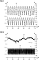
- Figure 1 shows a first load profile 1 of a battery, the voltage U in volts on the left y-axis, the current I in amperes on the right y-axis and the time in hours on the x-axis.
- the battery is charged and discharged using a photovoltaic system. It can be seen that only a few current or voltage changes take place.
- This first load profile 1 typically comprises between 5 and 20 voltage changes or current changes per 100 hours.
- a voltage swing or voltage change in the first load profile 1V is in particular in a range between 0.7 and 2 V.
- the current swing or current change in the first load profile 1A is typically in a range between +/- 5 A and +/- 30 A.
- Figure 2 shows how Figure 1 , on the left y-axis the voltage U in volts, on the right y-axis the current I in amperes and on the x-axis the time in hours.
- the diagram shows the second load profile 2 when the battery is operated with many small voltage and current changes, in particular when using primary control power.
- the many small voltage and current changes are called microcycles here.
- Many voltage or current changes mean in particular at least 4 voltage changes per hour. This is advantageous because in electricity trading it is typically every 15 minutes is billed.
- Small current changes are in particular in the order of magnitude between 0 and +/- 15 A.
- Small voltage changes, also known as voltage swings are in a range from 0.5 V to 0.1 V. The power swing can be calculated using the product of current and voltage swings become.
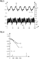
- Figure 3 again shows current I and voltage U against time and depicts a third load profile in which the first load profile 1 and the second load profile 2 are superimposed.
- Figure 4 shows the current capacity per initial capacity 4 on the y-axis and the equivalent full cycles on the x-axis.
- the equivalent full cycle is defined as: Sum of the energy put through by the storage capacity of the storage system. For example, both 100 full charge / discharge cycles and 400 25% charge / discharge cycles add up to 200 equivalent full cycles.
- Figure 4 shows a first loss of capacity 11 of the battery when operating with the first load profile 1, a second loss of capacity 12 of the battery when operating with the second load profile 2 and a third loss of capacity 13 of the battery when operating with the third superimposed load profile 3.
- first loss of capacity which describes the operation of the battery with the photovoltaic system
- the second load profile 2 also leads to a second loss of capacity of the battery.
- this second loss of capacity is significantly less than the first loss of capacity.
- Even with 1000 full cycles the capacity is still 85% compared to the initial capacity.
- the third load profile in which the first and second load profiles are superimposed, has the lowest third capacity loss 13. At 1000 full cycles, the capacity is still advantageously 90% of the original capacity.
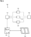
- FIG. 5 shows a battery storage system 100 with a battery 101, a photovoltaic system 102 and a control unit 104.
- the battery 101 is electrically connected to the photovoltaic system 102. Depending on the solar radiation, the battery is operated with a load profile, in particular with a first load profile 1. Furthermore, the battery 101 is connected to a control unit 104. This control unit is suitable for imposing microcycles on the battery.
- the control unit 104 can draw the electricity either as primary control power 105, as secondary control power 106 or from the electricity market 107.
- the power grid 108 is thus connected directly or indirectly to the control unit 104.
- the control unit 104 superimposes the first load profile 1 of the photovoltaic system 102 with a second load profile 2 comprising microcycles in such a way that the loss of capacity of the battery is advantageously very low.
- the control unit comprises several functions: According to the invention, it evaluates the first load profile on the battery, according to the invention determines the second load profile based thereon and superimposes the first load profile in the battery with the second load profile and controls the imprint of the second load profile in terms of power and frequency and determines the capacity of the battery and the losses.
Landscapes
- Engineering & Computer Science (AREA)
- Power Engineering (AREA)
- Chemical & Material Sciences (AREA)
- Chemical Kinetics & Catalysis (AREA)
- Electrochemistry (AREA)
- General Chemical & Material Sciences (AREA)
- Manufacturing & Machinery (AREA)
- Materials Engineering (AREA)
- Inorganic Chemistry (AREA)
- Charge And Discharge Circuits For Batteries Or The Like (AREA)
- Secondary Cells (AREA)
Description
- Die Erfindung betrifft ein Batteriespeichersystem und ein Verfahren zum Betreiben eines Batteriespeichersystems.
- Eine Batterie ist ein Speicher für elektrische Energie auf elektrochemischer Basis. Handelt es sich um einen wiederaufladbaren Speicher wird dieser auch Akkumulator genannt. Ein einzelnes wiederaufladbares Speicherelement wird auch Sekundärelement genannt.
- Batteriespeichersysteme, welche typischerweise eine Batterie, einen Wechselrichter und eine Steuerung umfassen, können neben der Energiespeicherung auch Netzdienstleistungen erbringen, also Leistung aus dem Stromnetz, insbesondere dem öffentlichen Stromnetz, entnehmen und dabei selbst geladen werden oder Leistung an ein Stromnetz abgeben und dabei selbst entladen werden. Aufgrund der schnellen Reaktionszeiten von Batterien ist das Laden und Entladen langfristig, insbesondere über mehrere Stunden, oder kurzfristig, insbesondere innerhalb von Sekunden, möglich.
- Die
US 2011/0204720 A1 offenbart ein Verfahren zum effizienten Betreiben eines Batteriespeichers, insbesondere für Gebäude oder Fahrzeuge. - Die
US 2007/0170895 A1 offenbart ein Verfahren zum Laden eines Batteriespeichers, insbesondere mittels amplituden- oder frequenzmodulierter elektrischer Energie. - Durch Lade- und Entladevorgänge kommt es allerdings nachteilig zu teilweise irreversiblen elektrochemischen Vorgängen an den Elektroden des Batteriesystems. Weiterhin sind die Anforderungen an die Batterie hinsichtlich Nutzung und Lebensdauer gegensätzlich. Einerseits nimmt die Belastbarkeit bei höheren Temperaturen durch eine bessere Ionenbeweglichkeit zu, andererseits führt diese höhere Ionenbeweglichkeit durch die höhere Reaktionsfähigkeit der Elektrodenmaterialen nachteilig zu einer abnehmenden Lebensdauer und Kapazität.
- Es ist daher Aufgabe der vorliegenden Erfindung ein Batteriespeichersystem und ein Verfahren zum Betrieb eines Batteriespeichersystems anzugeben, welches die Lebensdauer der Batterie verlängert.
- Die Aufgabe wird mit einem Verfahren zum Betreiben eines Batteriespeichersystems gemäß Anspruch 1 und einem Batteriespeichersystem gemäß Anspruch 12 gelöst.
- Das erfindungsgemäße Verfahren zum Betreiben eines Batteriespeichersystems umfasst mehrere Schritte. Wenigstens eine Batterie wird mit einem ersten Lastprofil mit einer ersten Anzahl Belastungszyklen pro Stunde mit einem ersten Leistungshub betrieben. Weiterhin wird eine Steuereinheit betrieben, welche ausgebildet ist, ein zweites Lastprofil zu generieren, wobei das zweite Lastprofil eine zweite Anzahl Belastungszyklen pro Stunde mit einem zweiten Leistungshub umfasst und die Steuereinheit ausgebildet ist, die Batterie mit dem zweiten Lastprofil zu beaufschlagen. Die Batterie wird mit dem zweiten Lastprofil beaufschlagt, wobei das erste Lastprofil mit dem zweiten Lastprofil überlagert wird und wobei die zweite Anzahl Belastungszyklen pro Stunde größer als die erste Anzahl Belastungszyklen pro Stunde ist und der zweite Leistungshub kleiner als der erste Leistungshub ist.
- Als Lastprofil wird die zeitabhängige Belastung der Batterie mit Be- und Entladevorgängen bezeichnet, wobei die Be- und Entladevorgänge aus unterschiedlichen Stromquellen oder Stromsenken resultieren können. Als das erste Lastprofil kann genau ein Lastprofil oder mehrere sich überlagernde Lastprofile unterschiedlicher Verbraucher der Batterie verstanden werden.
- Als Leistungshub wird hierbei der Unterschied in der Leistung der Batterie pro Zeiteinheit, insbesondere pro Stunde, bezeichnet.
- Als Belastungszyklus wird hier eine Abfolge von einem Be- und einem Entladen der Batterie verstanden.
- Das erfindungsgemäße Batteriespeichersystem zum Betreiben einer Batterie gemäß dem oben genannten Verfahren umfasst eine Batterie, welche geeignet ist zum Betreiben mit einem ersten Lastprofil mit einer ersten Anzahl Belastungszyklen pro Stunde mit einem ersten Leistungshub. Das Batteriespeichersystem umfasst weiterhin eine Steuereinheit, welche geeignet ist, die Batterie mit einem zweiten Lastprofil mit einer zweiten Anzahl Belastungszyklen pro Stunde mit einem zweiten Leistungshub zu beaufschlagen. Die zweite Anzahl Belastungszyklen pro Stunde ist größer als die erste Anzahl Belastungszyklen pro Stunde und der zweite Leistungshub ist kleiner als der erste Leistungshub.
- Es wurde im Rahmen der Erfindung erkannt, dass die Batterie überraschenderweise einen geringeren Kapazitätsverlust aufweist, wenn ein erstes Lastprofil, welches insbesondere einen Belastungszyklus aufweist, welcher wenigstens mehrere Stunden beträgt, von einem zweiten Lastprofil überlagert wird, welches Mikrozyklen, also sehr kurze Belastungszyklen aufweist, welche insbesondere wenige Sekunden dauern. Der Kapazitätsverlust der Batterie ist dann vorteilhaft geringer als beim alleinigen Beaufschlagen der Batterie mit dem ersten Lastprofil.
- In einer vorteilhaften Ausgestaltung und Weiterbildung der Erfindung liegt der zweite Leistungshub des zweiten Lastprofils in einem Bereich, der kleiner ist als die Hälfte des ersten Leistungshubs des ersten Lastprofils. Vorteilhaft ist der Kapazitätsverlust der Batterie beim Überlagern des ersten Lastprofils mit dem zweiten Lastprofil dann deutlich geringer.
- In einer weiteren vorteilhaften Ausgestaltung und Weiterbildung der Erfindung liegt das zweite Lastprofil in einem Bereich zwischen 0,1 % und 15 % einer Entladungstiefe der Batterie. In diesem Bereich wird die Batterie vorteilhaft durch das Aufprägen des zweiten Lastprofils nicht zusätzlich gestresst, sondern der Kapazitätsverlust wird vorteilhaft verringert.
- In einer weiteren vorteilhaften Ausgestaltung und Weiterbildung der Erfindung weist das zweite Lastprofil C raten von maximal C/6 auf. Besonders bevorzugt weist das zweite Lastprofil C raten zwischen C/6 und C/2 auf.
- In einer weiteren vorteilhaften Ausgestaltung und Weiterbildung der Erfindung wird das zweite Lastprofil derart generiert, dass es eine zum ersten Lastprofil entgegengesetzte Phase aufweist. Vorteilhaft werden dadurch die Absolutbelastungen der Batterie verringert und es wird eine Gegenreaktion der Batteriechemie erzeugt, welche vorteilhaft zu einer Homogenisierung innerhalb der Elektrodenmaterialen führt. Dies führt vorteilhaft zu einer längeren Lebensdauer der Batterie.
- Das zweite Lastprofil wird insbesondere aus Primärregelleistung, Sekundärregelleistung oder aus einem Stromhandel generiert. Diesen Systemen kann sowohl elektrische Leistung entzogen als auch zugeführt werden.
- In einer weiteren vorteilhaften Ausgestaltung und Weiterbildung der Erfindung erfolgt die Überlagerung des ersten und zweiten Lastprofils in einem Batterietemperaturbereich zwischen 15 °C und 35 °C. In diesem Temperaturbereich der Batterie werden die Batterien nicht durch sehr hohe oder sehr niedrige Temperaturen gestresst, sodass ein Kapazitätsverlust vorteilhaft niedrig gehalten wird.
- In einer weiteren vorteilhaften Ausgestaltung und Weiterbildung der Erfindung setzt das erste Lastprofil eine erste Energiemenge um und das zweite Lastprofil setzt eine zweite Energiemenge um. Die zweite Energiemenge liegt in einem Bereich von 5 % bis 40 % der ersten Energiemenge. Vorteilhaft wird dadurch die Energiemenge für das zweite Lastprofil eingeschränkt.
- In einer weiteren vorteilhaften Ausgestaltung und Weiterbildung der Erfindung weist das erste Lastprofil eine erste Maximalleistung auf. Das zweite Lastprofil weist eine zweite Maximalleistung auf. Die zweite Maximalleistung beträgt weniger als 50 % der ersten Maximalleistung des ersten Lastprofils. Vorteilhaft ist es dadurch möglich die Gesamtleistung des Systems nicht zu groß auszulegen, was wiederum eine geringere Gesamtleistung zur Folge hat. Weiterhin werden geringere Stromtragfähigkeiten der Zuleitungen vorteilhaft eingehalten. Vorteilhaft wird dadurch auch lediglich ein begrenzter Spannungshub bei Aufprägung des zweiten Lastprofils auf die Batterie erzeugt.
- In einer weiteren vorteilhaften Ausgestaltung und Weiterbildung der Erfindung wird die Batterie mit dem Lastprofil einer Photovoltaikanlage als erstem Lastprofil betrieben.
- In einer weiteren vorteilhaften Ausgestaltung und Weiterbildung der Erfindung wird als Batterie ein Lithium-Ionen-Speicher verwendet.
- In einer weiteren vorteilhaften Ausgestaltung und Weiterbildung der Erfindung weist der Lithium-Ionen Speicher eine Nickel-Kobalt-Aluminium-Kathode auf.
- Weitere Merkmale, Eigenschaften und Vorteile der vorliegenden Erfindung ergeben sich aus der nachfolgenden Beschreibung unter Bezugnahme auf die beiliegenden Figuren. Darin zeigen schematisch:
- Figur 1
- ein erstes Lastprofil einer Batterie bei Betrieb einer Photovoltaikanlage;
- Figur 2
- ein zweites Lastprofil der Batterie mit Mikrozyklen;
- Figur 3
- ein drittes Lastprofil einer Batterie mit dem ersten und zweiten Lastprofil überlagert;
- Figur 4
- ein Vergleich der Kapazitätsverluste der Batterie in Betrieb mit dem ersten Lastprofil, dem zweiten Last-profil und dem überlagerten Lastprofil;
- Figur 5
- ein Batteriespeichersystem.
-
Figur 1 zeigt ein erstes Lastprofil 1 einer Batterie, wobei auf der linken y-Achse die Spannung U in Volt, auf der rechten y-Achse der Strom I in Ampere und auf der x-Achse die Zeit in Stunden aufgetragen ist. Die Batterie wird mittels einer Photovoltaikanlage be- und entladen. Es ist zu sehen, dass nur wenige Strom- bzw. Spannungswechsel stattfinden. Typischerweise umfasst dieses erste Lastprofil 1 zwischen 5 und 20 Spannungswechsel bzw. Stromwechsel pro 100 Stunden. Ein Spannungshub, bzw. Spannungswechsel liegt bei dem ersten Lastprofil 1V insbesondere in einem Bereich zwischen 0,7 und 2 V. Der Stromhub, bzw. Stromwechsel des ersten Lastprofils 1A liegt typischerweise in einem Bereich zwischen +/- 5 A und +/- 30 A. -
Figur 2 zeigt, wieFigur 1 , auf der linken y-Achse die Spannung U in Volt, auf der rechten y-Achse den Strom I in Ampere und auf der x-Achse die Zeit in Stunden. Das Diagramm zeigt das zweite Lastprofil 2 beim Betrieb der Batterie mit vielen kleinen Spannungs- und Stromwechseln, insbesondere bei der Anwendung der Primärregelleistungserbringung. Die vielen kleinen Spannungs- und Stromwechsel werden hier Mikrozyklen genannt. Viele Spannungs- bzw. Stromwechsel bedeuten insbesondere wenigstens 4 Spannungswechsel in der Stunde. Dies ist vorteilhaft, da im Stromhandel typischerweise alle 15 Minuten abgerechnet wird. Kleine Stromwechsel liegen insbesondere in einer Größenordnung zwischen 0 und +/- 15 A. Geringe Spannungswechsel, auch Spannungshub genannt, liegen in einem Bereich von 0,5 V bis 0,1 V. Der Leistungshub kann anhand des Produkts aus Strom- und Spannungshüben berechnet werden. -
Figur 3 zeigt wiederum Strom I und Spannung U gegen die Zeit und bildet ein drittes Lastprofil ab, in dem das erste Lastprofil 1 und das zweite Lastprofil 2 überlagert werden. -
Figur 4 zeigt die aktuelle Kapazität pro anfänglicher Kapazität 4 auf der y-Achse und die äquivalenten Vollzyklen auf der x-Achse. Als äquivalenter Vollzyklus wird definiert: Summe der durchgesetzten Energie durch die Speicherkapazität des Speichersystems. Beispielsweise sind sowohl 100 volle Lade/Entladezyklen und 400 25% Lade/Entladezyklen in der Summe 200 äquivalente Vollzyklen. -
Figur 4 zeigt einen ersten Kapazitätsverlust 11 der Batterie bei Betrieb mit dem ersten Lastprofil 1, einen zweiten Kapazitätsverlust 12 der Batterie bei Betrieb mit dem zweiten Lastprofil 2 und einen dritten Kapazitätsverlust 13 der Batterie bei Betrieb mit dem dritten überlagerten Lastprofil 3. Es ist deutlich zu sehen dass der erste Kapazitätsverlust, der den Betrieb der Batterie mit der Photovoltaikanlage beschreibt, am größten ist. Bereits bei knapp 500 Vollzyklen ist die Kapazität bezogen auf die anfängliche Kapazität von 1 auf 0,67 gesunken. Auch das zweite Lastprofil 2 führt zu einem zweiten Kapazitätsverlust der Batterie. Dieser zweite Kapazitätsverlust ist jedoch deutlich geringer als der erste Kapazitätsverlust. Auch bei 1000 Vollzyklen beträgt die Kapazität im Vergleich zur anfänglich Kapazität noch 85 %. Es hat sich überraschend gezeigt, dass das dritte Lastprofil, bei welchem das erste und zweite Lastprofil überlagert werden, den geringsten dritten Kapazitätsverlust 13 aufweist. Bei 1000 Vollzyklen beträgt die Kapazität vorteilhaft immer noch 90 % der ursprünglichen Kapazität. -
Figur 5 zeigt ein Batteriespeichersystem 100 mit einer Batterie 101, einer Photovoltaikanlage 102 und einer Steuereinheit 104. Die Batterie 101 ist mit der Photovoltaikanlage 102 elektrisch verbunden. Je nach Sonneneinstrahlung wird die Batterie mit einem Lastprofil, insbesondere mit einem ersten Lastprofil 1 betrieben. Weiterhin ist die Batterie 101 mit einer Steuereinheit 104 verbunden. Diese Steuereinheit ist dazu geeignet Mikrozyklen auf die Batterie aufzuprägen. Die Steuereinheit 104 kann den Strom entweder als Primärregelleistung 105, als Sekundärregelleistung 106 oder aus dem Strommarkt 107 entnehmen. Das Stromnetz 108 ist somit direkt oder indirekt mit der Steuereinheit 104 verbunden. Die Steuereinheit 104 überlagert das erste Lastprofil 1 der Photovoltaikanlage 102 derart mit einem zweiten Lastprofil 2 umfassend Mikrozyklen, dass der Kapazitätsverlust der Batterie vorteilhaft sehr gering ist. Die Steuereinheit umfasst dabei mehrere Funktionen: Sie wertet erfindungsgemäß das erste Lastprofil an der Batterie aus, bestimmt erfindungsgemäß darauf beruhend das zweite Lastprofil und überlagert das erste Lastprofil in der Batterie mit dem zweiten Lastprofil und steuert die Aufprägung des zweiten Lastprofils hinsichtlich der Leistung und der Frequenz und bestimmt dabei die Kapazität der Batterie und der Verluste.
Claims (14)
- Verfahren zum Betreiben eines Batteriespeichersystems (100) mit folgenden Schritten:- Betreiben wenigstens einer Batterie (101) mit einem ersten Lastprofil (1) mit einer ersten Anzahl Belastungszyklen pro Stunde mit einem ersten Leistungshub,- Betreiben einer Steuereinheit (104) ausgebildet zum Auswerten des ersten Lastprofils an der Batterie, zum Bestimmen eines darauf beruhenden zweiten Lastprofils und zum Generieren des zweiten Lastprofils (2) mit einer zweiten Anzahl Belastungszyklen pro Stunde mit einem zweiten Leistungshub und ausgebildet zum Beaufschlagen der Batterie (101) mit dem zweiten Lastprofil (2),- Beaufschlagen der Batterie (101) mit dem zweiten Lastprofil (2), wobei das ersten Lastprofil (1) mit dem zweiten Lastprofil (2) überlagert wird und wobei die zweite Anzahl Belastungszyklen pro Stunde größer als die erste Anzahl Belastungszyklen pro Stunde ist und der zweite Leistungshub kleiner als der erste Leistungshub ist.
- Verfahren nach Anspruch 1, wobei der zweite Leistungshub des zweiten Lastprofils (2) in einem Bereich kleiner als die Hälfte des ersten Leistungshubs des ersten Lastprofils (1) liegt.
- Verfahren nach einem der vorhergehenden Ansprüche, wobei das zweite Lastprofil (2) in einem Bereich zwischen 0,1% und 15% einer Entladungstiefe der Batterie liegt.
- Verfahren nach Anspruch 3, wobei das zweite Lastprofil (2) in einem Bereich zwischen 5% und 15% der Entladungstiefe der Batterie (101) liegt.
- Verfahren nach einem der vorhergehenden Ansprüche, wobei das zweite Lastprofil (2) C-Raten von maximal C/6 aufweist.
- Verfahren nach Anspruch 5, wobei das zweite Lastprofil (2) C-Raten zwischen C/6 und C/2 aufweist.
- Verfahren nach einem der vorhergehenden Ansprüche, wobei die Überlagerung des ersten (1) und zweiten Lastprofils (2) in einem Batterie-Temperaturbereich zwischen 15°C und 35°C erfolgt.
- Verfahren nach einem der vorhergehenden Ansprüche, wobei das erste Lastprofil (1) eine erste Energiemenge umsetzt das zweite Lastprofil (2) eine zweite Energiemenge umsetzt und die zweite Energiemenge in einem Bereich von 5% bis 40% der ersten Energiemenge liegt.
- Verfahren nach einem der vorhergehenden Ansprüche, wobei das erste Lastprofil (1) eine erste Maximalleistung aufweist und das zweite Lastprofil (2) eine zweite Maximalleistung aufweist und die zweite Maximalleistung weniger als 50% der ersten Maximalleistung des ersten Lastprofils beträgt.
- Verfahren nach einem der vorhergehenden Ansprüche, wobei das erste Lastprofil (1) ein Lastprofil einer Photovoltaikanlage (102) ist.
- Verfahren nach einem der vorhergehenden Ansprüche, wobei als Batterie (101) ein Lithium-Ionen-Speicher verwendet wird.
- Batteriespeichersystem (100) zum Betreiben mit einem Verfahren gemäß einem der Ansprüche 1 bis 11 umfassend:- eine Batterie (101) eingerichtet zum Betreiben mit einem ersten Lastprofil (1) mit einer ersten Anzahl Belastungszyklen pro Stunde mit einem ersten Leistungshub,- eine Steuereinheit (104) eingerichtet zum Auswerten des ersten Lastprofils an der Batterie, zum Bestimmen eines darauf beruhenden zweiten Lastprofils und zum Beaufschlagen der Batterie (101) mit dem zweiten Lastprofil (2) mit einer zweiten Anzahl Belastungszyklen pro Stunde mit einem zweiten Leistungshub, wobei die zweite Anzahl Belastungszyklen pro Stunde größer als die erste Anzahl Belastungszyklen pro Stunde ist und der zweite Leistungshub kleiner als der erste Leistungshub ist.
- Batteriespeichersystem (100) nach Anspruch 12, wobei die Batterie (101) ein Lithium-Ionen-Speicher ist.
- Batteriespeichersystem (100) nach Anspruch 13, wobei der Lithium-Ionen-Speicher eine Nickel-Cobalt-Aluminium-Kathode aufweist.
Applications Claiming Priority (2)
| Application Number | Priority Date | Filing Date | Title |
|---|---|---|---|
| DE102017207639.9A DE102017207639A1 (de) | 2017-05-05 | 2017-05-05 | Batteriespeichersystem und Verfahren zum Betreiben des Batteriespeichersystems |
| PCT/EP2018/059618 WO2018202408A1 (de) | 2017-05-05 | 2018-04-16 | Batteriespeichersystem und verfahren zum betreiben des batteriespeichersystems |
Publications (2)
| Publication Number | Publication Date |
|---|---|
| EP3583676A1 EP3583676A1 (de) | 2019-12-25 |
| EP3583676B1 true EP3583676B1 (de) | 2021-05-26 |
Family
ID=62063004
Family Applications (1)
| Application Number | Title | Priority Date | Filing Date |
|---|---|---|---|
| EP18720155.3A Active EP3583676B1 (de) | 2017-05-05 | 2018-04-16 | Batteriespeichersystem und verfahren zum betreiben des batteriespeichersystems |
Country Status (4)
| Country | Link |
|---|---|
| EP (1) | EP3583676B1 (de) |
| DE (1) | DE102017207639A1 (de) |
| ES (1) | ES2882572T3 (de) |
| WO (1) | WO2018202408A1 (de) |
Citations (1)
| Publication number | Priority date | Publication date | Assignee | Title |
|---|---|---|---|---|
| US20070170895A1 (en) * | 2006-01-25 | 2007-07-26 | Dardik Irving I | Battery charging with superwaves |
Family Cites Families (2)
| Publication number | Priority date | Publication date | Assignee | Title |
|---|---|---|---|---|
| HU196863B (en) * | 1986-12-01 | 1989-01-30 | Brg Mechatronikai Vallalat | Method for charging ni-cd accumulators and circuit arrangement for carrying out the said method |
| US8872379B2 (en) * | 2007-11-30 | 2014-10-28 | Johnson Controls Technology Company | Efficient usage, storage, and sharing of energy in buildings, vehicles, and equipment |
-
2017
- 2017-05-05 DE DE102017207639.9A patent/DE102017207639A1/de not_active Withdrawn
-
2018
- 2018-04-16 WO PCT/EP2018/059618 patent/WO2018202408A1/de not_active Ceased
- 2018-04-16 EP EP18720155.3A patent/EP3583676B1/de active Active
- 2018-04-16 ES ES18720155T patent/ES2882572T3/es active Active
Patent Citations (1)
| Publication number | Priority date | Publication date | Assignee | Title |
|---|---|---|---|---|
| US20070170895A1 (en) * | 2006-01-25 | 2007-07-26 | Dardik Irving I | Battery charging with superwaves |
Also Published As
| Publication number | Publication date |
|---|---|
| WO2018202408A1 (de) | 2018-11-08 |
| EP3583676A1 (de) | 2019-12-25 |
| ES2882572T3 (es) | 2021-12-02 |
| DE102017207639A1 (de) | 2018-11-08 |
Similar Documents
| Publication | Publication Date | Title |
|---|---|---|
| EP3275040B1 (de) | Verfahren und vorrichtung zum formieren einer batterie | |
| DE112017004673B4 (de) | Energie-Umwandlungsvorrichtung | |
| DE102021203390B3 (de) | Verfahren zum spannungsgeführten Betrieb eines Batteriesystems während eines Ladevorgangs | |
| DE10158062A1 (de) | Verfahren und Vorrichtung zum Laden von Batterien mit reduzierten Überladeniveaus | |
| DE102013105119A1 (de) | Verfahren und Vorrichtung zum Laden von wiederaufladbaren Zellen | |
| DE102007026003A1 (de) | Brennstoffzellensystem mit verbesserten Kaltstarteigenschaften sowie Verfahren | |
| EP3371847A1 (de) | Verfahren zum betrieb einer batterie und batterie | |
| EP3314688B1 (de) | Verfahren zum steuern eines regenerationsvorganges einer lithiumionenbatteriezelle, welche eine anode, eine kathode und eine regenerationselektrode umfasst | |
| EP2617115A2 (de) | Verfahren zum laden einer batterie eines kraftwagens | |
| WO2019101443A1 (de) | Verfahren zum betreiben einer elektrischen energiespeichereinrichtung für ein kraftfahrzeug sowie entsprechende energiespeichereinrichtung | |
| DE102012207674A1 (de) | Verfahren und Vorrichtung zum Einstellen der Ladezustände einer Batterie | |
| DE102009051731B4 (de) | Verfahren und Vorrichtung zum Laden einer Batterie | |
| EP3583676B1 (de) | Batteriespeichersystem und verfahren zum betreiben des batteriespeichersystems | |
| DE102016221335A1 (de) | Verfahren zum Betreiben eines Systems zur Versorgung eines Fahrzeugs mit elektrischer Energie und System | |
| EP3509159A1 (de) | Batteriesystem für ein elektrofahrzeug, verfahren zum laden eines batteriesystems und elektrofahrzeug | |
| EP4505572B1 (de) | Verfahren zum aufladen eines wiederaufladbaren energiespeichers | |
| EP3533103A1 (de) | Verfahren zum herstellen einer lithium-ionen-zelle und einer lithium-ionen-batterie, lithium-ionen-batterie | |
| WO2014139878A1 (de) | Verfahren zur bestimmung des ladezustands eines akkumulators | |
| DE102011089955B4 (de) | Verfahren zur Leistungssteigerung einer Batterie, Batterie-Management-System und Kraftfahrzeug | |
| DE102018217726A1 (de) | Verfahren zum Betreiben eines Systems zur Bereitstellung elektrischer Energie | |
| DE102022201841A1 (de) | Verfahren und Vorrichtung zum Durchführen eines Ladevorgangs einer Gerätebatterie eines batteriebetriebenen Geräts | |
| DE102024114152B4 (de) | Verfahren zum Pulsentladen | |
| DE102016007804A1 (de) | Batterie für ein Fahrzeug | |
| EP3895246A1 (de) | Verfahren zum betreiben eines elektrischen energiespeichers | |
| EP2446503A1 (de) | Verfahren und vorrichtung zum laden von lithium-kobalt zellen |
Legal Events
| Date | Code | Title | Description |
|---|---|---|---|
| STAA | Information on the status of an ep patent application or granted ep patent |
Free format text: STATUS: UNKNOWN |
|
| STAA | Information on the status of an ep patent application or granted ep patent |
Free format text: STATUS: THE INTERNATIONAL PUBLICATION HAS BEEN MADE |
|
| PUAI | Public reference made under article 153(3) epc to a published international application that has entered the european phase |
Free format text: ORIGINAL CODE: 0009012 |
|
| STAA | Information on the status of an ep patent application or granted ep patent |
Free format text: STATUS: REQUEST FOR EXAMINATION WAS MADE |
|
| 17P | Request for examination filed |
Effective date: 20190920 |
|
| AK | Designated contracting states |
Kind code of ref document: A1 Designated state(s): AL AT BE BG CH CY CZ DE DK EE ES FI FR GB GR HR HU IE IS IT LI LT LU LV MC MK MT NL NO PL PT RO RS SE SI SK SM TR |
|
| AX | Request for extension of the european patent |
Extension state: BA ME |
|
| DAV | Request for validation of the european patent (deleted) | ||
| DAX | Request for extension of the european patent (deleted) | ||
| STAA | Information on the status of an ep patent application or granted ep patent |
Free format text: STATUS: EXAMINATION IS IN PROGRESS |
|
| 17Q | First examination report despatched |
Effective date: 20200921 |
|
| RIC1 | Information provided on ipc code assigned before grant |
Ipc: H02J 7/00 20060101AFI20201110BHEP Ipc: H01M 10/0525 20100101ALI20201110BHEP Ipc: H01M 4/525 20100101ALI20201110BHEP Ipc: H02J 3/32 20060101ALI20201110BHEP Ipc: H01M 10/44 20060101ALI20201110BHEP |
|
| GRAP | Despatch of communication of intention to grant a patent |
Free format text: ORIGINAL CODE: EPIDOSNIGR1 |
|
| STAA | Information on the status of an ep patent application or granted ep patent |
Free format text: STATUS: GRANT OF PATENT IS INTENDED |
|
| INTG | Intention to grant announced |
Effective date: 20210112 |
|
| GRAS | Grant fee paid |
Free format text: ORIGINAL CODE: EPIDOSNIGR3 |
|
| GRAA | (expected) grant |
Free format text: ORIGINAL CODE: 0009210 |
|
| STAA | Information on the status of an ep patent application or granted ep patent |
Free format text: STATUS: THE PATENT HAS BEEN GRANTED |
|
| AK | Designated contracting states |
Kind code of ref document: B1 Designated state(s): AL AT BE BG CH CY CZ DE DK EE ES FI FR GB GR HR HU IE IS IT LI LT LU LV MC MK MT NL NO PL PT RO RS SE SI SK SM TR |
|
| REG | Reference to a national code |
Ref country code: GB Ref legal event code: FG4D Free format text: NOT ENGLISH |
|
| REG | Reference to a national code |
Ref country code: CH Ref legal event code: EP |
|
| REG | Reference to a national code |
Ref country code: DE Ref legal event code: R096 Ref document number: 502018005447 Country of ref document: DE |
|
| REG | Reference to a national code |
Ref country code: AT Ref legal event code: REF Ref document number: 1397208 Country of ref document: AT Kind code of ref document: T Effective date: 20210615 |
|
| REG | Reference to a national code |
Ref country code: IE Ref legal event code: FG4D Free format text: LANGUAGE OF EP DOCUMENT: GERMAN |
|
| REG | Reference to a national code |
Ref country code: LT Ref legal event code: MG9D |
|
| PG25 | Lapsed in a contracting state [announced via postgrant information from national office to epo] |
Ref country code: BG Free format text: LAPSE BECAUSE OF FAILURE TO SUBMIT A TRANSLATION OF THE DESCRIPTION OR TO PAY THE FEE WITHIN THE PRESCRIBED TIME-LIMIT Effective date: 20210826 Ref country code: LT Free format text: LAPSE BECAUSE OF FAILURE TO SUBMIT A TRANSLATION OF THE DESCRIPTION OR TO PAY THE FEE WITHIN THE PRESCRIBED TIME-LIMIT Effective date: 20210526 Ref country code: HR Free format text: LAPSE BECAUSE OF FAILURE TO SUBMIT A TRANSLATION OF THE DESCRIPTION OR TO PAY THE FEE WITHIN THE PRESCRIBED TIME-LIMIT Effective date: 20210526 Ref country code: FI Free format text: LAPSE BECAUSE OF FAILURE TO SUBMIT A TRANSLATION OF THE DESCRIPTION OR TO PAY THE FEE WITHIN THE PRESCRIBED TIME-LIMIT Effective date: 20210526 |
|
| REG | Reference to a national code |
Ref country code: NL Ref legal event code: MP Effective date: 20210526 |
|
| PG25 | Lapsed in a contracting state [announced via postgrant information from national office to epo] |
Ref country code: GR Free format text: LAPSE BECAUSE OF FAILURE TO SUBMIT A TRANSLATION OF THE DESCRIPTION OR TO PAY THE FEE WITHIN THE PRESCRIBED TIME-LIMIT Effective date: 20210827 Ref country code: IS Free format text: LAPSE BECAUSE OF FAILURE TO SUBMIT A TRANSLATION OF THE DESCRIPTION OR TO PAY THE FEE WITHIN THE PRESCRIBED TIME-LIMIT Effective date: 20210926 Ref country code: NO Free format text: LAPSE BECAUSE OF FAILURE TO SUBMIT A TRANSLATION OF THE DESCRIPTION OR TO PAY THE FEE WITHIN THE PRESCRIBED TIME-LIMIT Effective date: 20210826 Ref country code: PL Free format text: LAPSE BECAUSE OF FAILURE TO SUBMIT A TRANSLATION OF THE DESCRIPTION OR TO PAY THE FEE WITHIN THE PRESCRIBED TIME-LIMIT Effective date: 20210526 Ref country code: LV Free format text: LAPSE BECAUSE OF FAILURE TO SUBMIT A TRANSLATION OF THE DESCRIPTION OR TO PAY THE FEE WITHIN THE PRESCRIBED TIME-LIMIT Effective date: 20210526 Ref country code: PT Free format text: LAPSE BECAUSE OF FAILURE TO SUBMIT A TRANSLATION OF THE DESCRIPTION OR TO PAY THE FEE WITHIN THE PRESCRIBED TIME-LIMIT Effective date: 20210927 Ref country code: RS Free format text: LAPSE BECAUSE OF FAILURE TO SUBMIT A TRANSLATION OF THE DESCRIPTION OR TO PAY THE FEE WITHIN THE PRESCRIBED TIME-LIMIT Effective date: 20210526 Ref country code: SE Free format text: LAPSE BECAUSE OF FAILURE TO SUBMIT A TRANSLATION OF THE DESCRIPTION OR TO PAY THE FEE WITHIN THE PRESCRIBED TIME-LIMIT Effective date: 20210526 |
|
| REG | Reference to a national code |
Ref country code: ES Ref legal event code: FG2A Ref document number: 2882572 Country of ref document: ES Kind code of ref document: T3 Effective date: 20211202 |
|
| PG25 | Lapsed in a contracting state [announced via postgrant information from national office to epo] |
Ref country code: NL Free format text: LAPSE BECAUSE OF FAILURE TO SUBMIT A TRANSLATION OF THE DESCRIPTION OR TO PAY THE FEE WITHIN THE PRESCRIBED TIME-LIMIT Effective date: 20210526 |
|
| PG25 | Lapsed in a contracting state [announced via postgrant information from national office to epo] |
Ref country code: RO Free format text: LAPSE BECAUSE OF FAILURE TO SUBMIT A TRANSLATION OF THE DESCRIPTION OR TO PAY THE FEE WITHIN THE PRESCRIBED TIME-LIMIT Effective date: 20210526 Ref country code: DK Free format text: LAPSE BECAUSE OF FAILURE TO SUBMIT A TRANSLATION OF THE DESCRIPTION OR TO PAY THE FEE WITHIN THE PRESCRIBED TIME-LIMIT Effective date: 20210526 Ref country code: CZ Free format text: LAPSE BECAUSE OF FAILURE TO SUBMIT A TRANSLATION OF THE DESCRIPTION OR TO PAY THE FEE WITHIN THE PRESCRIBED TIME-LIMIT Effective date: 20210526 Ref country code: SM Free format text: LAPSE BECAUSE OF FAILURE TO SUBMIT A TRANSLATION OF THE DESCRIPTION OR TO PAY THE FEE WITHIN THE PRESCRIBED TIME-LIMIT Effective date: 20210526 Ref country code: SK Free format text: LAPSE BECAUSE OF FAILURE TO SUBMIT A TRANSLATION OF THE DESCRIPTION OR TO PAY THE FEE WITHIN THE PRESCRIBED TIME-LIMIT Effective date: 20210526 Ref country code: EE Free format text: LAPSE BECAUSE OF FAILURE TO SUBMIT A TRANSLATION OF THE DESCRIPTION OR TO PAY THE FEE WITHIN THE PRESCRIBED TIME-LIMIT Effective date: 20210526 |
|
| REG | Reference to a national code |
Ref country code: DE Ref legal event code: R097 Ref document number: 502018005447 Country of ref document: DE |
|
| PLBE | No opposition filed within time limit |
Free format text: ORIGINAL CODE: 0009261 |
|
| STAA | Information on the status of an ep patent application or granted ep patent |
Free format text: STATUS: NO OPPOSITION FILED WITHIN TIME LIMIT |
|
| 26N | No opposition filed |
Effective date: 20220301 |
|
| PG25 | Lapsed in a contracting state [announced via postgrant information from national office to epo] |
Ref country code: IS Free format text: LAPSE BECAUSE OF FAILURE TO SUBMIT A TRANSLATION OF THE DESCRIPTION OR TO PAY THE FEE WITHIN THE PRESCRIBED TIME-LIMIT Effective date: 20210926 Ref country code: AL Free format text: LAPSE BECAUSE OF FAILURE TO SUBMIT A TRANSLATION OF THE DESCRIPTION OR TO PAY THE FEE WITHIN THE PRESCRIBED TIME-LIMIT Effective date: 20210526 |
|
| REG | Reference to a national code |
Ref country code: CH Ref legal event code: PL |
|
| REG | Reference to a national code |
Ref country code: BE Ref legal event code: MM Effective date: 20220430 |
|
| PG25 | Lapsed in a contracting state [announced via postgrant information from national office to epo] |
Ref country code: MC Free format text: LAPSE BECAUSE OF FAILURE TO SUBMIT A TRANSLATION OF THE DESCRIPTION OR TO PAY THE FEE WITHIN THE PRESCRIBED TIME-LIMIT Effective date: 20210526 Ref country code: LU Free format text: LAPSE BECAUSE OF NON-PAYMENT OF DUE FEES Effective date: 20220416 Ref country code: LI Free format text: LAPSE BECAUSE OF NON-PAYMENT OF DUE FEES Effective date: 20220430 Ref country code: CH Free format text: LAPSE BECAUSE OF NON-PAYMENT OF DUE FEES Effective date: 20220430 |
|
| PG25 | Lapsed in a contracting state [announced via postgrant information from national office to epo] |
Ref country code: BE Free format text: LAPSE BECAUSE OF NON-PAYMENT OF DUE FEES Effective date: 20220430 |
|
| PG25 | Lapsed in a contracting state [announced via postgrant information from national office to epo] |
Ref country code: IE Free format text: LAPSE BECAUSE OF NON-PAYMENT OF DUE FEES Effective date: 20220416 |
|
| P01 | Opt-out of the competence of the unified patent court (upc) registered |
Effective date: 20230510 |
|
| PG25 | Lapsed in a contracting state [announced via postgrant information from national office to epo] |
Ref country code: MK Free format text: LAPSE BECAUSE OF FAILURE TO SUBMIT A TRANSLATION OF THE DESCRIPTION OR TO PAY THE FEE WITHIN THE PRESCRIBED TIME-LIMIT Effective date: 20210526 Ref country code: CY Free format text: LAPSE BECAUSE OF FAILURE TO SUBMIT A TRANSLATION OF THE DESCRIPTION OR TO PAY THE FEE WITHIN THE PRESCRIBED TIME-LIMIT Effective date: 20210526 |
|
| PG25 | Lapsed in a contracting state [announced via postgrant information from national office to epo] |
Ref country code: HU Free format text: LAPSE BECAUSE OF FAILURE TO SUBMIT A TRANSLATION OF THE DESCRIPTION OR TO PAY THE FEE WITHIN THE PRESCRIBED TIME-LIMIT; INVALID AB INITIO Effective date: 20180416 |
|
| REG | Reference to a national code |
Ref country code: AT Ref legal event code: MM01 Ref document number: 1397208 Country of ref document: AT Kind code of ref document: T Effective date: 20230416 |
|
| PG25 | Lapsed in a contracting state [announced via postgrant information from national office to epo] |
Ref country code: TR Free format text: LAPSE BECAUSE OF FAILURE TO SUBMIT A TRANSLATION OF THE DESCRIPTION OR TO PAY THE FEE WITHIN THE PRESCRIBED TIME-LIMIT Effective date: 20210526 |
|
| PG25 | Lapsed in a contracting state [announced via postgrant information from national office to epo] |
Ref country code: AT Free format text: LAPSE BECAUSE OF NON-PAYMENT OF DUE FEES Effective date: 20230416 |
|
| PG25 | Lapsed in a contracting state [announced via postgrant information from national office to epo] |
Ref country code: AT Free format text: LAPSE BECAUSE OF NON-PAYMENT OF DUE FEES Effective date: 20230416 |
|
| PG25 | Lapsed in a contracting state [announced via postgrant information from national office to epo] |
Ref country code: MT Free format text: LAPSE BECAUSE OF FAILURE TO SUBMIT A TRANSLATION OF THE DESCRIPTION OR TO PAY THE FEE WITHIN THE PRESCRIBED TIME-LIMIT Effective date: 20210526 |
|
| PGFP | Annual fee paid to national office [announced via postgrant information from national office to epo] |
Ref country code: DE Payment date: 20250620 Year of fee payment: 8 |
|
| PGFP | Annual fee paid to national office [announced via postgrant information from national office to epo] |
Ref country code: GB Payment date: 20250507 Year of fee payment: 8 |
|
| PGFP | Annual fee paid to national office [announced via postgrant information from national office to epo] |
Ref country code: IT Payment date: 20250417 Year of fee payment: 8 |
|
| PGFP | Annual fee paid to national office [announced via postgrant information from national office to epo] |
Ref country code: FR Payment date: 20250411 Year of fee payment: 8 |
|
| PGFP | Annual fee paid to national office [announced via postgrant information from national office to epo] |
Ref country code: ES Payment date: 20250721 Year of fee payment: 8 |
|
| PGFP | Annual fee paid to national office [announced via postgrant information from national office to epo] |
Ref country code: AT Payment date: 20260410 Year of fee payment: 5 |