EP3583614B1 - Elektrischer wickelkörper mit optimierten gebrauchseigenschaften und verbessertem schutz gegen überhitzung - Google Patents
Elektrischer wickelkörper mit optimierten gebrauchseigenschaften und verbessertem schutz gegen überhitzung Download PDFInfo
- Publication number
- EP3583614B1 EP3583614B1 EP18709276.2A EP18709276A EP3583614B1 EP 3583614 B1 EP3583614 B1 EP 3583614B1 EP 18709276 A EP18709276 A EP 18709276A EP 3583614 B1 EP3583614 B1 EP 3583614B1
- Authority
- EP
- European Patent Office
- Prior art keywords
- winding form
- form according
- phase change
- weight
- temperature
- Prior art date
- Legal status (The legal status is an assumption and is not a legal conclusion. Google has not performed a legal analysis and makes no representation as to the accuracy of the status listed.)
- Active
Links
Images
Classifications
-
- H—ELECTRICITY
- H01—ELECTRIC ELEMENTS
- H01F—MAGNETS; INDUCTANCES; TRANSFORMERS; SELECTION OF MATERIALS FOR THEIR MAGNETIC PROPERTIES
- H01F5/00—Coils
- H01F5/06—Insulation of windings
-
- C—CHEMISTRY; METALLURGY
- C08—ORGANIC MACROMOLECULAR COMPOUNDS; THEIR PREPARATION OR CHEMICAL WORKING-UP; COMPOSITIONS BASED THEREON
- C08L—COMPOSITIONS OF MACROMOLECULAR COMPOUNDS
- C08L25/00—Compositions of, homopolymers or copolymers of compounds having one or more unsaturated aliphatic radicals, each having only one carbon-to-carbon double bond, and at least one being terminated by an aromatic carbocyclic ring; Compositions of derivatives of such polymers
- C08L25/02—Homopolymers or copolymers of hydrocarbons
- C08L25/04—Homopolymers or copolymers of styrene
- C08L25/06—Polystyrene
-
- C—CHEMISTRY; METALLURGY
- C09—DYES; PAINTS; POLISHES; NATURAL RESINS; ADHESIVES; COMPOSITIONS NOT OTHERWISE PROVIDED FOR; APPLICATIONS OF MATERIALS NOT OTHERWISE PROVIDED FOR
- C09K—MATERIALS FOR MISCELLANEOUS APPLICATIONS, NOT PROVIDED FOR ELSEWHERE
- C09K5/00—Heat-transfer, heat-exchange or heat-storage materials, e.g. refrigerants; Materials for the production of heat or cold by chemical reactions other than by combustion
- C09K5/02—Materials undergoing a change of physical state when used
- C09K5/06—Materials undergoing a change of physical state when used the change of state being from liquid to solid or vice versa
- C09K5/063—Materials absorbing or liberating heat during crystallisation; Heat storage materials
-
- H—ELECTRICITY
- H01—ELECTRIC ELEMENTS
- H01B—CABLES; CONDUCTORS; INSULATORS; SELECTION OF MATERIALS FOR THEIR CONDUCTIVE, INSULATING OR DIELECTRIC PROPERTIES
- H01B3/00—Insulators or insulating bodies characterised by the insulating materials; Selection of materials for their insulating or dielectric properties
- H01B3/18—Insulators or insulating bodies characterised by the insulating materials; Selection of materials for their insulating or dielectric properties mainly consisting of organic substances
- H01B3/28—Insulators or insulating bodies characterised by the insulating materials; Selection of materials for their insulating or dielectric properties mainly consisting of organic substances natural or synthetic rubbers
-
- H—ELECTRICITY
- H01—ELECTRIC ELEMENTS
- H01B—CABLES; CONDUCTORS; INSULATORS; SELECTION OF MATERIALS FOR THEIR CONDUCTIVE, INSULATING OR DIELECTRIC PROPERTIES
- H01B3/00—Insulators or insulating bodies characterised by the insulating materials; Selection of materials for their insulating or dielectric properties
- H01B3/18—Insulators or insulating bodies characterised by the insulating materials; Selection of materials for their insulating or dielectric properties mainly consisting of organic substances
- H01B3/30—Insulators or insulating bodies characterised by the insulating materials; Selection of materials for their insulating or dielectric properties mainly consisting of organic substances plastics; resins; waxes
- H01B3/44—Insulators or insulating bodies characterised by the insulating materials; Selection of materials for their insulating or dielectric properties mainly consisting of organic substances plastics; resins; waxes vinyl resins; acrylic resins
- H01B3/441—Insulators or insulating bodies characterised by the insulating materials; Selection of materials for their insulating or dielectric properties mainly consisting of organic substances plastics; resins; waxes vinyl resins; acrylic resins from alkenes
-
- H—ELECTRICITY
- H01—ELECTRIC ELEMENTS
- H01B—CABLES; CONDUCTORS; INSULATORS; SELECTION OF MATERIALS FOR THEIR CONDUCTIVE, INSULATING OR DIELECTRIC PROPERTIES
- H01B3/00—Insulators or insulating bodies characterised by the insulating materials; Selection of materials for their insulating or dielectric properties
- H01B3/18—Insulators or insulating bodies characterised by the insulating materials; Selection of materials for their insulating or dielectric properties mainly consisting of organic substances
- H01B3/30—Insulators or insulating bodies characterised by the insulating materials; Selection of materials for their insulating or dielectric properties mainly consisting of organic substances plastics; resins; waxes
- H01B3/44—Insulators or insulating bodies characterised by the insulating materials; Selection of materials for their insulating or dielectric properties mainly consisting of organic substances plastics; resins; waxes vinyl resins; acrylic resins
- H01B3/442—Insulators or insulating bodies characterised by the insulating materials; Selection of materials for their insulating or dielectric properties mainly consisting of organic substances plastics; resins; waxes vinyl resins; acrylic resins from aromatic vinyl compounds
-
- H—ELECTRICITY
- H01—ELECTRIC ELEMENTS
- H01F—MAGNETS; INDUCTANCES; TRANSFORMERS; SELECTION OF MATERIALS FOR THEIR MAGNETIC PROPERTIES
- H01F27/00—Details of transformers or inductances, in general
- H01F27/28—Coils; Windings; Conductive connections
- H01F27/32—Insulating of coils, windings, or parts thereof
- H01F27/327—Encapsulating or impregnating
-
- H—ELECTRICITY
- H02—GENERATION; CONVERSION OR DISTRIBUTION OF ELECTRIC POWER
- H02K—DYNAMO-ELECTRIC MACHINES
- H02K15/00—Processes or apparatus specially adapted for manufacturing, assembling, maintaining or repairing of dynamo-electric machines
- H02K15/12—Impregnating, moulding insulation, heating or drying of windings, stators, rotors or machines
-
- H—ELECTRICITY
- H02—GENERATION; CONVERSION OR DISTRIBUTION OF ELECTRIC POWER
- H02K—DYNAMO-ELECTRIC MACHINES
- H02K3/00—Details of windings
- H02K3/30—Windings characterised by the insulating material
-
- H—ELECTRICITY
- H02—GENERATION; CONVERSION OR DISTRIBUTION OF ELECTRIC POWER
- H02K—DYNAMO-ELECTRIC MACHINES
- H02K5/00—Casings; Enclosures; Supports
- H02K5/24—Casings; Enclosures; Supports specially adapted for suppression or reduction of noise or vibrations
Definitions
- the invention relates to an electrical winding body which has improved performance properties as a result of being impregnated with a thermoplastic material filled with phase change material. These properties relate to improved heat dissipation, vibration damping, fixing of the windings and improved protection against overheating by exploiting the sensitive and latent heat storage properties during the transition from the semi-crystalline state of the polymer units to the amorphous one.
- Electrical bobbins comprise windings, usually insulated copper wires, wrapped around a core.
- the electrical winding body includes any type of coils in the form of windings and winding goods that are suitable for generating or detecting a magnetic field.
- These winding bodies are used in electrical equipment such as transformers, converters, rotors and stators of electrical machines. It is known ( DE19928323 ), to impregnate more highly stressed windings that are processed in winding bodies with synthetic resins in order to improve efficiency by minimizing power loss. The idea behind this is to replace the air-filled cavities between the windings with a synthetic resin.
- the synthetic resin has a higher thermal conductivity than air, so it can dissipate heat generated during use better.
- the synthetic resin also has a higher density than air and can therefore better compensate for imbalances and reduce vibrations. Impregnation serves to increase the insulation strength and also to fix the windings, improve heat dissipation from the winding body and protect against corrosion.
- Thermosets are used to fill the voids between the windings because they have very good fluidity in the liquid state, making them easier to penetrate the voids and more thermally stable.
- the disadvantage of duroplastics is that they have to be cured in an additional work step and the phase transition into the solid phase is irreversible and the materials are very brittle after curing. If a thermal overload occurs, these materials cannot compensate or absorb this overload and will be destroyed.
- Such a thermal overload can often occur with electrical winding bodies, which are always only in operation for a short time, ie in the range from seconds to a few minutes ( ⁇ 10 min), but are repeatedly in operation at more or less large intervals. Temperature control by adjusting the current intensity is often not provided for such winding bodies, or is not advisable.
- US20130264896 describes a cast body made of a stator consisting of a magnet coil on an iron core, encased with an injection resin, which includes a duroplastic resin and a thermoplastic resin which is incompatible with this and which contains inorganic additives (metal hydrates) and a thermal conductivity of ⁇ 1.5 W/m . K and a flame resistance according to UL94V-0.
- the amount of metal hydrate is ⁇ 2 parts of casting resin.
- a cast engine includes this cast body. The task was to find a plastic as an insulator that offers low shrinkage, high thermal conductivity and flame resistance at the same time.
- the injection resin forms a kind of housing for the stator, the way it is manufactured and the composition does not allow the injection resin to displace all the air between the windings, you achieve improved thermal management and vibration stability, but large quantities of injection resin are required and these Type of winding wrap is only suitable for stators.
- the solution in this patent is designed for a continuous load on the coil, for continuous heat dissipation through a highly thermally conductive plastic housing that transfers the heat to the surface.
- the winding of an electrical machine is known, which is enclosed with an insulating material.
- the insulator material is a cast resin containing a phase change material.
- the invention is based on the object of creating a winding body that is used in transformers, converters, rotors and stators of electrical machines, which has an improved overall thermal capacity, reduces the occurrence of hot spots and can have a balancing effect in the event of thermal overload.
- the invention is intended to be effective in the case of short-term loads (short-term operation), heat peaks are to be intercepted with a very small amount of material used.
- the invention should be used in windings for both stators and rotors.
- thermoplastic plastic material also referred to as a composite material or compound
- TPE thermoplastic elastomer
- PCM phase change material
- the TPE preferably consists of a styrene block copolymer (TPE-S), which is characterized by its polymeric network structure in which the PCM is physically bound.
- TPE-S is selected from the group of styrene block copolymers such as styrene butadiene styrene (SBS), styrene ethylene butylene styrene (SEBS), styrene ethylene propylene styrene block copolymer (SEPS), styrene Ethylene-ethylene-propylene-styrene block copolymer (SEEPS) and methyl butadiene styrene (MBS), commercially available, for example, under the names ® Kraton (Kraton Polymers ), ® Septon ( Kuraray ), ® Styroflex ( BASF ), ® Thermolast ( Kraiburg TPE ) or ® Saxomer (
- TPE-S that have a low glass transition temperature and very good flowability (low viscosity) at temperatures above 100° C. are particularly suitable. It is advantageous if the TPE-PCM compound shows very good flowability, ie a melt flow index of at least 15 g/10 min (190° C./2.16 kg, measured according to ISO 1133-1), particularly preferably at least 20 g/10 min (190 °C/2.16 kg, measured according to ISO 1133-1).
- the mass of TPE-S in the subsequent compound should not be less than 10% by weight; it is preferably between 15 and 25% by weight.
- thermoplastic material can penetrate to the core of the winding and no cavities remain anywhere where partial discharges could occur later, not only the thermoplastic material but also the winding material is heated to a temperature well above the heat distortion temperature of the TPE-PCM compound preheated according to DIN EN ISO 75-1,-2,-3, mostly to temperatures between 100 and 150 °C. Without such preheating, solidification processes would occur early in the winding material and the already solidified PCM compound would prevent further PCM compounds from penetrating. This warming can occur by placing the winding material in an oven or by applying an electric current.
- the latter method has the advantage that the energy supply can also be maintained during watering.
- the capillary forces, together with adhesive forces, also ensure that the material does not immediately emerge and "bleed out” when it softens, because the TPE-PCM compound is always in a flowable form at working temperatures of the winding body above 100 °C.
- phase change materials as filling material also has the advantage that during use, after applying current, the phase change material changes from the solid to the liquid phase and the volume expands at the same time. This explains the observation that the thermoregulation effect improves after the first use, as the volume increase forces more air out of the cavities between the windings.
- One method for filling the cavities between the windings of the electrical winding body can consist in heating the thermoplastic material in an immersion device using a hot plate, for example to a processing temperature of 170°C.
- the thermoplastic material is stirred to achieve a homogeneous mass.
- the winding body is preheated in the oven to, for example, 120° C. for 30 minutes. After the temperature of the melt of the thermoplastic material has been adjusted to the temperature of the dipping tool, the preheated coil body is pressed vertically into the dipping device and the gap volume of the coil body is completely filled with minimal effort. Thereafter, the bobbin is pulled out of the dipping device and cooled to room temperature.
- TPE-PCM compound mass that has not penetrated the windings drips off. If necessary, depending on the winding body, excess thermoplastic material is removed outside the windings.
- the immersed winding body is then tempered in the oven, for example in a preheated oven for 2 hours at 120°C. Excess TPE-PCM compound material can also drip off during this step. The heat treatments form a positive fit between the copper windings and the polymer Filler covered. Thereafter, the winding body is cooled down again to room temperature.
- the TPE-PCM compound can also be applied by spraying or brushing the preheated winding body with the heated TPE-PCM compound. It was observed that, for example, after coating and subsequent tempering, the TPE-PCM compound was no longer visible on the surface of the windings, i.e. the mass was absorbed by capillary forces at these points. Small amounts of TPE-PCM compound are only found in other cavities or grooves on the surface, where the capillary forces are not effective. In this way, only very small amounts of filling compound are required to avoid heat peaks during short-term loads.
- thermoregulation of the winding material can also be used for rotor windings, but in these cases a thin additional outer protective layer (seal) is necessary, which keeps the thermoplastic filling material in the rotor during use.
- This can be a protective layer consisting of PE, PP, PA, PMMA, PS, PVC with a thickness of 100 to 500 ⁇ m, applied by casting, dipping, spraying or injection molding.
- thermoplastic material for example a hot glue gun
- a spraying or conveying device for example a hot glue gun
- the melted TPE-PCM compound is injected into the gap volume of the winding body or it completely envelops it.
- the immersed winding body is then tempered in the oven, for example in a preheated oven for 2 hours at 120°C. This also supports penetration of the PCM compound into the winding capillary.
- All thermoplastics that meet the above-mentioned conditions with regard to melting point and flowability and at the same time can form a network for binding phase-change materials can be used as the thermoplastic material.
- thermoplastic elastomers in particular styrene block copolymers (TPE-S).
- TPE-S styrene block copolymers
- further additives of up to 20% by weight can be added to the thermoplastic materials, such as electrically non-conductive materials or else conductive materials in proportions below the percolation threshold, additives that increase the thermal conductivity, non-magnetic materials that increase the density, flame retardants that have a positive effect on the fire behavior in the event of overload, especially of the enamelled copper wire, agents that influence the flow behavior.
- the proportion of these additives in the thermoplastic mass can be between 0 and 20% by weight.
- thermoplastic elastomers that form a polymeric network for phase change materials preferably have between 75 to 85% by weight of phase change materials added in order to achieve an optimal effect.
- the phase transition (melting) temperature of the phase change materials is adjusted to the service temperature of the coil body. It must not be chosen too low, otherwise the effect of heat storage during melting cannot be exploited and the temperature of the filled winding bodies develops similarly to the temperature curve of a winding filling with unfilled plastic masses.
- a melting point that is too low ( ⁇ 60°C) compared to the working temperature means that under normal load the coil already has basic temperatures that are higher than the melting point of the PCM (e.g. with a PCM filling with a melting point of 42°C). Thus, the latent heat storage no longer has any influence and only the sensitive part is available to absorb the waste heat.
- the maximum working temperature determines the selection of the PCM melting point. For example, with a working temperature not higher than 80°C, a PCM with a melting point of 62°C is selected.
- Suitable phase change materials are dialkyl ethers with long-chain alkyl radicals, n-alkanes, mono- or polyhydric alcohols (eg polyethylene glycol), PE wax, each with melting temperatures in the range from 40 to 140°C and preferably between 80 and 130°C.
- Dialkyl ethers with long-chain alkyl radicals are those which have at least 28 carbon atoms in both alkyl radicals together.
- di-n-myristyl ether (melting point 44 °C), di-n-cetyl ethers (melting point 54 °C) or di-n-stearyl ether (melting point 62 °C), available under the designation ®Nacol ether 14, ®Nacol ether 16 and ®Nacol ether 18 from Sasol.
- the molecular weight is generally 100,000 g/mol or less, preferably 30,000 g/mol or less.
- the heat regulation effect depends on the proportion of PCM in the filling material and on the amount of polymeric filling material between the windings.
- thermoplastic material absorbs excess heat, both sensible heat and latent heat during the transition from a semi-crystalline to an amorphous state, and conducts it on due to its good thermal conductivity of over 0.2 W/mK cooling devices. Due to the latent heat storage, damage caused by overheating can be avoided or its occurrence is delayed.
- winding bodies according to the invention are advantageously used in applications where these winding bodies are only in operation for a short time, i.e. in the range from seconds to a few minutes ( ⁇ 10 min), but are repeatedly in operation at more or less long intervals. Examples of this are window regulators, electric door openers, operation of blinds and the like.
- the temperature of a winding body (3) is determined by measuring the resistance-dependent voltage drop, which is logged directly at the commutator over a period of 2 minutes at a time interval of 1 s.
- An electrical current of 8A is fed into the winding with the laboratory power supply Manson HCS-3202 (1).
- the temperature-dependent voltage drop is measured every second with the Data Logger C-122 (2).
- the power pack (1), data logger (2) and winding body (3) are connected in parallel in a circuit.
- a free-flowing PE from LyondellBasell ( ®Lupolen 1800S) is integrated onto the coil according to example 1, the weight of which was determined beforehand, using the dipping or spraying method.
- the coil is heated to a temperature of 120° C. before filling and is kept in a heating chamber at 140° C. for 30 minutes after filling and then cooled to room temperature.
- the copper windings and all cavities in the windings are covered with the PE in a form-fitting manner.
- the mass is 4 g.
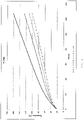
- the temperature change is then determined according to the method described above. The result of the measurement is shown in drawing 1, curve 2 (with PE).
- a PE from LyondellBasell ( ®Lupolen 1800S) is filled with 20% graphite (SC20O, Kropfmühl).
- the flowable PE is integrated onto the bobbin according to example 1, the weight of which has been previously determined, by the method of dipping or spraying and tempering according to example 2.
- the amount of PE that has penetrated the turns of the coil is determined.
- the mass is 4 g.
- the temperature change is measured according to the method described above. The result of the measurement is shown in drawing 1, curve 3 (PE + graphite).
- a PCM compound (OC.82, from Smartpolymer, melting point 82° C., 80% by mass of PCM in a TPE-S (Kuraray, ® Septon 4055) network is added to the coil Example 1, the weight of which was previously determined, integrated by the method of immersion or spraying and annealing as in Example 2.
- the amount of PCM compound that has penetrated the turns of the coil is measured.
- the mass is 4 g.
- the temperature change is measured according to the method described above. The result of the measurement is shown in drawing 1, curve 4 (with PCM 82°C).
- the temperature on the unfilled coil reaches a maximum temperature of 160°C. At even higher temperatures, the copper coil will be thermally damaged.
- the displacement of the air from the gap volume of the coil by the PE increases the thermal conductivity and the thermal mass.
- the PE serves as a sensitive heat accumulator and stores the resulting waste heat, a dampened rise in temperature takes place. Compared to windings without filling, a longer operating time of approx. 30% can be made possible until the maximum temperature is reached. With the same operating time, the maximum temperature can be reduced by approx. 18% (curve "with PE").
- the thermal mass and the thermal conductivity compared to air and PE without graphite increase from 0.3 to 0.9 W/m*K.
- the PE with graphite serves as a sensitive heat accumulator with increased thermal conductivity, which means that the waste heat is dissipated and stored more quickly, and there is a dampened rise in temperature.
- a longer operating time of approx. 55% can be made possible until the maximum temperature is reached. With the same operating time, the maximum temperature can be reduced by approx. 22%.
- the PCM 82°C serves as a latent heat accumulator with a storage capacity that is up to 2-4 times higher than that of PE and stores the waste heat produced, with a dampened rise in temperature taking place. Due to the phase change at 82°C, the resulting waste heat is used for the solid-liquid phase change, in which a multiple of energy can be stored in a small temperature range. By going through the phase change, a volume expansion takes place. This favors an adaptation of the PCM to the surface of the winding body, which also minimizes contact resistance and increases heat transfer. Compared to windings without filling (curve 1), a longer operating time of approx. 75% can be made possible until the maximum temperature is reached. With the same operating time, the maximum temperature can be reduced by approx. 30%. Compared to windings with PE filling (curve 2), a longer operating time of approx. 40% can be made possible until the maximum temperature is reached. With the same operating time, the maximum temperature can be reduced by approx. 15%.
Landscapes
- Engineering & Computer Science (AREA)
- Power Engineering (AREA)
- Chemical & Material Sciences (AREA)
- Physics & Mathematics (AREA)
- Spectroscopy & Molecular Physics (AREA)
- Organic Chemistry (AREA)
- Chemical Kinetics & Catalysis (AREA)
- Thermal Sciences (AREA)
- Materials Engineering (AREA)
- Combustion & Propulsion (AREA)
- Polymers & Plastics (AREA)
- Medicinal Chemistry (AREA)
- Health & Medical Sciences (AREA)
- Manufacturing & Machinery (AREA)
- Insulation, Fastening Of Motor, Generator Windings (AREA)
- Manufacture Of Motors, Generators (AREA)
- Professional, Industrial, Or Sporting Protective Garments (AREA)
- Thermistors And Varistors (AREA)
- Compositions Of Macromolecular Compounds (AREA)
Description
- Die Erfindung betrifft einen elektrischen Wickelkörper, der durch Tränken mit einem mit Phasenwechselmaterial gefüllten thermoplastischen Material verbesserte Gebrauchseigenschaften aufweist. Diese Gebrauchseigenschaften betreffen eine verbesserte Wärmeableitung, Vibrationsdämpfung, Fixierung der Wicklungen und einen verbesserten Schutz vor Überhitzung durch Ausnutzen der sensiblen und latenten Wärmespeichereigenschaften beim Übergang vom teilkristallinen Zustand der Polymereinheiten in den amorphen.
- Elektrische Wickelkörper umfassen Wicklungen, meist isolierte Kupferdrähte, die um einen Kern gewickelt sind. Der elektrische Wickelköper umfasst jegliche Art von Spulen in Form von Wicklungen und Wickelgüter, die geeignet sind ein Magnetfeld zu erzeugen oder zu detektieren. Diese Wickelkörper werden in elektrischen Betriebsmitteln wie Transformatoren, Wandlern, Rotoren und Statoren von elektrischen Maschinen eingesetzt. Es ist bekannt (
DE19928323 ), höher beanspruchte Wicklungen, die in Wickelkörpern verarbeitet sind, mit Kunstharzen zu imprägnieren um den Wirkungsgrad zu verbessern durch Minimieren der Verlustleistung. Die Idee dahinter ist, die luftgefüllten Hohlräume zwischen den Wicklungen durch ein Kunstharz zu ersetzen. Das Kunstharz hat eine höhere Wärmeleitfähigkeit als Luft, kann also beim Gebrauch entstehende Wärme besser ableiten. Zudem hat das Kunstharz auch eine höhere Dichte als Luft und kann so Unwuchten besser ausgleichen und Vibrationen verringern. Das Imprägnieren dient der Erhöhung der Isolationsfestigkeit und daneben auch der Fixierung der Wicklungen, der Verbesserung der Wärmeabfuhr aus dem Wickelkörper sowie dem Korrosionsschutz. Es werden Duroplaste verwendet, um die Hohlräume zwischen den Wicklungen zu füllen, da diese eine sehr gute Fließfähigkeit im flüssigen Zustand besitzen und dadurch leichter in die Hohlräume eindringen können und thermisch stabiler sind. Nachteil der Duroplaste ist, dass diese in einem zusätzlichen Arbeitsschritt ausgehärtet werden müssen und der Phasenübergang in die feste Phase irreversibel ist und die Werkstoffe nach der Aushärtung sehr spröde sind. Wenn es zu einer thermischen Überlastung kommt, können diese Materialien diese Überlast nicht ausgleichen oder abfedern und werden zerstört. Zu solch einer thermischen Überlastung kann es häufig bei elektrischen Wickelkörpern kommen, die immer nur kurzzeitig, d.h. im Bereich von Sekunden bis zu einigen Minuten (< 10 min), aber dafür wiederholt in mehr oder minder großen Abständen in Betrieb sind. Für solche Wickelkörper ist oft eine Temperaturregelung durch Anpassung der Stromstärke nicht vorgesehen bzw. nicht sinnvoll. -
US20130264896 beschreibt einen gegossenen Körper aus einem Stator bestehend aus Magnetspule auf einem Eisenkern, umhüllt mit einem Einspritzharz, welches ein Duroplastharz und ein mit diesem inkompatibles thermoplastisches Harz umfasst und welches anorganische Additive (Metallhydrate) enthält und eine Wärmeleitfähigkeit von ≥ 1,5 W/m . K und eine Flammfestigkeit nach UL94V-0 erfüllt. Die Menge an Metallhydrat ist ≥ 2 Anteilen an Gießharz. Ein gegossener Motor umfasst diesen gegossenen Körper. Aufgabe war es, einen Kunststoff als Isolator zu finden, der gleichzeitig niedrigen Schrumpf, hohe Wärmeleitfähigkeit und Flammfestigkeit bietet. Das Einspritzharz bildet eine Art Gehäuse für den Stator, die Art der Fertigung und die Zusammensetzung lassen es nicht zu, dass das Einspritzharz alle Luft zwischen den Wicklungen verdrängt, man erreicht ein verbessertes Wärmemanagement und eine Vibrationsstabilität, jedoch werden große Mengen an Einspritzharz benötigt und diese Art der Wicklungsumhüllung ist nur für Statoren geeignet. Zudem ist die Lösung in diesem Patent für eine Dauerbelastung der Spule ausgelegt, für eine kontinuierliche Abführung der Wärme durch ein hochwärmeleitfähiges Kunststoffgehäuse, das die Wärme an die Oberfläche abgibt. - Aus
US2004/056537A1 ist ein elektrischer Motor bekannt, dessen Wickelkörper mit einem thermoplastischen Kunststoff eingekapselt ist, der ein Phasenwechselmaterial enthält. Zwischen den Wicklungen befindet sich kein solcher Kunststoff, sondern ein wärmeaktivierbarer Klebstoff. - Aus
EP2637176A1 ist die Wicklung einer elektrischen Maschine bekannt, die mit einem Isoliermaterial umschlossen ist. Das Isolermaterial ist ein Gießharz, das ein Phasenwechselmaterial enthält. - Aus
US2006/124892A1 ,DE102013215255A1 undDE10329583A1 sind thermoplastische Elastomere mit zur Wärmeregulierung zugemischten Phasenwechselmaterialien bekannt. - Der Erfindung liegt die Aufgabe zugrunde, einen Wickelkörper, der in Transformatoren, Wandlern, Rotoren und Statoren von elektrischen Maschinen zum Einsatz kommt, zu schaffen, der eine verbesserte thermische Gesamtkapazität besitzt, das Auftreten von Hot Spots vermindert und bei thermischer Überlast ausgleichend wirken kann. Die Erfindung soll bei kurzzeitigen Belastungen (Kurzzeitbetrieb) wirken, es sollen Wärmespitzen abgefangen werden bei einem sehr geringen Materialeinsatz. Zudem soll die Erfindung bei Wicklungen sowohl für Statoren als auch für Rotoren zum Einsatz kommen.
- Diese Aufgabe wird erfindungsgemäß durch die Merkmale von Anspruch 1 gelöst. Alle Hohlräume zwischen den Wicklungen werden mit geringen Mengen an einem thermoplastischen Kunststoffmaterial (auch bezeichnet als Kompositwerkstoff oderCompound) ausfüllt, welcher ein Netzwerk aus einem thermoplastischen Elastomer (TPE) mit einem darin verteilten Phasenwechselmaterial (PCM) umfasst. Die thermoplastischen Elastomere sollten einen niedrigen Erweichungspunkt haben, der Zersetzungspunkt der Schmelze sollte bei einer Temperatur oberhalb der kritischen Gebrauchstemperatur der Wickelkörper von 180 °C liegen. Die thermoplastischen Elastomere weisen allgemein ein Glastemperatur Tg von weniger als 0 °C auf, jedoch keinen festen Schmelzpunkt. Das TPE besteht vorzugsweise aus einem Styrol-Blockcoplymer (TPE-S), welches durch seine polymere Netzwerkstruktur gekennzeichnet ist, in der das PCM physikalisch gebunden ist. Das TPE-S ist ausgewählt aus der Gruppe Styrol-Blockcopolymere wie Styrol-Butadien-Styrol (SBS), Styrol-Ethylen-Butylen-Styrol (SEBS), Styrol-Ethylen-Propylen-Styrol-Block-Copolymer (SEPS), Styrol-Ethylen-Ethylen-Propylen-Styrol-Block-Copolymer (SEEPS) und Methyl Butadien Styrol (MBS), kommerziell erhältlich z.B. unter den Bezeichnungen ®Kraton (Kraton Polymers), ®Septon (Kuraray), ®Styroflex (BASF), ®Thermolast (Kraiburg TPE) oder ®Saxomer (PCW). Besonders geeignet sind solche TPE-S, die eine niedrige Glasübergangstemperatur und sehr gute Fließfähigkeit (niedrige Viskosität) bei Temperaturen über 100 °C aufweisen. Es ist von Vorteil, wenn das TPE-PCM-Compound eine sehr gute Fließfähigkeit zeigt, das heißt einen Schmelzflussindex von mindestens 15 g/10 min (190 °C/2,16 kg, gemessen nach ISO 1133-1), besonders bevorzugt mindestens 20 g/10 min (190 °C/2,16 kg, gemessen nach ISO 1133-1). Die Masse TPE-S im späteren Compound sollte 10 Gew.-% nicht unterschreiten, bevorzugt liegt sie zwischen 15 und 25 Gew.-%.
- Die Verdrängung der Luft aus den Hohlräumen zwischen den Wicklungen erfolgt hauptsächlich durch die Wirkung von Kapillarkräften, durch die das thermoplastische Material in diese Hohlräume "gesaugt" wird. Damit das thermoplastische Kunststoffmaterial bis in das Innerste der Wicklung vordringen kann und nicht irgendwo Hohlräume verbleiben, in denen später Teilentladungen auftreten könnten, wird nicht nur die thermoplastische Kunststoffmasse erwärmt, sondern auch das Wickelgut auf eine Temperatur deutlich oberhalb der Wärmeformbeständigkeitstemperatur des TPE-PCM-Compounds nach DIN EN ISO 75-1,-2,-3 vorgewärmt, meist auf Temperaturen zwischen 100 und 150 °C. Ohne eine solche Vorwärmung käme es im Wickelgut frühzeitig zu Erstarrungsvorgängen und das bereits erstarrte PCM-Compound würde das Eindringen weiteren PCM-Compounds verhindern. Diese Erwärmung kann erfolgen, indem das Wickelgut in einem Ofen platziert wird oder elektrischer Strom angelegt wird. Die letztgenannte Methode hat den Vorteil, dass die Energiezufuhr auch während des Tränkens aufrechterhalten werden kann. Die Kapillarkräfte bewirken zusammen mit Adhäsionskräften gleichzeitig auch, dass das Material bei Erweichung nicht sofort wieder austritt und "ausblutet", denn bei den Arbeitstemperaturen des Wickelkörpers oberhalb von 100 °C liegt das TPE-PCM Compound immer in fließfähiger Form vor.
- Die Verwendung von mit Phasenwechselmaterialien gefüllten Compunds als Füllmaterial hat zudem den Vorteil, dass bei Gebrauch, nach dem Anlegen von Strom, das Phasenwechselmaterial von der festen in die flüssige Phase übergeht und dabei gleichzeitig sich das Volumen ausdehnt. Das erklärt die Beobachtung, dass der Wärmeregulierungseffekt nach dem ersten Gebrauch sich noch verbessert, da durch die Volumenzunahme weitere Luft aus den Hohlräumen zwischen den Wicklungen verdrängt wird.
- Eine Methode zum Befüllen der Hohlräume zwischen den Wicklungen des elektrischen Wickelkörpers kann darin bestehen, dass das thermoplastische Material in einer Tauchvorrichtung mittels Heizplatte erhitzt wird, beispielsweise auf eine Verarbeitungstemperatur von 170°C. Zur Erzielung einer homogenen Masse wird das thermoplastische Material gerührt. Der Wickelkörper wird im Ofen 30 min lang auf beispielsweise 120°C vorgewärmt. Nach Temperaturangleich der Schmelze des thermoplastischen Materials mit der Temperatur des Tauchwerkzeugs wird der vorgeheizte Wickelkörper senkrecht in die Tauchvorrichtung gedrückt und unter minimalen Kraftaufwand füllt sich vollständig das Lückenvolumen des Wickelkörpers. Danach wird der Wickelkörper aus der Tauchvorrichtung herausgezogen und auf Raumtemperatur abgekühlt. Beim Herausnehmen aus dem Tauchbad tropft TPE-PCM-Compoundmasse, die nicht in die Wicklungen eingedrungen ist, ab. Bei Bedarf, das hängt vom Wickelkörper ab, wird überschüssiges thermoplastisches Material außerhalb der Wicklungen abgetragen. Danach erfolgt ein Tempern des getauchten Wickelkörpers im Ofen, z.B. im vorgeheizten Ofen für 2h bei 120°C. Auch bei diesem Schritt kann überschüssiges TPE-PCM-Compoundmaterial noch abtropfen. Durch die Wärmebehandlungen werden die Kupferwicklungen formschlüssig mit dem polymeren Füllmaterial bedeckt. Danach wird der Wickelkörper wieder auf Raumtemperatur abgekühlt.
- Man kann den TPE-PCM Compound auch durch Besprühen oder Bestreichen des vorgewärmten Wickelkörpers mit dem erwärmten TPE-PCM-Compound aufbringen. Dabei wurde beobachtet, dass zum Beispiel nach dem Bestreichen und der anschließenden Temperung oberflächlich auf den Wicklungen kein TPE-PCM-Compound mehr zu sehen ist, d.h. an diesen Stellen die Masse durch die Kapillarkräfte aufgesogen wurde. Nur an weiteren Hohlräumen oder Nuten an der Oberfläche, wo die Kapillarkräfte nicht wirken, befinden sich noch geringe Mengen an TPE-PCM-Compound. Auf diese Weise werden nur sehr geringe Mengen an Füllmasse benötigt um Wärmespitzen bei Kurzzeitbelastung zu vermeiden.
- Auf diese Weise kann diese Art der Thermoregulierung des Wickelgutes auch für Rotorwicklungen angewendet werden, allerdings ist in diesen Fällen eine dünne zusätzliche äußere Schutzschicht (Versiegelung) notwendig, die das thermoplastische Füllmaterial während des Gebrauchs im Rotor hält. Das kann eine Schutzschicht bestehend aus PE, PP, PA, PMMA, PS, PVC mit einer Dicke von 100 bis500 µm sein, aufgebracht mittels Gießen, Tauchen, Sprühen oder Spritzguss.
- Eine andere Ausführungsform ist die Verwendung einer Spritz- oder Fördervorrichtung z.B. einer Heißklebepistole zur Befüllung des Lückenvolumens. Mittels mechanischen / hydraulischen / pneumatischen Drucks wird das aufgeschmolzene TPE-PCM-Compound in das Lückenvolumen des Wickelkörpers gespritzt oder es umhüllt ihn vollständig. Danach erfolgt ein Tempern des getauchten Wickelkörpers im Ofen, z.B. im vorgeheizten Ofen für 2h bei 120°C. Dadurch wird zusätzlich ein Eindringen des PCM-Compounds in die Wicklungskapillare unterstützt. Als thermoplastisches Material kommen alle thermoplastischen Kunststoffe in Frage, die die oben genannten Bedingungen bezüglich Schmelzpunkt und Fließfähigkeit erfüllen und gleichzeitig ein Netzwerk zur Bindung von Phasenwechselmaterialien ausbilden können. Es handelt sich dabei bevorzugt um thermoplastische Elastomere, insbesondere Styrol-Blockcopolymere (TPE-S). Den thermoplastischen Materialien können neben den Phasenwechselmaterialien weitere Additive von bis zu 20 Gew.-% zugesetzt werden wie elektrisch nicht-leitfähige Materialien bzw. auch leitfähige Materialien in Anteilen unterhalb der Perkolationsschwelle, Additive, die die Wärmeleitfähigkeit erhöhen, nicht-magnetische Materialien, die die Dichte erhöhen, Flammschutzmittel, die das Brandverhalten bei Überlast, insbesondere des Cu-Lack-Drahtes positiv beeinflussen, Agentien, die das Fließverhalten beeinflussen.
- Der Mengenanteil dieser Additive an der thermoplastischen Kunststoffmasse kann zwischen 0 bis 20 Gew.-% liegen.
- Den thermoplastischen Elastomeren, die ein polymeres Netzwerk für Phasenwechselmaterialien bilden, werden bevorzugt zwischen 75 bis 85 Gew.-% Phasenwechselmaterialien zugesetzt, um eine optimale Wirkung zu erzielen. Die Phasenübergangs- (Schmelz-)temperatur der Phasenwechselmaterialien wird der Gebrauchstemperatur der Wickelkörper angepasst. Sie darf nicht zu niedrig gewählt werden, dann kann der Effekt der Wärmespeicherung während des Schmelzens nicht ausgenutzt werden und die Temperatur der gefüllten Wickelkörper entwickelt sich ähnlich der Temperaturkurve einer Wickelfüllung mit ungefüllten Kunststoffmassen.
- Ein zu niedrigerer Schmelzpunkt(< 60°C) gegenüber der Arbeitstemperatur hat zur Folge, dass bei Normalbelastung der Spule bereits Grundtemperaturen vorliegen, die größer als die Schmelztemperatur des PCMs ist (beispielsweise bei einer PCM-Füllung mit einer Schmelztemperatur von 42°C). Somit hat die latente Wärmspeicherung keinen Einfluss mehr und nur noch der sensible Anteil steht zur Aufnahme der Abwärme bereit. Die maximale Arbeitstemperatur bestimmt die Auswahl des PCM-Schmelzpunkts. Bei einer Arbeitstemperatur, die nicht größer als 80°C ist, wird beispielsweise ein PCM mit einem Schmelzpunkt von 62°C ausgewählt.
- Als Phasenwechselmaterial eignen sich Dialkylether mit langkettigen Alkylresten, n-Alkane, ein- oder mehrwertige Alkohole (z.B. Polyethylenglykol), PE-Wachs, jeweils mit Schmelztemperaturen im Bereich von 40 bis 140°C und bevorzugt zwischen 80 und130°C. Als "Dialkylether mit langkettigen Alkylresten" werden dabei solche bezeichnet, die in beiden Alkylresten zusammen mindestens 28 Kohlenstoffatome aufweisen. Das sind beispielsweise: Di-n-myristyl-ether (Schmelzpunkt 44 °C), Di-n-cetyl-ethern (Schmelzpunkt 54 °C) oder Di-n-stearyl-ether (Schmelzpunkt 62 °C), erhältlich unter der Bezeichnung ®Nacol ether 14, ®Nacol ether 16 bzw. ®Nacol ether 18 von Sasol. Bei polymeren Phasenwechselmaterialien beträgt das Molekulargewicht allgemein 100.000 g/mol oder weniger, bevorzugt 30.000 g/mol oder weniger. Der Wärmeregulierungseffekt hängt zum einen vom Anteil PCM im Füllmaterial und von der Menge an polymerem Füllmaterial zwischen den Wicklungen ab.
- Treten während des Betriebes der Wickelkörper Überhitzungen auf, so nimmt das thermoplastische Material überschüssige Wärme auf, sowohl sensible Wärme als auch latente beim Übergang von einem teilkristallinen in einen amorphen Zustand und leitet diese aufgrund der guten Wärmeleitfähigkeit von über 0,2 W/mK weiter an Kühleinrichtungen. Durch die latente Wärmespeicherung können Schäden durch Überhitzung vermieden werden bzw. wird deren Eintritt verzögert.
- Vorteilhalterweise werden die erfindungsgemäßen Wickelkörper eingesetzt in Anwendungen, wo diese Wickelkörper immer nur kurzzeitig, d.h. im Bereich von Sekunden bis zu einigen Minuten (< 10 min), aber dafür wiederholt in mehr oder minder großen Abständen in Betrieb sind. Beispiele dafür sind Fensterheber, elektrische Türöffner, Bedienung von Jalousien und ähnliche.
- Die Temperaturbestimmung eines Wickelkörpers (3) erfolgt über die Messung des widerstandsabhängigen Spannungsabfalls, der direkt am Kommutator über einen Zeitraum von 2min in einem Zeitabstand von 1 s geloggt wird. Mit dem Labornetzgerät Manson HCS-3202 (1) wird ein elektrischer Strom von 8A in die Wicklung eingespeist. Mit dem Data Logger C-122 (2) wird im Sekundenabstand der temperaturabhängige Spannungsabfall gemessen. Netzgerät (1), Data Logger (2) und Wickelkörper (3) sind in einem Schaltkreis parallel geschaltet. Die Berechnung der Temperatur wurde mit folgender Gleichung durchgeführt:

- An einem handelsüblichen Wickelkörper mit Kupferwicklungen, Durchmesser Cu-Draht 0,5mm, Länge 15m, ohne integrierte Füllung wird nach der oben genannten Messmethode die temperaturabhängige Widerstandsänderung gemessen und die Temperatur berechnet. Das Ergebnis der Messung ist in Zeichnung 1, Kurve 1 (ohne Füllung) dargestellt. Diese Kurve dient Vergleichs-zwecken.
- Ein fließfähiges PE der Firma LyondellBasell (®Lupolen 1800S) wird auf die Spule nach Beispiel 1, deren Gewicht vorher bestimmt wurde, durch die Methode Tauchen oder Spritzen integriert. Dazu wird die Spule vor dem Füllen auf eine Temperatur von 120°C erwärmt und nach dem Füllen in einer Wärmekammer bei 140 °C 30 min gehalten und anschließend auf Raumtemperatur abgekühlt. Dadurch werden die Kupferwicklungen und alle Hohlräume in den Wicklungen formschlüssig mit dem PE bedeckt. Durch Messen des Gewichts der Spule nach dem Tauchen oder Spritzen wird die Menge PE, die in die Windungen der Spule eingedrungen ist, bestimmt. Die Masse beträgt 4 g. Dann erfolgt die Bestimmung der Temperaturänderung nach dem oben beschriebenen Verfahren. Das Ergebnis der Messung ist in Zeichnung 1, Kurve 2 (mit PE) dargestellt.
- Ein PE der Firma LyondellBasell (®Lupolen 1800S) wird mit 20% Graphit (SC20O, Fa. Kropfmühl) gefüllt. Das fließfähige PE wird auf die Spule nach Beispiel 1, deren Gewicht vorher bestimmt wurde, durch die Methode Tauchen oder Spritzen und Tempern entsprechend Beispiel 2 integriert. Durch Messen des Gewichts der Spule nach dem Tauchen oder Spritzen wird die Menge PE, die in die Windungen der Spule eingedrungen ist, bestimmt. Die Masse beträgt 4 g. Dann erfolgt die Messung der Temperaturänderung nach dem oben beschriebenen Verfahren. Das Ergebnis der Messung ist in Zeichnung 1, Kurve 3 (PE + Graphit) dargestellt.
- Ein PCM-Compound (OC.82, Fa. Smartpolymer, Schmelzpunkt 82 °C, 80 Ma.-% PCM in einem TPE-S (Kuraray, ®Septon 4055) Netzwerk wird auf die Spule nach Beispiel 1, deren Gewicht vorher bestimmt wurde, durch die Methode Tauchen oder Spritzen und Tempern entsprechend Beispiel 2 integriert. Durch Messen des Gewichts der Spule nach diesem Vorgang wird die Menge PCM-Compound, die in die Windungen der Spule eingedrungen ist, gemessen. Die Masse beträgt 4 g. Dann erfolgt die Messung der Temperaturänderung nach dem oben beschriebenen Verfahren. Das Ergebnis der Messung ist in Zeichnung 1, Kurve 4 (mit PCM 82°C) dargestellt.
- Auswertung der Versuchsergebnisse, dargestellt in Zeichnung 1:
- Nach einer Betriebszeit von 120s erreicht die Temperatur an der ungefüllten Spule eine Maximaltemperatur von 160°C. Bei noch höheren Temperaturen kommt es zur thermischen Schädigung der Cu-Spule.
- Durch die Verdrängung der Luft aus dem Lückenvolumen der Spule durch das PE erhöhen sich die Wärmeleitfähigkeit sowie die thermische Masse. Das PE dient als sensibler Wärmespeicher und speichert die entstehende Abwärme, ein gedämpfter Temperaturanstieg findet statt. Gegenüber Wicklungen ohne Füllung kann eine längere Betriebszeit von ca. 30% ermöglicht werden bis die Maximaltemperatur erreicht ist. Bei gleicher Betriebszeit kann die Maximaltemperatur um ca. 18% gesenkt werden (Kurve "mit PE").
- Durch die Verdrängung der Luft aus dem Lückenvolumen der Spule durch PE mit Graphit erhöhen sich die thermische Masse sowie die Wärmeleitfähigkeit gegenüber Luft sowie PE ohne Graphit von 0,3 auf 0,9W/m*K. Das PE mit Graphit dient als sensibler Wärmespeicher mit erhöhter Wärmeleitfähigkeit wodurch die Abwärme schneller abgeführt und gespeichert wird, ein gedämpfter Temperaturanstieg findet statt. Gegenüber Wicklungen ohne Füllung kann eine längere Betriebszeit von ca. 55% ermöglicht werden bis die Maximaltemperatur erreicht ist. Bei gleicher Betriebszeit kann die Maximaltemperatur um ca. 22% gesenkt werden.
- Durch die Verdrängung der Luft aus dem Lückenvolumen der Spule durch das Kunststoffgemisch TPE-S mit PCM 82°C (Kurve 4) erhöht sich die Wärmeleitfähigkeit sowie die thermische Masse. Durch das sehr gute Fließverhalten ist das TPE-PCM-Compound optimal zwischen die Windungen eingedrungen wodurch die Wärmeübergänge erhöht wurden. Fast gleichzeitig setzt auch der Effekt der latenten Wärmespeicherung ein, siehe hierzu als Vergleich den Kurvenverlauf ohne Füllung, schon nach 40sec haben die Windungen 80°C erreicht, während bei Füllung mit dem TPE_PCM Compound 80 °C erst nach ca. 95 s erreicht werden. Deshalb ist der Anstieg dieser Kurve schon sehr früh niedriger als bei den anderen Kurven. Das PCM 82°C dient als latenter Wärmespeicher mit bis zu 2-4fach höherer Speicherkapazität gegenüber PE und speichert die entstehende Abwärme, ein gedämpfter Temperaturanstieg findet statt. Auf Grund des Phasenwechsels bei 82°C wird die entstehende Abwärme zur Phasenumwandlung fest-flüssig genutzt, bei der in einem kleinen Temperaturbereich ein Vielfaches an Energie gespeichert werden kann. Durch das Durchschreiten des Phasenwechsels findet eine Volumenausdehnung statt. Diese begünstigt eine Anpassung des PCMs an die Oberfläche des Wickelkörpers, wodurch Übergangswiderstände zusätzlich minimiert werden und die Wärmeübertragung erhöht wird. Gegenüber Wicklungen ohne Füllung (Kurve 1) kann eine längere Betriebszeit von ca. 75% ermöglicht werden bis die Maximaltemperatur erreicht ist. Bei gleicher Betriebszeit kann die Maximaltemperatur um ca. 30% gesenkt werden. Gegenüber Wicklungen mit PE Füllung (Kurve 2) kann eine längere Betriebszeit von ca. 40% ermöglicht werden bis die Maximaltemperatur erreicht ist. Bei gleicher Betriebszeit kann die Maximaltemperatur um ca. 15% gesenkt werden.
- Gegenüber Wicklungen mit PE und Graphit Füllung (Kurve 3) kann eine längere Betriebszeit von ca. 20% ermöglicht werden bis die Maximaltemperatur erreicht ist. Bei gleicher Betriebszeit kann die Maximaltemperatur um 8% gesenkt werden.
Claims (11)
- Elektrischer Wickelkörper, umfassend elektrisch leitfähige Wicklungen um einen Kern, wobei die Hohlräume zwischen den Wicklungen durch ein thermoplastisches Kunststoffmaterial formschlüssig ausgefüllt sind, wobei das thermoplastische Kunststoffmaterial eine Mischung ausa) einem netzwerkbildenden thermoplastischen Elastomer, das im Bereich von 120 - 150 °C eine sehr gute Fließfähigkeit und einen Schmelzflussindex von mindestens 15 g/10 min (190 °C/2,16 kg, gemessen nach ISO 1133-1) aufweist undb) einem Phasenwechselmaterial mit einer Phasenwechseltemperatur, die zwischen 40 °C und 140 °C liegt, umfasst, wobei das Phasenwechselmaterial in dem thermoplastischen Kunststoffmaterial in einem Anteil von 50 bis 85 Gew.-% enthalten ist.
- Wickelkörper nach Anspruch 1, dadurch gekennzeichnet, dass das netzwerkbildende thermoplastische Elastomer ein styrolhaltiges Block-Copolymer ist, bevorzugt Styrol/Butadien/Styrol (SBS), SEBS, SEPS, SEEPS und MBS, und in einem Anteil von mindestens 10 Gew.-% vorliegt, bevorzugt zwischen 15 Gew.-% bis 25 Gew.-%, bezogen auf das Gewicht des Kunststoffmaterials.
- Wickelkörper nach Anspruch 1 oder 2, dadurch gekennzeichnet, dass das Phasenwechselmaterial eine Schmelztemperatur zwischen 40 °C und 140 °C aufweist und bevorzugt ein Alkoholether, ein Dialkylether, ein Paraffin oder ein natürliches oder synthetisches Wachs ist.
- Elektrischer Wickelkörper nach einem oder mehreren der Ansprüche 1 bis 3, dadurch gekennzeichnet, dass die Zersetzungstemperatur des thermoplastischen Kunststoffmaterials oberhalb der kritischen Gebrauchstemperatur des elektrischen Wickelkörpers liegt.
- Elektrischer Wickelkörper nach einem oder mehreren der Ansprüche 1 bis 4, dadurch gekennzeichnet, dass das Phasenwechselmaterial in dem thermoplastischen Kunststoffmaterial in einem Anteil von 70 bis 85 Gew.-% enthalten ist.
- Elektrischer Wickelkörper nach einem oder mehreren der Ansprüche 1 bis 5, dadurch gekennzeichnet, dass das thermoplastische Kunststoffmaterial funktionelle Additive enthält, die die Wärmeleitfähigkeit erhöhen, die die Dichte erhöhen, die das Fließverhalten der Schmelze beeinflussen und/oder als Flammschutzmittel wirken.
- Elektrischer Wickelkörper nach Anspruch 6, dadurch gekennzeichnet, dass der Anteil der funktionellen Additive 0 bis 20 Gew.-% beträgt, bezogen auf das Gesamtgewicht des thermoplastischen Kunststoffmaterials.
- Elektrischer Wickelkörper nach einem oder mehreren der Ansprüche 1 bis 7, dadurch gekennzeichnet, dass er von einer äußeren Schutzschicht umgeben ist, die das thermoplastische Kunststoffmaterial auch bei Anwendung für Rotorwicklungen im Wickelkörper hält, wobei die Schutzschicht bevorzugt aus PE, PP, PA, PMMA, PS oder PVC besteht und bevorzugt eine Dicke von 100 bis500 µm aufweist.
- Elektrischer Wickelkörper nach einem oder mehreren der Ansprüche 1 bis 8, dadurch gekennzeichnet, dass er Bestandteil eines Transformators, eines Wandlers oder eines Rotors oder Stators einer elektrischen Maschine ist, wo diese Wickelkörper nur dazu geeignet sind, immer nur kurzzeitig, d.h. im Bereich von Sekunden bis zu 10 Minuten, dafür wiederholt in mehr oder minder großen Abständen in Betrieb zu sein.
- Elektrischer Wickelkörper nach einem oder mehreren der Ansprüche 1 bis 9, dadurch gekennzeichnet, dass das netzwerkbildende thermoplastische Elastomer einen Schmelzflussindex von mindestens 20 g/10 min (190 °C/2,16 kg, gemessen nach ISO 1133-1) aufweist.
- Elektrischer Wickelkörper nach einem oder mehreren der Ansprüche 1 bis 10, dadurch gekennzeichnet, dass das Phasenwechselmaterial eine Phasenwechseltemperatur zwischen 80 und 130 °C aufweist.
Applications Claiming Priority (2)
| Application Number | Priority Date | Filing Date | Title |
|---|---|---|---|
| DE102017001547 | 2017-02-17 | ||
| PCT/EP2018/053945 WO2018150000A1 (de) | 2017-02-17 | 2018-02-16 | Elektrischer wickelkörper mit optimierten gebrauchseigenschaften und verbessertem schutz gegen überhitzung |
Publications (2)
| Publication Number | Publication Date |
|---|---|
| EP3583614A1 EP3583614A1 (de) | 2019-12-25 |
| EP3583614B1 true EP3583614B1 (de) | 2022-05-04 |
Family
ID=61581238
Family Applications (1)
| Application Number | Title | Priority Date | Filing Date |
|---|---|---|---|
| EP18709276.2A Active EP3583614B1 (de) | 2017-02-17 | 2018-02-16 | Elektrischer wickelkörper mit optimierten gebrauchseigenschaften und verbessertem schutz gegen überhitzung |
Country Status (7)
| Country | Link |
|---|---|
| US (1) | US11508504B2 (de) |
| EP (1) | EP3583614B1 (de) |
| CN (1) | CN110301017B (de) |
| DE (1) | DE102018103562A1 (de) |
| DK (1) | DK3583614T3 (de) |
| ES (1) | ES2919276T3 (de) |
| WO (1) | WO2018150000A1 (de) |
Families Citing this family (2)
| Publication number | Priority date | Publication date | Assignee | Title |
|---|---|---|---|---|
| CN111181285A (zh) * | 2020-02-05 | 2020-05-19 | 湖北工业大学 | 一种电机定子绕组的冷却方法 |
| EP3872962A1 (de) * | 2020-02-25 | 2021-09-01 | Siemens Aktiengesellschaft | Verfahren zum imprägnieren, verfestigen oder elektroisolieren eines ein- oder mehrlagige wicklungen tragenden körpers |
Family Cites Families (15)
| Publication number | Priority date | Publication date | Assignee | Title |
|---|---|---|---|---|
| US4199743A (en) | 1978-02-06 | 1980-04-22 | Westinghouse Electric Corp. | Encapsulated current transformer |
| US5589808A (en) | 1993-07-28 | 1996-12-31 | Cooper Industries, Inc. | Encapsulated transformer |
| WO1998053467A1 (en) * | 1997-05-23 | 1998-11-26 | Hitachi, Ltd. | Ignition coil unit for engine and engine provided with plastic head cover |
| DE19923201A1 (de) * | 1999-05-20 | 2000-11-23 | Mannesmann Vdo Ag | Für einen Einsatz in einem aggressiven Medium vorgesehener Einsatz |
| DE19928323A1 (de) | 1999-06-16 | 2000-12-21 | Siemens Ag | Verfahren zum Imprägnieren von elektrischem Wickelgut |
| US6946758B2 (en) | 2001-01-09 | 2005-09-20 | Black & Decker Inc. | Dynamoelectric machine having encapsulated coil structure with one or more of phase change additives, insert molded features and insulated pinion |
| JP2005533475A (ja) * | 2002-07-12 | 2005-11-04 | ブラック アンド デッカー インク | 封入コイル構造を有するダイナモエレクトリック機械 |
| DE10329583A1 (de) | 2003-06-30 | 2005-02-03 | Behr Gmbh & Co. Kg | Werkstoff für Formteile |
| CN101115817B (zh) * | 2004-12-09 | 2013-09-18 | 纳幕尔杜邦公司 | 用于热量管理的相变材料(pcm)组合物 |
| CN101117572B (zh) * | 2007-07-25 | 2011-05-11 | 中南大学 | 以凝胶为载体的复合相变蓄热材料及其制备方法 |
| EP2196500B1 (de) * | 2008-12-12 | 2013-04-10 | Cheil Industries Inc. | Thermoplastische Elastomerzusammensetzung |
| US20130264896A1 (en) | 2010-12-17 | 2013-10-10 | Panasonic Corporation | Molded structural body and motor having same |
| ES2562188T3 (es) | 2012-03-07 | 2016-03-02 | Siemens Aktiengesellschaft | Transformador encapsulado en resina |
| KR101727377B1 (ko) | 2012-11-30 | 2017-04-14 | 후루카와 덴키 고교 가부시키가이샤 | 절연 전선 및 전기·전자기기 |
| DE102013215255A1 (de) * | 2013-08-02 | 2015-02-05 | Siemens Aktiengesellschaft | Elektronisches oder elektrisches Bauteil mit PCM-haltiger Kühlung |
-
2018
- 2018-02-16 WO PCT/EP2018/053945 patent/WO2018150000A1/de not_active Ceased
- 2018-02-16 DE DE102018103562.4A patent/DE102018103562A1/de not_active Withdrawn
- 2018-02-16 CN CN201880012080.9A patent/CN110301017B/zh active Active
- 2018-02-16 ES ES18709276T patent/ES2919276T3/es active Active
- 2018-02-16 US US16/485,745 patent/US11508504B2/en active Active
- 2018-02-16 EP EP18709276.2A patent/EP3583614B1/de active Active
- 2018-02-16 DK DK18709276.2T patent/DK3583614T3/da active
Also Published As
| Publication number | Publication date |
|---|---|
| WO2018150000A4 (de) | 2018-10-18 |
| US11508504B2 (en) | 2022-11-22 |
| CN110301017B (zh) | 2021-11-05 |
| DK3583614T3 (da) | 2022-06-20 |
| US20200005976A1 (en) | 2020-01-02 |
| DE102018103562A1 (de) | 2018-08-23 |
| ES2919276T3 (es) | 2022-07-22 |
| WO2018150000A1 (de) | 2018-08-23 |
| EP3583614A1 (de) | 2019-12-25 |
| CN110301017A (zh) | 2019-10-01 |
Similar Documents
| Publication | Publication Date | Title |
|---|---|---|
| JP4922018B2 (ja) | 回転電機のコイル絶縁物 | |
| Wrobel et al. | Characterizing the in situ thermal behavior of selected electrical machine insulation and impregnation materials | |
| DE2506790A1 (de) | Kern- und spulen-struktur fuer dynamomaschinen und verfahren zur herstellung derselben | |
| WO2015095271A1 (en) | Flexible phase change material composite for thermal management systems | |
| Ishibe et al. | A new concept varistor with epoxy/microvaristor composite | |
| WO2005057590A1 (de) | Metall-kunststoff-hybrid und daraus hergestellter formkörper | |
| DE102013104930A1 (de) | Wärmeleitende Beschichtung für Permanentmagnete in einer elektrischen Maschine | |
| EP2637176A1 (de) | Elektrische Wicklung | |
| DE102018103562A1 (de) | Elektrischer Wickelkörper mit optimierten Gebrauchseigenschaften und verbessertem Schutz gegen Überhitzung | |
| CN102055266B (zh) | 多胶模压绝缘体系定子线棒高导热绝缘结构 | |
| Yamanaka et al. | The development of DC+/-500 kV XLPE cable in consideration of the space charge accumulation | |
| EP4362048A1 (de) | Formulierung für ein isolationssystem, verwendung dazu und formkörper | |
| US6524710B1 (en) | Method for producing insulating tapes containing mica, and the utilization thereof | |
| Sathyamoorthy et al. | Experimental investigations on breakdown in cable insulation | |
| DE102021201666A1 (de) | Nutisolationssystem für eine elektrische rotierende Maschine, Verfahren zur Herstellung eines Nutisolationssystems | |
| DE102020133638A1 (de) | Elektrische Maschine mit einem Phasenwechselmaterial zum Verlängern eines Überlastbetriebs und Kraftfahrzeug | |
| EP3593361B1 (de) | Glimmschutzband für elektrische hochspannungsmaschine | |
| DE102010005020B4 (de) | Verwendung eines Formkörpers aus einem wärmeleitenden Kompositmaterial zur Wärmeableitung | |
| WO2009077088A2 (de) | Stator-gehäuse-einheit und verfahren zum herstellen derselben, sowie lackmaterial | |
| EP3544032B1 (de) | Transformator mit gel-verbundisolierung | |
| WO2016066346A1 (de) | Metall- und kunststoff-beschichtete batterie mit kunststoffgehäuse | |
| JP2010166809A (ja) | 回転電機 | |
| EP2797211B1 (de) | Elektrische Maschine sowie Verfahren zur Herstellung einer elektrischen Maschine | |
| CN110114839A (zh) | 电力电缆 | |
| DE102004034550A1 (de) | Glimmschutzband |
Legal Events
| Date | Code | Title | Description |
|---|---|---|---|
| STAA | Information on the status of an ep patent application or granted ep patent |
Free format text: STATUS: UNKNOWN |
|
| STAA | Information on the status of an ep patent application or granted ep patent |
Free format text: STATUS: THE INTERNATIONAL PUBLICATION HAS BEEN MADE |
|
| PUAI | Public reference made under article 153(3) epc to a published international application that has entered the european phase |
Free format text: ORIGINAL CODE: 0009012 |
|
| STAA | Information on the status of an ep patent application or granted ep patent |
Free format text: STATUS: REQUEST FOR EXAMINATION WAS MADE |
|
| 17P | Request for examination filed |
Effective date: 20190910 |
|
| AK | Designated contracting states |
Kind code of ref document: A1 Designated state(s): AL AT BE BG CH CY CZ DE DK EE ES FI FR GB GR HR HU IE IS IT LI LT LU LV MC MK MT NL NO PL PT RO RS SE SI SK SM TR |
|
| AX | Request for extension of the european patent |
Extension state: BA ME |
|
| DAV | Request for validation of the european patent (deleted) | ||
| DAX | Request for extension of the european patent (deleted) | ||
| GRAP | Despatch of communication of intention to grant a patent |
Free format text: ORIGINAL CODE: EPIDOSNIGR1 |
|
| STAA | Information on the status of an ep patent application or granted ep patent |
Free format text: STATUS: GRANT OF PATENT IS INTENDED |
|
| INTG | Intention to grant announced |
Effective date: 20211123 |
|
| GRAS | Grant fee paid |
Free format text: ORIGINAL CODE: EPIDOSNIGR3 |
|
| GRAA | (expected) grant |
Free format text: ORIGINAL CODE: 0009210 |
|
| STAA | Information on the status of an ep patent application or granted ep patent |
Free format text: STATUS: THE PATENT HAS BEEN GRANTED |
|
| AK | Designated contracting states |
Kind code of ref document: B1 Designated state(s): AL AT BE BG CH CY CZ DE DK EE ES FI FR GB GR HR HU IE IS IT LI LT LU LV MC MK MT NL NO PL PT RO RS SE SI SK SM TR |
|
| REG | Reference to a national code |
Ref country code: GB Ref legal event code: FG4D Free format text: NOT ENGLISH |
|
| REG | Reference to a national code |
Ref country code: CH Ref legal event code: EP |
|
| REG | Reference to a national code |
Ref country code: AT Ref legal event code: REF Ref document number: 1490002 Country of ref document: AT Kind code of ref document: T Effective date: 20220515 |
|
| REG | Reference to a national code |
Ref country code: DE Ref legal event code: R096 Ref document number: 502018009563 Country of ref document: DE |
|
| REG | Reference to a national code |
Ref country code: IE Ref legal event code: FG4D Free format text: LANGUAGE OF EP DOCUMENT: GERMAN |
|
| REG | Reference to a national code |
Ref country code: DK Ref legal event code: T3 Effective date: 20220616 |
|
| REG | Reference to a national code |
Ref country code: ES Ref legal event code: FG2A Ref document number: 2919276 Country of ref document: ES Kind code of ref document: T3 Effective date: 20220722 |
|
| REG | Reference to a national code |
Ref country code: LT Ref legal event code: MG9D |
|
| REG | Reference to a national code |
Ref country code: NL Ref legal event code: MP Effective date: 20220504 |
|
| PG25 | Lapsed in a contracting state [announced via postgrant information from national office to epo] |
Ref country code: SE Free format text: LAPSE BECAUSE OF FAILURE TO SUBMIT A TRANSLATION OF THE DESCRIPTION OR TO PAY THE FEE WITHIN THE PRESCRIBED TIME-LIMIT Effective date: 20220504 Ref country code: PT Free format text: LAPSE BECAUSE OF FAILURE TO SUBMIT A TRANSLATION OF THE DESCRIPTION OR TO PAY THE FEE WITHIN THE PRESCRIBED TIME-LIMIT Effective date: 20220905 Ref country code: NO Free format text: LAPSE BECAUSE OF FAILURE TO SUBMIT A TRANSLATION OF THE DESCRIPTION OR TO PAY THE FEE WITHIN THE PRESCRIBED TIME-LIMIT Effective date: 20220804 Ref country code: NL Free format text: LAPSE BECAUSE OF FAILURE TO SUBMIT A TRANSLATION OF THE DESCRIPTION OR TO PAY THE FEE WITHIN THE PRESCRIBED TIME-LIMIT Effective date: 20220504 Ref country code: LT Free format text: LAPSE BECAUSE OF FAILURE TO SUBMIT A TRANSLATION OF THE DESCRIPTION OR TO PAY THE FEE WITHIN THE PRESCRIBED TIME-LIMIT Effective date: 20220504 Ref country code: HR Free format text: LAPSE BECAUSE OF FAILURE TO SUBMIT A TRANSLATION OF THE DESCRIPTION OR TO PAY THE FEE WITHIN THE PRESCRIBED TIME-LIMIT Effective date: 20220504 Ref country code: GR Free format text: LAPSE BECAUSE OF FAILURE TO SUBMIT A TRANSLATION OF THE DESCRIPTION OR TO PAY THE FEE WITHIN THE PRESCRIBED TIME-LIMIT Effective date: 20220805 Ref country code: FI Free format text: LAPSE BECAUSE OF FAILURE TO SUBMIT A TRANSLATION OF THE DESCRIPTION OR TO PAY THE FEE WITHIN THE PRESCRIBED TIME-LIMIT Effective date: 20220504 Ref country code: BG Free format text: LAPSE BECAUSE OF FAILURE TO SUBMIT A TRANSLATION OF THE DESCRIPTION OR TO PAY THE FEE WITHIN THE PRESCRIBED TIME-LIMIT Effective date: 20220804 |
|
| PG25 | Lapsed in a contracting state [announced via postgrant information from national office to epo] |
Ref country code: RS Free format text: LAPSE BECAUSE OF FAILURE TO SUBMIT A TRANSLATION OF THE DESCRIPTION OR TO PAY THE FEE WITHIN THE PRESCRIBED TIME-LIMIT Effective date: 20220504 Ref country code: PL Free format text: LAPSE BECAUSE OF FAILURE TO SUBMIT A TRANSLATION OF THE DESCRIPTION OR TO PAY THE FEE WITHIN THE PRESCRIBED TIME-LIMIT Effective date: 20220504 Ref country code: LV Free format text: LAPSE BECAUSE OF FAILURE TO SUBMIT A TRANSLATION OF THE DESCRIPTION OR TO PAY THE FEE WITHIN THE PRESCRIBED TIME-LIMIT Effective date: 20220504 Ref country code: IS Free format text: LAPSE BECAUSE OF FAILURE TO SUBMIT A TRANSLATION OF THE DESCRIPTION OR TO PAY THE FEE WITHIN THE PRESCRIBED TIME-LIMIT Effective date: 20220904 |
|
| PG25 | Lapsed in a contracting state [announced via postgrant information from national office to epo] |
Ref country code: SM Free format text: LAPSE BECAUSE OF FAILURE TO SUBMIT A TRANSLATION OF THE DESCRIPTION OR TO PAY THE FEE WITHIN THE PRESCRIBED TIME-LIMIT Effective date: 20220504 Ref country code: SK Free format text: LAPSE BECAUSE OF FAILURE TO SUBMIT A TRANSLATION OF THE DESCRIPTION OR TO PAY THE FEE WITHIN THE PRESCRIBED TIME-LIMIT Effective date: 20220504 Ref country code: RO Free format text: LAPSE BECAUSE OF FAILURE TO SUBMIT A TRANSLATION OF THE DESCRIPTION OR TO PAY THE FEE WITHIN THE PRESCRIBED TIME-LIMIT Effective date: 20220504 Ref country code: EE Free format text: LAPSE BECAUSE OF FAILURE TO SUBMIT A TRANSLATION OF THE DESCRIPTION OR TO PAY THE FEE WITHIN THE PRESCRIBED TIME-LIMIT Effective date: 20220504 Ref country code: CZ Free format text: LAPSE BECAUSE OF FAILURE TO SUBMIT A TRANSLATION OF THE DESCRIPTION OR TO PAY THE FEE WITHIN THE PRESCRIBED TIME-LIMIT Effective date: 20220504 |
|
| REG | Reference to a national code |
Ref country code: DE Ref legal event code: R097 Ref document number: 502018009563 Country of ref document: DE |
|
| PLBE | No opposition filed within time limit |
Free format text: ORIGINAL CODE: 0009261 |
|
| STAA | Information on the status of an ep patent application or granted ep patent |
Free format text: STATUS: NO OPPOSITION FILED WITHIN TIME LIMIT |
|
| PG25 | Lapsed in a contracting state [announced via postgrant information from national office to epo] |
Ref country code: AL Free format text: LAPSE BECAUSE OF FAILURE TO SUBMIT A TRANSLATION OF THE DESCRIPTION OR TO PAY THE FEE WITHIN THE PRESCRIBED TIME-LIMIT Effective date: 20220504 |
|
| 26N | No opposition filed |
Effective date: 20230207 |
|
| PG25 | Lapsed in a contracting state [announced via postgrant information from national office to epo] |
Ref country code: SI Free format text: LAPSE BECAUSE OF FAILURE TO SUBMIT A TRANSLATION OF THE DESCRIPTION OR TO PAY THE FEE WITHIN THE PRESCRIBED TIME-LIMIT Effective date: 20220504 |
|
| PG25 | Lapsed in a contracting state [announced via postgrant information from national office to epo] |
Ref country code: MC Free format text: LAPSE BECAUSE OF FAILURE TO SUBMIT A TRANSLATION OF THE DESCRIPTION OR TO PAY THE FEE WITHIN THE PRESCRIBED TIME-LIMIT Effective date: 20220504 |
|
| REG | Reference to a national code |
Ref country code: CH Ref legal event code: PL |
|
| REG | Reference to a national code |
Ref country code: BE Ref legal event code: MM Effective date: 20230228 |
|
| PG25 | Lapsed in a contracting state [announced via postgrant information from national office to epo] |
Ref country code: LU Free format text: LAPSE BECAUSE OF NON-PAYMENT OF DUE FEES Effective date: 20230216 Ref country code: LI Free format text: LAPSE BECAUSE OF NON-PAYMENT OF DUE FEES Effective date: 20230228 Ref country code: CH Free format text: LAPSE BECAUSE OF NON-PAYMENT OF DUE FEES Effective date: 20230228 |
|
| REG | Reference to a national code |
Ref country code: IE Ref legal event code: MM4A |
|
| PG25 | Lapsed in a contracting state [announced via postgrant information from national office to epo] |
Ref country code: IE Free format text: LAPSE BECAUSE OF NON-PAYMENT OF DUE FEES Effective date: 20230216 |
|
| PG25 | Lapsed in a contracting state [announced via postgrant information from national office to epo] |
Ref country code: BE Free format text: LAPSE BECAUSE OF NON-PAYMENT OF DUE FEES Effective date: 20230228 |
|
| PG25 | Lapsed in a contracting state [announced via postgrant information from national office to epo] |
Ref country code: BG Free format text: LAPSE BECAUSE OF FAILURE TO SUBMIT A TRANSLATION OF THE DESCRIPTION OR TO PAY THE FEE WITHIN THE PRESCRIBED TIME-LIMIT Effective date: 20220504 |
|
| PG25 | Lapsed in a contracting state [announced via postgrant information from national office to epo] |
Ref country code: BG Free format text: LAPSE BECAUSE OF FAILURE TO SUBMIT A TRANSLATION OF THE DESCRIPTION OR TO PAY THE FEE WITHIN THE PRESCRIBED TIME-LIMIT Effective date: 20220504 |
|
| PGFP | Annual fee paid to national office [announced via postgrant information from national office to epo] |
Ref country code: ES Payment date: 20250331 Year of fee payment: 8 |
|
| PG25 | Lapsed in a contracting state [announced via postgrant information from national office to epo] |
Ref country code: CY Free format text: LAPSE BECAUSE OF FAILURE TO SUBMIT A TRANSLATION OF THE DESCRIPTION OR TO PAY THE FEE WITHIN THE PRESCRIBED TIME-LIMIT; INVALID AB INITIO Effective date: 20180216 |
|
| PG25 | Lapsed in a contracting state [announced via postgrant information from national office to epo] |
Ref country code: HU Free format text: LAPSE BECAUSE OF FAILURE TO SUBMIT A TRANSLATION OF THE DESCRIPTION OR TO PAY THE FEE WITHIN THE PRESCRIBED TIME-LIMIT; INVALID AB INITIO Effective date: 20180216 |
|
| PGFP | Annual fee paid to national office [announced via postgrant information from national office to epo] |
Ref country code: GB Payment date: 20260219 Year of fee payment: 9 |
|
| PGFP | Annual fee paid to national office [announced via postgrant information from national office to epo] |
Ref country code: DE Payment date: 20260218 Year of fee payment: 9 Ref country code: DK Payment date: 20260220 Year of fee payment: 9 |
|
| PGFP | Annual fee paid to national office [announced via postgrant information from national office to epo] |
Ref country code: AT Payment date: 20260219 Year of fee payment: 9 |
|
| PGFP | Annual fee paid to national office [announced via postgrant information from national office to epo] |
Ref country code: IT Payment date: 20260224 Year of fee payment: 9 |
|
| PGFP | Annual fee paid to national office [announced via postgrant information from national office to epo] |
Ref country code: FR Payment date: 20260218 Year of fee payment: 9 |
|
| PGFP | Annual fee paid to national office [announced via postgrant information from national office to epo] |
Ref country code: TR Payment date: 20260210 Year of fee payment: 9 |