EP3583409B1 - Gepäckhandhabungs- und -bildgebungssystem für rinnenförderer - Google Patents
Gepäckhandhabungs- und -bildgebungssystem für rinnenförderer Download PDFInfo
- Publication number
- EP3583409B1 EP3583409B1 EP18754757.5A EP18754757A EP3583409B1 EP 3583409 B1 EP3583409 B1 EP 3583409B1 EP 18754757 A EP18754757 A EP 18754757A EP 3583409 B1 EP3583409 B1 EP 3583409B1
- Authority
- EP
- European Patent Office
- Prior art keywords
- conveyor
- tray
- rail
- assembly
- imaging
- Prior art date
- Legal status (The legal status is an assumption and is not a legal conclusion. Google has not performed a legal analysis and makes no representation as to the accuracy of the status listed.)
- Active
Links
Images


Classifications
-
- G—PHYSICS
- G01—MEASURING; TESTING
- G01V—GEOPHYSICS; GRAVITATIONAL MEASUREMENTS; DETECTING MASSES OR OBJECTS; TAGS
- G01V5/00—Prospecting or detecting by the use of ionising radiation, e.g. of natural or induced radioactivity
- G01V5/20—Detecting prohibited goods, e.g. weapons, explosives, hazardous substances, contraband or smuggled objects
- G01V5/22—Active interrogation, i.e. by irradiating objects or goods using external radiation sources, e.g. using gamma rays or cosmic rays
-
- G—PHYSICS
- G01—MEASURING; TESTING
- G01V—GEOPHYSICS; GRAVITATIONAL MEASUREMENTS; DETECTING MASSES OR OBJECTS; TAGS
- G01V5/00—Prospecting or detecting by the use of ionising radiation, e.g. of natural or induced radioactivity
- G01V5/20—Detecting prohibited goods, e.g. weapons, explosives, hazardous substances, contraband or smuggled objects
Definitions
- the embodiments described herein relate generally to baggage handling systems, and more particularly, to a tray-conveyor baggage handling system including a conveyor configured to transport at least one tray with an object therein through an imaging gantry.
- Known luggage scanning systems such as explosives detection systems (EDS) that perform computed tomography (CT) scanning, are designed to scan a continuous stream of luggage and other objects to provide adequate throughput for travelers at an airport, for example.
- Baggage handling systems are designed to facilitate this stream of luggage, transporting luggage items throughout the airport.
- At least some baggage handling systems have been developed that use trays or totes to carry objects (e.g., luggage, bags, etc.). These systems facilitate more reliable bag tracking and enable faster transportation speeds within the system. Reliability and speed are important factors, particularly in medium and large sized airports, where bags often need to travel long distances and be transported between different locations within the airport.
- US 2007/007339A1 describes a process for the sorting and storage of instruments, such as surgical instruments, which are to be used for a predetermined operation, such as a surgical operation, and an installation for implementation of this process.
- US 2015/192690A1 describes systems and methods for cancelling the effect that transmittance variations of the conveyor chain have on the radiographic image produced by the scanner system.
- US 2007/133742 A1 describes an apparatus and method for scanning and inspecting baggage.
- US3260349A describes materials handling systems such as conveyor systems of the "flowing storage" type.
- an imaging system according to claim 1 is provided.
- a conveyor system in another aspect, not forming part of the presently claimed invention, includes a conveyor duct including a first wall and an opposing second wall, a conveyor assembly coupled to the conveyor duct, and a tray.
- the conveyor assembly includes a first rail coupled to the first wall of the conveyor duct and a second rail coupled to the second wall of the conveyor duct, the first rail and the second rail defining a channel therebetween.
- the tray includes a base, wherein the conveyor assembly transports the tray, and wherein the base of the tray extends between and below the first rail and the second rail when the conveyor assembly is transporting the tray.
- the imaging system described herein includes a gantry, an imaging assembly, and a conveyor assembly.
- the conveyor assembly is configured to transport objects (e.g., luggage items) through the gantry to be imaged by the imaging assembly.
- the conveyor assembly includes a conveyor configured to transport one or more trays on a pair of rails, such that the tray is positioned between and at least partially below the rails.
- This conveyor assembly facilitates transporting the objects through the field of view (FOV) of the imaging assembly.
- FOV field of view
- the imaging system described herein facilitates transportation of objects of increased size without sacrificing image quality thereof.
- the imaging system described herein may be implemented in, for example, a baggage handling system, a checkpoint system, a mail or package handling or sorting system, or any other such system.
- FIGS. 1A and 1B illustrate one example embodiment of an imaging system 100 in accordance with the present disclosure.
- Imaging system 100 includes a gantry 102, an imaging assembly 104, and a conveyor assembly 106.
- Conveyor assembly 106 is configured to convey an object 140 (as shown in FIG. 2C ), such as a piece of luggage, through gantry 102 to be imaged by imaging assembly 104.
- imaging system 100 further includes a conveyor duct 108 on both an entrance side and an exit side of gantry 102.
- Conveyor assembly 106 is coupled to conveyor duct 108.
- Imaging assembly 104 includes an x-ray source 110 on one side of gantry 102 that projects a fan beam of x-rays toward a detector array 112 on an opposite side of gantry 102.
- Detector array 112 is formed by detector elements 114, which are radiation detectors that each produce a signal having a magnitude that represents and is dependent on the intensity of the attenuated x-ray beam after it has passed through the object being imaged.
- gantry 102 along with the x-ray source 110 and detector array 112 rotate within an x-y plane and around the object about a center of rotation, while the object is moved through gantry 102 in a z-direction 118 perpendicular to the x-y plane of rotation.
- Gantry 102 and x-ray source 110 are controlled by a control system 120, which includes a gantry controller 122, an x-ray controller 124, a data acquisition system (DAS) 126, an image reconstructor 128, a conveyor controller 130, a computer 132, a mass storage system 134, an operator console 136, and a display device 138.
- DAS data acquisition system
- Gantry controller 122 controls the rotational speed and position of gantry 102, while x-ray controller 124 provides power and timing signals to x-ray source 110, and DAS 126 acquires analog data from detector elements 114 and converts the data to digital form for subsequent processing.
- Image reconstructor 128 receives the digitized x-ray data from DAS 126 (or computer 132) and performs preprocessing steps on the digitized x-ray data and an image reconstruction process.
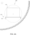
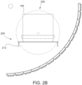
- FIGS. 2A-2C are diagrams illustrating an object 140 conveyed through a field of view (FOV) 200 of imaging assembly 104 (shown in FIG. 1A ).
- FOV 200 defines the area through which object 140 can travel and be imaged by imaging assembly 104.
- FOV 200 is predetermined based on the specific configuration of x-ray source 110 and detector array 112.
- FOV 200 is configured based on the geometry of gantry 102, such that FOV 200 fits within the circumference of gantry 102, as shown in FIG. 1A . If a much larger FOV is desired, typically a larger diameter gantry 102 must be used.
- FIG. 2A illustrates a known conveyor assembly 210 including a conveyor belt 212.
- Object 140 is placed on conveyor belt 212 and transported through FOV 200 of imaging assembly 104.
- Object 140 lies fully within FOV 200 and therefore may be fully imaged.
- conveyor assemblies 210 including "bare" conveyor belts 212 i.e., objects 140 are placed directly on belts 212 have a disadvantage of low efficiency of tracking objects through a full baggage handling system (that includes conveyor assembly 210).
- FIG. 2B illustrates another known conveyor assembly 220 that attempts to overcome the disadvantage of conveyor assembly 210 by placing object 140 within a tray 222 carried on conveyor belt 212. Trays 222 improve the efficiency of object tracking in conveyor assemblies 220. However, as illustrated, placing objects 140 in trays 222 on top of conveyor belts 212 causes a new disadvantage to arise - large objects 140 do not fully fit within FOV 200. In some cases, large objects 140 will not even fit within gantry 102, reducing the maximum size of objects 140 that can be imaged using imaging system 100.
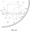
- FIG. 2C illustrates conveyor assembly 106 of imaging system 100.
- conveyor assembly 106 does not include a belt 212 but instead includes a pair of rails 150 coupled to conveyor duct 108. More specifically, conveyor assembly 106 includes a first rail 152 coupled to a first side wall 154 of conveyor duct 108 and a second rail 156 coupled to a second side wall 158 of conveyor duct 108.
- “rail” refers generally to structures suitable to convey (transport) a tray 170 as well as to support or retain trays 170 thereon. Accordingly, each "rail” 152, 156 need not be one singular component but can include a plurality of separate components that cooperate to convey and support trays 170.
- Rails 152, 156 can include continuous rails (e.g., belts) and/or separate rail components (e.g., as illustrated in FIG. 1A ). As illustrated in FIG. 1A , each rail 152, 156 may include a plurality of pulley assemblies. In other embodiments, each rail 152, 156 may include one or more chain belts and sprocket assemblies, or one or more "mini" conveyor belts. In still other embodiments, each rail 152, 156 may include any other suitable conveying structure(s).
- the space between rails 152, 156 is open, with rails 152, 156 defining an open or empty channel 160 such that rails 152, 156 transport trays 170 between rails 152, 156 (as opposed to transporting a tray 222 on top of a belt 212, as shown in FIG. 2B ).
- conveyor assembly 106 enables a base 172 of tray 170 to sit between and below rails 152, 156, such that objects 140 sit lower and can be fully imaged within FOV 200.
- base 172 of tray 170 is positioned within a bottom portion 202 of FOV 200, such that object 140 is lowered with respect to a center 201 of FOV.
- objects 140 may be substantially centered within FOV 200.
- conveyor assembly 106 overcomes the disadvantages of conveyor assembly 210 (object tracking inefficiency) and conveyor assembly 220 (reduced maximum object size and/or incomplete imaging of large objects).
- conveyor assembly 106 enables the imaging of larger objects 140 through a bore 103 defined by gantry 102 compared to conveyor assembly 210, and conveyor assembly 106 ensures complete imaging of objects 140 that would have portions thereof "cut-off" from FOV 200 when using conveyor assembly 220.
- imaging system 100 includes two conveyor ducts 108 and two conveyor assemblies 106 (collectively, "conveyor systems” 165).
- One "front” conveyor assembly 106A transports trays 170 through a first "front” conveyor duct 108A and into gantry 102, and another “rear” conveyor assembly 106B transports trays 170 out of gantry 102 and through a second "rear” conveyor duct 108B.
- conveyor controller 130 controls conveyor assemblies 106 to move at the same, constant speed for optimal imaging of object 140 by imaging assembly 104.
- conveyor ducts 108 are straight, such that conveyor assemblies 106 do not require additional guidance systems to move trays 170 therethrough.
- imaging system 100 may include fewer or more conveyor ducts 108 and conveyor assemblies 106. Additionally or alternatively, imaging system 100 may include otherwise configured conveyor systems 165 (e.g., conveyor systems 165 including much longer conveyor ducts than those illustrated in FIG. 1A ).
- Tray 170 includes base 172 configured to hold an object 140 thereon.
- Base 172 is illustrated as a concave base 172 having a curved, concave surface 174. In other embodiments, base 172 may be a flat base 172 having a substantially planar surface.
- Base 172 includes first and second side edges 176, 178 and first and second end edges 180, 182.
- Tray 170 further includes two opposing side walls 184, 186 and two opposing ends walls 188, 190.
- Each side wall 184, 186 extends from a respective side edge 176, 178 of base 172.
- each end wall 188, 190 extends from a respective end edge 180, 182 of base 172.
- Each side wall 184, 186 extends at an angle ⁇ from base 172.
- Angle ⁇ may measure between about 10° and about 170°, in various embodiments. In the illustrated embodiment, angle ⁇ measures between about 120° and about 150°, or about 135°.
- Each end wall 188, 190 extends at an angle ⁇ from base 180.
- Angle ⁇ may measure between about 0° and about 170°, in various embodiments. In the illustrated embodiment, angle ⁇ measures between about 80° and about 100°, or about 90°.
- a first side wall 184 of side walls 184, 186 includes a first flange 192 extending from first side wall 184 along an edge 194 thereof opposite base 172.
- a second side wall 186 of side walls 184, 186 includes a second flange 196 extending from second side wall 186 along an edge 198 thereof opposite base 172.
- First and second flanges 192, 196 are positioned atop respective rails 152, 156 when tray 170 is placed in conveyor assembly 106. Put another way, first rail 152 receives a bottom surface 193 of first flange 192, and second rail 156 receives a bottom surface 197 of second flange 196. Accordingly, as discussed above, when tray 170 is placed in conveyor assembly 106, base 172 extends between and below rails 152, 156 to position objects 140 lower, with respect to center 201 of FOV 200.
- Exemplary embodiments of methods and systems are described above in detail.
- the methods and systems are not limited to the specific embodiments described herein, but rather, components of systems and/or steps of the methods may be used independently and separately from other components and/or steps described herein. Accordingly, the exemplary embodiment can be implemented and used in connection with many other applications not specifically described herein.
- the above-described tray conveyor systems gantry resting on support wheels may be implemented in any suitable conveyor and/or imaging system.
Landscapes
- Physics & Mathematics (AREA)
- High Energy & Nuclear Physics (AREA)
- Life Sciences & Earth Sciences (AREA)
- General Life Sciences & Earth Sciences (AREA)
- General Physics & Mathematics (AREA)
- Geophysics (AREA)
- Analysing Materials By The Use Of Radiation (AREA)
- Engineering & Computer Science (AREA)
- Mechanical Engineering (AREA)
Claims (8)
- Bildgebungssystem (100), umfassend:einen Förderkanal (108), der eine erste Wand und eine gegenüberliegende zweite Wand umfasst;ein Gerüst (102), das an ein Ende des besagten Förderkanals gekoppelt ist;eine Bildgebungsanordnung (104), die mit dem besagten Gerüst assoziiert ist, wobei die besagte Bildgebungsanordnung umfasst:eine Röntgenstrahlenquelle (110); undeine Vielzahl von Detektoren (114), die ein Sichtfeld, FOV, (200) der besagten Bildgebungsanordnung definieren;eine Förderanordnung (106), die an den besagten Förderkanal gekoppelt ist, wobei die besagte Förderanordnung eine erste Schiene, die an die besagte erste Wand des besagten Förderkanals gekoppelt ist, und eine zweite Schiene, die an die besagte zweite Wand des besagten Förderkanals gekoppelt ist, umfasst, wobei die besagte erste Schiene und die besagte zweite Schiene einen Kanal dazwischen definieren; undeine Wanne (222), die eine Basis umfasst, wobei die besagte Förderanordnung dazu konfiguriert ist, die besagte Wanne in das besagte Gerüst zu transportieren, und wobei sich eine Basis der besagten Wanne zwischen und unter der besagten ersten Schiene und der besagten zweiten Schiene erstreckt, wenn die besagte Förderanordnung die besagte Wanne transportiert; und,wobei die besagte Förderanordnung (106) dazu konfiguriert ist, die besagte Wanne (222) durch das FOV (200) der besagten Bildgebungsanordnung zu transportieren.
- Bildgebungssystem nach Anspruch 1, wobei die besagte Wanne (222) weiterhin eine erste Seitenwand, die sich von einem ersten Rand der besagten Basis erstreckt, eine zweite Seitenwand, die sich von einem gegenüberliegenden zweiten Rand der besagten Basis erstreckt, einen ersten Flansch, der sich von der besagten ersten Seitenwand nach außen erstreckt, und einen zweiten Flansch, der sich von der besagten zweiten Seitenwand nach außen erstreckt, umfasst; und optional wobei sich die besagte erste Seitenwand und die besagte zweite Seitenwand der besagten Wanne von der besagten Basis in einem Winkel zwischen ungefähr 10° und ungefähr 170° erstrecken.
- Bildgebungssystem nach Anspruch 2, wobei die besagte erste Schiene der besagten Förderanordnung den besagten ersten Flansch der besagten Wanne aufnimmt und die besagte zweite Schiene den besagten zweiten Flansch der besagten Wanne aufnimmt; und optional wobei der besagte erste Flansch auf der besagten ersten Schiene aufliegt und der besagte zweite Flansch auf der besagten zweiten Schiene aufliegt.
- Bildgebungssystem nach Anspruch 1, wobei die besagte erste Schiene und die besagte zweite Schiene jeweils mindestens ein Band und mindestens eine Umlenkrolle umfassen.
- Bildgebungssystem nach Anspruch 1, wobei die besagte erste Schiene und die besagte zweite Schiene jeweils mindestens ein Kettenband und mindestens ein Kettenzahnrad umfassen.
- Bildgebungssystem (100) nach Anspruch 1, wobei die besagte Förderanordnung (106) dazu konfiguriert ist, die besagte Wanne (222) durch die besagte Bildgebungsanordnung (104) zu transportieren, so dass die besagte Basis der besagten Wanne in einem unteren Abschnitt des FOV (200) der besagten Bildgebungsanordnung positioniert ist.
- Bildgebungssystem (100) nach Anspruch 1, wobei das besagte Gerüst (102) eine Bohrung definiert und wobei die besagte Wanne dazu konfiguriert ist, ein Objekt mit einer vorbestimmten Größe, die mit der Bohrung durch das FOV (200) der besagten Bildgebungsanordnung (104) assoziiert ist, zu enthalten.
- Verfahren zum Betreiben des Bildgebungssystems nach einem der vorhergehenden Ansprüche, wobei das besagte Verfahren umfasst:Anordnen eines Objekts innerhalb der Wanne (222), wobei das besagte Anordnen eine Basis der Wanne zwischen und unter der ersten Schiene und der zweiten Schiene positioniert;Aktivieren der Förderanordnung (106), um die Wanne (222) in das Gerüst (102) durch das FOV (200) der Bildgebungsanordnung zu transportieren; undBildgeben des Objekts innerhalb der Wanne unter Verwendung der Bildgebungsanordnung (104).
Applications Claiming Priority (2)
| Application Number | Priority Date | Filing Date | Title |
|---|---|---|---|
| US15/436,904 US10444400B2 (en) | 2017-02-20 | 2017-02-20 | Tray conveyor baggage handling and imaging system |
| PCT/US2018/017902 WO2018152072A1 (en) | 2017-02-20 | 2018-02-13 | Tray conveyor baggage handling and imaging system |
Publications (3)
| Publication Number | Publication Date |
|---|---|
| EP3583409A1 EP3583409A1 (de) | 2019-12-25 |
| EP3583409A4 EP3583409A4 (de) | 2020-11-11 |
| EP3583409B1 true EP3583409B1 (de) | 2025-04-23 |
Family
ID=63167124
Family Applications (1)
| Application Number | Title | Priority Date | Filing Date |
|---|---|---|---|
| EP18754757.5A Active EP3583409B1 (de) | 2017-02-20 | 2018-02-13 | Gepäckhandhabungs- und -bildgebungssystem für rinnenförderer |
Country Status (6)
| Country | Link |
|---|---|
| US (1) | US10444400B2 (de) |
| EP (1) | EP3583409B1 (de) |
| CN (1) | CN110337584B (de) |
| AU (1) | AU2018221350B2 (de) |
| CA (1) | CA3053529A1 (de) |
| WO (1) | WO2018152072A1 (de) |
Families Citing this family (4)
| Publication number | Priority date | Publication date | Assignee | Title |
|---|---|---|---|---|
| CN110633614B (zh) * | 2019-06-14 | 2020-06-02 | 安徽瑞羽康农业科技有限公司 | 自适应现场防护机构 |
| CN114114442A (zh) * | 2021-12-29 | 2022-03-01 | 同方威视技术股份有限公司 | 传送装置和检查设备 |
| CN116773557B (zh) * | 2022-12-28 | 2024-02-13 | 清华大学 | 用于ct检测的检测通道及ct检测装置 |
| CN120348624B (zh) * | 2025-06-24 | 2025-09-30 | 晋中兴旺包装科技股份有限公司 | 托盘生产用上料运输装置 |
Citations (1)
| Publication number | Priority date | Publication date | Assignee | Title |
|---|---|---|---|---|
| US20070003009A1 (en) * | 2005-01-10 | 2007-01-04 | Rapiscan Systems | Integrated carry-on baggage cart and passenger screening station |
Family Cites Families (30)
| Publication number | Priority date | Publication date | Assignee | Title |
|---|---|---|---|---|
| US3260349A (en) * | 1965-10-04 | 1966-07-12 | Rapids Standard Co Inc | Coded carrier conveyor system |
| US4199053A (en) * | 1976-12-29 | 1980-04-22 | Casteel Joseph M | Conveyor and tray for luggage |
| GB8725494D0 (en) * | 1987-10-30 | 1987-12-02 | Smith Plastics Ltd H | Container |
| CN2128748Y (zh) * | 1992-08-05 | 1993-03-24 | 李桂友 | 多用定位x线固定滤线栅保护器 |
| EA003073B1 (ru) * | 1999-08-09 | 2002-12-26 | Макс Бегль Бауунтернемунг Гмбх Унд Ко.Кг | Дорога для рельсового транспортного средства, в частности подвесная дорога на магнитной подвеске |
| CN1125332C (zh) * | 1999-11-05 | 2003-10-22 | 清华大学 | 以加速器为辐射源的双车移动式集装箱检测系统 |
| EP1142690A1 (de) * | 2000-04-04 | 2001-10-10 | Brodrene Hartmann A/S | Verfahren und Vorrichtung zum Herstellen von Schalen mit darauf laminierter Kunststoffolie |
| US7062011B1 (en) | 2002-12-10 | 2006-06-13 | Analogic Corporation | Cargo container tomography scanning system |
| CN1842294A (zh) * | 2003-07-01 | 2006-10-04 | 色诺根公司 | 多模式内部成像 |
| DE602004008323T3 (de) * | 2003-10-28 | 2015-04-16 | AEW Delford Systems Ltd., | Aufnahme- und absetzgreifer |
| US20050194540A1 (en) * | 2004-03-08 | 2005-09-08 | Paul Fenster | Methods and apparatus for small footprint imaging system |
| US20100078839A1 (en) | 2005-06-23 | 2010-04-01 | Honeywell International Inc. | Pitch densification of carbon fiber preforms |
| FR2887759B1 (fr) * | 2005-07-04 | 2008-10-17 | Uthemann Cyril De | Procede de tri et de rangement d'instruments tels que des instruments chirurgicaux, et installation pour la mise en oeuvre de ce procede |
| US7384194B2 (en) | 2005-12-09 | 2008-06-10 | Ge Security, Inc. | Apparatus and method for providing a shielding means for an X-ray detection system |
| CN200996943Y (zh) * | 2006-10-09 | 2007-12-26 | 同方威视技术股份有限公司 | 一种货物检查设备 |
| US8138909B2 (en) * | 2007-07-03 | 2012-03-20 | Smiths Detection Inc. | Portable detection system and method |
| CN102539461B (zh) * | 2007-09-06 | 2013-10-09 | 清华大学 | 多瓶检测容器 |
| CN101424648B (zh) * | 2007-10-30 | 2012-10-03 | 清华大学 | 检查系统和检查方法 |
| JP4471011B2 (ja) * | 2008-03-11 | 2010-06-02 | セイコーエプソン株式会社 | 部品試験装置及び部品搬送方法 |
| NL2002441C2 (nl) * | 2009-01-22 | 2010-07-26 | Stork Pmt | Transportsysteem. |
| JP2013505178A (ja) | 2009-09-22 | 2013-02-14 | レイトラム,エル.エル.シー. | ホイール付容器を有するチェックポイントシステム |
| US8462206B1 (en) | 2010-02-25 | 2013-06-11 | Amazon Technologies, Inc. | Image acquisition system |
| US9221640B2 (en) * | 2012-05-02 | 2015-12-29 | Bell And Howell, Llc | Method and system for semi-automated tray loading device |
| CN103674979B (zh) * | 2012-09-19 | 2016-12-21 | 同方威视技术股份有限公司 | 一种行李物品ct安检系统及其探测器装置 |
| EP2711694A1 (de) * | 2012-09-21 | 2014-03-26 | Mettler-Toledo Safeline X-Ray Limited | Verfahren zum Betrieb eines Röntgenprüfsystems mit einer modularen Förderkette |
| CN203224459U (zh) * | 2012-10-30 | 2013-10-02 | 公安部第一研究所 | 一种利用通道式四视角x射线对液态物品进行安全检查的装置 |
| CN104165895B (zh) * | 2014-08-04 | 2016-05-25 | 于双悦 | 工业ct的3d成像系统的成像方法 |
| CN204287075U (zh) * | 2014-12-29 | 2015-04-22 | 同方威视技术股份有限公司 | 一体化安全检查系统 |
| CN104502368B (zh) * | 2014-12-29 | 2018-11-23 | 同方威视技术股份有限公司 | 一体化安全检查系统 |
| CN106185226B (zh) * | 2016-09-29 | 2019-05-03 | 同方威视技术股份有限公司 | 用于集装物检查系统的检测通道的组合输送装置、及集装物检查系统 |
-
2017
- 2017-02-20 US US15/436,904 patent/US10444400B2/en active Active
-
2018
- 2018-02-13 EP EP18754757.5A patent/EP3583409B1/de active Active
- 2018-02-13 WO PCT/US2018/017902 patent/WO2018152072A1/en not_active Ceased
- 2018-02-13 CA CA3053529A patent/CA3053529A1/en active Pending
- 2018-02-13 CN CN201880012126.7A patent/CN110337584B/zh active Active
- 2018-02-13 AU AU2018221350A patent/AU2018221350B2/en active Active
Patent Citations (1)
| Publication number | Priority date | Publication date | Assignee | Title |
|---|---|---|---|---|
| US20070003009A1 (en) * | 2005-01-10 | 2007-01-04 | Rapiscan Systems | Integrated carry-on baggage cart and passenger screening station |
Also Published As
| Publication number | Publication date |
|---|---|
| US10444400B2 (en) | 2019-10-15 |
| EP3583409A1 (de) | 2019-12-25 |
| WO2018152072A1 (en) | 2018-08-23 |
| EP3583409A4 (de) | 2020-11-11 |
| CA3053529A1 (en) | 2018-08-23 |
| CN110337584B (zh) | 2022-11-15 |
| US20180239050A1 (en) | 2018-08-23 |
| CN110337584A (zh) | 2019-10-15 |
| AU2018221350A1 (en) | 2019-08-22 |
| AU2018221350B2 (en) | 2023-02-23 |
Similar Documents
| Publication | Publication Date | Title |
|---|---|---|
| EP3583409B1 (de) | Gepäckhandhabungs- und -bildgebungssystem für rinnenförderer | |
| US7317782B2 (en) | Radiation scanning of cargo conveyances at seaports and the like | |
| US7263160B2 (en) | Method and device for examining an object | |
| US7177391B2 (en) | Imaging inspection apparatus | |
| US7123681B2 (en) | Folded array CT baggage scanner | |
| US7062011B1 (en) | Cargo container tomography scanning system | |
| US7440537B2 (en) | Folded array CT baggage scanner | |
| JPH11508055A (ja) | 複数のステーションを備えたガンマ線吸収型密輸品検出システム | |
| CA2575969A1 (en) | Increased throughput inspection station | |
| JP2009183731A (ja) | X線断層写真合成装置 | |
| JP2022000630A (ja) | 被験者のct検査を実行するctスキャナ及び方法 | |
| CN115598719B (zh) | 检查系统和方法 | |
| JP2000074856A (ja) | X線異物検査装置 | |
| JPH11295243A (ja) | X線ctスキャナ装置 | |
| JP2002228601A (ja) | X線異物検出装置 | |
| CN113514482A (zh) | 静态ct检测设备 | |
| US7352841B2 (en) | Folded array CT baggage scanner | |
| JP3668622B2 (ja) | 物品検査方法及びその装置 | |
| JP7103764B2 (ja) | 荷物検査装置 | |
| JP2021089178A (ja) | X線検査装置 | |
| JP2004333264A (ja) | X線検査装置 | |
| MX2007001435A (en) | Increased throughput inspection station |
Legal Events
| Date | Code | Title | Description |
|---|---|---|---|
| STAA | Information on the status of an ep patent application or granted ep patent |
Free format text: STATUS: THE INTERNATIONAL PUBLICATION HAS BEEN MADE |
|
| PUAI | Public reference made under article 153(3) epc to a published international application that has entered the european phase |
Free format text: ORIGINAL CODE: 0009012 |
|
| STAA | Information on the status of an ep patent application or granted ep patent |
Free format text: STATUS: REQUEST FOR EXAMINATION WAS MADE |
|
| 17P | Request for examination filed |
Effective date: 20190820 |
|
| AK | Designated contracting states |
Kind code of ref document: A1 Designated state(s): AL AT BE BG CH CY CZ DE DK EE ES FI FR GB GR HR HU IE IS IT LI LT LU LV MC MK MT NL NO PL PT RO RS SE SI SK SM TR |
|
| AX | Request for extension of the european patent |
Extension state: BA ME |
|
| DAV | Request for validation of the european patent (deleted) | ||
| DAX | Request for extension of the european patent (deleted) | ||
| A4 | Supplementary search report drawn up and despatched |
Effective date: 20201012 |
|
| RIC1 | Information provided on ipc code assigned before grant |
Ipc: G01N 23/10 20180101AFI20201006BHEP |
|
| RIN1 | Information on inventor provided before grant (corrected) |
Inventor name: GARZON, PEDRO ANDRES |
|
| STAA | Information on the status of an ep patent application or granted ep patent |
Free format text: STATUS: EXAMINATION IS IN PROGRESS |
|
| 17Q | First examination report despatched |
Effective date: 20220719 |
|
| GRAP | Despatch of communication of intention to grant a patent |
Free format text: ORIGINAL CODE: EPIDOSNIGR1 |
|
| STAA | Information on the status of an ep patent application or granted ep patent |
Free format text: STATUS: GRANT OF PATENT IS INTENDED |
|
| INTG | Intention to grant announced |
Effective date: 20240705 |
|
| GRAJ | Information related to disapproval of communication of intention to grant by the applicant or resumption of examination proceedings by the epo deleted |
Free format text: ORIGINAL CODE: EPIDOSDIGR1 |
|
| STAA | Information on the status of an ep patent application or granted ep patent |
Free format text: STATUS: EXAMINATION IS IN PROGRESS |
|
| GRAP | Despatch of communication of intention to grant a patent |
Free format text: ORIGINAL CODE: EPIDOSNIGR1 |
|
| STAA | Information on the status of an ep patent application or granted ep patent |
Free format text: STATUS: GRANT OF PATENT IS INTENDED |
|
| INTC | Intention to grant announced (deleted) | ||
| INTG | Intention to grant announced |
Effective date: 20241114 |
|
| GRAS | Grant fee paid |
Free format text: ORIGINAL CODE: EPIDOSNIGR3 |
|
| GRAA | (expected) grant |
Free format text: ORIGINAL CODE: 0009210 |
|
| STAA | Information on the status of an ep patent application or granted ep patent |
Free format text: STATUS: THE PATENT HAS BEEN GRANTED |
|
| AK | Designated contracting states |
Kind code of ref document: B1 Designated state(s): AL AT BE BG CH CY CZ DE DK EE ES FI FR GB GR HR HU IE IS IT LI LT LU LV MC MK MT NL NO PL PT RO RS SE SI SK SM TR |
|
| RAP3 | Party data changed (applicant data changed or rights of an application transferred) |
Owner name: SMITHS DETECTION INC. |
|
| REG | Reference to a national code |
Ref country code: GB Ref legal event code: FG4D |
|
| RIN1 | Information on inventor provided before grant (corrected) |
Inventor name: GARZON, PEDRO ANDRES |
|
| REG | Reference to a national code |
Ref country code: CH Ref legal event code: EP |
|
| REG | Reference to a national code |
Ref country code: DE Ref legal event code: R096 Ref document number: 602018081319 Country of ref document: DE |
|
| REG | Reference to a national code |
Ref country code: IE Ref legal event code: FG4D |
|
| REG | Reference to a national code |
Ref country code: NL Ref legal event code: MP Effective date: 20250423 |
|
| PG25 | Lapsed in a contracting state [announced via postgrant information from national office to epo] |
Ref country code: NL Free format text: LAPSE BECAUSE OF FAILURE TO SUBMIT A TRANSLATION OF THE DESCRIPTION OR TO PAY THE FEE WITHIN THE PRESCRIBED TIME-LIMIT Effective date: 20250423 |
|
| REG | Reference to a national code |
Ref country code: AT Ref legal event code: MK05 Ref document number: 1788185 Country of ref document: AT Kind code of ref document: T Effective date: 20250423 |
|
| P01 | Opt-out of the competence of the unified patent court (upc) registered |
Free format text: CASE NUMBER: UPC_APP_3855_3583409/2025 Effective date: 20250820 |
|
| PG25 | Lapsed in a contracting state [announced via postgrant information from national office to epo] |
Ref country code: ES Free format text: LAPSE BECAUSE OF FAILURE TO SUBMIT A TRANSLATION OF THE DESCRIPTION OR TO PAY THE FEE WITHIN THE PRESCRIBED TIME-LIMIT Effective date: 20250423 Ref country code: FI Free format text: LAPSE BECAUSE OF FAILURE TO SUBMIT A TRANSLATION OF THE DESCRIPTION OR TO PAY THE FEE WITHIN THE PRESCRIBED TIME-LIMIT Effective date: 20250423 Ref country code: PT Free format text: LAPSE BECAUSE OF FAILURE TO SUBMIT A TRANSLATION OF THE DESCRIPTION OR TO PAY THE FEE WITHIN THE PRESCRIBED TIME-LIMIT Effective date: 20250825 |
|
| REG | Reference to a national code |
Ref country code: LT Ref legal event code: MG9D |
|
| PG25 | Lapsed in a contracting state [announced via postgrant information from national office to epo] |
Ref country code: NO Free format text: LAPSE BECAUSE OF FAILURE TO SUBMIT A TRANSLATION OF THE DESCRIPTION OR TO PAY THE FEE WITHIN THE PRESCRIBED TIME-LIMIT Effective date: 20250723 Ref country code: GR Free format text: LAPSE BECAUSE OF FAILURE TO SUBMIT A TRANSLATION OF THE DESCRIPTION OR TO PAY THE FEE WITHIN THE PRESCRIBED TIME-LIMIT Effective date: 20250724 |
|
| PG25 | Lapsed in a contracting state [announced via postgrant information from national office to epo] |
Ref country code: PL Free format text: LAPSE BECAUSE OF FAILURE TO SUBMIT A TRANSLATION OF THE DESCRIPTION OR TO PAY THE FEE WITHIN THE PRESCRIBED TIME-LIMIT Effective date: 20250423 |
|
| PG25 | Lapsed in a contracting state [announced via postgrant information from national office to epo] |
Ref country code: BG Free format text: LAPSE BECAUSE OF FAILURE TO SUBMIT A TRANSLATION OF THE DESCRIPTION OR TO PAY THE FEE WITHIN THE PRESCRIBED TIME-LIMIT Effective date: 20250423 |
|
| PG25 | Lapsed in a contracting state [announced via postgrant information from national office to epo] |
Ref country code: HR Free format text: LAPSE BECAUSE OF FAILURE TO SUBMIT A TRANSLATION OF THE DESCRIPTION OR TO PAY THE FEE WITHIN THE PRESCRIBED TIME-LIMIT Effective date: 20250423 |
|
| PG25 | Lapsed in a contracting state [announced via postgrant information from national office to epo] |
Ref country code: AT Free format text: LAPSE BECAUSE OF FAILURE TO SUBMIT A TRANSLATION OF THE DESCRIPTION OR TO PAY THE FEE WITHIN THE PRESCRIBED TIME-LIMIT Effective date: 20250423 |
|
| PG25 | Lapsed in a contracting state [announced via postgrant information from national office to epo] |
Ref country code: RS Free format text: LAPSE BECAUSE OF FAILURE TO SUBMIT A TRANSLATION OF THE DESCRIPTION OR TO PAY THE FEE WITHIN THE PRESCRIBED TIME-LIMIT Effective date: 20250723 |
|
| PG25 | Lapsed in a contracting state [announced via postgrant information from national office to epo] |
Ref country code: IS Free format text: LAPSE BECAUSE OF FAILURE TO SUBMIT A TRANSLATION OF THE DESCRIPTION OR TO PAY THE FEE WITHIN THE PRESCRIBED TIME-LIMIT Effective date: 20250823 |
|
| PG25 | Lapsed in a contracting state [announced via postgrant information from national office to epo] |
Ref country code: LV Free format text: LAPSE BECAUSE OF FAILURE TO SUBMIT A TRANSLATION OF THE DESCRIPTION OR TO PAY THE FEE WITHIN THE PRESCRIBED TIME-LIMIT Effective date: 20250423 |
|
| PG25 | Lapsed in a contracting state [announced via postgrant information from national office to epo] |
Ref country code: SM Free format text: LAPSE BECAUSE OF FAILURE TO SUBMIT A TRANSLATION OF THE DESCRIPTION OR TO PAY THE FEE WITHIN THE PRESCRIBED TIME-LIMIT Effective date: 20250423 Ref country code: DK Free format text: LAPSE BECAUSE OF FAILURE TO SUBMIT A TRANSLATION OF THE DESCRIPTION OR TO PAY THE FEE WITHIN THE PRESCRIBED TIME-LIMIT Effective date: 20250423 |
|
| PGFP | Annual fee paid to national office [announced via postgrant information from national office to epo] |
Ref country code: FR Payment date: 20251208 Year of fee payment: 9 |
|
| PG25 | Lapsed in a contracting state [announced via postgrant information from national office to epo] |
Ref country code: CZ Free format text: LAPSE BECAUSE OF FAILURE TO SUBMIT A TRANSLATION OF THE DESCRIPTION OR TO PAY THE FEE WITHIN THE PRESCRIBED TIME-LIMIT Effective date: 20250423 |
|
| PG25 | Lapsed in a contracting state [announced via postgrant information from national office to epo] |
Ref country code: EE Free format text: LAPSE BECAUSE OF FAILURE TO SUBMIT A TRANSLATION OF THE DESCRIPTION OR TO PAY THE FEE WITHIN THE PRESCRIBED TIME-LIMIT Effective date: 20250423 |
|
| PG25 | Lapsed in a contracting state [announced via postgrant information from national office to epo] |
Ref country code: RO Free format text: LAPSE BECAUSE OF FAILURE TO SUBMIT A TRANSLATION OF THE DESCRIPTION OR TO PAY THE FEE WITHIN THE PRESCRIBED TIME-LIMIT Effective date: 20250423 Ref country code: SK Free format text: LAPSE BECAUSE OF FAILURE TO SUBMIT A TRANSLATION OF THE DESCRIPTION OR TO PAY THE FEE WITHIN THE PRESCRIBED TIME-LIMIT Effective date: 20250423 |