EP3583397B1 - Apparatus for detecting and checking defects on a tire at the end of a production process - Google Patents
Apparatus for detecting and checking defects on a tire at the end of a production process Download PDFInfo
- Publication number
- EP3583397B1 EP3583397B1 EP18722715.2A EP18722715A EP3583397B1 EP 3583397 B1 EP3583397 B1 EP 3583397B1 EP 18722715 A EP18722715 A EP 18722715A EP 3583397 B1 EP3583397 B1 EP 3583397B1
- Authority
- EP
- European Patent Office
- Prior art keywords
- tire
- defects
- profilometer
- laser
- laser profilometer
- Prior art date
- Legal status (The legal status is an assumption and is not a legal conclusion. Google has not performed a legal analysis and makes no representation as to the accuracy of the status listed.)
- Active
Links
Images


Classifications
-
- B—PERFORMING OPERATIONS; TRANSPORTING
- B60—VEHICLES IN GENERAL
- B60C—VEHICLE TYRES; TYRE INFLATION; TYRE CHANGING; CONNECTING VALVES TO INFLATABLE ELASTIC BODIES IN GENERAL; DEVICES OR ARRANGEMENTS RELATED TO TYRES
- B60C25/00—Apparatus or tools adapted for mounting, removing or inspecting tyres
- B60C25/002—Inspecting tyres
-
- B—PERFORMING OPERATIONS; TRANSPORTING
- B29—WORKING OF PLASTICS; WORKING OF SUBSTANCES IN A PLASTIC STATE IN GENERAL
- B29D—PRODUCING PARTICULAR ARTICLES FROM PLASTICS OR FROM SUBSTANCES IN A PLASTIC STATE
- B29D30/00—Producing pneumatic or solid tyres or parts thereof
- B29D30/06—Pneumatic tyres or parts thereof (e.g. produced by casting, moulding, compression moulding, injection moulding, centrifugal casting)
- B29D30/0601—Vulcanising tyres; Vulcanising presses for tyres
- B29D30/0633—After-treatment specially adapted for vulcanising tyres
-
- B—PERFORMING OPERATIONS; TRANSPORTING
- B60—VEHICLES IN GENERAL
- B60C—VEHICLE TYRES; TYRE INFLATION; TYRE CHANGING; CONNECTING VALVES TO INFLATABLE ELASTIC BODIES IN GENERAL; DEVICES OR ARRANGEMENTS RELATED TO TYRES
- B60C25/00—Apparatus or tools adapted for mounting, removing or inspecting tyres
- B60C25/002—Inspecting tyres
- B60C25/005—Inspecting tyres inside surface
-
- G—PHYSICS
- G01—MEASURING; TESTING
- G01M—TESTING STATIC OR DYNAMIC BALANCE OF MACHINES OR STRUCTURES; TESTING OF STRUCTURES OR APPARATUS, NOT OTHERWISE PROVIDED FOR
- G01M17/00—Testing of vehicles
- G01M17/007—Wheeled or endless-tracked vehicles
- G01M17/02—Tyres
- G01M17/021—Tyre supporting devices, e.g. chucks
-
- G—PHYSICS
- G01—MEASURING; TESTING
- G01M—TESTING STATIC OR DYNAMIC BALANCE OF MACHINES OR STRUCTURES; TESTING OF STRUCTURES OR APPARATUS, NOT OTHERWISE PROVIDED FOR
- G01M17/00—Testing of vehicles
- G01M17/007—Wheeled or endless-tracked vehicles
- G01M17/02—Tyres
- G01M17/027—Tyres using light, e.g. infrared, ultraviolet or holographic techniques
-
- B—PERFORMING OPERATIONS; TRANSPORTING
- B29—WORKING OF PLASTICS; WORKING OF SUBSTANCES IN A PLASTIC STATE IN GENERAL
- B29D—PRODUCING PARTICULAR ARTICLES FROM PLASTICS OR FROM SUBSTANCES IN A PLASTIC STATE
- B29D30/00—Producing pneumatic or solid tyres or parts thereof
- B29D30/06—Pneumatic tyres or parts thereof (e.g. produced by casting, moulding, compression moulding, injection moulding, centrifugal casting)
- B29D30/0601—Vulcanising tyres; Vulcanising presses for tyres
- B29D30/0633—After-treatment specially adapted for vulcanising tyres
- B29D2030/0634—Measuring, calculating, correcting tyre uniformity, e.g. correcting RFV
-
- B—PERFORMING OPERATIONS; TRANSPORTING
- B29—WORKING OF PLASTICS; WORKING OF SUBSTANCES IN A PLASTIC STATE IN GENERAL
- B29D—PRODUCING PARTICULAR ARTICLES FROM PLASTICS OR FROM SUBSTANCES IN A PLASTIC STATE
- B29D30/00—Producing pneumatic or solid tyres or parts thereof
- B29D30/06—Pneumatic tyres or parts thereof (e.g. produced by casting, moulding, compression moulding, injection moulding, centrifugal casting)
- B29D30/0601—Vulcanising tyres; Vulcanising presses for tyres
- B29D30/0633—After-treatment specially adapted for vulcanising tyres
- B29D2030/0634—Measuring, calculating, correcting tyre uniformity, e.g. correcting RFV
- B29D2030/0635—Measuring and calculating tyre uniformity, e.g. using mathematical methods
Definitions
- the present invention relates to the field of the systems for the automation of the industrial production process of tires.
- the present invention relates to an apparatus and respective process for detecting the possible presence of defects on all surfaces of a tire at the end of the production process.
- Tire, or pneumatics are the elements which are mounted on the wheels and which allow the grip of the vehicle on the road.
- the production process of a tire is based on the following main steps:
- Tire quality control is one of the most sensitive processes and the check for absence of defects on the product, which may have been occurred during the production process before marketing, is essential and must be performed on all manufactured tires; installing a machine which efficiently checks the absence of defects on the manufactured tires, positively improves the quality on tires production line.
- defects means any deviation from a desired condition, independently from whether such a deviation causes a degradation in performance of the tire (which can thus be rejected or declassed) or may be a simple defect (e.g. concerning appearance), which does not cause the rejecting or declassing of the tire. Defects can be:
- This type of "human” visual check has criticalities due to the repeatability of the operation, to the complexity of the parts to be analyzed and to the short and fast times imposed by the industrial production, and further does not provide an objective test of the tire because it is related to the conditions of the operators who are subject to many factors, such as fatigue, stress, physical state and other contingent factors, performing their task.
- the technology progresses such as the tire automation production processes, may make it possible to reduce said criticalities and costs to benefit result objectivity.
- Tire manufacturers are also seeking automated solutions for the defect checking activities which until now have been performed solely by operators who, because of long working shifts, wrongly release to the market many defective products, recurrent false negatives which at the end may damage corporate image reputation and customer retention, discarded products and environmental waste of raw materials and resources, and, ultimately, risks to the safety of drivers on the roads.
- Patents relating to systems and methods for testing tires are known in the prior art; some of the most relevant patents are listed below.
- Patent document EP1148328 illustrates a method consisting in varying the pressure of a tire, causing consequent changes in the shape of the tire and of the structural features/defects; the light projected in particular points on the surface of the tire by means of triangulation is observed and acquired by a camera, the images are sent to a processing system and a model of the tire is processed, the process is repeated and the various models are compared for various tire pressures.
- Patent document WO2013/045594 describes a rapid analysis method of elements in relief on the inner surface of a tire, comprising the steps of: capturing a three-dimensional image of the surface by assigning to each pixel of the image a grayscale value proportional to the topographical elevation of that point, in order to obtain a starting image; transforming the captured image into an orthogonal reference system, in which the abscissa axis represents the circumferential values, and the ordinate axis represents the radial values; assigning to each pixel of the surface a value of height gradient by comparing its elevation with the elevation of a discrete and reduced number of points disposed on a straight line passing through the respective pixel and oriented in the circumferential direction.
- Patent document IT102015000028956 illustrates a "Method and apparatus for detecting defects on the surface of tires" comprising the following steps: preparing the tire; acquiring a digital image, comprising a structure which comprises representative stretches of linear elements of a mesh in a surface portion and representative of possible elongated defects, said stretch of the structure having a respective orientation; providing a model of the mesh in the surface portion, in which each pixel is associated with a first index representing whether the pixel belongs to a mesh portion or not and a second index representative of an orientation at least local of the mesh stretch passing through said pixel; calculating for each pixel of the structure a third index representative of the orientation of the stretch of structure passing through said pixel; and determining, for each pixel of the structure having a corresponding pixel in the mesh pattern belonging to the mesh, if said pixel of the structure belongs to a predetermined defect on the basis of the comparison of the third index and the second index associated with the corresponding pixel in the mesh model.
- Patent document US2016320265 illustrates a method for detecting defects on tires in a tire production process and includes the following steps: providing a tire; acquiring a three-dimensional image of a surface portion of the tire; generating, as a function of the acquired image, a plurality of values which indicate the measure of a profile height of the tire surface portion to be tested; processing, as a function of the plurality of acquired values and according to an interpolation of a plurality of values which indicate an estimation of the tire surface portion to be tested with respect to a reference profile; calculating, as a function of said measured values respect to those of a reference profile, and comparing the values obtained in order to detect possible defects on the tire surface portion.
- the technology underlying said method uses matrix cameras detecting defects only on surface portions of a tire and not on the entire tire; the method does not detect defects by means of techniques based on RGB color detection.
- Patent document WO2016103131 illustrates a method and an apparatus for detecting defects on tires based on a comparison between a reference image of a defect-free portion of the surface of a tire and a sample image of a portion of the surface of the tire to be tested, illuminated by a sidelight source in order to detect possible defects.
- the method according to the said document uses a specific apparatus and is not a complete machine; it tests portions of the surface of the tire and not the entire tire; in order to detect the defects, it uses a technology which is based on the use of sidelight to highlight protrusions or defects of the tire to be tested and to provide a model of it by acquiring two-dimensional images and not provide a three-dimensional model.
- differential expansion (or contraction) of s of a tire sidewall is measured by constructing height profiles of the tire at each of at least two different static pressures to detect defects in the tire; light sources project a plurality of illuminated lines onto a tire and cameras are used to record the position of the lines to construct the height profiles of a rotationally fixed position tire.
- the method is based on the detection of macroscopic defects by inflating the tire at different pressures and consequently examining the variation of the positions of the light lines projected onto the tire and acquired by a camera; it does not perform any detection 3D and cannot examine for small deformations and defects on the surface of the tire to be tested.
- the method is used to detect large structural defects of the tire which are highlighted by inflating the tire at different pressures and plotting the profile of the tire as a function of the position of the projected lines. In all cases, as the tire must be inflated, it must be mounted on a rim and the apparatus is designed to test off-line. Furthermore, said method cannot be applied to the inner sections of the tire.
- the surface of the tire to be analyzed is irradiated with polarized light, the polarized light reflected by the tire surface is detected by a camera which measures its intensity and identifies irregularities; the camera is preferably equipped with a polarizer having at least three or more different directions.
- the aforesaid apparatus employs polarized light and a camera which allows to detect and highlight a tire defect but does not allow its characterization.
- the present patent document by using light as a significant element for detecting defects, does not allow the detection of minor defects as a result of the different reflection due to the different conformation of the tire, to its variable light absorption features as a function of the angle of incidence, of the curvature of the tire and of various sizes that the tire assumes in space at the end of the vulcanization step, when the tire is not inflated and mounted on a rim. Furthermore, said method cannot be applied to the inner sections of the tire.
- US Patent Application published as US 2001/024279 A1 discloses a method and an apparatus for inspecting appearance and shape of a subject body is provided.
- the apparatus allows to inspect defects in a portion of an inner surface of a tire.
- a first picture taking means takes a picture of a linear portion of a subject body lighted by a first slit light to obtain appearance data
- a second picture taking means takes a picture of the same linear portion lighted by a second slit light to obtain shape data
- quality of appearance and shape of the subject body is judged based on the appearance data and the shape data.
- EP 2799848 A1 discloses an appearance inspection apparatus and an appearance inspection method capable of detecting a shape, minute unevenness on the surface, shine or changes in color tone on the surface of a sample under inspection.
- the method includes the steps of acquiring reflected luminance data on the sample surface by casting a slit light having an intermediate wavelength of three types of lights having different wavelengths from each other and receiving reflected light of the slit light, acquiring surface data on the sample surface by casting two lights of different wavelengths other than the intermediate wavelength at a position other than the position illuminated by the slit light on the sample surface from two different directions so as to overlap the two lights with each other and receiving the reflected light, and detecting surface unevenness from a ratio between the intensities of the two lights, changes in color tone by combining the reflected luminance data and the surface data, and gloss on the sample surface based on the presence or absence of surface unevenness and the changes in color tone.
- the main object of the present invention is to overcome most of the drawbacks of the prior art technologies for detecting the defects of a tire by means of a complete quality control apparatus which is fully integrated and autonomous to be inserted as-is at the end of the production process.
- the present invention provides a method according to claim 5 and respective apparatus according to claim 1 for detecting the presence of defects on all the surfaces of a tire at the end of its production process by using advanced digital detection instruments, which provide high-resolution viewing.
- the amount of data collected by said digital detection means is processed by appropriate processing means, which, by means of complex specially developed algorithms, test every surface and portion of the tire, identifying possible defects and providing useful data to define the tires to be rejected or to be repaired and informations upstream of the production process to implement appropriate corrective measures to reduce rejects.
- the invention provides a method and apparatus for three-dimensional viewing and color analysis which automatically detects any defect present on the tire at the end of the production cycle.
- the apparatus uses "laser profilometry” technology to identify and recognize the defects present on the surface of a tire.
- Said products using software algorithms present onboard, enable to perform the three-dimensional analysis of small objects, measure of height, length, width, inclination and volume referred to individual surfaces.
- Said technology by means of reconstructing and the successive processing of a three-dimensional model of the entire tire, allows to detect the presence, automatically recognize and classify all types of structural defects or surface defects with high efficiency and a considerable saving in terms of time and costs. Furthermore, by using RGB color cameras, the apparatus recognizes color defects on the outer surfaces, tread and shoulder, of any tire, regardless of manufacturer and size.
- the apparatus uses five laser-camera assemblies, which enables to test all inner and outer sections of any tire, regardless of manufacturer and sizes of the tire, and three high-resolution RGB camera-illuminator assemblies, which enables to test the outer sections, tread and shoulders.
- the laser-camera assemblies and the RGB camera-illuminator assemblies mounted on automated guides with axes, are automatically positioned in programmed positions, as a function of the size of the tire to be tested in order to scan every millimeter of it.
- the three-dimensional images of all its sections and the color images of the tread and of the outer shoulders are then processed by a defect analysis software, having identified the specific portions which will be processed in case of differences with respect to the model of the tire being tested; if defects are identified, the tire will be scraped or repaired.
- the scans performed simultaneously by the profilometers and by the RGB cameras are obtained by turning at controlled speed the rotating table 17 on which the tire 21 is placed, while the detection, characterization and classification of one or more defects are performed univocally by the software by means of algorithmic matching between the detection zone of the tire sample to test, which is scanned, and the corresponding one of the defect-free reference tire sample.
- the apparatus according to the present invention shown in some layout with a single test station ( figure 1 ) enables to check and detect the defects of the tires by means of laser profilometry technology for the acquiring the individual profiles of the surfaces to test.
- the laser profilometers 1, 2, 3, 4, 5, use triangulation method in order to detect the profile of the surfaces and perform measurements on the surfaces themselves.
- the technique is that of projecting a laser line on the surface to be tested and to continuously acquire, by means of a linear camera positioned at an angle of 25-45° with respect to the laser, the profile drawn by the light and thereby recording the dimensions along the two axes X and Z.
- the laser device performs a relative movement also along the Y axis, whereby continuously acquiring the profiles shown by the camera; said movement is obtained by rotating at controlled speed the table 17 on which the tire is placed.
- a software specifically developed for the application, performs the assembly of the single profiles acquired along the Y axis and thus allows the 3D reconstruction of the scanned surface.
- Each profilometer is provided with linear camera and independent laser, with the technical features required for the section of the tire to be analyzed (acquisition speed of the camera, resolution, optics, filters, laser power, distances between the laser and camera, framed portions, etc.).
- the apparatus requires the use of hi-tech products, selected on the market as a function of the required features and their application and integration in the system.
- the reconstruction of the three-dimensional image of the single surface is obtained starting from the primitive function obtained by means of the cameras in form of software data, or clouds of points in space of the single profiles; said primitive function are integrated in a high-level software which creates the 3D model of the entire scanned surface (tread, shoulder, bead portion).
- a suitably dimensioned laser unit-camera is installed for each of the surfaces which form the tire, inner surface 21.4 and outer surface 21.3 of the tread, inner surface 21.2 and outer surface 21.1 of the shoulder, rim-tire coupling bead portion surface 21.5, for a total of five, each of which provides the 3D image of the surface associated with it.
- All acquired images, obtained by creating a relative movement between tire and laser-camera system, are processed to obtain the 3D model of the complete tire that will be processed by the defect processing software installed on the apparatus.
- the apparatus For analyzing the defects of specific and small size portions of tire, or for small size tires, such as for example tires for motorcycles, which require less stringent technical features than those of standard products available on the market, the apparatus according to the present invention uses, for some sections of the tire, standard profilometers instead of the laser unit-camera, integrating them in the apparatus as smart sensors.
- Each profilometer acquires therefore in sequence the profiles of the section of the rotating tire, constituted by clouds of points in space, with which it is associated (tread, shoulder, etc.).
- the three-dimensional image of the surface of the tire to test, see figure 3 obtained by using the software of the apparatus, starting from the software primitive function of the cameras, contains the X-Y-Z coordinates for each point in the space of the tire itself; for example, the tread shown in fig. 4 containing an abrasion defect, shows the X-Y-Z coordinates of each point in the 3D reconstruction of the same section, see figure 5 .
- a model is created starting from a defect-free reference tire sample: all tire surfaces are scanned to create the model.
- the model creation software requires the presence of the production engineer who, by means of the user-friendly interface with which the apparatus is equipped, interacts with the system to select the portions for defining the parameters of acceptability of the tire in all its portions and for setting the parameters of each defect.
- the creation step of the 3D model it is stored in the database, matching it with the commercial code of the tire.
- the tire is tested by automatic scanning, reconstructing the 3D image and comparing the areas and portions of the tire with the corresponding default 3D model.
- the portions on which are found differences with respect to those of the default model are subjected to a successive analysis for identifying the defect: the processing is performed specifically for each classified portion in which the defect is present, according to parameters set during the model creation step.
- Figures 6 and 7 show two 3D images obtained after scanning the section of the outer shoulder of a tire: the first is the one related to the section of the shoulder of the model of the reference tire sample and the second is the same section of the tire to test, which has a defect in the highlighted portion on the inside of the rim; as can be seen, the two images are identical with the exception of the defect present inside the highlighted circle.
- the apparatus according to the present invention also allows analyzing color defects, which are very important because tire manufacturers use color for different purposes during the production step.
- the cycle described above relates to the single test station apparatus (illustrated in figure 1 ) provided with a single rotating table on which the scanning of the tread, inner and outer surface, of an outer shoulder and, after overturning of the tire, also of the other one, of an inner shoulder and, after overturning of the tire, also of the other one and of the rim-tire coupling bead portion.
- the cycle time required for analyzing a tire according to said process is about 60 seconds.
- the apparatus is equipped with two stations, which are mechanically perfectly identical and each equipped with the profilometers and RGB cameras needed for scanning the assigned surfaces.
- the operation and the defect scanning and analysis software is perfectly equal to the one installed on the single station apparatus, and the stations are duplicated only to allow scanning two tires at the same time, with an evident reduction of the cycle time, enabling to obtain cycle times of about 40 seconds for each tire during a complete test.
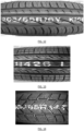
- Figures 8, 9 , 10, 11 show, as an example, some structural and surface defects which may appear on the tires; three images are associated with each defect:
- Figures 12, 13, 14 show, as an example, some defects that may appear on the tread of a tire relative to the barcodes, lettering and commercial reference codes: incorrect positioning of lines ( figure 12 ), distorted letters ( figure 13 ), incorrect lettering positioning ( figure 14 ).
- the apparatus and the method according to the present invention allow the following improvements compared to current technologies:
- the defect detection apparatus according to the present invention is modular and is susceptible to numerous modifications and variants according to manufacturing demands, the operating principle remaining unchanged. In some manufacturing processes, it could be necessary, for example, to vary the number and the position of the detection devices (profilometers and RGB cameras) or in other cases the presence of some of them or not.
- the need may arise that the detection of color defects of the tires is not needed, or the installation of RGB cameras for detecting color defects inside the tire is needed (defects due to contamination of the rubber or escape of steam from the balloon of the vulcanization press).
- profilometers and/or additional axes in the apparatus in order to be able to scan specific parts of the tire.
- the apparatus performs the 3D reconstruction of all surfaces of a tire, also of the surfaces of the shoulders on which reference letters and commercial codes are printed; this is necessary in cases in which said codes are not supplied by the production line before setting the apparatus.
- the apparatus For recognizing said lettering and codes, the apparatus is equipped with specific software, which uses OCR (Optical Character Recognition) algorithms.
- OCR Optical Character Recognition
- the apparatus according to the present invention is also applied to maintenance checks and examinations of the state of tires outside the production process.
Landscapes
- Physics & Mathematics (AREA)
- General Physics & Mathematics (AREA)
- Engineering & Computer Science (AREA)
- Mechanical Engineering (AREA)
- Length Measuring Devices By Optical Means (AREA)
- Investigating Materials By The Use Of Optical Means Adapted For Particular Applications (AREA)
- Tyre Moulding (AREA)
- Tires In General (AREA)
- Length Measuring Devices With Unspecified Measuring Means (AREA)
Description
- The present invention relates to the field of the systems for the automation of the industrial production process of tires.
- More in detail, the present invention relates to an apparatus and respective process for detecting the possible presence of defects on all surfaces of a tire at the end of the production process.
- Tire, or pneumatics, are the elements which are mounted on the wheels and which allow the grip of the vehicle on the road.
- They are one of the most important components of the vehicle because they are crucial for safety: by means of their small footprint, they allow the exchange of all the forces, which make it possible to accelerate, brake and steer the vehicle in all weather conditions.
- The production process of a tire is based on the following main steps:
- compound: the rubber compound of tires consists of 30 types of rubber, filler and other components mixed in gigantic mixers to create a black rubbery compound ready for grinding;
- grinding: the cooled rubber is cut into strips which will form the basic structure of the tire;
- manufacturing: the tire is made proceeding from the inside out; the fabric elements, the steel belts, the beads, the steel wires, the tread and other components are placed in a specific tire manufacturing machine; the result is an unfinished product, known as a "raw tire";
- vulcanization: the raw tire is then vulcanized in molds heated at high temperature, by the vulcanization press, which by means of a balloon outside the tire, compresses all components toward the walls of the mold, conferring the final shape to the tire itself, including the tread pattern and the manufacturer's instruction on the shoulders;
- check: before being considered ready for delivery and sale, each tire is carefully checked by qualified and trained personnel to identify defects, eventually, by means of machines specially designed for detecting even the smallest defects or imperfections.
- Today, all industries in the world which manufacture tires (for cars, motorcycles, trucks, bicycles, etc.) have implemented and installed sophisticated automatic tire production systems, starting from compound preparation, extrusion of the parts which make up the tire, bands, tread, beads, labels, etc., but the check step, i.e. the quality control at end of the production line, it is still performed manually by the operator, who touch and visually checks each tire, both inside and outside, searching defects which can be found visually and by touch.
- Tire quality control is one of the most sensitive processes and the check for absence of defects on the product, which may have been occurred during the production process before marketing, is essential and must be performed on all manufactured tires; installing a machine which efficiently checks the absence of defects on the manufactured tires, positively improves the quality on tires production line.
- The word "defect" means any deviation from a desired condition, independently from whether such a deviation causes a degradation in performance of the tire (which can thus be rejected or declassed) or may be a simple defect (e.g. concerning appearance), which does not cause the rejecting or declassing of the tire. Defects can be:
- of structural type: portions with non-vulcanized compound, alterations of shape, cuts, slipping in the carcass, eccentricity, presence of flat s along the circumference of the tire, thicknesses of parts of the tire, distances exceeding acceptability limits, missing layers and the presence of the open joints during the assembling step, etc.,
- of surface type: presence of foreign bodies on the surface, scratches, scrapes, bubbles, detachments, fissures, bladders, missing elements, foreign bodies, excesses of rubber, lack of rubber, etc.,
- due to color: tire manufacturers use color for various purposes during the manufacturing step, and in particular:
- writing the commercial code of the tire on the tread,
- drawing colored lines for encoding the manufactured tire type; said colored lines are provided on the entire circumference of the tread; this encoding, read by means of color sensors on conveyors, is used to automatically dispatch the tire in the various manufacturing departments,
- highlight the tire brand,
- indicated by variations of the shade of black of the tire, may also highlight contaminations present in the rubber compound and escape of high-pressure air from the balloon inside the mold during the vulcanization step.
- On current tire quality manual control station, the following operations are performed:
- transporting each tire to be tested to the work station,
- tire (inner and outer) manual testing to check deformations, scratches, vesicles, bubbles, etc.,
- tire (inner and outer) visual testing to check structural (or aesthetic) defects detectable by eye.
- This type of "human" visual check has criticalities due to the repeatability of the operation, to the complexity of the parts to be analyzed and to the short and fast times imposed by the industrial production, and further does not provide an objective test of the tire because it is related to the conditions of the operators who are subject to many factors, such as fatigue, stress, physical state and other contingent factors, performing their task.
- The technology progresses, such as the tire automation production processes, may make it possible to reduce said criticalities and costs to benefit result objectivity.
- Tire manufacturers are also seeking automated solutions for the defect checking activities which until now have been performed solely by operators who, because of long working shifts, wrongly release to the market many defective products, recurrent false negatives which at the end may damage corporate image reputation and customer retention, discarded products and environmental waste of raw materials and resources, and, ultimately, risks to the safety of drivers on the roads.
- In other words, the idea underlying the study of these solutions starts from the observation that the visual quality control of industrial products is one of the most repetitive, albeit highly specialized, tasks.
- The insertion of an automatic defect checking station in line, instead of the manual station with operator (three specialized operators on three work shifts), makes it possible to obtain a considerable yearly saving, in addition to obvious advantages of objective results and of guaranteed testing times.
- Automatic stations for performing quality examination tests on some parts of the tires at the end of the production process are known in the prior art and make it possible to detect some defects on the end product, thereby providing a major competitive advantage to tire manufacturers, considering the incidence of the cost of skilled labor and the need for objectivity in each step of the check.
- These are automatic stations mostly made by assembling single components, i.e. 3D cameras and automatisms, which do not provide a complete and fully integrated autonomous quality control system to be inserted as-is in the tire production process.
- Some known systems (Sick, Cognex, Integro Technogies, Testindo) are based on the use of simplified equipments provided with controller for processing the acquired data, and not complete machines (see the apparatus according to the present invention), provided with devices and laser profilometers for testing a tire or its components and respective defects of structural and surface type.
- Patents relating to systems and methods for testing tires are known in the prior art; some of the most relevant patents are listed below.
- Patent document
EP1148328 illustrates a method consisting in varying the pressure of a tire, causing consequent changes in the shape of the tire and of the structural features/defects; the light projected in particular points on the surface of the tire by means of triangulation is observed and acquired by a camera, the images are sent to a processing system and a model of the tire is processed, the process is repeated and the various models are compared for various tire pressures. - Said method however, after inflating the tire at different pressures and acquiring its different shapes at different pressures, detects structural differences of the tire but does not detect its defects; the system may only be used for testing the structural part of the tire out of the production line and requires the tire to be coupled to a rim to be able to inflate it.
- Patent document
WO2013/045594 describes a rapid analysis method of elements in relief on the inner surface of a tire, comprising the steps of: capturing a three-dimensional image of the surface by assigning to each pixel of the image a grayscale value proportional to the topographical elevation of that point, in order to obtain a starting image; transforming the captured image into an orthogonal reference system, in which the abscissa axis represents the circumferential values, and the ordinate axis represents the radial values; assigning to each pixel of the surface a value of height gradient by comparing its elevation with the elevation of a discrete and reduced number of points disposed on a straight line passing through the respective pixel and oriented in the circumferential direction. - Patent document
IT102015000028956 - However, said systems have a drawback due to the fact that in order to obtain a quality control to be used "in-line" in a tire production plant, the control itself must be performed faster and at limited costs; in this context, the computing demand of processing algorithms is crucial, because when it is excessive, the control time is stretched unacceptably and/or the necessary calculation capacity makes the control unfeasible.
- Patent document
US2016320265 illustrates a method for detecting defects on tires in a tire production process and includes the following steps: providing a tire; acquiring a three-dimensional image of a surface portion of the tire; generating, as a function of the acquired image, a plurality of values which indicate the measure of a profile height of the tire surface portion to be tested; processing, as a function of the plurality of acquired values and according to an interpolation of a plurality of values which indicate an estimation of the tire surface portion to be tested with respect to a reference profile; calculating, as a function of said measured values respect to those of a reference profile, and comparing the values obtained in order to detect possible defects on the tire surface portion. - The technology underlying said method uses matrix cameras detecting defects only on surface portions of a tire and not on the entire tire; the method does not detect defects by means of techniques based on RGB color detection.
- Patent document
WO2016103131 illustrates a method and an apparatus for detecting defects on tires based on a comparison between a reference image of a defect-free portion of the surface of a tire and a sample image of a portion of the surface of the tire to be tested, illuminated by a sidelight source in order to detect possible defects. - The method according to the said document uses a specific apparatus and is not a complete machine; it tests portions of the surface of the tire and not the entire tire; in order to detect the defects, it uses a technology which is based on the use of sidelight to highlight protrusions or defects of the tire to be tested and to provide a model of it by acquiring two-dimensional images and not provide a three-dimensional model.
- In patent document
US7805987 , differential expansion (or contraction) of s of a tire sidewall is measured by constructing height profiles of the tire at each of at least two different static pressures to detect defects in the tire; light sources project a plurality of illuminated lines onto a tire and cameras are used to record the position of the lines to construct the height profiles of a rotationally fixed position tire. - The method is based on the detection of macroscopic defects by inflating the tire at different pressures and consequently examining the variation of the positions of the light lines projected onto the tire and acquired by a camera; it does not perform any detection 3D and cannot examine for small deformations and defects on the surface of the tire to be tested. The method is used to detect large structural defects of the tire which are highlighted by inflating the tire at different pressures and plotting the profile of the tire as a function of the position of the projected lines. In all cases, as the tire must be inflated, it must be mounted on a rim and the apparatus is designed to test off-line. Furthermore, said method cannot be applied to the inner sections of the tire.
- In the method shown in patent document
WO2011115256 , the surface of the tire to be analyzed is irradiated with polarized light, the polarized light reflected by the tire surface is detected by a camera which measures its intensity and identifies irregularities; the camera is preferably equipped with a polarizer having at least three or more different directions. - The aforesaid apparatus employs polarized light and a camera which allows to detect and highlight a tire defect but does not allow its characterization. The present patent document, by using light as a significant element for detecting defects, does not allow the detection of minor defects as a result of the different reflection due to the different conformation of the tire, to its variable light absorption features as a function of the angle of incidence, of the curvature of the tire and of various sizes that the tire assumes in space at the end of the vulcanization step, when the tire is not inflated and mounted on a rim. Furthermore, said method cannot be applied to the inner sections of the tire.
- US Patent Application published as
US 2001/024279 A1 discloses a method and an apparatus for inspecting appearance and shape of a subject body is provided. In particular, the apparatus allows to inspect defects in a portion of an inner surface of a tire. A first picture taking means takes a picture of a linear portion of a subject body lighted by a first slit light to obtain appearance data, a second picture taking means takes a picture of the same linear portion lighted by a second slit light to obtain shape data, and quality of appearance and shape of the subject body is judged based on the appearance data and the shape data. European Patent Application published asEP 2799848 A1 discloses an appearance inspection apparatus and an appearance inspection method capable of detecting a shape, minute unevenness on the surface, shine or changes in color tone on the surface of a sample under inspection. The method includes the steps of acquiring reflected luminance data on the sample surface by casting a slit light having an intermediate wavelength of three types of lights having different wavelengths from each other and receiving reflected light of the slit light, acquiring surface data on the sample surface by casting two lights of different wavelengths other than the intermediate wavelength at a position other than the position illuminated by the slit light on the sample surface from two different directions so as to overlap the two lights with each other and receiving the reflected light, and detecting surface unevenness from a ratio between the intensities of the two lights, changes in color tone by combining the reflected luminance data and the surface data, and gloss on the sample surface based on the presence or absence of surface unevenness and the changes in color tone. - The main object of the present invention is to overcome most of the drawbacks of the prior art technologies for detecting the defects of a tire by means of a complete quality control apparatus which is fully integrated and autonomous to be inserted as-is at the end of the production process. For this purpose, the present invention provides a method according to
claim 5 and respective apparatus according toclaim 1 for detecting the presence of defects on all the surfaces of a tire at the end of its production process by using advanced digital detection instruments, which provide high-resolution viewing. - The amount of data collected by said digital detection means is processed by appropriate processing means, which, by means of complex specially developed algorithms, test every surface and portion of the tire, identifying possible defects and providing useful data to define the tires to be rejected or to be repaired and informations upstream of the production process to implement appropriate corrective measures to reduce rejects.
- Further objects and advantages of the method and the relative apparatus according to the present invention are:
- it enables to perform a 3D reconstruction of all tire surfaces;
- it enables to detect 3D defects which modify the tire surfaces (scratches, scrapes, bubbles, detachments, cracks, bladders, missing parts, foreign bodies, excesses of rubber, lack of rubber, etc.), but also structural defects which alter the geometry of the tire (eccentricity, presence of flat portions along the circumference of the tire, thickness of tire parts, distances exceeding acceptability limits, etc.);
- testing and detecting defects is possible on each inner or outer surface of the tire and on any sector thereof (tread, edge, sidewall, shoulder, bead, side);
- it enables to detect the presence of unexpected colors due to incorrect printing of colored characters; the use of color can produce defects due to:
- ∘ the incorrect position of colored lines,
- ∘ the incorrect position of the commercial code,
- ∘ color smudges on the lines and on the commercial code,
- ∘ differences of the color intensity due to the writing step on the tire,
- ∘ differences of color with respect to the tire model,
- ∘ partial highlighting the tire brand lettering;
- it enables to identify variations of the shades of the black color of the tire which indicate defects originating from contamination of the rubber compound, escapes of steam during the vulcanization step or the lack of some layers in the assembly step (the inner steel wires sections of the tire can be seen);
- it can be applied to any type of tire: tires, as a function of the commercial code, have different rim, tread and shoulder sizes;
- it can be integrated into the end of any production line, either new or for retrofitting of production lines already operating in the sector: the apparatus interfaces with the production line using standard protocols (Profibus, Ethernet TCP/IP, Modbus, etc.);
- it enables to test all tires manufactured on site and not in the laboratory;
- it enables the automatic and integrated management of the different types of tire which arrive at end of the production line in a random sequence.
- For said purposes and advantages, the invention provides a method and apparatus for three-dimensional viewing and color analysis which automatically detects any defect present on the tire at the end of the production cycle.
- The apparatus uses "laser profilometry" technology to identify and recognize the defects present on the surface of a tire.
- This innovative technique is applied in various sectors for checking surfaces and there are standard products, 2D and 3D smart sensors, which integrate laser and camera, complete with optics, within the same container.
- Said products, using software algorithms present onboard, enable to perform the three-dimensional analysis of small objects, measure of height, length, width, inclination and volume referred to individual surfaces.
- Said technology (laser profilometry), by means of reconstructing and the successive processing of a three-dimensional model of the entire tire, allows to detect the presence, automatically recognize and classify all types of structural defects or surface defects with high efficiency and a considerable saving in terms of time and costs. Furthermore, by using RGB color cameras, the apparatus recognizes color defects on the outer surfaces, tread and shoulder, of any tire, regardless of manufacturer and size. The apparatus uses five laser-camera assemblies, which enables to test all inner and outer sections of any tire, regardless of manufacturer and sizes of the tire, and three high-resolution RGB camera-illuminator assemblies, which enables to test the outer sections, tread and shoulders.
- The laser-camera assemblies and the RGB camera-illuminator assemblies, mounted on automated guides with axes, are automatically positioned in programmed positions, as a function of the size of the tire to be tested in order to scan every millimeter of it.
- In order to test the defects on the inner and outer surfaces of the tire it must be scanned throughout all its portions.
- The three-dimensional images of all its sections and the color images of the tread and of the outer shoulders are then processed by a defect analysis software, having identified the specific portions which will be processed in case of differences with respect to the model of the tire being tested; if defects are identified, the tire will be scraped or repaired.
- Further features and advantages of the present invention will be apparent in the light of the detailed description of a preferred, but not exclusive, embodiment of a method and apparatus for checking the defects of a tire at the end of the production process, illustrated by way of non-limiting example, with the aid of the accompanying drawings, wherein:
-
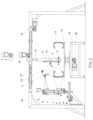
Figure 1 - a layout of the apparatus provided with a single control station; -
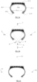
Figure 2- a ) sections both inner and outer which compose the tire and may present defects, b) tire portions with which the various profilometers are associated in order to be able to scan the entire tire, c) tire portions scanned by the RGB color cameras; -
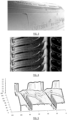
Figure 3 - a 3D reconstruction, after scanning, of the outer shoulder of a tire; -
Figure 4 - a 3D reconstruction, after scanning of the outer surface of the tread of a tire in which an abrasion defect is present; -
Figure 5 - a 3D reconstruction, after scanning, of the tire surface infigure 4 and of the position of the single points which compose it; -
Figure 6 - a 3D reconstruction, after scanning, of the section of the outer shoulder of the reference tire sample; -
Figure 7 - a 3D reconstruction, after scanning, of the section of the outer shoulder corresponding to that inFigure 6 of a sample of tire to be tested which has a defect in the highlighted portion; -
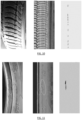
Figures 8, 9 ,10, 11 - some structural and surface defects which may occur on the tires; -
Figures 12, 13, 14 - some color defects which may occur on the tread of the tires, relative to barcodes, lettering and reference commercial codes. - A key of the numeric references used follows for the sake of clarity:
- 1 profilometer for scanning the outer surface of the tread
- 2 profilometer for scanning of the outer surface of a shoulder and, after overturning of the tire, of the other one,
- 3 profilometer for scanning the inner surface of the tread
- 4 profilometer for scanning of the inner surface of a shoulder and, after overturning of the tire, of the other one,
- 5 profilometer for scanning the rim-tire coupling bead portion
- 6 tread profilometer ratio motor on Z axis
- 7 Z axis of tread profilometer
- 8 outer shoulder profilometer ratio motor on Z axis
- 9 Z axis of outer shoulder profilometer
- 10 outer profilometer ratio motors on X axis
- 11 X axis of outer profilometer
- 12 Z axis of inner shoulder profilometer
- 13 Z axis of inner profilometer
- 14 inner profilometer ratio motor on Z axis
- 15 X axis of inner profilometer
- 16 inner profilometer ratio motor on X axis
- 17 rotating table
- 18 rotating table ratio motor
- 19 workbench
- 20 inner profilometer swift on axis X-Z
- 21 tire
- 1. outer surface of the shoulder
- 2. inner surface of the shoulder
- 3. outer surface of the tread
- 4. inner surface of the tread
- 5. tire-rim coupling bead portion
- 22 RGB color camera for detecting the outer surface of the tread
- 23 RGB color camera for detecting the outer surface of the outer side shoulder and, after overturning of the tire, of the other one.
- With reference to said figures is provided in the following the description of some example embodiments of an apparatus for detecting the defects of a
tire 21 at the end of the production process provided with the following main elements: - a
workbench 19, including a rotating table 17, for supporting and moving thetire 21 to test, - profilometer means 1, 2, 3, 4, 5, for scanning the surface of various sections of tire and for detecting the profiles, provided with devices adapted to project a laser line on the surface to be measured and continuously acquire the profile drawn from light by means of linear camera,
- high-resolution RGB color linear camera means 22, 23, for scanning the outer portions of the tire, tread and shoulders, and creating color images,
-
mechanical means - means 6, 8, 10, 14, 16, 18 respectively electromechanical automation means (motors, brushless, sensors) and electronic devices means (PLC, inverter, drive brushless motors and controlled axes) for managing and operating said electromechanical automation means,
- computer mean provided with suitable software for processing the data coming from the profilometers and from the RGB color cameras, creating a 3D model and color model of the tire under test, and managing a database related to all features of the manufactured tires, both those of the automation setting and those of models for analyzing 3D and color defects,
- operator interface, installed aboard the computer, for the interaction between production operator and the apparatus.
- The scans performed simultaneously by the profilometers and by the RGB cameras are obtained by turning at controlled speed the rotating table 17 on which the
tire 21 is placed, while the detection, characterization and classification of one or more defects are performed univocally by the software by means of algorithmic matching between the detection zone of the tire sample to test, which is scanned, and the corresponding one of the defect-free reference tire sample. - The apparatus according to the present invention, shown in some layout with a single test station (
figure 1 ) enables to check and detect the defects of the tires by means of laser profilometry technology for the acquiring the individual profiles of the surfaces to test. - The
laser profilometers - The technique is that of projecting a laser line on the surface to be tested and to continuously acquire, by means of a linear camera positioned at an angle of 25-45° with respect to the laser, the profile drawn by the light and thereby recording the dimensions along the two axes X and Z.
- In order to obtain the 3D image, the laser device performs a relative movement also along the Y axis, whereby continuously acquiring the profiles shown by the camera; said movement is obtained by rotating at controlled speed the table 17 on which the tire is placed.
- A software, specifically developed for the application, performs the assembly of the single profiles acquired along the Y axis and thus allows the 3D reconstruction of the scanned surface.
- Each profilometer is provided with linear camera and independent laser, with the technical features required for the section of the tire to be analyzed (acquisition speed of the camera, resolution, optics, filters, laser power, distances between the laser and camera, framed portions, etc.).
- The apparatus requires the use of hi-tech products, selected on the market as a function of the required features and their application and integration in the system.
- The reconstruction of the three-dimensional image of the single surface is obtained starting from the primitive function obtained by means of the cameras in form of software data, or clouds of points in space of the single profiles; said primitive function are integrated in a high-level software which creates the 3D model of the entire scanned surface (tread, shoulder, bead portion).
- As shown in
figure 2 , a suitably dimensioned laser unit-camera is installed for each of the surfaces which form the tire, inner surface 21.4 and outer surface 21.3 of the tread, inner surface 21.2 and outer surface 21.1 of the shoulder, rim-tire coupling bead portion surface 21.5, for a total of five, each of which provides the 3D image of the surface associated with it. - All acquired images, obtained by creating a relative movement between tire and laser-camera system, are processed to obtain the 3D model of the complete tire that will be processed by the defect processing software installed on the apparatus.
- For analyzing the defects of specific and small size portions of tire, or for small size tires, such as for example tires for motorcycles, which require less stringent technical features than those of standard products available on the market, the apparatus according to the present invention uses, for some sections of the tire, standard profilometers instead of the laser unit-camera, integrating them in the apparatus as smart sensors.
- Each profilometer acquires therefore in sequence the profiles of the section of the rotating tire, constituted by clouds of points in space, with which it is associated (tread, shoulder, etc.).
- These profiles, 8,000-12,000 profiles per tire, are stored by the processing computer.
- The three-dimensional image of the surface of the tire to test, see
figure 3 , obtained by using the software of the apparatus, starting from the software primitive function of the cameras, contains the X-Y-Z coordinates for each point in the space of the tire itself; for example, the tread shown infig. 4 containing an abrasion defect, shows the X-Y-Z coordinates of each point in the 3D reconstruction of the same section, seefigure 5 . - For each commercial code of the tires manufactured in a plant, a model is created starting from a defect-free reference tire sample: all tire surfaces are scanned to create the model.
- During this step, the model creation software requires the presence of the production engineer who, by means of the user-friendly interface with which the apparatus is equipped, interacts with the system to select the portions for defining the parameters of acceptability of the tire in all its portions and for setting the parameters of each defect. At the end of the creation step of the 3D model, it is stored in the database, matching it with the commercial code of the tire.
- During the production step, the tire is tested by automatic scanning, reconstructing the 3D image and comparing the areas and portions of the tire with the corresponding default 3D model.
- The portions on which are found differences with respect to those of the default model are subjected to a successive analysis for identifying the defect: the processing is performed specifically for each classified portion in which the defect is present, according to parameters set during the model creation step.
-
Figures 6 and 7 show two 3D images obtained after scanning the section of the outer shoulder of a tire: the first is the one related to the section of the shoulder of the model of the reference tire sample and the second is the same section of the tire to test, which has a defect in the highlighted portion on the inside of the rim; as can be seen, the two images are identical with the exception of the defect present inside the highlighted circle. - The apparatus according to the present invention also allows analyzing color defects, which are very important because tire manufacturers use color for different purposes during the production step.
- These defects are identified by using high-resolution linear RGB color cameras present in the apparatus, which scan the outer portions of the tire tread and shoulders, and create the color images of the portions. By analyzing the images, as a function of color images previously stored of the same tire model, it is possible to examine the dissimilarities of the tire to test against the reference sample and to determine the defects arising from color differences on the tire surfaces.
- The steps that the apparatus automatically performs during the entire defect examination time are illustrated:
- a. picking the tire to test from the production line and positioning the same on the rotating table of the apparatus; the tire is picked by a robot, or specific machine, which guarantees the centering of tire on the rotating table of the apparatus;
- b. starting the automatic positioning, as a function of the tire type, of the moveable equipment of the profilometers and of the RGB color cameras mounted on controlled axes;
- c. start rotating the rotating table on which the tire is placed to perform a 360° full scan and at the same time to acquire the profiles and color defects along the entire circumference, inside and outside, of the tire (tread outer surface, shoulder outer surface, tread inner surface, other shoulder inner surface, rim-tire coupling bead portion);
- d. processing the acquired profiles, 3D reconstruction of the surfaces and reconstruction of the images acquired by the RGB cameras;
- e. detecting one or more defects, by matching the tire sample to test, already scanned, and a corresponding defect-free reference tire sample (of the same model/type); the defect is detected by means of algorithmic matching between the detection portion of the tire to test and the corresponding one of the reference sample; sophisticated algorithms enables to univocally identify, characterize and classify any defect (type, shape, size, color, etc.);
- f. stopping and repositioning in the starting conditions said profilometer means and said RGB cameras;
- g. automatic overturning of the tire and positioning it on the same rotating table to allow the apparatus to scan the remaining surfaces of the tire, previously not available;
- h. repeating steps b, c, d, e, f;
- i. final picking of the tire at the end of the test operations and repositioning the same on the production line depending on the result of the test defect; the picking of tire is performed by a robot, or a specific machine.
- The cycle described above relates to the single test station apparatus (illustrated in
figure 1 ) provided with a single rotating table on which the scanning of the tread, inner and outer surface, of an outer shoulder and, after overturning of the tire, also of the other one, of an inner shoulder and, after overturning of the tire, also of the other one and of the rim-tire coupling bead portion. - The cycle time required for analyzing a tire according to said process is about 60 seconds.
- When short cycle times defect analysis is required, the apparatus is equipped with two stations, which are mechanically perfectly identical and each equipped with the profilometers and RGB cameras needed for scanning the assigned surfaces.
- The operation and the defect scanning and analysis software is perfectly equal to the one installed on the single station apparatus, and the stations are duplicated only to allow scanning two tires at the same time, with an evident reduction of the cycle time, enabling to obtain cycle times of about 40 seconds for each tire during a complete test.
-
Figures 8, 9 ,10, 11 show, as an example, some structural and surface defects which may appear on the tires; three images are associated with each defect: - photo of the tire: a photo of a tire section with a defect,
- 3D reconstruction: 3D image reconstruction of the tire section where the defect is located,
- processing results: the identified defect with indication of position and size.
-
Figures 12, 13, 14 show, as an example, some defects that may appear on the tread of a tire relative to the barcodes, lettering and commercial reference codes: incorrect positioning of lines (figure 12 ), distorted letters (figure 13 ), incorrect lettering positioning (figure 14 ). - The apparatus and the method according to the present invention allow the following improvements compared to current technologies:
- a full analysis of the inner and outer sections of the tire, by scanning using laser profilometers and RGB cameras (scanning of each part of the tire, even the most hidden);
- the automatic positioning, as a function of the tire type, of moveable equipment of the profilometers and inner and outer RBG cameras;
- matching of dual optical detection technology by means of laser and RGB cameras;
- detecting, 3D modeling and classification of each surface and color defect by matching said technologies.
- Inserting an automatic defect examination station in the production line, replacing the manual station with operator (three specialized operators on three work shifts), also makes it possible:
- to obtain a considerable yearly saving, in addition to the obvious advantages of result objectivity and of guaranteed analysis times,
- to automate the quality examination process of tires at end of the production line which today is particularly expensive and critical, particularly in certain geographical areas in which the operators are not particularly skilled or trained,
- to solve quality problems by reducing the possibility marketing products with defects not detected manually by the operator.
- The cycle time of the method is 40-60 seconds for each tire to test; said time is perfectly comparable to the time currently employed by a qualified operator, but guaranteeing higher efficiency because it is a fully automatic apparatus having much greater result repeatability and guarantee than that of a single operator.
- The defect detection apparatus according to the present invention, shown in some preferred embodiments, is modular and is susceptible to numerous modifications and variants according to manufacturing demands, the operating principle remaining unchanged. In some manufacturing processes, it could be necessary, for example, to vary the number and the position of the detection devices (profilometers and RGB cameras) or in other cases the presence of some of them or not.
- Indeed, the need may arise that the detection of color defects of the tires is not needed, or the installation of RGB cameras for detecting color defects inside the tire is needed (defects due to contamination of the rubber or escape of steam from the balloon of the vulcanization press).
- Another possibility could be given by the need to provide the apparatus with a specific external profilometer for detecting surfaces of special tires which require a more detailed defect analysis, for example for the manufacturing of low-profile tires, in which the size of the shoulder is much lower or other tires with special profiles, also subject to new design.
- For the production of tires of particular manufacturers, it could be necessary to insert profilometers and/or additional axes in the apparatus in order to be able to scan specific parts of the tire.
- The apparatus performs the 3D reconstruction of all surfaces of a tire, also of the surfaces of the shoulders on which reference letters and commercial codes are printed; this is necessary in cases in which said codes are not supplied by the production line before setting the apparatus.
- For recognizing said lettering and codes, the apparatus is equipped with specific software, which uses OCR (Optical Character Recognition) algorithms.
- By means of the apparatus, it is possible to detect any type of defect present on a tire with variable shape, color, size.
- The apparatus according to the present invention is also applied to maintenance checks and examinations of the state of tires outside the production process.
- The object of the invention is susceptible to many changes and variations, all falling within the inventive concept expressed in the attached claims.
- All parts may be replaced with other technically equivalent elements, and the materials may be different according to needs, without departing from the scope of protection of the present invention.
- Although the object was described with particular reference to the attached figures, the reference numbers used in the description and in the claims are used for a better understanding of the invention and do not constitute any limitation to the disclosed scope of protection.
Claims (5)
- Apparatus for detecting and checking defects on a tire at the end of a production process comprising a workstation provided with:- a workbench (19), including a rotating table (17) and automatic overturning means, for supporting a tire (21) and overturning it on the rotating table (17) to test during the same check,- laser profilometer means (1, 2, 3, 4, 5), configured for scanning and detecting a sequence of images referring to the profile of the internal and external surfaces of the tire,- high-resolution RGB color camera means (22, 23), to scan the outer surfaces of the tread and shoulders of the tire to test,- mechanical means (7, 9, 11, 12, 13, 15, 20) supporting and handling said laser profilometer means (1, 2, 3, 4, 5), respectively said color camera means (22, 23),- means (6, 8, 10, 14, 16, 18) respectively for electromechanical automation (motors, brushless, sensors) and electronic devices (PLC, inverter, drive brushless motors and controlled axes) managing and operating said electromechanical automation means,- processor means, implemented with software means, for storing and processing the parameters detected by said laser profilometer means (1, 2, 3, 4, 5), respectively by said color camera means (22, 23), for providing a three dimensional model of the tire to test, as a sample of the relating size and surface characteristics, and for the management of a database including parameters referring to the surface characteristics of respective tire types, organized by category, in condition of absence of surface defects, setting parameters of said electronic and electromechanical automation means, as well as the parameters for checking defects on the same tire surface,- an interface, provided on said processor means, for the interaction between the operator and the apparatus,wherein said laser profilometer means (1, 2, 3, 4, 5), respectively said color camera means (22, 23) are configured to check defects, if present, said tire being able to rotate at a controlled speed on the rotating table (17), and said software means being configured for the subsequent definition and classification, of said surface defects, if detected, by the algorithmic matching between the parameters detected by said laser profilometer means (1, 2, 3, 4, 5), respectively said color camera means (22, 23), referring to the tire to test, and at least one corresponding parameter referring to a tire of the same category, but in condition of absence of surface defects,characterized in that said laser profilometer means (1, 2, 3, 4, 5) and said high-resolution RGB linear color camera means (22, 23) are configured to operate simultaneously,
are configured to be automatically positioned in pre-programmed positions by said electromechanical automation means as a function of the size of the tire to be tested and to perform a full scan of all the profiles of the inner and outer surfaces of the tire to test,and in that
each of said laser profilometer means (1, 2, 3, 4, 5) comprises: a laser device, set for detecting the profile of said tire, and a linear camera on the laser profilometer, oriented at an inclination between 25° and 45° respect to the laser device, and set for the continuous acquisition of the parameters detected by said laser device. - Apparatus according to claim 1, characterized in that said profilometer means comprises five laser profilometer means (1, 2, 3, 4, 5), and said color camera means comprises two high definition color camera means (22, 23).
- Apparatus according to any one of the preceding claims, characterized in that said laser profilometer means comprises, respectively: at least one laser profilometer (1) for scanning the outer surface of the tread, at least one laser profilometer (2) for scanning the outer surface of a shoulder of the tire and the outer surface of the opposite shoulder, at least one laser profilometer (3) for scanning the inner surface of the tread, at least one laser profilometer (4) for scanning the inner surface of a shoulder of the tire and the inner surface of the opposite shoulder, and at least one laser profilometer (5) for scanning the surface of the bead of the tire, and said color camera means comprises at least one color camera (22) for scanning the outer surface of the tread and at least one color camera (23), for scanning the outer surface of a shoulder of the tire and the surface of the opposite shoulder.
- Apparatus according to any one of the preceding claims, characterized in that the linear camera on the laser profilometer and the laser device are set, in each of said laser profilometer (1, 2, 3, 4, 5) referring to each relevant section of the tire to test, on the basis of different predefined parameters such as acquisition speed, resolution, optics and filters referring to the linear camera on the laser profilometer, respectively power, distance from the profilometer linear camera and areas detected referring to the laser device.
- Method to perform checking and detecting of surface defects of a tire at the end of a production process by means of the apparatus according to claim 1, characterized in that it comprises the following steps consisting in:a. removing the tire to test from a production line and positioning the same on a rotating table (17) of a workbench (19);b. operating laser profilometer means (1, 2, 3, 4, 5), respectively a color camera means (22, 23), by mechanical means for supporting and moving said laser profilometer means, respectively said color camera means for setting their position referring to the characteristics of the tire to test, for starting the scanning operation;c. starting the rotation of the rotating table on which the tire is placed to perform a 360° full scan and at the same time to acquire the profiles and color defects along the entire circumference, inside and outside, of the tire;d. processing the parameters detected by said laser profilometer means (1, 2, 3, 4, 5), respectively by said color camera means (22, 23), and providing a three-dimensional model of the tire to test, on the basis of the information detected by said laser profilometer means (1, 2, 3, 4, 5), respectively by the color camera means (22, 23);e. performing the characterization, and classification of the surface defects, if detected, by the algorithmic matching between the parameters detected referring to the tire to test, and at least one corresponding parameter referring to a tire of the same category, but in condition of absence of surface defects;f. stopping and repositioning in the starting conditions said laser profilometer means (1, 2, 3, 4, 5), respectively, the color camera means (22, 23);g. performing the automatic overturning of the tire on this rotating table (17) to allow the scanning of the remaining surfaces of the tire, previously not available;h. repeating steps b, c, d, e, f;i. removing the tire, at the end of check operations and repositioning the same in a corresponding position in the production line depending on the results of the checking and detecting surface defect operations performed.
Applications Claiming Priority (2)
| Application Number | Priority Date | Filing Date | Title |
|---|---|---|---|
| IT102017000016046A IT201700016046A1 (en) | 2017-02-14 | 2017-02-14 | APPARATUS FOR DETECTION AND VERIFICATION OF SURFACE DEFECTS OF A TIRE AT THE END OF A PRODUCTION PROCESS |
| PCT/IB2018/000106 WO2018150256A1 (en) | 2017-02-14 | 2018-02-14 | Apparatus for detecting and checking defects on a tire at the end of a production process |
Publications (3)
| Publication Number | Publication Date |
|---|---|
| EP3583397A1 EP3583397A1 (en) | 2019-12-25 |
| EP3583397C0 EP3583397C0 (en) | 2024-10-23 |
| EP3583397B1 true EP3583397B1 (en) | 2024-10-23 |
Family
ID=59337759
Family Applications (1)
| Application Number | Title | Priority Date | Filing Date |
|---|---|---|---|
| EP18722715.2A Active EP3583397B1 (en) | 2017-02-14 | 2018-02-14 | Apparatus for detecting and checking defects on a tire at the end of a production process |
Country Status (7)
| Country | Link |
|---|---|
| US (1) | US11198339B2 (en) |
| EP (1) | EP3583397B1 (en) |
| JP (1) | JP7248362B2 (en) |
| KR (1) | KR102603141B1 (en) |
| CN (1) | CN110291376A (en) |
| IT (1) | IT201700016046A1 (en) |
| WO (1) | WO2018150256A1 (en) |
Families Citing this family (32)
| Publication number | Priority date | Publication date | Assignee | Title |
|---|---|---|---|---|
| US11472234B2 (en) * | 2016-03-04 | 2022-10-18 | TIREAUDIT.COM, Inc. | Mesh registration system and method for diagnosing tread wear |
| CN111511535B (en) | 2017-12-20 | 2022-08-19 | 普利司通欧洲有限公司 | Method and system for applying sealant to surface of cavity of pneumatic tire |
| US11911982B2 (en) * | 2017-12-20 | 2024-02-27 | Bridgestone Europe Nv/Sa | Method and system for applying a sealing agent to the surface of an internal cavity of a pneumatic tyre |
| IT201800003276A1 (en) * | 2018-03-05 | 2019-09-05 | Bridgestone Europe Nv Sa | APPARATUS FOR ANALYSIS OF THE BEHAVIOR OF A TIRE AT THE INTERFACE WITH THE GROUND |
| DE102018121435A1 (en) * | 2018-09-03 | 2020-03-05 | Bernhard Brain | Device for detecting the condition of old tires |
| JP7462386B2 (en) * | 2019-06-14 | 2024-04-05 | 株式会社シマノ | DETECTION APPARATUS, DETECTION METHOD, GENERATION METHOD, COMPUTER PROGRAM, AND STORAGE MEDIUM |
| EP3990267B1 (en) | 2019-06-27 | 2024-04-17 | Compagnie Generale Des Etablissements Michelin | Assembly for placement of sensors within tire |
| FR3103555B1 (en) * | 2019-11-27 | 2021-12-24 | Michelin & Cie | Tire surface condition assessment system |
| CN115087858B (en) | 2020-02-06 | 2026-01-06 | 斯第莱斯梯克有限公司 | Systems and methods for 360-degree inspection of objects. |
| CN111413277B (en) * | 2020-04-17 | 2023-01-17 | 宁波积微速成智能科技有限公司 | Tire surface defect detection system and method |
| CN111536903B (en) * | 2020-04-29 | 2024-07-02 | 浙江大学 | Device and method for measuring tire morphology by splicing multiple linear laser sensors |
| CN112277535A (en) * | 2020-11-23 | 2021-01-29 | 攀枝花学院 | Tire multi-side tread defect detection device |
| CN112816495A (en) * | 2021-01-06 | 2021-05-18 | 武汉车城物流有限公司 | Automobile tire defect detection system and method |
| KR102589480B1 (en) * | 2021-01-19 | 2023-10-18 | 주식회사 한성시스코 | Automobile tire exterior inspection method using AI deep learning |
| KR102536019B1 (en) * | 2021-01-19 | 2023-05-26 | 주식회사 한성시스코 | Car tire outfit auto test device throughout ai deep learning method using 2d and 3d images |
| CN113188403B (en) * | 2021-05-08 | 2022-04-26 | 赛轮集团股份有限公司 | Tire section measuring workbench |
| CN117178163B (en) * | 2021-05-28 | 2024-08-06 | 横滨橡胶株式会社 | Tire shape measuring device and method |
| CN113916561A (en) * | 2021-12-13 | 2022-01-11 | 东营嘉信机械有限公司 | New energy automobile tire self-checking device |
| CN114324600B (en) * | 2022-03-03 | 2022-06-17 | 季华实验室 | Nondestructive testing method and device for detecting surface aperture defects of wine bottles |
| CN115684177B (en) * | 2022-10-20 | 2024-12-20 | 吉林大学 | Automobile tire defect automatic detection system and method |
| KR102746738B1 (en) | 2022-12-29 | 2025-01-23 | (주)체인브리지 | Tire inspection device and tire inspection process system using the same |
| KR102883069B1 (en) | 2023-01-12 | 2025-11-07 | 주식회사 한성시스코 | Tire reversing device and tire inspection process system using the same |
| NL2034216B1 (en) | 2023-02-23 | 2024-09-05 | Vmi Holland Bv | Method, inspection unit and computer program product for inspecting an inner surface of a tire, and tire processing assembly comprising the inspection unit |
| CN116026280B (en) * | 2023-03-29 | 2023-07-04 | 中策橡胶集团股份有限公司 | Automatic detection equipment and detection method for stress and strain of tire sidewall |
| EP4481361A1 (en) * | 2023-06-23 | 2024-12-25 | Bridgestone Europe NV/SA | Detection of defects from a surface of a buffed tyre casing |
| EP4481678A1 (en) * | 2023-06-23 | 2024-12-25 | Bridgestone Europe NV/SA | Removal of defects from a surface of a buffed tyre casing |
| WO2025024919A1 (en) * | 2023-07-28 | 2025-02-06 | 3Dm Devices Inc. | Apparatus for tire scanning and methods of using same |
| CN117056686B (en) * | 2023-08-14 | 2024-02-02 | 嘉兴市安得特种设备科技有限公司 | Alarming method and system for detecting surface defects of pressure container |
| CN117233171B (en) * | 2023-10-31 | 2024-09-06 | 中国科学院力学研究所 | On-site detection and evaluation method for health of aviation tire |
| CN118031817B (en) * | 2023-12-20 | 2024-08-27 | 钛玛科(北京)工业科技有限公司 | Mechanical device for measuring width of tire vision 3D camera |
| CN118275140B (en) * | 2024-03-06 | 2024-10-22 | 山东奇妙智能科技有限公司 | Tire defect detection device and application method thereof |
| CN120765639A (en) * | 2025-09-02 | 2025-10-10 | 济南大学 | A wheel hub defect detection method and system based on multi-feature vision |
Family Cites Families (23)
| Publication number | Priority date | Publication date | Assignee | Title |
|---|---|---|---|---|
| JP3949796B2 (en) | 1997-11-06 | 2007-07-25 | 株式会社ブリヂストン | Tire shape determination device |
| JP4514007B2 (en) | 1999-12-28 | 2010-07-28 | 株式会社ブリヂストン | Method and apparatus for inspecting appearance of subject |
| DE10019386C2 (en) | 2000-04-19 | 2003-04-03 | Bernward Maehner | Method and device for testing tires |
| US7436504B2 (en) * | 2003-09-10 | 2008-10-14 | Shear Graphics, Llc | Non-destructive testing and imaging |
| DE102007009040C5 (en) | 2007-02-16 | 2013-05-08 | Bernward Mähner | Device and method for testing a tire, in particular by means of an interferometric measuring method |
| FR2925706B1 (en) * | 2007-12-19 | 2010-01-15 | Soc Tech Michelin | DEVICE FOR EVALUATING THE SURFACE OF A TIRE. |
| US7805987B1 (en) | 2008-08-19 | 2010-10-05 | Smith Bradley R | System and method for pneumatic tire defect detection |
| BRPI0917910B1 (en) * | 2008-08-26 | 2019-08-20 | Kabushiki Kaisha Bridgestone | METHOD AND APPARATUS FOR DETECTION OF SURFACE INEQUALITY OF AN OBJECT UNDER INSPECTION |
| CN201555569U (en) | 2009-12-25 | 2010-08-18 | 长安大学 | Tire detection device based on line laser and single camera |
| JP5837283B2 (en) | 2010-03-18 | 2015-12-24 | 株式会社ブリヂストン | Tire appearance inspection method and appearance inspection apparatus |
| JP5620139B2 (en) * | 2010-04-02 | 2014-11-05 | 株式会社ブリヂストン | Tire appearance inspection method and appearance inspection apparatus |
| JP5555049B2 (en) | 2010-05-24 | 2014-07-23 | 株式会社ブリヂストン | Tire inspection device |
| FR2980896B1 (en) | 2011-09-30 | 2016-07-01 | Soc Tech Michelin | METHOD FOR QUICKLY ANALYZING RELIEF ELEMENTS ON THE INTERNAL SURFACE OF A PNEUMATIC |
| JP5882730B2 (en) | 2011-12-28 | 2016-03-09 | 株式会社ブリヂストン | Appearance inspection apparatus and appearance inspection method |
| ITMI20131157A1 (en) | 2013-07-10 | 2015-01-11 | Pirelli | METHOD AND APPARATUS FOR CHECKING TIRES IN A PRODUCTION LINE |
| FR3011079B1 (en) * | 2013-09-26 | 2015-09-25 | Michelin & Cie | INSPECTION METHOD AND PNEUMATIC INSPECTION LINE |
| WO2015097635A1 (en) | 2013-12-23 | 2015-07-02 | Pirelli Tyre S.P.A. | Method and apparatus for detecting defects on tyres in a tyre production process |
| CN114720159B (en) | 2014-12-05 | 2025-08-12 | 倍耐力轮胎股份公司 | Method and apparatus for inspecting tyres |
| RU2640673C1 (en) | 2014-12-22 | 2018-01-11 | Пирелли Тайр С.П.А. | Method and device for detecting defects on tires when manufacturing tires |
| CN108337900B (en) * | 2015-06-30 | 2020-04-07 | 倍耐力轮胎股份公司 | Method and apparatus for detecting defects on the surface of a tyre |
| US10670497B2 (en) * | 2015-12-16 | 2020-06-02 | Pirelli Tyre S.P.A | Device and method for analysis of tyres comprising first and second image acquistion systems |
| RU2733978C2 (en) * | 2015-12-16 | 2020-10-08 | Пирелли Тайр С.П.А. | Method and apparatus for monitoring tires |
| WO2018229805A1 (en) * | 2017-06-12 | 2018-12-20 | Pirelli Tyre S.P.A. | Method for checking tyres |
-
2017
- 2017-02-14 IT IT102017000016046A patent/IT201700016046A1/en unknown
-
2018
- 2018-02-14 CN CN201880011564.1A patent/CN110291376A/en active Pending
- 2018-02-14 EP EP18722715.2A patent/EP3583397B1/en active Active
- 2018-02-14 WO PCT/IB2018/000106 patent/WO2018150256A1/en not_active Ceased
- 2018-02-14 US US16/485,647 patent/US11198339B2/en active Active
- 2018-02-14 JP JP2019542194A patent/JP7248362B2/en active Active
- 2018-02-14 KR KR1020197026783A patent/KR102603141B1/en active Active
Also Published As
| Publication number | Publication date |
|---|---|
| JP2020510814A (en) | 2020-04-09 |
| KR20190118614A (en) | 2019-10-18 |
| WO2018150256A1 (en) | 2018-08-23 |
| US11198339B2 (en) | 2021-12-14 |
| EP3583397C0 (en) | 2024-10-23 |
| JP7248362B2 (en) | 2023-03-29 |
| EP3583397A1 (en) | 2019-12-25 |
| US20200047569A1 (en) | 2020-02-13 |
| IT201700016046A1 (en) | 2018-08-14 |
| KR102603141B1 (en) | 2023-11-15 |
| CN110291376A (en) | 2019-09-27 |
Similar Documents
| Publication | Publication Date | Title |
|---|---|---|
| EP3583397B1 (en) | Apparatus for detecting and checking defects on a tire at the end of a production process | |
| EP3458826B1 (en) | Method and line for checking tyres for vehicle wheels | |
| US8050486B2 (en) | System and method for identifying a feature of a workpiece | |
| US10775273B2 (en) | Method and line for checking tyres for vehicle wheels | |
| EP3317634B1 (en) | Method and apparatus for detecting defects on the surface of tyres | |
| EP2880415B1 (en) | Method for segmenting the surface of a tyre and apparatus operating according to said method | |
| RU2640673C1 (en) | Method and device for detecting defects on tires when manufacturing tires | |
| JP5371848B2 (en) | Tire shape inspection method and tire shape inspection device | |
| US10845271B2 (en) | Method and apparatus for analyzing a surface of a tyre | |
| US9110032B2 (en) | System and methods for inspecting tire wheel assemblies | |
| US9489587B2 (en) | Character reader and container inspection system using character reader | |
| EP3317635B1 (en) | Method and apparatus for detecting defects on the surface of tyres | |
| CN107278261B (en) | Method and apparatus for inspecting tires in a production line | |
| US10899138B2 (en) | Container inspection system controlling printheads to correct for detected ink thickness errors | |
| JP2019505760A (en) | Method and apparatus for inspecting tires | |
| JP7058170B2 (en) | Tire mold side plate inspection method | |
| EP3875893A1 (en) | Method and device for contactless measurement of geometric objects |
Legal Events
| Date | Code | Title | Description |
|---|---|---|---|
| STAA | Information on the status of an ep patent application or granted ep patent |
Free format text: STATUS: UNKNOWN |
|
| STAA | Information on the status of an ep patent application or granted ep patent |
Free format text: STATUS: THE INTERNATIONAL PUBLICATION HAS BEEN MADE |
|
| PUAI | Public reference made under article 153(3) epc to a published international application that has entered the european phase |
Free format text: ORIGINAL CODE: 0009012 |
|
| STAA | Information on the status of an ep patent application or granted ep patent |
Free format text: STATUS: REQUEST FOR EXAMINATION WAS MADE |
|
| 17P | Request for examination filed |
Effective date: 20190912 |
|
| AK | Designated contracting states |
Kind code of ref document: A1 Designated state(s): AL AT BE BG CH CY CZ DE DK EE ES FI FR GB GR HR HU IE IS IT LI LT LU LV MC MK MT NL NO PL PT RO RS SE SI SK SM TR |
|
| AX | Request for extension of the european patent |
Extension state: BA ME |
|
| RIN1 | Information on inventor provided before grant (corrected) |
Inventor name: PAGLIUSO, ANGELO Inventor name: DE STASIO, MICHELE Inventor name: ROMANO, SALVATORE |
|
| DAV | Request for validation of the european patent (deleted) | ||
| DAX | Request for extension of the european patent (deleted) | ||
| STAA | Information on the status of an ep patent application or granted ep patent |
Free format text: STATUS: EXAMINATION IS IN PROGRESS |
|
| 17Q | First examination report despatched |
Effective date: 20220124 |
|
| GRAP | Despatch of communication of intention to grant a patent |
Free format text: ORIGINAL CODE: EPIDOSNIGR1 |
|
| STAA | Information on the status of an ep patent application or granted ep patent |
Free format text: STATUS: GRANT OF PATENT IS INTENDED |
|
| INTG | Intention to grant announced |
Effective date: 20240318 |
|
| RIC1 | Information provided on ipc code assigned before grant |
Ipc: B60C 25/00 20060101ALI20240301BHEP Ipc: B29D 30/06 20060101ALI20240301BHEP Ipc: G01M 17/02 20060101AFI20240301BHEP |
|
| GRAJ | Information related to disapproval of communication of intention to grant by the applicant or resumption of examination proceedings by the epo deleted |
Free format text: ORIGINAL CODE: EPIDOSDIGR1 |
|
| STAA | Information on the status of an ep patent application or granted ep patent |
Free format text: STATUS: EXAMINATION IS IN PROGRESS |
|
| GRAP | Despatch of communication of intention to grant a patent |
Free format text: ORIGINAL CODE: EPIDOSNIGR1 |
|
| STAA | Information on the status of an ep patent application or granted ep patent |
Free format text: STATUS: GRANT OF PATENT IS INTENDED |
|
| INTC | Intention to grant announced (deleted) | ||
| INTG | Intention to grant announced |
Effective date: 20240719 |
|
| GRAS | Grant fee paid |
Free format text: ORIGINAL CODE: EPIDOSNIGR3 |
|
| GRAA | (expected) grant |
Free format text: ORIGINAL CODE: 0009210 |
|
| STAA | Information on the status of an ep patent application or granted ep patent |
Free format text: STATUS: THE PATENT HAS BEEN GRANTED |
|
| AK | Designated contracting states |
Kind code of ref document: B1 Designated state(s): AL AT BE BG CH CY CZ DE DK EE ES FI FR GB GR HR HU IE IS IT LI LT LU LV MC MK MT NL NO PL PT RO RS SE SI SK SM TR |
|
| REG | Reference to a national code |
Ref country code: GB Ref legal event code: FG4D |
|
| REG | Reference to a national code |
Ref country code: CH Ref legal event code: EP |
|
| REG | Reference to a national code |
Ref country code: DE Ref legal event code: R096 Ref document number: 602018075701 Country of ref document: DE |
|
| REG | Reference to a national code |
Ref country code: IE Ref legal event code: FG4D |
|
| U01 | Request for unitary effect filed |
Effective date: 20241104 |
|
| U07 | Unitary effect registered |
Designated state(s): AT BE BG DE DK EE FI FR IT LT LU LV MT NL PT RO SE SI Effective date: 20241113 |
|
| U20 | Renewal fee for the european patent with unitary effect paid |
Year of fee payment: 8 Effective date: 20250225 |
|
| PG25 | Lapsed in a contracting state [announced via postgrant information from national office to epo] |
Ref country code: HR Free format text: LAPSE BECAUSE OF FAILURE TO SUBMIT A TRANSLATION OF THE DESCRIPTION OR TO PAY THE FEE WITHIN THE PRESCRIBED TIME-LIMIT Effective date: 20241023 Ref country code: IS Free format text: LAPSE BECAUSE OF FAILURE TO SUBMIT A TRANSLATION OF THE DESCRIPTION OR TO PAY THE FEE WITHIN THE PRESCRIBED TIME-LIMIT Effective date: 20250223 |
|
| PG25 | Lapsed in a contracting state [announced via postgrant information from national office to epo] |
Ref country code: ES Free format text: LAPSE BECAUSE OF FAILURE TO SUBMIT A TRANSLATION OF THE DESCRIPTION OR TO PAY THE FEE WITHIN THE PRESCRIBED TIME-LIMIT Effective date: 20241023 |
|
| PG25 | Lapsed in a contracting state [announced via postgrant information from national office to epo] |
Ref country code: NO Free format text: LAPSE BECAUSE OF FAILURE TO SUBMIT A TRANSLATION OF THE DESCRIPTION OR TO PAY THE FEE WITHIN THE PRESCRIBED TIME-LIMIT Effective date: 20250123 |
|
| PG25 | Lapsed in a contracting state [announced via postgrant information from national office to epo] |
Ref country code: GR Free format text: LAPSE BECAUSE OF FAILURE TO SUBMIT A TRANSLATION OF THE DESCRIPTION OR TO PAY THE FEE WITHIN THE PRESCRIBED TIME-LIMIT Effective date: 20250124 |
|
| PG25 | Lapsed in a contracting state [announced via postgrant information from national office to epo] |
Ref country code: PL Free format text: LAPSE BECAUSE OF FAILURE TO SUBMIT A TRANSLATION OF THE DESCRIPTION OR TO PAY THE FEE WITHIN THE PRESCRIBED TIME-LIMIT Effective date: 20241023 |
|
| PG25 | Lapsed in a contracting state [announced via postgrant information from national office to epo] |
Ref country code: RS Free format text: LAPSE BECAUSE OF FAILURE TO SUBMIT A TRANSLATION OF THE DESCRIPTION OR TO PAY THE FEE WITHIN THE PRESCRIBED TIME-LIMIT Effective date: 20250123 |
|
| PG25 | Lapsed in a contracting state [announced via postgrant information from national office to epo] |
Ref country code: SM Free format text: LAPSE BECAUSE OF FAILURE TO SUBMIT A TRANSLATION OF THE DESCRIPTION OR TO PAY THE FEE WITHIN THE PRESCRIBED TIME-LIMIT Effective date: 20241023 |
|
| PG25 | Lapsed in a contracting state [announced via postgrant information from national office to epo] |
Ref country code: SK Free format text: LAPSE BECAUSE OF FAILURE TO SUBMIT A TRANSLATION OF THE DESCRIPTION OR TO PAY THE FEE WITHIN THE PRESCRIBED TIME-LIMIT Effective date: 20241023 |
|
| PG25 | Lapsed in a contracting state [announced via postgrant information from national office to epo] |
Ref country code: CZ Free format text: LAPSE BECAUSE OF FAILURE TO SUBMIT A TRANSLATION OF THE DESCRIPTION OR TO PAY THE FEE WITHIN THE PRESCRIBED TIME-LIMIT Effective date: 20241023 |
|
| PLBE | No opposition filed within time limit |
Free format text: ORIGINAL CODE: 0009261 |
|
| STAA | Information on the status of an ep patent application or granted ep patent |
Free format text: STATUS: NO OPPOSITION FILED WITHIN TIME LIMIT |
|
| PG25 | Lapsed in a contracting state [announced via postgrant information from national office to epo] |
Ref country code: MC Free format text: LAPSE BECAUSE OF FAILURE TO SUBMIT A TRANSLATION OF THE DESCRIPTION OR TO PAY THE FEE WITHIN THE PRESCRIBED TIME-LIMIT Effective date: 20241023 |
|
| REG | Reference to a national code |
Ref country code: CH Ref legal event code: PL |
|
| 26N | No opposition filed |
Effective date: 20250724 |
|
| PG25 | Lapsed in a contracting state [announced via postgrant information from national office to epo] |
Ref country code: CH Free format text: LAPSE BECAUSE OF NON-PAYMENT OF DUE FEES Effective date: 20250228 |
|
| GBPC | Gb: european patent ceased through non-payment of renewal fee |
Effective date: 20250214 |
|
| PG25 | Lapsed in a contracting state [announced via postgrant information from national office to epo] |
Ref country code: GB Free format text: LAPSE BECAUSE OF NON-PAYMENT OF DUE FEES Effective date: 20250214 |
|
| PG25 | Lapsed in a contracting state [announced via postgrant information from national office to epo] |
Ref country code: IE Free format text: LAPSE BECAUSE OF NON-PAYMENT OF DUE FEES Effective date: 20250214 |
|
| U20 | Renewal fee for the european patent with unitary effect paid |
Year of fee payment: 9 Effective date: 20260209 |