EP3582887B1 - Wirbelbettsystem - Google Patents
Wirbelbettsystem Download PDFInfo
- Publication number
- EP3582887B1 EP3582887B1 EP18714386.2A EP18714386A EP3582887B1 EP 3582887 B1 EP3582887 B1 EP 3582887B1 EP 18714386 A EP18714386 A EP 18714386A EP 3582887 B1 EP3582887 B1 EP 3582887B1
- Authority
- EP
- European Patent Office
- Prior art keywords
- fluidized bed
- particulate
- air
- dust
- clearance space
- Prior art date
- Legal status (The legal status is an assumption and is not a legal conclusion. Google has not performed a legal analysis and makes no representation as to the accuracy of the status listed.)
- Active
Links
Images


Classifications
-
- B—PERFORMING OPERATIONS; TRANSPORTING
- B01—PHYSICAL OR CHEMICAL PROCESSES OR APPARATUS IN GENERAL
- B01J—CHEMICAL OR PHYSICAL PROCESSES, e.g. CATALYSIS OR COLLOID CHEMISTRY; THEIR RELEVANT APPARATUS
- B01J8/00—Chemical or physical processes in general, conducted in the presence of fluids and solid particles; Apparatus for such processes
- B01J8/18—Chemical or physical processes in general, conducted in the presence of fluids and solid particles; Apparatus for such processes with fluidised particles
-
- F—MECHANICAL ENGINEERING; LIGHTING; HEATING; WEAPONS; BLASTING
- F26—DRYING
- F26B—DRYING SOLID MATERIALS OR OBJECTS BY REMOVING LIQUID THEREFROM
- F26B25/00—Details of general application not covered by group F26B21/00 or F26B23/00
- F26B25/005—Treatment of dryer exhaust gases
- F26B25/007—Dust filtering; Exhaust dust filters
-
- B—PERFORMING OPERATIONS; TRANSPORTING
- B01—PHYSICAL OR CHEMICAL PROCESSES OR APPARATUS IN GENERAL
- B01D—SEPARATION
- B01D46/00—Filters or filtering processes specially modified for separating dispersed particles from gases or vapours
- B01D46/0039—Filters or filtering processes specially modified for separating dispersed particles from gases or vapours with flow guiding by feed or discharge devices
- B01D46/0041—Filters or filtering processes specially modified for separating dispersed particles from gases or vapours with flow guiding by feed or discharge devices for feeding
-
- B—PERFORMING OPERATIONS; TRANSPORTING
- B01—PHYSICAL OR CHEMICAL PROCESSES OR APPARATUS IN GENERAL
- B01J—CHEMICAL OR PHYSICAL PROCESSES, e.g. CATALYSIS OR COLLOID CHEMISTRY; THEIR RELEVANT APPARATUS
- B01J2/00—Processes or devices for granulating materials, e.g. fertilisers in general; Rendering particulate materials free flowing in general, e.g. making them hydrophobic
- B01J2/16—Processes or devices for granulating materials, e.g. fertilisers in general; Rendering particulate materials free flowing in general, e.g. making them hydrophobic by suspending the powder material in a gas, e.g. in fluidised beds or as a falling curtain
-
- B—PERFORMING OPERATIONS; TRANSPORTING
- B01—PHYSICAL OR CHEMICAL PROCESSES OR APPARATUS IN GENERAL
- B01J—CHEMICAL OR PHYSICAL PROCESSES, e.g. CATALYSIS OR COLLOID CHEMISTRY; THEIR RELEVANT APPARATUS
- B01J8/00—Chemical or physical processes in general, conducted in the presence of fluids and solid particles; Apparatus for such processes
- B01J8/18—Chemical or physical processes in general, conducted in the presence of fluids and solid particles; Apparatus for such processes with fluidised particles
- B01J8/1818—Feeding of the fluidising gas
-
- F—MECHANICAL ENGINEERING; LIGHTING; HEATING; WEAPONS; BLASTING
- F23—COMBUSTION APPARATUS; COMBUSTION PROCESSES
- F23C—METHODS OR APPARATUS FOR COMBUSTION USING FLUID FUEL OR SOLID FUEL SUSPENDED IN A CARRIER GAS OR AIR
- F23C10/00—Fluidised bed combustion apparatus
- F23C10/02—Fluidised bed combustion apparatus with means specially adapted for achieving or promoting a circulating movement of particles within the bed or for a recirculation of particles entrained from the bed
- F23C10/04—Fluidised bed combustion apparatus with means specially adapted for achieving or promoting a circulating movement of particles within the bed or for a recirculation of particles entrained from the bed the particles being circulated to a section, e.g. a heat-exchange section or a return duct, at least partially shielded from the combustion zone, before being reintroduced into the combustion zone
- F23C10/08—Fluidised bed combustion apparatus with means specially adapted for achieving or promoting a circulating movement of particles within the bed or for a recirculation of particles entrained from the bed the particles being circulated to a section, e.g. a heat-exchange section or a return duct, at least partially shielded from the combustion zone, before being reintroduced into the combustion zone characterised by the arrangement of separation apparatus, e.g. cyclones, for separating particles from the flue gases
- F23C10/10—Fluidised bed combustion apparatus with means specially adapted for achieving or promoting a circulating movement of particles within the bed or for a recirculation of particles entrained from the bed the particles being circulated to a section, e.g. a heat-exchange section or a return duct, at least partially shielded from the combustion zone, before being reintroduced into the combustion zone characterised by the arrangement of separation apparatus, e.g. cyclones, for separating particles from the flue gases the separation apparatus being located outside the combustion chamber
-
- F—MECHANICAL ENGINEERING; LIGHTING; HEATING; WEAPONS; BLASTING
- F23—COMBUSTION APPARATUS; COMBUSTION PROCESSES
- F23C—METHODS OR APPARATUS FOR COMBUSTION USING FLUID FUEL OR SOLID FUEL SUSPENDED IN A CARRIER GAS OR AIR
- F23C10/00—Fluidised bed combustion apparatus
- F23C10/18—Details; Accessories
- F23C10/24—Devices for removal of material from the bed
- F23C10/26—Devices for removal of material from the bed combined with devices for partial reintroduction of material into the bed, e.g. after separation of agglomerated parts
-
- F—MECHANICAL ENGINEERING; LIGHTING; HEATING; WEAPONS; BLASTING
- F26—DRYING
- F26B—DRYING SOLID MATERIALS OR OBJECTS BY REMOVING LIQUID THEREFROM
- F26B23/00—Heating arrangements
- F26B23/02—Heating arrangements using combustion heating
-
- F—MECHANICAL ENGINEERING; LIGHTING; HEATING; WEAPONS; BLASTING
- F26—DRYING
- F26B—DRYING SOLID MATERIALS OR OBJECTS BY REMOVING LIQUID THEREFROM
- F26B3/00—Drying solid materials or objects by processes involving the application of heat
- F26B3/02—Drying solid materials or objects by processes involving the application of heat by convection, i.e. heat being conveyed from a heat source to the materials or objects to be dried by a gas or vapour, e.g. air
- F26B3/06—Drying solid materials or objects by processes involving the application of heat by convection, i.e. heat being conveyed from a heat source to the materials or objects to be dried by a gas or vapour, e.g. air the gas or vapour flowing through the materials or objects to be dried
- F26B3/08—Drying solid materials or objects by processes involving the application of heat by convection, i.e. heat being conveyed from a heat source to the materials or objects to be dried by a gas or vapour, e.g. air the gas or vapour flowing through the materials or objects to be dried so as to loosen them, e.g. to form a fluidised bed
- F26B3/082—Drying solid materials or objects by processes involving the application of heat by convection, i.e. heat being conveyed from a heat source to the materials or objects to be dried by a gas or vapour, e.g. air the gas or vapour flowing through the materials or objects to be dried so as to loosen them, e.g. to form a fluidised bed arrangements of devices for distributing fluidising gas, e.g. grids, nozzles
-
- F—MECHANICAL ENGINEERING; LIGHTING; HEATING; WEAPONS; BLASTING
- F26—DRYING
- F26B—DRYING SOLID MATERIALS OR OBJECTS BY REMOVING LIQUID THEREFROM
- F26B3/00—Drying solid materials or objects by processes involving the application of heat
- F26B3/02—Drying solid materials or objects by processes involving the application of heat by convection, i.e. heat being conveyed from a heat source to the materials or objects to be dried by a gas or vapour, e.g. air
- F26B3/06—Drying solid materials or objects by processes involving the application of heat by convection, i.e. heat being conveyed from a heat source to the materials or objects to be dried by a gas or vapour, e.g. air the gas or vapour flowing through the materials or objects to be dried
- F26B3/08—Drying solid materials or objects by processes involving the application of heat by convection, i.e. heat being conveyed from a heat source to the materials or objects to be dried by a gas or vapour, e.g. air the gas or vapour flowing through the materials or objects to be dried so as to loosen them, e.g. to form a fluidised bed
- F26B3/084—Drying solid materials or objects by processes involving the application of heat by convection, i.e. heat being conveyed from a heat source to the materials or objects to be dried by a gas or vapour, e.g. air the gas or vapour flowing through the materials or objects to be dried so as to loosen them, e.g. to form a fluidised bed with heat exchange taking place in the fluidised bed, e.g. combined direct and indirect heat exchange
-
- B—PERFORMING OPERATIONS; TRANSPORTING
- B01—PHYSICAL OR CHEMICAL PROCESSES OR APPARATUS IN GENERAL
- B01D—SEPARATION
- B01D2279/00—Filters adapted for separating dispersed particles from gases or vapours specially modified for specific uses
- B01D2279/35—Filters adapted for separating dispersed particles from gases or vapours specially modified for specific uses for venting arrangements
-
- B—PERFORMING OPERATIONS; TRANSPORTING
- B01—PHYSICAL OR CHEMICAL PROCESSES OR APPARATUS IN GENERAL
- B01J—CHEMICAL OR PHYSICAL PROCESSES, e.g. CATALYSIS OR COLLOID CHEMISTRY; THEIR RELEVANT APPARATUS
- B01J2208/00—Processes carried out in the presence of solid particles; Reactors therefor
- B01J2208/00796—Details of the reactor or of the particulate material
- B01J2208/00991—Disengagement zone in fluidised-bed reactors
-
- B—PERFORMING OPERATIONS; TRANSPORTING
- B01—PHYSICAL OR CHEMICAL PROCESSES OR APPARATUS IN GENERAL
- B01J—CHEMICAL OR PHYSICAL PROCESSES, e.g. CATALYSIS OR COLLOID CHEMISTRY; THEIR RELEVANT APPARATUS
- B01J8/00—Chemical or physical processes in general, conducted in the presence of fluids and solid particles; Apparatus for such processes
- B01J8/18—Chemical or physical processes in general, conducted in the presence of fluids and solid particles; Apparatus for such processes with fluidised particles
- B01J8/1845—Chemical or physical processes in general, conducted in the presence of fluids and solid particles; Apparatus for such processes with fluidised particles with particles moving upwards while fluidised
- B01J8/1863—Chemical or physical processes in general, conducted in the presence of fluids and solid particles; Apparatus for such processes with fluidised particles with particles moving upwards while fluidised followed by a downward movement outside the reactor and subsequently re-entering it
Definitions
- This disclosure relates to fluidized beds and more particularly to a continuous fluidized bed system.
- Fluidized bed systems operate to contact solid particles with a fluidization medium (gas or liquid).
- a fluidized bed operates on the principal of creating a fluid solid mixture, which due to operating conditions has properties that resemble a fluid.
- characteristics of solid particles introduced into a fluidized bed may be modified by changes in temperature and or exposure to fluidization medium.
- WO2015166358 discloses an apparatus for removing fluids and/or solids from a mixture of particulate materials, having a container, which forms a ring-shaped process chamber with a multiplicity of cells separated from one another by walls, said cells comprising an inlet cell, intermediate cells and an outlet cell, having an introduction device for the introduction of the mixture for treatment into the inlet cell of the process chamber, having a discharge device for the discharge of the treated mixture out of the outlet cell of the process chamber, having a fan device for feeding a first fluidization medium, in particular in the form of superheated steam, into the process chamber from below through an inflow base in order to generate a fluidized bed
- FR3020451 A1 discloses an apparatus for drying wet heterogeneous particles, comprising a so-called drying column, configured to dry said particles with a hot CO2 gas stream, arranged in said drying column and characterized in that said central column is arranged to rotate in said drying column, and comprises means for injecting a second gas stream of hot CO2, according to a trajectory away from said central column so as to impose on said particles and on said main flow a helical trajectory around said central column
- the disclosed continuous fluidized bed system can be employed for heating, drying, coating, granulating, spray drying, cooling, and other processes involving particulate solids.
- the equipment arrangements used to accomplish all these processes are largely similar, with some modifications as described herein.
- the disclosed fluidized bed system includes a prime air mover, a fluidized bed, and dust collection. Heating and drying applications require an additional heat source, often in the form of a gas fired burner and associated combustion chamber. Cooling applications may require additional cooling sources when ambient conditions cannot meet process requirements.
- the fluidized bed applications rely on ducting to connect each piece of process equipment to complete the unit operation.
- the air heater may be comprised of either direct fired or indirect air heaters where fuels are burned in the airstream; or indirect heated systems such as steam to air heat exchangers, electric resistance heating, or indirect fired heaters.
- the system may also include ducting that recirculates a portion of the gas stream back to the inlet of the blower thus recovering a portion of the thermal energy that would be exhausted in a "once through" gas system.
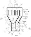
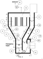
- Figures 1-3 are examples of the fluidized bed system configured as a Cooler, Dryer, and Heater, respectively. Although not illustrated, fluidized beds for use as spray dryers, granulators, and other processes are also possible using the system by modifications of one or more of the examples described in Figures 1-3 .
- particles for which it is desirable to cool, dry, heat, granulate, coat or spray dry are introduced to a fluidized bed 12 to form a group of particles.
- the particles may be uniformly deposited at an entry side of the fluidized bed 12 and are then progressively moved across the fluidized bed to an exit side of the fluidized bed due to the addition of more particles at the entry side. It is desirable to only receive particles at the exit side of the fluidized bed within a predetermined range of sizes, or diameters. Those particles smaller than the desirable size are removed by the system as particulate.
- the system may operate with average particle sizes from 90-100 microns up to about 4 millimeters, and the average particulate sizes removable by the system are in a range of one tenth of the particle size and smaller.
- the term "particle” refers to the desirable material provided at the exit side of the fluidized bed
- the term “particulate” refers to the undesirable material that is removed from the fluidized bed.
- the unit may include an enclosure having an inner chamber (23), a fluidized bed (12), a dust collection system (24), and a fan (11).
- the fluidized bed (12), the dust collection system (24), and the fan (11) may be positioned within the inner chamber (23).
- the length of the unit may vary based on particular system requirements.
- the system is a fully integrated, compact, self-contained package design that provides for efficient installation, operation, and maintenance due to the fully integrated components and minimized duct lengths and losses.
- the system also includes pre-insulated walls (as illustrated by the thick lines in the figures) to minimize heat loss.
- the fluidized bed (12) may include a bed of granules or particles exposed to a stream of gases such that the granules or particles become fluidized.
- the fluidized bed (12) may be configured to process particles and remove particulate.
- gases are recirculated through integral passageways of the system by a variable speed fan, such as a plug style fan (11) as illustrated by arrows.
- the internal passages are ducts that are integral to the modular unit.
- the ducts include: a suction duct (5), a pressure duct (15), a disengaging area (20), a particulate clearance space (4), and a filtered air chamber (9).
- the fan (11) is a centrifugal fan that is speed controlled to maintain a constant and uniform airflow through the fluidized bed (12).
- the system may be modified such that use of an axial flow fan, or a cross flow fan are possible.
- the unit also includes a dust collector system.
- the dust collector system may include, among other things, an integral dust collector (1), a dust hopper (2), an integral conveyor device (3), the particulate clearance space (4), and a filtered air chamber (9).
- the integral dust collector (1) which may be, for example, a bag style filter, a cartridge style filter, a cyclonic separator, or a settling chamber, is mounted directly above the bed in a fluidizing chamber such that the space between the dust hopper (2) and the walls of the fluidizing chamber form the particulate clearance space (4), which serves as an integral conduit through which dust laden gases are directed to the dust collector.
- Particulate from the fluidized bed (12) may be separated from the fluidized bed (12) and transported in the particulate clearance space (4) to the dust hopper (2).
- Particulate separated from the fluidized bed (12) may be received by the dust hopper (2) and removed from the inner chamber (23) by, for example, the integral conveyor device (3), such as a screw conveyor located within the dust hopper (2), for example at the bottom of the dust hopper (2).
- the dimensions of the particulate clearance space (4) may be adjusted to target the separation of specific particulate of a size below a critical threshold in accordance with the desired particle size.
- the dust hopper (2) may be a collection unit configured to collect or capture particulate received from fluidized bed (12) via the particulate clearance space (4).
- the dust hopper (2) may be positioned above the fluidized bed (12).
- the outer wall (26) of the dust hopper (2) may at least partially define the particulate clearance space (4).
- the integral conveyor device (3) may be positioned within the dust hopper (2).
- the dust hopper (2) may be conically shaped to facilitate directing particulate toward the integral conveyor device (3) for conveyance out of the dust hopper (2) and/or the inner chamber (23).
- the dust hopper (2) may be positioned at the disengaging height of the fluidized bed (12).
- the integral conveyor device (3) may be a device positioned within the dust hopper (2) configured to convey particulate from the dust collection system (24).
- a recycle stream may be included.
- the recycle stream may be configured to reintroduce the particulate removed from the dust hopper (2) to the fluidized bed (12).
- the recycle stream may include the integral conveyor device (3) to convey particulate from the dust hopper (2) into the recycle stream.
- the integral conveyor device (3) may be a conveyor screw or conveyor belt, for example.
- the particulate clearance space (4) may be a vertical or angled passageway positioned above the disengaging area (20) configured to channel the particulate separated from the fluidized bed (12) to the dust hopper (2).
- the particulate clearance space (4) may surround the dust collection system (24).
- the particulate clearance space (4) may surround the dust hopper (2).
- the particulate clearance space (4) may be at least partially defined by an outer wall (26) of the dust hopper (2).
- the particulate clear space (4) may be at least partially defined by a wall of the suction duct (5).
- a width of the particulate clearance space (4) may be substantially smaller than a width of the fluidized bed facilitating particulate separated from the fluidized bed (12) to travel into the particulate clearance space (4).
- the gases may be heated either directly by combustion gases provided by a fuel burner (13) or indirectly through heat exchange surface.
- Suction duct (5) shares a common wall with a portion of the dust laden passages of the particulate clearance space (4) so as to create a compact combustion chamber, which minimizes heat loss.
- hot exhaust gases within the suction duct (5) may thermally communicate with the dust hopper and/or advantageously maintain the temperature of the dust hopper (2) at a level to avoid or reduce condensation or any other forms of humidity that could cause caking or fouling in the vicinity of the dust hopper (2).
- Gas heating means such as combustion burners, electric resistance heaters, or heat exchangers may be installed within the passage space formed by the suction duct (5).
- Exhaust gases may be vented to control moisture and combustion products levels from the system by one or more methods that include:
- the system combines a fluidized bed (12) with ductwork, fans, support and access structures, insulation and system wiring into a modular factory manufactured system.
- the packaged all-inclusive unit is not much larger than a traditional dust collector sized for the same process.
- all the ducts are integral flow passages within the housing and minimize lengths and restrictions.
- the plenum geometry of the suction duct (5), a fan housing (28), and the pressure duct (15) between the fan (11) and the fluidized bed (12) accommodates the pressure fan(s) (11) further reducing the space requirements as well as eliminating the need for exterior interconnecting ductwork.
- This design also greatly reduces the externally exposed surface area of the system that is required to be insulated and the shared walls of the integrated flow passages significantly limit the energy transfer area with the environment.
- the suction duct (5) may be a channel configured to direct the air flow to the fan (11), toward the dust collection system (24), or the particulate clearance space (4).
- the suction duct (5) may have a single cross-sectional diameter along a length of the suction duct (5).
- the suction duct (5) may have an expanding or contracting cross-sectional diameter along the length of the suction duct (5), for example to maintain a laminar flow of air within the suction duct (5).
- air or gas in the suction duct (5) may thermally communicate with the dust collection system (24) or a portion of the dust collection system (24).
- This thermal communication may maintain a desired temperature of the dust collection system (24) or portion of the dust collection system (24) and avoid or reduce condensation within the dust collection system (24) or portion of the dust collection system (24).
- the air or gas in the suction duct (5) may thermally communicate with the dust hopper (2), the particulate clearance space (4), the filtered air chamber (9), or the integral conveyor device (3) to maintain a temperature and avoid or reduce condensation therein.
- the design described also, through eliminating duct length and flow restrictions, reduces the overall system pressure drop since there is no external floor mounted fan and custom made duct work to direct air flow into the unit. This reduction in overall pressure drop allows for more flexibility in the selection of deck plate of the fluidized bed (12) and reduces operating costs. Any form of deck plate may be used in the system. This allows the bedplate design to be optimized for the process and for airflow distribution without requiring oversized fans and fan drives.
- the design of the plenum and fan is such that the required bed plate pressure drop required to deliver uniform distribution of gas flow is significantly less than that of other designs. Benefits of this uniform gas distribution as well as the overall geometry of the design is conducive to classification of the solids feed by particle size as well as greatly reducing the disengaging height shown in Figure 4 that is required to minimize particle entrainment.
- the disengaging area (20) includes the disengaging height in the vertical direction.
- the disengaging height is the height of disengaging area (20) above the fluidized bed (12) used to disengage particles from the flow of air in the fluidized bed (12), allowing the particles thus disengaged from the flow of air to fall back into the fluidized bed (12).
- the disengaging height is a threshold height of the disengaging area (20) above the fluidized bed (12) wherein the particulate separates from among the particles and the particulate is carried into the particulate clearance space (4).
- the disengaging height may be in a range from 70% to 200% of the width of the fluidized bed (12).
- the disengaging height may be in a range from 70% to 400% of the width of the fluidized bed. Selection of the disengaging height representing the distance needed between the fluidized bed (12) and the bottom of the dust collector (1) may be chosen to remove particulate of a certain size.
- the disengaging height may be predetermined and preset above the fluidized bed (12) such that the particulate separated from the fluidized bed (12) may travel in a flow of air to reach an entrance to the particulate clearance space (4), the flow of air being through the fluidized bed (12) toward the dust collection system (24).
- the disengaging height may be dynamically adjustable. Adjustment of the disengaging height may be manual or by automatic control. Such adjustment may be performed to lengthen or shorten the duct length above the fluidized bed (12) by, for example, use of a telescoping duct, an accordion style section of the duct, or any other mechanism to change the distance.
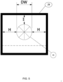
- the performance of the disclosed fluidized bed system may be based on predetermined geometric ratios, such as the geometrical ratios shown in Figures 4 and 5 and listed in Table 1.
- predetermined geometric ratios such as the geometrical ratios shown in Figures 4 and 5 and listed in Table 1.
- Table 1 the percentages for dimensions A, B, C, D, E & F are a percentage of the width of fluidized bed (12).
- the predetermined geometric ratios described in Table 1 have been found to maintain air flow as laminar air flow during operation of the fluidized bed system. The air flow being laminar flow may assist in providing consistent performance of the fluidized bed system and reduce spouting.
- feature A is a diameter of the pressure duct (15)
- feature B is a diameter of a portion of the suction duct (5)
- feature C is a diameter of another portion of the suction duct (5)
- feature D is a diameter of the particulate clearance space (4)
- feature E is a diameter of the filtered air chamber (9).
- “diameter” is not intended to be limited to features having a circular cross-section, but includes any distance across a cross-section of a feature, such as a duct, chamber, or fan.
- H may be 12.5% or greater than the diameter of the wheel (DW) of the fan (11).
- the percentages for the dimension I shown in Figure 5 are a percentage of the wheel diameter, DW, of the fan (11).
- the dimension I may be a distance from an edge of the fan (11) to an edge of the fan housing (28), as shown in Figure 5 .
- Examples of this disclosure can also include the use of adhesives or brazing compounds in the fabrication of the perforated bedplate and its attachment to the support grid and/or air distribution plates.
- Suitable adhesives for this purpose include, but are not limited to epoxies, acrylics, urethanes, thermoplastics, hot melt, and other suitable structural adhesives.
- Suitable brazing compounds for this purpose can include, but are not limited to lead, brass, bronze, solder, silver solder, tin, zinc and mixtures of these metals and alloys. This design further reduces dead areas and potential leaking and spouting points that can be created by the use of traditional mechanical fasteners.
- the fan (11) may direct the air flow from the suction duct (5) to the pressure duct (15).
- An outlet of the suction duct (5) may be coupled to the fan (11) and an inlet of the pressure duct (15) may be coupled to the fan (11).
- the fan (11) may operate to propel the air at a laminar flow to allow controlled and consistent distribution of air flow to the fluidized bed (12).
- the fan (11) is positioned within the fan housing (28) and may be positioned within the inner chamber (23) to eliminate the need for additional ducts and pressure drop calculations.
- the fan (11) may be a variable speed fan.
- the pressure duct (15) may be a channel directing air from the fan (11) to the fluidized bed (12).
- the pressure duct (15) includes a number of features in addition to dimensions A and F to create a desired airflow pattern at the fluidized bed (12).
- the pressure duct (15) may be a generally rectangular passageway.
- the pressure duct (15) may include vanes (25) such as baffles, straighteners, and other features to produce uniform air flow at the fluidized bed (12).
- the vanes (25) may be fixed or moveable. In examples including moveable vanes (25) the vanes (25) may be automated or manually moveable.
- the vanes (25) may direct the flow of air to predetermined portions of the fluidized bed (12).
- air flowing from the fan (11) may change direction by 180 degrees to flow through the fluidized bed (12). Due to the predetermined dimensions and configuration of pressure duct (15), the fluidized bed (12) is not subject to unequal air flow or pressures capable of creating spouting points.
- FIGS 1-4 illustrate a single fan (11) and plenum (suction duct (5) and the pressure duct (15)), however, any number of fans (11) and corresponding plenums may be placed in parallel within the system. Because the pressure plenum design disclosed allows for integral ductless air movers (fans), this easily allows for the use of two or more pressure fans. The integral flow chambers for each of the multiple fans may then be separated with internal baffles allowing for multiple zones down the length of the fluidizing bedplate, each with a separate plug fan (11). Each of these zones of the fluidized bed (12) may now be independently controlled to run at different velocities, pressures, temperatures, etc. Thus, as operational conditions of the fluidized bed (12) changes, zones can be correspondingly controlled.
- the adhesive fabrication detail of the fluidized bed (12) allows for varying of the percent open area or other bedplate specification along the length of the fluidized bed further enhancing the flexibility and adaptability of the system.
- the value of this design can be easily imagined when processing materials that have handling characteristics that change with varying temperature, moisture content, or other process variable. For example, wet particles and particulate that enter the fluidized bed (12) may begin to dry out as the particles and particulate move through the zones, and the corresponding fan speed for subsequent zones may be correspondingly decreased to maintain the desired level of particulate separated from among progressively drying particles.
- the system in combination with the controls disclosed below, also provides for the elimination of condensation near a heater or dryer inlet when processing hygroscopic materials with low surface temperatures. The zone at the inlet can be run at a sufficient temperature such that the air leaving the bed retains enough moisture carrying capacity to prevent condensation on the material surface.
- the dust collection system (24) is located vertically over the fluidized bedplate but is designed to not allow particulate to drop back onto the fluidized bed once separated from the particles.
- This arrangement allows for the disengaging area (20) within the disengaging height above the bedplate to minimize both on-spec material carryover to dust collection as well as off-spec material carryover to product.
- Above the disengaging area (20) the flow path narrows to increase velocity and prevent material that makes it beyond the disengaging height from settling out on the slanted surfaces. This flow path is created by the outer wall of the fluid bed and the walls (26) of the integral dust collection hopper (2).
- the modular design of the unit also allows for varying the area of the clearance space (4). For example, the area of the clearance space (4) may be adjusted by raising and lowering the dust hopper (2) or by using an insert in the clearance space (4) to adjust pressure and velocity of the air flow in the clearance space (4) to further minimize any chance of material carryover.
- This geometry and the ability to generate such uniform airflow distribution at the deck plate of the fluidized bed (12) show how the unit can be employed as an air classifier. Velocity control and distribution are such that not only is spouting in the fluidized bed minimized or eliminated but airflow can be tailored to strip particulate and dusts below a certain size specification with minimal to no carryover of on-size particles. This unique geometry and control also allows the disengaging height to be kept to a minimum, further enhancing the packaged unit's compact attributes. After the dust laden air passes through the clearance space (4), it enters the large volume chamber where the filters (10) and interior of the dust hopper (2) are located.
- the system may include only a portion of the previously discussed dust collection system (24). This may be useful for installations in locations that already have large scale dust collection or wet scrubbing that is external to the system.
- the filters (10), a tube sheet positioned between and at the top of the filters (10) to keep the dirty and filtered air separate, and pulsed air purging of the filters may be omitted, but the dust hopper (2) and integral conveyor device (3) remain.
- the tube sheet and filters (10) may be replaced with baffles designed to impinge the larger and heavier dust and particulate and allow them to fall into the hopper (2). This may greatly reduce the load on the collection or scrubbing system.
- a number of control methodologies are also included in the system. Because of the extremely compact integral flow passages a method of air volume control that does not require a flowmeter such as a hotwire or pitot tube is desired. Instead, in an example, the fan wheel speed, fan static pressure, and fan power load may all be closely monitored. These readings may be used to control the fan speed to target a specific velocity at the fluidized bed plate. This control method can greatly increase heat exchange effectiveness by ensuring that the bed is not severely spouted causing air to pass through the fluidized bedplate without contacting the process material. This same algorithm can be employed to sense bed stagnation caused by a surge in rate or material cohesion. The fan speed can then be dynamically increased (or decreased) to prevent loss of fluidization and material transport. As the stagnation or spouting condition is cleared the monitored variables dynamically return to standard operating conditions to maintain efficient operation. In addition, one or multiple temperatures sensors (17) may be positioned above the fluidized bed (12) to monitor and control the health of the fluidized bed.
- variable open area fresh air inlet dampers (16) and process air outlet dampers (6) in combination with a humidity sensor (18) in the filter section can optimize vent air volumes such that a minimum amount of process air is vented but a certain humidity threshold is never reached. This maximizes heat recovery, minimizes vent air, and further prevents any opportunities for condensation near the inlet for drying and heating applications.
- This humidity control coupled with a "warming mode" during off time, eliminates opportunities for condensation or humidity caking with hygroscopic dusts in the dust hopper (2).
- the warming mode uses heating to keep the internal unit temperature the desired differential above the outside ambient temperature.
- the system may use fan operation with limited venting to hold this temperature, but other heating methods may also be employed.
- an internal bypass damper (22) may be dynamically controlled to introduce heated air from the filtered air chamber (9) to the suction duct (5).
- Some cooling applications may employ supplemental cooling to shrink the overall unit size or to allow for full process rate throughout the year regardless of season.
- the system may use humidification to cool the airstream.
- the humidification cooling can also be used to clean the inlet air stream such as in a low pressure drop horizontal or vertical scrubber.
- Still another advantage of the close compact design is that it allows the use of standardized common components for heating, drying, and cooling systems. Only rearranging of internal baffles, inlet/outlet venting, and size and presence of a burner in the combustion chamber will differ for all three applications.
- the modular design can even allow for quick conversion from once through applications common for dryers and coolers, to partial recirculation applications for economic gas fired heating and temperature sensitive substrate cooling, to full recirculation modes.
- the full recirculation mode can be used to air classify or for heating/cooling applications in which a closed loop is desired or humidity venting is not an issue
- circuitry that includes an instruction processor, such as a Central Processing Unit (CPU), microcontroller, or a microprocessor; or as an Application Specific Integrated Circuit (ASIC), Programmable Logic Device (PLD), or Field Programmable Gate Array (FPGA); or as circuitry that includes discrete logic or other circuit components, including analog circuit components, digital circuit components or both; or any combination thereof.
- instruction processor such as a Central Processing Unit (CPU), microcontroller, or a microprocessor
- ASIC Application Specific Integrated Circuit
- PLD Programmable Logic Device
- FPGA Field Programmable Gate Array
- the circuitry may include discrete interconnected hardware components or may be combined on a single integrated circuit die, distributed among multiple integrated circuit dies, or implemented in a Multiple Chip Module (MCM) of multiple integrated circuit dies in a common package, as examples.
- MCM Multiple Chip Module
- the circuitry may store or access instructions for execution, or may implement its functionality in hardware alone.
- the instructions may be stored in a tangible storage medium that is other than a transitory signal, such as a flash memory, a Random Access Memory (RAM), a Read Only Memory (ROM), an Erasable Programmable Read Only Memory (EPROM); or on a magnetic or optical disc, such as a Compact Disc Read Only Memory (CDROM), Hard Disk Drive (HDD), or other magnetic or optical disk; or in or on another machine-readable medium.
- a product such as a computer program product, may include a storage medium and instructions stored in or on the medium, and the instructions when executed by the circuitry in a device may cause the device to implement any of the processing described above or illustrated in the drawings.
- the circuitry may include multiple distinct system components, such as multiple processors and memories, and may span multiple distributed processing systems.
- Parameters, databases, and other data structures may be separately stored and managed, may be incorporated into a single memory or database, may be logically and physically organized in many different ways, and may be implemented in many different ways.
- Example implementations include linked lists, program variables, hash tables, arrays, records (e.g., database records), objects, and implicit storage mechanisms. Instructions may form parts (e.g., subroutines or other code sections) of a single program, may form multiple separate programs, may be distributed across multiple memories and processors, and may be implemented in many different ways.
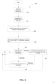
- Fig. 6 shows a flow chart of an example method (500) of separating particulate from the particles and the fluidized bed.
- the method (500) may include receiving (502) particles in the fluidized bed (12) disposed in a housing structure.
- the housing structure may be configured to include the fan (11), the fluidized bed (12), and the dust collection system (24).
- the method (500) may further include subjecting (504) the fluidized bed to the air flow supplied by the fan (11).
- the method may further include separating (506) particulate from the particles included in the fluidized bed (12) within the disengaging height.
- the method may further include (508) receiving the separated particulate in the flow of air at the inlet (27) of the particulate clearance space (4).
- the method may further include channeling the particulate in the flow of air vertically or angled through the particulate clearance space (4) to the dust hopper (2).
- the method may include conveying the particulate from the dust hopper (2) with an integral conveyor device (3) such as a screw conveyor.
- the method may include channeling the particulate through the dust collectors (1), and the dust collectors (1) may be positioned above the dust hopper (2).
- the phrases "at least one of ⁇ A>, ⁇ B>, ... and ⁇ N>” or “at least one of ⁇ A>, ⁇ B>, ... ⁇ N>, or combinations thereof" or " ⁇ A>, ⁇ B>, ... and/or ⁇ N>” are defined by the Applicant in the broadest sense, superseding any other implied definitions hereinbefore or hereinafter unless expressly asserted by the Applicant to the contrary, to mean one or more elements selected from the group comprising A, B, ... and N.
- the phrases mean any combination of one or more of the elements A, B, ... or N including any one element alone or the one element in combination with one or more of the other elements which may also include, in combination, additional elements not listed.
Landscapes
- Engineering & Computer Science (AREA)
- Chemical & Material Sciences (AREA)
- Mechanical Engineering (AREA)
- General Engineering & Computer Science (AREA)
- Life Sciences & Earth Sciences (AREA)
- Combustion & Propulsion (AREA)
- Microbiology (AREA)
- Chemical Kinetics & Catalysis (AREA)
- Organic Chemistry (AREA)
- Sustainable Development (AREA)
- Drying Of Solid Materials (AREA)
- Devices And Processes Conducted In The Presence Of Fluids And Solid Particles (AREA)
- Fluidized-Bed Combustion And Resonant Combustion (AREA)
- Glanulating (AREA)
- Filtering Of Dispersed Particles In Gases (AREA)
Claims (15)
- Wirbelbettsystem, umfassend:ein Gehäuse mit einer inneren Kammer (23);ein Wirbelbett (12), das in der inneren Kammer (23) angeordnet und dazu konfiguriert ist, Partikel zu verarbeiten und Partikel zu entfernen;ein Staubsammelsystem (24), das in der inneren Kammer (23) oberhalb des Wirbelbetts (2) in einer Wirbelkammer in einer Freigabehöhe angeordnet ist,wobei das Staubsammelsystem (24) einen Staubsammler (1), einen Staubtrichter (2), eine integrierte Fördervorrichtung (3) und einen Partikelfreiraum (4) umfasst,wobei der Staubsammler (1) oberhalb eines Staubtrichters (2) positioniert ist, wobei der Staubtrichter (2) auf der Freigabehöhe positioniert und dazu konfiguriert ist, Partikel aufzunehmen, die aus den Partikeln abgeschieden und zum Staubsammler (1) über den Partikelfreiraum (4) transportiert werden, der das Staubsammelsystem (24) in der inneren Kammer (23) zwischen dem Staubtrichter (2) und einer Wand der Wirbelkammer umgibt, undwobei der integrierte Förderer (3), der innerhalb des Staubtrichters (2) positioniert ist, zum Fördern von Partikeln aus dem Staubsammelsystem (24) konfiguriert ist; undein Gebläse (11), das in einem Plenum enthalten ist, wobei das Plenum in der inneren Kammer enthalten ist und einen Saugkanal (5) und einen Druckkanal (15) umfasst, der dazu konfiguriert ist, dem Wirbelbett eine laminare Luftströmung zuzuführen.
- Wirbelbettsystem nach Anspruch 1, wobei der Druckkanal dazu konfiguriert ist, die laminare Luftströmung durch das Wirbelbett in Richtung des Staubsammelsystems und des Partikelfreiraums zu leiten.
- Wirbelbettsystem nach einem der Ansprüche 1 oder 2, wobei der Staubtrichter dazu konfiguriert ist, mindestens einige der Partikel aufzufangen, wobei der Partikelfreiraum eine Außenwand des Staubtrichters umgibt.
- Wirbelbettsystem nach einem der Ansprüche 1 bis 3, wobei der Partikelfreiraum einen nicht-horizontalen Durchgang bildet, der dazu konfiguriert ist, die Partikel von dem Wirbelbett weg und in das Staubsammelsystem zu leiten.
- Wirbelbettsystem nach Anspruch 4, wobei die Freigabehöhe ein vorgegebener Abstand über dem Wirbelbett ist, so dass die aus den Partikeln abgeschiedenen Partikel in einer Luftströmung wandern, um einen Eingang zum Partikelfreiraum zu erreichen, wobei die Luftströmung durch das Wirbelbett in Richtung des Staubsammelsystems verläuft.
- Wirbelbettsystem nach einem der Ansprüche 1 bis 5, des Weiteren umfassend ein Rückführungssystem, das dazu konfiguriert ist, einen Teil der aus den Partikeln abgeschiedenen Partikel in das Wirbelbett zurückzuführen und/oderder integrale Förderer (3) ein Schneckenförderer ist, das Rückführungssystem den Schneckenförderer umfasst, der in dem Staubsammelsystem enthalten ist, wobei der Schneckenförderer dazu konfiguriert ist, die Partikel aus dem Staubsammelsystem zu fördern, und/oderwobei der Druckkanal Schaufeln umfasst, die so angeordnet sind, dass sie die laminare Luftströmung zum Wirbelbett leiten.
- Wirbelbettsystem nach einem der Ansprüche 1 bis 6, wobei der Staubtrichter dazu konfiguriert ist, mindestens einen Teil der Partikel aufzufangen, wobei der Saugkanal und der Staubtrichter in der inneren Kammer so angeordnet sind, dass ein Gas in dem Saugkanal thermisch mit dem Staubtrichter in Verbindung steht.
- Wirbelbettsystem nach einem der Ansprüche 1 bis 7, des Weiteren umfassend:ein Gehäuse; wobeidas Gebläse ein drehzahlveränderliches Gebläse ist, das in dem Gehäuse angeordnet ist;der Saugkanal innerhalb des Gehäuses ausgebildet und mit einem Einlass des drehzahlveränderlichen Gebläses verbunden ist;der Druckkanal im Gehäuse ausgebildet und mit einem Auslass des drehzahlveränderlichen Gebläses verbunden ist;das Wirbelbett in dem Gehäuse enthalten und dazu konfiguriert ist, eine Luftströmung aus dem Druckkanal aufzunehmen; unddas Staubsammelsystem in dem Gehäuse enthalten ist; undder Druckkanal und der Partikelfreiraum sich auf gegenüberliegenden Seiten des Wirbelbetts befinden.
- Wirbelbettsystem nach Anspruch 8, wobei der Partikelfreiraum einen Einlass auf der Freigabehöhe beinhaltet, wobei der Einlass dazu konfiguriert ist, Partikel aufzunehmen, die aus den in das Wirbelbett eingeführten Partikeln abgeschieden sind.
- Wirbelbettsystem nach einem der Ansprüche 8 bis 9, wobei das drehzahlveränderliche Gebläse dazu konfiguriert ist, eine laminare Luftströmung zu erzeugen, und/oderwobei der Druckkanal Schaufeln beinhaltet, die dazu konfiguriert sind, die laminare Luftströmung aufrechtzuerhalten, und/oderwobei die Schaufeln automatisiert sind, um die laminare Luftströmung auf einen vorgegebenen Teil des Wirbelbetts zu richten.
- Wirbelbettsystem nach einem der Ansprüche 8 bis 10, wobei der Druckkanal dazu konfiguriert ist, die Richtung der Luftströmung um 180 Grad vom drehzahlveränderlichen Gebläse zum Wirbelbett zu ändern.
- Wirbelbettsystem nach einem der Ansprüche 8 bis 11, des Weiteren umfassend eine Kammer für gefilterte Luft, die oberhalb des Wirbelbettes angeordnet ist, wobei die Kammer für gefilterte Luft einen Durchmesser von 40 % bis 120 % der Breite des Wirbelbettes aufweist und dazu konfiguriert ist, Partikel aus dem Partikelfreiraum aufzunehmen.
- Wirbelbettsystem nach einem der Ansprüche 8 bis 12, wobei die Luftströmung die laminare Luftströmung ist, die durch einen ersten Teil des Druckkanals mit einem Durchmesser von 10 % bis 110 % der Breite des Wirbelbettes, einen zweiten Teil des Drucckanals mit einem Durchmesser von 50 % bis 130 % der Breite des Wirbelbettes als laminare Strömung aufrechterhalten wird, der Saugkanal einen Durchmesser von 10 % bis 110 % der Breite des Wirbelbettes hat, der Partikelfreiraum einen Durchmesser von 5 % bis 50 % der Breite des Wirbelbettes hat und ein Abstand von einer Kante des drehzahlveränderlichen Gebläses zu einer Kante eines Gebläsegehäuses zwischen 12,50 % und 110 % einer Länge eines Durchmessers des drehzahlveränderlichen Gebläses beträgt.
- Verfahren, umfassend:Aufnehmen von Partikeln in einem Wirbelbett, wobei das Wirbelbett in einer Gehäusestruktur angeordnet ist, wobei die Gehäusestruktur so konfiguriert ist, dass sie ein Gebläse, das Wirbelbett und ein Staubsammelsystem in Fluidverbindung über eine Reihe von Kanälen enthält, wobei die Kanäle einstückig in der Gehäusestruktur ausgebildet sind, wobei das Staubsammelsystem in der Gehäusestruktur über dem Wirbelbett in einer Wirbelkammer auf einer Freigabehöhe angeordnet ist und einen Staubsammler umfasst, der über einem Staubtrichter angeordnet ist, wobei der Staubtrichter in der Freigabehöhe angeordnet ist;Aussetzen des Wirbelbetts einem Luftstrom, der von dem Umwälzgebläse durch die Kanäle zu einer Unterseite des Wirbelbetts geleitet wird;Abscheiden von Partikeln von den im Wirbelbett aufgenommenen Partikeln innerhalb der durch die Kanäle oberhalb des Wirbelbetts gebildeten Freigabehöhe;Aufnehmen der abgeschiedenen Partikel in der Luftströmung an einem Einlass zu einem Partikelfreiraum, der durch die Kanäle gebildet wird und das Staubsammelsystem zwischen einer Wand der Gehäusestruktur und dem Staubtrichter umgibt, wobei der Einlass oberhalb der Freigabehöhe liegt;Fördern der Partikel aus dem Staubsammelsystem mit einer integrierten Fördervorrichtung, die innerhalb des Staubtrichters angeordnet ist; undKanalisieren der Partikel in der Luftströmung vertikal über den Partikelfreiraum zum Staubtrichter, der oberhalb des Wirbelbetts angeordnet ist, um zumindest einen Teil der Partikel aufzunehmen.
- Verfahren nach Anspruch 14, des Weiteren umfassend das Leiten der Partikel in der Luftströmung durch den Partikelfreiraum zu einem über dem Staubsammler angeordneten Filter und/oder
wobei die integrierte Fördervorrichtung ein Schneckenförderer ist, der die Partikel aus dem Staubtrichter befördert, wobei der Schneckenförderer innerhalb des Staubtrichters angeordnet ist.
Applications Claiming Priority (2)
| Application Number | Priority Date | Filing Date | Title |
|---|---|---|---|
| US201762461029P | 2017-02-20 | 2017-02-20 | |
| PCT/US2018/018636 WO2018152471A1 (en) | 2017-02-20 | 2018-02-19 | Fluidized bed system |
Publications (2)
| Publication Number | Publication Date |
|---|---|
| EP3582887A1 EP3582887A1 (de) | 2019-12-25 |
| EP3582887B1 true EP3582887B1 (de) | 2023-08-09 |
Family
ID=61827807
Family Applications (1)
| Application Number | Title | Priority Date | Filing Date |
|---|---|---|---|
| EP18714386.2A Active EP3582887B1 (de) | 2017-02-20 | 2018-02-19 | Wirbelbettsystem |
Country Status (7)
| Country | Link |
|---|---|
| US (2) | US10690412B2 (de) |
| EP (1) | EP3582887B1 (de) |
| CN (2) | CN115090223B (de) |
| BR (1) | BR112019016739B1 (de) |
| CA (1) | CA3053506A1 (de) |
| MY (1) | MY197252A (de) |
| WO (1) | WO2018152471A1 (de) |
Families Citing this family (5)
| Publication number | Priority date | Publication date | Assignee | Title |
|---|---|---|---|---|
| CN111504007B (zh) * | 2020-04-29 | 2021-10-12 | 山东德曦环境科技有限公司 | 一种蒸汽闭路脉动移动组合干燥系统 |
| CN113251746B (zh) * | 2021-06-10 | 2023-12-08 | 山东奥诺能源科技股份有限公司 | 己二酸流化床装置干燥系统及方法 |
| CN113648936A (zh) * | 2021-08-09 | 2021-11-16 | 江苏和双智能装备有限公司 | 一种流化床过滤装置 |
| CN114198986B (zh) * | 2022-01-13 | 2024-07-12 | 北京蓝鼎科创装备科技有限公司 | 一种循环流化床 |
| CN120255604A (zh) * | 2025-04-02 | 2025-07-04 | 宜春万申智能装备股份有限公司 | 一种用于固体制剂设备沸腾流化床的温度控制方法 |
Family Cites Families (21)
| Publication number | Priority date | Publication date | Assignee | Title |
|---|---|---|---|---|
| JP3153091B2 (ja) * | 1994-03-10 | 2001-04-03 | 株式会社荏原製作所 | 廃棄物の処理方法及びガス化及び熔融燃焼装置 |
| US3475832A (en) * | 1967-08-04 | 1969-11-04 | Process Equipment Eng Co | Continuous fluid bed dryer |
| US4622904A (en) * | 1985-12-13 | 1986-11-18 | The Babcock & Wilcox Company | Combined fluidized bed calciner and pulverized coal boiler and method of operation |
| US5341766A (en) * | 1992-11-10 | 1994-08-30 | A. Ahlstrom Corporation | Method and apparatus for operating a circulating fluidized bed system |
| CN1188532A (zh) * | 1996-02-08 | 1998-07-22 | Abb.专利有限公司 | 从流化床气流中分离固体颗粒的分离设备 |
| SE9902697D0 (sv) * | 1999-07-14 | 1999-07-14 | Astra Ab | Filter device |
| US6269778B1 (en) * | 1999-12-17 | 2001-08-07 | The Babcock & Wilcox Company | Fine solids recycle in a circulating fluidized bed |
| FR2807758A1 (fr) * | 2000-04-13 | 2001-10-19 | Bp Chemicals Snc | Procede continu de (co)-polymerisation a lit fluidise |
| ATE348668T1 (de) * | 2002-05-28 | 2007-01-15 | Dds Technologies Usa Inc | Mikrometrische sortiervorrichtung zum klassieren von feststoffen |
| US8062410B2 (en) * | 2004-10-12 | 2011-11-22 | Great River Energy | Apparatus and method of enhancing the quality of high-moisture materials and separating and concentrating organic and/or non-organic material contained therein |
| US7829030B2 (en) | 2004-12-30 | 2010-11-09 | Exxonmobil Chemical Patents Inc. | Fluidizing a population of catalyst particles having a low catalyst fines content |
| JP5101300B2 (ja) * | 2005-01-28 | 2012-12-19 | ビーエーエスエフ ソシエタス・ヨーロピア | 気相中での液滴重合によって、吸水性ポリマー粒子を製造する方法 |
| JP4787528B2 (ja) | 2005-04-08 | 2011-10-05 | 新日鉄エンジニアリング株式会社 | 湿潤原料の乾燥装置及び乾燥方法 |
| US7883039B2 (en) * | 2007-02-27 | 2011-02-08 | Collette Nv | Continuous granulating and drying apparatus including measurement units |
| DE102010006192A1 (de) * | 2010-01-29 | 2011-08-04 | Uhde GmbH, 44141 | Verfahren zur Biomasse-Vergasung in einer Wirbelschicht |
| JP5907621B2 (ja) * | 2012-05-30 | 2016-04-26 | 月島機械株式会社 | 加圧流動炉システムの不純物の搬送方法 |
| CN202655006U (zh) * | 2012-06-18 | 2013-01-09 | 中国石油化工股份有限公司 | 一种流化床反应装置 |
| CN102935428B (zh) * | 2012-11-08 | 2016-01-20 | 品孚罗特过滤设备(北京)有限公司 | 一种分离固体颗粒的分离装置及其应用 |
| US9393512B2 (en) * | 2014-04-25 | 2016-07-19 | Pall Corporation | Processes for removing entrained particulates from a gas |
| FR3020451A1 (fr) | 2014-04-25 | 2015-10-30 | H Raymond Guyomarc | Dispositif et systeme pour le sechage de particules heterogenes humides |
| DE102014106122A1 (de) | 2014-04-30 | 2015-11-05 | Bma Braunschweigische Maschinenbauanstalt Ag | Wirbelschichtverdampfungstrockner |
-
2018
- 2018-02-19 EP EP18714386.2A patent/EP3582887B1/de active Active
- 2018-02-19 US US15/899,249 patent/US10690412B2/en active Active
- 2018-02-19 WO PCT/US2018/018636 patent/WO2018152471A1/en not_active Ceased
- 2018-02-19 CA CA3053506A patent/CA3053506A1/en active Pending
- 2018-02-19 CN CN202210588621.0A patent/CN115090223B/zh active Active
- 2018-02-19 BR BR112019016739-0A patent/BR112019016739B1/pt active IP Right Grant
- 2018-02-19 CN CN201880012985.6A patent/CN110352091B/zh active Active
- 2018-02-19 MY MYPI2019004713A patent/MY197252A/en unknown
-
2020
- 2020-06-09 US US16/897,231 patent/US11262128B2/en active Active
Also Published As
| Publication number | Publication date |
|---|---|
| CN110352091A (zh) | 2019-10-18 |
| CA3053506A1 (en) | 2018-08-23 |
| WO2018152471A1 (en) | 2018-08-23 |
| US11262128B2 (en) | 2022-03-01 |
| BR112019016739A2 (pt) | 2020-03-31 |
| EP3582887A1 (de) | 2019-12-25 |
| CN115090223A (zh) | 2022-09-23 |
| MY197252A (en) | 2023-06-08 |
| US10690412B2 (en) | 2020-06-23 |
| BR112019016739B1 (pt) | 2021-11-03 |
| CN110352091B (zh) | 2022-06-17 |
| US20180238623A1 (en) | 2018-08-23 |
| CN115090223B (zh) | 2024-08-16 |
| US20200300545A1 (en) | 2020-09-24 |
Similar Documents
| Publication | Publication Date | Title |
|---|---|---|
| US11262128B2 (en) | Fluidized bed system | |
| CN104204701B (zh) | 用于连续烘干颗粒的设备 | |
| CN104024975B (zh) | 用于模块化数据中心的冷却模块和包括该冷却模块及至少一个服务器模块的系统 | |
| EP2647935B1 (de) | Korntrocknungsanordnung und Verfahren zum Trocknen von Korn | |
| CN103688121A (zh) | 干燥输送装置以及具备该干燥输送装置的火力发电系统 | |
| US12460864B2 (en) | Modular system and process of drying solids and liquid-solid mixtures | |
| KR101466671B1 (ko) | 유동가스의 제습이 가능한 유동층 건조장치 | |
| US5406718A (en) | Method and apparatus for drying particulate material | |
| CN101793457B (zh) | 一种竖式重力输送强制穿流干燥方法及设备 | |
| CN105020981A (zh) | 一种卧式流化床干燥器 | |
| CN101579610B (zh) | 用于松散材料的快速热处理的设备和方法 | |
| US9759483B1 (en) | Biomass drying system | |
| Dorfeshan et al. | Pneumatic and Flash Drying | |
| WO2001077598A1 (en) | Vertical dryer with vertical particle removal plenum | |
| AU2019257519B2 (en) | Product cooling apparatuses | |
| SU1083925A3 (ru) | Устройство дл термообработки агрегатного материала газовым потоком | |
| RU2202080C1 (ru) | Сушилка кипящего слоя для высоковлажных материалов | |
| CA2702526C (en) | Storage configuration with predeterminable storage atmosphere | |
| CN114160419B (zh) | 一种应用于活性焦脱硫脱硝工艺的筛分系统 | |
| US20250129986A1 (en) | Particle-drying apparatus with recycling of a portion of the hot gas | |
| SU1706691A1 (ru) | Установка дл подогрева зерна | |
| SU1143956A2 (ru) | Установка дл сушки сыпучих материалов | |
| WO2008088684A2 (en) | Thermal coal upgrading processor |
Legal Events
| Date | Code | Title | Description |
|---|---|---|---|
| STAA | Information on the status of an ep patent application or granted ep patent |
Free format text: STATUS: UNKNOWN |
|
| STAA | Information on the status of an ep patent application or granted ep patent |
Free format text: STATUS: THE INTERNATIONAL PUBLICATION HAS BEEN MADE |
|
| PUAI | Public reference made under article 153(3) epc to a published international application that has entered the european phase |
Free format text: ORIGINAL CODE: 0009012 |
|
| STAA | Information on the status of an ep patent application or granted ep patent |
Free format text: STATUS: REQUEST FOR EXAMINATION WAS MADE |
|
| 17P | Request for examination filed |
Effective date: 20190912 |
|
| AK | Designated contracting states |
Kind code of ref document: A1 Designated state(s): AL AT BE BG CH CY CZ DE DK EE ES FI FR GB GR HR HU IE IS IT LI LT LU LV MC MK MT NL NO PL PT RO RS SE SI SK SM TR |
|
| AX | Request for extension of the european patent |
Extension state: BA ME |
|
| DAV | Request for validation of the european patent (deleted) | ||
| DAX | Request for extension of the european patent (deleted) | ||
| STAA | Information on the status of an ep patent application or granted ep patent |
Free format text: STATUS: EXAMINATION IS IN PROGRESS |
|
| 17Q | First examination report despatched |
Effective date: 20200918 |
|
| RAP1 | Party data changed (applicant data changed or rights of an application transferred) |
Owner name: NOUS, LLC |
|
| RIC1 | Information provided on ipc code assigned before grant |
Ipc: F26B 23/02 19680901ALI20230109BHEP Ipc: F26B 3/084 19900101ALI20230109BHEP Ipc: B01J 2/16 19680901ALI20230109BHEP Ipc: F26B 17/10 19680901ALI20230109BHEP Ipc: F26B 25/00 19680901ALI20230109BHEP Ipc: F26B 3/08 19680901ALI20230109BHEP Ipc: B01J 8/18 19740701AFI20230109BHEP |
|
| GRAP | Despatch of communication of intention to grant a patent |
Free format text: ORIGINAL CODE: EPIDOSNIGR1 |
|
| STAA | Information on the status of an ep patent application or granted ep patent |
Free format text: STATUS: GRANT OF PATENT IS INTENDED |
|
| INTG | Intention to grant announced |
Effective date: 20230228 |
|
| GRAS | Grant fee paid |
Free format text: ORIGINAL CODE: EPIDOSNIGR3 |
|
| GRAA | (expected) grant |
Free format text: ORIGINAL CODE: 0009210 |
|
| STAA | Information on the status of an ep patent application or granted ep patent |
Free format text: STATUS: THE PATENT HAS BEEN GRANTED |
|
| AK | Designated contracting states |
Kind code of ref document: B1 Designated state(s): AL AT BE BG CH CY CZ DE DK EE ES FI FR GB GR HR HU IE IS IT LI LT LU LV MC MK MT NL NO PL PT RO RS SE SI SK SM TR |
|
| REG | Reference to a national code |
Ref country code: GB Ref legal event code: FG4D |
|
| REG | Reference to a national code |
Ref country code: CH Ref legal event code: EP |
|
| REG | Reference to a national code |
Ref country code: IE Ref legal event code: FG4D |
|
| REG | Reference to a national code |
Ref country code: DE Ref legal event code: R096 Ref document number: 602018054954 Country of ref document: DE |
|
| P01 | Opt-out of the competence of the unified patent court (upc) registered |
Effective date: 20230912 |
|
| REG | Reference to a national code |
Ref country code: LT Ref legal event code: MG9D |
|
| REG | Reference to a national code |
Ref country code: NL Ref legal event code: MP Effective date: 20230809 |
|
| REG | Reference to a national code |
Ref country code: AT Ref legal event code: MK05 Ref document number: 1596852 Country of ref document: AT Kind code of ref document: T Effective date: 20230809 |
|
| PG25 | Lapsed in a contracting state [announced via postgrant information from national office to epo] |
Ref country code: GR Free format text: LAPSE BECAUSE OF FAILURE TO SUBMIT A TRANSLATION OF THE DESCRIPTION OR TO PAY THE FEE WITHIN THE PRESCRIBED TIME-LIMIT Effective date: 20231110 |
|
| PG25 | Lapsed in a contracting state [announced via postgrant information from national office to epo] |
Ref country code: IS Free format text: LAPSE BECAUSE OF FAILURE TO SUBMIT A TRANSLATION OF THE DESCRIPTION OR TO PAY THE FEE WITHIN THE PRESCRIBED TIME-LIMIT Effective date: 20231209 |
|
| PG25 | Lapsed in a contracting state [announced via postgrant information from national office to epo] |
Ref country code: SE Free format text: LAPSE BECAUSE OF FAILURE TO SUBMIT A TRANSLATION OF THE DESCRIPTION OR TO PAY THE FEE WITHIN THE PRESCRIBED TIME-LIMIT Effective date: 20230809 Ref country code: RS Free format text: LAPSE BECAUSE OF FAILURE TO SUBMIT A TRANSLATION OF THE DESCRIPTION OR TO PAY THE FEE WITHIN THE PRESCRIBED TIME-LIMIT Effective date: 20230809 Ref country code: PT Free format text: LAPSE BECAUSE OF FAILURE TO SUBMIT A TRANSLATION OF THE DESCRIPTION OR TO PAY THE FEE WITHIN THE PRESCRIBED TIME-LIMIT Effective date: 20231211 Ref country code: NO Free format text: LAPSE BECAUSE OF FAILURE TO SUBMIT A TRANSLATION OF THE DESCRIPTION OR TO PAY THE FEE WITHIN THE PRESCRIBED TIME-LIMIT Effective date: 20231109 Ref country code: NL Free format text: LAPSE BECAUSE OF FAILURE TO SUBMIT A TRANSLATION OF THE DESCRIPTION OR TO PAY THE FEE WITHIN THE PRESCRIBED TIME-LIMIT Effective date: 20230809 Ref country code: LV Free format text: LAPSE BECAUSE OF FAILURE TO SUBMIT A TRANSLATION OF THE DESCRIPTION OR TO PAY THE FEE WITHIN THE PRESCRIBED TIME-LIMIT Effective date: 20230809 Ref country code: LT Free format text: LAPSE BECAUSE OF FAILURE TO SUBMIT A TRANSLATION OF THE DESCRIPTION OR TO PAY THE FEE WITHIN THE PRESCRIBED TIME-LIMIT Effective date: 20230809 Ref country code: IS Free format text: LAPSE BECAUSE OF FAILURE TO SUBMIT A TRANSLATION OF THE DESCRIPTION OR TO PAY THE FEE WITHIN THE PRESCRIBED TIME-LIMIT Effective date: 20231209 Ref country code: HR Free format text: LAPSE BECAUSE OF FAILURE TO SUBMIT A TRANSLATION OF THE DESCRIPTION OR TO PAY THE FEE WITHIN THE PRESCRIBED TIME-LIMIT Effective date: 20230809 Ref country code: GR Free format text: LAPSE BECAUSE OF FAILURE TO SUBMIT A TRANSLATION OF THE DESCRIPTION OR TO PAY THE FEE WITHIN THE PRESCRIBED TIME-LIMIT Effective date: 20231110 Ref country code: FI Free format text: LAPSE BECAUSE OF FAILURE TO SUBMIT A TRANSLATION OF THE DESCRIPTION OR TO PAY THE FEE WITHIN THE PRESCRIBED TIME-LIMIT Effective date: 20230809 Ref country code: AT Free format text: LAPSE BECAUSE OF FAILURE TO SUBMIT A TRANSLATION OF THE DESCRIPTION OR TO PAY THE FEE WITHIN THE PRESCRIBED TIME-LIMIT Effective date: 20230809 |
|
| PG25 | Lapsed in a contracting state [announced via postgrant information from national office to epo] |
Ref country code: PL Free format text: LAPSE BECAUSE OF FAILURE TO SUBMIT A TRANSLATION OF THE DESCRIPTION OR TO PAY THE FEE WITHIN THE PRESCRIBED TIME-LIMIT Effective date: 20230809 |
|
| PG25 | Lapsed in a contracting state [announced via postgrant information from national office to epo] |
Ref country code: ES Free format text: LAPSE BECAUSE OF FAILURE TO SUBMIT A TRANSLATION OF THE DESCRIPTION OR TO PAY THE FEE WITHIN THE PRESCRIBED TIME-LIMIT Effective date: 20230809 |
|
| PG25 | Lapsed in a contracting state [announced via postgrant information from national office to epo] |
Ref country code: SM Free format text: LAPSE BECAUSE OF FAILURE TO SUBMIT A TRANSLATION OF THE DESCRIPTION OR TO PAY THE FEE WITHIN THE PRESCRIBED TIME-LIMIT Effective date: 20230809 Ref country code: RO Free format text: LAPSE BECAUSE OF FAILURE TO SUBMIT A TRANSLATION OF THE DESCRIPTION OR TO PAY THE FEE WITHIN THE PRESCRIBED TIME-LIMIT Effective date: 20230809 Ref country code: ES Free format text: LAPSE BECAUSE OF FAILURE TO SUBMIT A TRANSLATION OF THE DESCRIPTION OR TO PAY THE FEE WITHIN THE PRESCRIBED TIME-LIMIT Effective date: 20230809 Ref country code: EE Free format text: LAPSE BECAUSE OF FAILURE TO SUBMIT A TRANSLATION OF THE DESCRIPTION OR TO PAY THE FEE WITHIN THE PRESCRIBED TIME-LIMIT Effective date: 20230809 Ref country code: DK Free format text: LAPSE BECAUSE OF FAILURE TO SUBMIT A TRANSLATION OF THE DESCRIPTION OR TO PAY THE FEE WITHIN THE PRESCRIBED TIME-LIMIT Effective date: 20230809 Ref country code: CZ Free format text: LAPSE BECAUSE OF FAILURE TO SUBMIT A TRANSLATION OF THE DESCRIPTION OR TO PAY THE FEE WITHIN THE PRESCRIBED TIME-LIMIT Effective date: 20230809 Ref country code: SK Free format text: LAPSE BECAUSE OF FAILURE TO SUBMIT A TRANSLATION OF THE DESCRIPTION OR TO PAY THE FEE WITHIN THE PRESCRIBED TIME-LIMIT Effective date: 20230809 |
|
| REG | Reference to a national code |
Ref country code: DE Ref legal event code: R097 Ref document number: 602018054954 Country of ref document: DE |
|
| PG25 | Lapsed in a contracting state [announced via postgrant information from national office to epo] |
Ref country code: IT Free format text: LAPSE BECAUSE OF FAILURE TO SUBMIT A TRANSLATION OF THE DESCRIPTION OR TO PAY THE FEE WITHIN THE PRESCRIBED TIME-LIMIT Effective date: 20230809 |
|
| PLBE | No opposition filed within time limit |
Free format text: ORIGINAL CODE: 0009261 |
|
| STAA | Information on the status of an ep patent application or granted ep patent |
Free format text: STATUS: NO OPPOSITION FILED WITHIN TIME LIMIT |
|
| 26N | No opposition filed |
Effective date: 20240513 |
|
| PG25 | Lapsed in a contracting state [announced via postgrant information from national office to epo] |
Ref country code: SI Free format text: LAPSE BECAUSE OF FAILURE TO SUBMIT A TRANSLATION OF THE DESCRIPTION OR TO PAY THE FEE WITHIN THE PRESCRIBED TIME-LIMIT Effective date: 20230809 |
|
| PG25 | Lapsed in a contracting state [announced via postgrant information from national office to epo] |
Ref country code: MC Free format text: LAPSE BECAUSE OF FAILURE TO SUBMIT A TRANSLATION OF THE DESCRIPTION OR TO PAY THE FEE WITHIN THE PRESCRIBED TIME-LIMIT Effective date: 20230809 |
|
| PG25 | Lapsed in a contracting state [announced via postgrant information from national office to epo] |
Ref country code: LU Free format text: LAPSE BECAUSE OF NON-PAYMENT OF DUE FEES Effective date: 20240219 |
|
| GBPC | Gb: european patent ceased through non-payment of renewal fee |
Effective date: 20240219 |
|
| PG25 | Lapsed in a contracting state [announced via postgrant information from national office to epo] |
Ref country code: LU Free format text: LAPSE BECAUSE OF NON-PAYMENT OF DUE FEES Effective date: 20240219 |
|
| PG25 | Lapsed in a contracting state [announced via postgrant information from national office to epo] |
Ref country code: BG Free format text: LAPSE BECAUSE OF FAILURE TO SUBMIT A TRANSLATION OF THE DESCRIPTION OR TO PAY THE FEE WITHIN THE PRESCRIBED TIME-LIMIT Effective date: 20230809 |
|
| PG25 | Lapsed in a contracting state [announced via postgrant information from national office to epo] |
Ref country code: BG Free format text: LAPSE BECAUSE OF FAILURE TO SUBMIT A TRANSLATION OF THE DESCRIPTION OR TO PAY THE FEE WITHIN THE PRESCRIBED TIME-LIMIT Effective date: 20230809 |
|
| REG | Reference to a national code |
Ref country code: BE Ref legal event code: MM Effective date: 20240229 |
|
| PG25 | Lapsed in a contracting state [announced via postgrant information from national office to epo] |
Ref country code: BE Free format text: LAPSE BECAUSE OF NON-PAYMENT OF DUE FEES Effective date: 20240229 |
|
| PG25 | Lapsed in a contracting state [announced via postgrant information from national office to epo] |
Ref country code: GB Free format text: LAPSE BECAUSE OF NON-PAYMENT OF DUE FEES Effective date: 20240219 |
|
| PG25 | Lapsed in a contracting state [announced via postgrant information from national office to epo] |
Ref country code: FR Free format text: LAPSE BECAUSE OF NON-PAYMENT OF DUE FEES Effective date: 20240229 |
|
| PG25 | Lapsed in a contracting state [announced via postgrant information from national office to epo] |
Ref country code: IE Free format text: LAPSE BECAUSE OF NON-PAYMENT OF DUE FEES Effective date: 20240219 |
|
| PG25 | Lapsed in a contracting state [announced via postgrant information from national office to epo] |
Ref country code: IE Free format text: LAPSE BECAUSE OF NON-PAYMENT OF DUE FEES Effective date: 20240219 Ref country code: GB Free format text: LAPSE BECAUSE OF NON-PAYMENT OF DUE FEES Effective date: 20240219 Ref country code: FR Free format text: LAPSE BECAUSE OF NON-PAYMENT OF DUE FEES Effective date: 20240229 Ref country code: BE Free format text: LAPSE BECAUSE OF NON-PAYMENT OF DUE FEES Effective date: 20240229 |
|
| PGFP | Annual fee paid to national office [announced via postgrant information from national office to epo] |
Ref country code: DE Payment date: 20241224 Year of fee payment: 8 |
|
| PGFP | Annual fee paid to national office [announced via postgrant information from national office to epo] |
Ref country code: CH Payment date: 20250301 Year of fee payment: 8 |
|
| PG25 | Lapsed in a contracting state [announced via postgrant information from national office to epo] |
Ref country code: CY Free format text: LAPSE BECAUSE OF FAILURE TO SUBMIT A TRANSLATION OF THE DESCRIPTION OR TO PAY THE FEE WITHIN THE PRESCRIBED TIME-LIMIT; INVALID AB INITIO Effective date: 20180219 |
|
| PG25 | Lapsed in a contracting state [announced via postgrant information from national office to epo] |
Ref country code: HU Free format text: LAPSE BECAUSE OF FAILURE TO SUBMIT A TRANSLATION OF THE DESCRIPTION OR TO PAY THE FEE WITHIN THE PRESCRIBED TIME-LIMIT; INVALID AB INITIO Effective date: 20180219 |
|
| PG25 | Lapsed in a contracting state [announced via postgrant information from national office to epo] |
Ref country code: TR Free format text: LAPSE BECAUSE OF FAILURE TO SUBMIT A TRANSLATION OF THE DESCRIPTION OR TO PAY THE FEE WITHIN THE PRESCRIBED TIME-LIMIT Effective date: 20230809 |