EP3582883B1 - Enclosure system for use with a membrane module of a membrane aerated biofilm reactor and comprising a low pressure airlift mixing system - Google Patents
Enclosure system for use with a membrane module of a membrane aerated biofilm reactor and comprising a low pressure airlift mixing system Download PDFInfo
- Publication number
- EP3582883B1 EP3582883B1 EP18709946.0A EP18709946A EP3582883B1 EP 3582883 B1 EP3582883 B1 EP 3582883B1 EP 18709946 A EP18709946 A EP 18709946A EP 3582883 B1 EP3582883 B1 EP 3582883B1
- Authority
- EP
- European Patent Office
- Prior art keywords
- membrane module
- liquid
- airlift
- channel
- enclosed
- Prior art date
- Legal status (The legal status is an assumption and is not a legal conclusion. Google has not performed a legal analysis and makes no representation as to the accuracy of the status listed.)
- Active
Links
- 239000012528 membrane Substances 0.000 title claims description 314
- 239000007788 liquid Substances 0.000 claims description 172
- 238000002347 injection Methods 0.000 claims description 44
- 239000007924 injection Substances 0.000 claims description 44
- XLYOFNOQVPJJNP-UHFFFAOYSA-N water Substances O XLYOFNOQVPJJNP-UHFFFAOYSA-N 0.000 claims description 41
- 239000012530 fluid Substances 0.000 claims description 36
- 238000004891 communication Methods 0.000 claims description 34
- 239000000835 fiber Substances 0.000 claims description 23
- 230000000153 supplemental effect Effects 0.000 claims description 7
- 230000001965 increasing effect Effects 0.000 claims description 6
- 238000009833 condensation Methods 0.000 claims description 3
- 230000005494 condensation Effects 0.000 claims description 3
- 230000000737 periodic effect Effects 0.000 claims description 3
- 239000008400 supply water Substances 0.000 claims 1
- QVGXLLKOCUKJST-UHFFFAOYSA-N atomic oxygen Chemical compound [O] QVGXLLKOCUKJST-UHFFFAOYSA-N 0.000 description 32
- 239000001301 oxygen Substances 0.000 description 32
- 229910052760 oxygen Inorganic materials 0.000 description 32
- 239000007789 gas Substances 0.000 description 27
- 239000002351 wastewater Substances 0.000 description 27
- 241000894006 Bacteria Species 0.000 description 10
- 239000000758 substrate Substances 0.000 description 10
- 238000005273 aeration Methods 0.000 description 7
- 239000003344 environmental pollutant Substances 0.000 description 6
- 238000009432 framing Methods 0.000 description 6
- 238000000034 method Methods 0.000 description 6
- 231100000719 pollutant Toxicity 0.000 description 6
- 238000012546 transfer Methods 0.000 description 5
- 238000013461 design Methods 0.000 description 4
- 230000000694 effects Effects 0.000 description 4
- 230000004907 flux Effects 0.000 description 4
- 230000000541 pulsatile effect Effects 0.000 description 4
- 230000000630 rising effect Effects 0.000 description 4
- 238000004065 wastewater treatment Methods 0.000 description 4
- 238000009792 diffusion process Methods 0.000 description 3
- 238000005086 pumping Methods 0.000 description 3
- 230000002441 reversible effect Effects 0.000 description 3
- IJGRMHOSHXDMSA-UHFFFAOYSA-N Atomic nitrogen Chemical compound N#N IJGRMHOSHXDMSA-UHFFFAOYSA-N 0.000 description 2
- CURLTUGMZLYLDI-UHFFFAOYSA-N Carbon dioxide Chemical compound O=C=O CURLTUGMZLYLDI-UHFFFAOYSA-N 0.000 description 2
- 239000000356 contaminant Substances 0.000 description 2
- 239000004205 dimethyl polysiloxane Substances 0.000 description 2
- 230000009977 dual effect Effects 0.000 description 2
- 238000005265 energy consumption Methods 0.000 description 2
- 230000002706 hydrostatic effect Effects 0.000 description 2
- 238000011065 in-situ storage Methods 0.000 description 2
- 230000001939 inductive effect Effects 0.000 description 2
- 238000009434 installation Methods 0.000 description 2
- 239000007791 liquid phase Substances 0.000 description 2
- VNWKTOKETHGBQD-UHFFFAOYSA-N methane Chemical compound C VNWKTOKETHGBQD-UHFFFAOYSA-N 0.000 description 2
- 239000000203 mixture Substances 0.000 description 2
- 230000003647 oxidation Effects 0.000 description 2
- 238000007254 oxidation reaction Methods 0.000 description 2
- 239000012071 phase Substances 0.000 description 2
- 229920000435 poly(dimethylsiloxane) Polymers 0.000 description 2
- 230000003014 reinforcing effect Effects 0.000 description 2
- 238000009991 scouring Methods 0.000 description 2
- MYMOFIZGZYHOMD-UHFFFAOYSA-N Dioxygen Chemical compound O=O MYMOFIZGZYHOMD-UHFFFAOYSA-N 0.000 description 1
- 230000002411 adverse Effects 0.000 description 1
- 238000005276 aerator Methods 0.000 description 1
- 238000009360 aquaculture Methods 0.000 description 1
- 244000144974 aquaculture Species 0.000 description 1
- 238000003491 array Methods 0.000 description 1
- 230000001580 bacterial effect Effects 0.000 description 1
- 230000004071 biological effect Effects 0.000 description 1
- 229910002092 carbon dioxide Inorganic materials 0.000 description 1
- 239000001569 carbon dioxide Substances 0.000 description 1
- 239000000470 constituent Substances 0.000 description 1
- 230000001419 dependent effect Effects 0.000 description 1
- 238000005516 engineering process Methods 0.000 description 1
- 230000007613 environmental effect Effects 0.000 description 1
- 238000007667 floating Methods 0.000 description 1
- 239000001257 hydrogen Substances 0.000 description 1
- 229910052739 hydrogen Inorganic materials 0.000 description 1
- 150000002431 hydrogen Chemical class 0.000 description 1
- 230000002209 hydrophobic effect Effects 0.000 description 1
- 230000001976 improved effect Effects 0.000 description 1
- 230000008595 infiltration Effects 0.000 description 1
- 238000001764 infiltration Methods 0.000 description 1
- 238000003780 insertion Methods 0.000 description 1
- 230000037431 insertion Effects 0.000 description 1
- 230000007774 longterm Effects 0.000 description 1
- 239000000463 material Substances 0.000 description 1
- 239000002184 metal Substances 0.000 description 1
- 230000001546 nitrifying effect Effects 0.000 description 1
- 229910052757 nitrogen Inorganic materials 0.000 description 1
- 235000015097 nutrients Nutrition 0.000 description 1
- 150000002894 organic compounds Chemical class 0.000 description 1
- 239000002957 persistent organic pollutant Substances 0.000 description 1
- -1 polydimethylsiloxane Polymers 0.000 description 1
- 239000011116 polymethylpentene Substances 0.000 description 1
- 239000010865 sewage Substances 0.000 description 1
- 239000000243 solution Substances 0.000 description 1
- 241000894007 species Species 0.000 description 1
- 239000000126 substance Substances 0.000 description 1
- 239000002699 waste material Substances 0.000 description 1
- 239000002676 xenobiotic agent Substances 0.000 description 1
- 230000002034 xenobiotic effect Effects 0.000 description 1
Images


Classifications
-
- C—CHEMISTRY; METALLURGY
- C02—TREATMENT OF WATER, WASTE WATER, SEWAGE, OR SLUDGE
- C02F—TREATMENT OF WATER, WASTE WATER, SEWAGE, OR SLUDGE
- C02F3/00—Biological treatment of water, waste water, or sewage
- C02F3/02—Aerobic processes
- C02F3/12—Activated sludge processes
- C02F3/22—Activated sludge processes using circulation pipes
- C02F3/223—Activated sludge processes using circulation pipes using "air-lift"
-
- B—PERFORMING OPERATIONS; TRANSPORTING
- B01—PHYSICAL OR CHEMICAL PROCESSES OR APPARATUS IN GENERAL
- B01D—SEPARATION
- B01D63/00—Apparatus in general for separation processes using semi-permeable membranes
- B01D63/02—Hollow fibre modules
- B01D63/04—Hollow fibre modules comprising multiple hollow fibre assemblies
- B01D63/043—Hollow fibre modules comprising multiple hollow fibre assemblies with separate tube sheets
-
- B—PERFORMING OPERATIONS; TRANSPORTING
- B01—PHYSICAL OR CHEMICAL PROCESSES OR APPARATUS IN GENERAL
- B01D—SEPARATION
- B01D63/00—Apparatus in general for separation processes using semi-permeable membranes
- B01D63/02—Hollow fibre modules
- B01D63/04—Hollow fibre modules comprising multiple hollow fibre assemblies
- B01D63/046—Hollow fibre modules comprising multiple hollow fibre assemblies in separate housings
-
- B—PERFORMING OPERATIONS; TRANSPORTING
- B01—PHYSICAL OR CHEMICAL PROCESSES OR APPARATUS IN GENERAL
- B01F—MIXING, e.g. DISSOLVING, EMULSIFYING OR DISPERSING
- B01F23/00—Mixing according to the phases to be mixed, e.g. dispersing or emulsifying
- B01F23/20—Mixing gases with liquids
- B01F23/23—Mixing gases with liquids by introducing gases into liquid media, e.g. for producing aerated liquids
- B01F23/232—Mixing gases with liquids by introducing gases into liquid media, e.g. for producing aerated liquids using flow-mixing means for introducing the gases, e.g. baffles
- B01F23/2323—Mixing gases with liquids by introducing gases into liquid media, e.g. for producing aerated liquids using flow-mixing means for introducing the gases, e.g. baffles by circulating the flow in guiding constructions or conduits
- B01F23/23231—Mixing gases with liquids by introducing gases into liquid media, e.g. for producing aerated liquids using flow-mixing means for introducing the gases, e.g. baffles by circulating the flow in guiding constructions or conduits being at least partially immersed in the liquid, e.g. in a closed circuit
- B01F23/232311—Mixing gases with liquids by introducing gases into liquid media, e.g. for producing aerated liquids using flow-mixing means for introducing the gases, e.g. baffles by circulating the flow in guiding constructions or conduits being at least partially immersed in the liquid, e.g. in a closed circuit the conduits being vertical draft pipes with a lower intake end and an upper exit end
-
- C—CHEMISTRY; METALLURGY
- C02—TREATMENT OF WATER, WASTE WATER, SEWAGE, OR SLUDGE
- C02F—TREATMENT OF WATER, WASTE WATER, SEWAGE, OR SLUDGE
- C02F3/00—Biological treatment of water, waste water, or sewage
- C02F3/02—Aerobic processes
- C02F3/10—Packings; Fillings; Grids
- C02F3/102—Permeable membranes
-
- C—CHEMISTRY; METALLURGY
- C02—TREATMENT OF WATER, WASTE WATER, SEWAGE, OR SLUDGE
- C02F—TREATMENT OF WATER, WASTE WATER, SEWAGE, OR SLUDGE
- C02F3/00—Biological treatment of water, waste water, or sewage
- C02F3/02—Aerobic processes
- C02F3/12—Activated sludge processes
- C02F3/1236—Particular type of activated sludge installations
- C02F3/1268—Membrane bioreactor systems
- C02F3/1273—Submerged membrane bioreactors
-
- C—CHEMISTRY; METALLURGY
- C02—TREATMENT OF WATER, WASTE WATER, SEWAGE, OR SLUDGE
- C02F—TREATMENT OF WATER, WASTE WATER, SEWAGE, OR SLUDGE
- C02F3/00—Biological treatment of water, waste water, or sewage
- C02F3/02—Aerobic processes
- C02F3/12—Activated sludge processes
- C02F3/1278—Provisions for mixing or aeration of the mixed liquor
- C02F3/1284—Mixing devices
-
- C—CHEMISTRY; METALLURGY
- C10—PETROLEUM, GAS OR COKE INDUSTRIES; TECHNICAL GASES CONTAINING CARBON MONOXIDE; FUELS; LUBRICANTS; PEAT
- C10G—CRACKING HYDROCARBON OILS; PRODUCTION OF LIQUID HYDROCARBON MIXTURES, e.g. BY DESTRUCTIVE HYDROGENATION, OLIGOMERISATION, POLYMERISATION; RECOVERY OF HYDROCARBON OILS FROM OIL-SHALE, OIL-SAND, OR GASES; REFINING MIXTURES MAINLY CONSISTING OF HYDROCARBONS; REFORMING OF NAPHTHA; MINERAL WAXES
- C10G70/00—Working-up undefined normally gaseous mixtures obtained by processes covered by groups C10G9/00, C10G11/00, C10G15/00, C10G47/00, C10G51/00
-
- B—PERFORMING OPERATIONS; TRANSPORTING
- B01—PHYSICAL OR CHEMICAL PROCESSES OR APPARATUS IN GENERAL
- B01D—SEPARATION
- B01D2313/00—Details relating to membrane modules or apparatus
- B01D2313/04—Specific sealing means
-
- B—PERFORMING OPERATIONS; TRANSPORTING
- B01—PHYSICAL OR CHEMICAL PROCESSES OR APPARATUS IN GENERAL
- B01D—SEPARATION
- B01D2313/00—Details relating to membrane modules or apparatus
- B01D2313/20—Specific housing
- B01D2313/201—Closed housing, vessels or containers
-
- B—PERFORMING OPERATIONS; TRANSPORTING
- B01—PHYSICAL OR CHEMICAL PROCESSES OR APPARATUS IN GENERAL
- B01D—SEPARATION
- B01D2313/00—Details relating to membrane modules or apparatus
- B01D2313/24—Specific pressurizing or depressurizing means
- B01D2313/243—Pumps
-
- B—PERFORMING OPERATIONS; TRANSPORTING
- B01—PHYSICAL OR CHEMICAL PROCESSES OR APPARATUS IN GENERAL
- B01D—SEPARATION
- B01D2313/00—Details relating to membrane modules or apparatus
- B01D2313/26—Specific gas distributors or gas intakes
-
- B—PERFORMING OPERATIONS; TRANSPORTING
- B01—PHYSICAL OR CHEMICAL PROCESSES OR APPARATUS IN GENERAL
- B01D—SEPARATION
- B01D2317/00—Membrane module arrangements within a plant or an apparatus
- B01D2317/04—Elements in parallel
-
- B—PERFORMING OPERATIONS; TRANSPORTING
- B01—PHYSICAL OR CHEMICAL PROCESSES OR APPARATUS IN GENERAL
- B01F—MIXING, e.g. DISSOLVING, EMULSIFYING OR DISPERSING
- B01F2101/00—Mixing characterised by the nature of the mixed materials or by the application field
- B01F2101/305—Treatment of water, waste water or sewage
-
- C—CHEMISTRY; METALLURGY
- C02—TREATMENT OF WATER, WASTE WATER, SEWAGE, OR SLUDGE
- C02F—TREATMENT OF WATER, WASTE WATER, SEWAGE, OR SLUDGE
- C02F2203/00—Apparatus and plants for the biological treatment of water, waste water or sewage
- C02F2203/006—Apparatus and plants for the biological treatment of water, waste water or sewage details of construction, e.g. specially adapted seals, modules, connections
Landscapes
- Life Sciences & Earth Sciences (AREA)
- Chemical & Material Sciences (AREA)
- Organic Chemistry (AREA)
- Engineering & Computer Science (AREA)
- Biodiversity & Conservation Biology (AREA)
- Microbiology (AREA)
- Hydrology & Water Resources (AREA)
- Environmental & Geological Engineering (AREA)
- Water Supply & Treatment (AREA)
- Chemical Kinetics & Catalysis (AREA)
- Oil, Petroleum & Natural Gas (AREA)
- General Chemical & Material Sciences (AREA)
- Separation Using Semi-Permeable Membranes (AREA)
- Biological Treatment Of Waste Water (AREA)
- Apparatus Associated With Microorganisms And Enzymes (AREA)
Description
- The invention relates to a low-pressure, airlift mixing system for use with a membrane aeration module in membrane supported biofilm reactors, which are used to treat water or wastewater. Specifically, the invention relates to an enclosure system for use with a membrane module in membrane supported biofilm reactors comprising a low-pressure, airlift mixing system to encourage good liquid flow through the membrane module when the modules are installed in a bioreactor or tank.
- Membrane Supported Biofilm Reactors (MSBRs) are bioreactors in which oxygen (or other gases) can be supplied to water or wastewater or to an attached biofilm via submerged, gas-permeable, membranes. The membranes may be hollow fibre, planar or spiral wound, and the membranes can be made of a hydrophobic porous or, alternatively, dense gas-permeable material (e.g. polydimethylsiloxane (PDMS), polymethylpentene (PMP)). The membranes are connected at one end to a gas supply and the other end can either be closed or open to allow an exhaust of the used gas. The membranes can be arranged into arrays or cassettes which can then be further connected to form modules. When the gas supplied to the membrane is oxygen in the form of air, oxygen-enriched air, or pure oxygen, the reactor is more commonly known as the Membrane Aerated Biofilm Reactor (MABR). The oxygen may be supplied to the one side of the membrane, which then allows oxygen to diffuse through the membrane and dissolve into the water on the other side, the water boundary layer over the membrane surface, or diffuse directly into a biofilm which is growing attached to the membrane. If the oxygen is not consumed in the biofilm it can continue to diffuse into the water around the biofilm. Oxygen flux across the membrane is proportional to the concentration gradient of oxygen across the membrane so that a high flux can be achieved by operating with high oxygen partial pressures inside the membrane and very low dissolved oxygen concentrations at the outside surface of the membrane. Other gases can be supplied in the same manner as oxygen and behave in the same way.
- The oxygen-rich surface of the membranes, which is in contact with wastewater containing biodegradable organic and inorganic contaminants, provides an ideal environment for bacterial growth. Bacteria growing here receive the oxygen they require via diffusion through the membrane, and the substrates they need via diffusion from the surrounding wastewater. As a result, bacteria naturally colonize the surface of gas permeable membranes and a biofilm forms on the liquid side of the membrane.
- The activity of this biofilm on the liquid side of the membrane has a profound influence on the flux of oxygen through the membrane as the bacteria consume oxygen and influence the concentration gradient across the membrane wall. Since the bacteria in the biofilm require both nutrients (substrate) from the wastewater and the oxygen from the membrane, the activity of the bacteria is greatest when both the dissolved oxygen concentration and substrate concentration are high. The activity of the bacteria may be limited either by limiting the supplying of oxygen, which is controlled by the rate of oxygen diffusion across the membrane, or by a limiting the supply of dissolved substrates, which is influenced by substrate concentration in the wastewater and the velocity of the wastewater over the membranes. The thickness of the biofilm, and the biological activity within the biofilm, control both the oxygen flux transfer across the membrane wall and the rate of substrate oxidation. As thicker biofilms develop aerobic, anoxic and anaerobic layers may form and the bacteria growing in these regions of the biofilm can remove both organic and inorganic contaminants (e.g. BOD and Nitrogen-based Pollutants).
- To achieve high oxygen transfer rates and high substrate removal rates in an MABR, it is necessary to ensure that the supply of both oxygen to the membranes and substrate to the biofilm is controlled adequately, and that the biofilm is not allowed to become too thick, frequent scouring of the biofilm surface to remove the outer layers is commonly used to control the biofilm thickness. The scouring can vary in frequency and duration in order to remove a sufficient amount of the biofilm to ensure good performance. The hydraulic mixing conditions provided in the bioreactor must ensure that substrate is delivered efficiently to the outside of the biofilm.
- Other gases and gas mixtures including but not limited to hydrogen, methane, and carbon dioxide can be supplied via gas permeable membranes, in the same manner as oxygen. The rate of transfer of these gases in an MSBR is controlled by the same factors which control oxygen transfer in an MABR. The presence of a biofilm, its thickness, and the local chemical concentrations of the species required by the bacteria within the biofilm for growth will all impact process performance.
- Airlift pumps have been used in many applications for pumping water from one location to another when the pressure difference is low. Example applications include aquaculture, where airlift pumps are often used to move water from one tank to another.
- Relevant prior art includes
US Patent Publication No. 2007/0182033 which describes a bubble generator at the bottom of a vertical column, which when immersed in a tank filled with water can encourage good mixing throughout the tank. The design of the inverted siphon, which is incorporated into the bubble generator at the base of the column, is to generate an intermittent release of large bubbles.US Patent Publication No. 2016/0009578 incorporates a compartmentalized shroud with inverted siphons for aeration of an MABR, with an aerator having a separate air supply from the membranes. International Patent Publication No.WO 2016/209235 relates to the deployment of floating membrane modules. The claims highlight that the fibres need to be pressurized to a pressure that is greater than the hydrostatic pressure at the base of the modules. German Patent Application No.100 04 863 describes an enclosure system comprising a plurality of panels used to enclose a membrane aeration module having hollow fibre membranes, and which induces air underneath the membranes to create an airlift system. This continuous upward flow around the membranes is required to ensure that the membranes are always vertical as the membranes are only attached to a manifold at one (lower) end.EP 2361367 describes a method of measuring the thickness of a biofilm layer formed on a membrane of a MABR.WO 2015/132291 describes an enclosure system for use with a membrane module of the type having an upper headcase and lower headspace separated by an array of gas-permeable membranes. The enclosure system comprises a housing and it appears that this housing formed of a plurality of panels configured to form an enclosed membrane module. The enclosure system also comprises an airlift mixing system comprising an airlift channel and configured to transport liquid.DE 10 2011 122695 describes airlift pumps within an enclosed system. - It is an object of the present invention to overcome at least one of the above-mentioned problems.
- In the MABR, the biofilm is naturally immobilized on an oxygen permeable membrane. Oxygen diffuses through the membrane into the biofilm where oxidation of pollutants, supplied at the biofilm-liquid interface, takes place. The oxygen supply rate is controlled by the intra-membrane oxygen partial pressure (a process parameter) and membrane surface area (a design parameter). However, in conventional wastewater treatment processes, oxygen is provided by pumping air to the bottom of a wastewater treatment tank. The air then enters the liquid via diffusers forming bubbles which rise up through the wastewater, transferring oxygen to the wastewater and also providing mixing in the treatment tank. As the MABR has no air being pumped to create bubbles which provide sufficient mixing, maintaining high performance rates over long-term trials has proven to be very difficult.
- To ensure the MABR can become a more effective technology for wastewater treatment, there is a critical need to ensure that the reactor is well mixed and that there is effective contact between as much of the membrane-attached pollutant-degrading biofilm and the pollutant-rich wastewater to be treated. The Applicants have provided a solution for sufficiently mixing the wastewater fluid in a MABR treatment housing or tank while maintaining low energy requirements to mix the liquid in the MABR treatment housing.
- The invention is defined as relating to an enclosure system for use with a membrane module in membrane supported biofilm reactors, the enclosure system comprising a low pressure airlift mixing system and being defined in
claim 1. Preferred embodiments are defined in the dependent claims. The present disclosure further describes various systems, including various enclosure systems, that are relevant to understand the invention but may be outside of the scope of the invention. - In one instance, there is described an enclosure for use with a Membrane-Aerated Biofilm Reactor (MABR) of the type comprising a housing having an upper and lower headspace; an array of gas-permeable hollow fibre membranes arranged into cassettes disposed within the housing and extending from the upper headspace to the lower headspace, which incorporates a reversible, low-pressure, airlift mixing system to encourage a vertical wastewater flow over the membranes.
- In one instance, there is described an enclosure for use with a Membrane-Aerated Biofilm Reactor (MABR) of the type comprising a housing having an upper and lower headspace; an array of gas-permeable hollow fibre membranes arranged into cassettes, with the cassettes being further arranged into a module, disposed within the housing and extending from the upper headspace to the lower headspace, which incorporates a reversible, low-pressure, airlift mixing system to encourage a vertical wastewater (liquid) flow over the membranes, wherein the membranes can be arranged vertically in the module, in which case the resulting liquid flow would be parallel to the membranes, or the membranes could be arranged horizontally in the module resulting in a cross-flow configuration.
- An enclosure system for use with a membrane module of the type having an upper and lower headspace separated by an array of gas-permeable hollow fibre membrane cassettes, characterised in that the enclosure system comprises an airlift mixing system configured to transport liquid either from inside the membrane module to outside of the membrane module or from outside of the membrane module to inside the membrane module, and a plurality of panels configured to seal the membrane module to form an enclosed membrane module.
- An enclosure system for use with a membrane module of the type having an upper and lower headspace separated by an array of gas-permeable hollow fibre membranes, characterised in that the enclosure system comprises:
- a plurality of panels configured to form an enclosed membrane module; and
- an airlift mixing system comprising an airlift channel and a first downcomer, which are in fluid communication with each other at their bottom, forming two vertical channels of a substantially U-shaped tube, which is open at both ends, and configured to transport liquid either from inside the membrane module to outside of the membrane module or from outside of the membrane module to inside the membrane module;
- wherein the enclosure is open at the top and bottom and which is encased within the enclosure system.
- An enclosure system for use with a membrane module of the type having an upper and lower headspace separated by an array of gas-permeable hollow fibre membrane cassettes, characterised in that the enclosure system comprises an airlift mixing system configured to transport liquid either from inside the membrane module to outside of the membrane module or from outside of the membrane module to inside the membrane module, and a plurality of panels configured to seal the membrane module to form an enclosed membrane module, wherein the membrane module is open at the bottom and top of the module resulting in direct fluid communication with the liquid beneath the module with the panels extending above the surface of the liquid such that the flow of liquid entering from the bottom of the module must leave through the airlift mixing system, or that the flow of liquid entering the module through the airlift mixing system must leave through the open bottom of the module.
- The enclosure system further comprises a modular collar configured to attach to the enclosed membrane module and extend vertically above the surface of the liquid within the system. This increases the height of the upper headspace beyond the surface of the liquid. Alternatively, the plurality of panels extends vertically above the upper headspace and extend beyond the surface of the liquid within the system.
- The airlift mixing system comprises an airlift channel and a first downcomer. Preferably, the first downcomer and the airlift channel are in fluid communication with and are adjacent to each other, forming two vertical channels of a substantially U-shaped tube. Gas can then be injected into either side of this airlift mixing system creating an upward flow in the airlift channel and inducing a downward flow in the other channel of the U-shaped tube (the first downcomer). In this way flow is induced from one vertical channel of the U-shaped tube to the other, adjacent, vertical channel.
- The airlift mixing system contains a third vertical channel, giving the airlift mixing system a substantially W-shape, wherein the third vertical channel is a second downcomer and wherein one of the vertical channels is the air-lift channel, which is in fluid communication with the first and second downcomer.
- The enclosure system further comprises a vertical return channel, in which the vertical return channel is in fluid communication with the adjacent vertical channel of the substantially U-shaped tube or W-shaped tube.
- Preferably, the substantially U-shaped tube (and W-shaped tube) is open at both ends, with one open end of the substantially U-shaped tube (or W-shaped tube) distal the vertical return channel forms a port with access to the inside of the enclosed membrane module. The other open end of the substantially U-shaped tube (or tubes of the substantially W-shaped tube), proximal the vertical return channel forms a port with access to outside of the enclosed membrane module.
- The vertical return channel is in fluid communication with either the airlift channel or the first and/or second downcomer and extends from the top of the enclosure to the bottom of the enclosure or to the top of the vertical return channel of the module directly below. Preferably, the vertical return channel is open to the environment outside of the enclosed membrane module and configured to provide a continuous channel to supply liquid from one location within the holding tank, or another holding tank or compartment within a treatment system, to either the substantially U-shaped tube or another location in the holding tank.
- The first downcomer is in fluid communication with liquid inside the enclosed membrane module and the airlift channel is in fluid communication with liquid outside of the enclosed membrane module or the vertical return channel.
- The first downcomer and second downcomer are in fluid communication with liquid inside the enclosed membrane module and the airlift channel is in fluid communication with liquid outside of the enclosed membrane module or the vertical return channel.
- The first and/or second downcomer is in fluid communication with liquid outside of the enclosed membrane module or the vertical return channel and the airlift channel is in fluid communication with liquid inside of the enclose membrane module.
- The airlift channel further comprises an air injection port configured to accept and deliver air into the airlift channel such that either the vertical channel of the U-shaped or W-shaped airlift mixing system can become the airlift channel and reverse the direction of the vertical flow of liquid within the enclosed membrane module. Preferably, the air that is supplied to the airlift channel is sourced from either exhaust air from the membranes, supplemental air from an external source, or both.
- The substantially U-shaped tube comprises an air injection port on both sides of the tube, configured to accept and deliver air into either vertical channel of the substantially U-shaped tube so that either vertical channel of the substantially U-shaped tube can become the airlift channel, such that the direction of the vertical flow of liquid within the enclosed membrane module can be reversed. Preferably, the air that is supplied to the airlift channel is sourced from either exhaust air from the membranes, supplemental air from an external source, or both.
- The air injection port is configured to release air continuously, in a pulsed or periodic manner, or a combination of both.
- The air injection port is connected to an air syphon configured to allow air to accumulate and be released periodically to the air injection port.
- The air injection port is configured to introduce air axially, radially, both axially and radially, or at an angle so as to induce turbulent water flow within the airlift channel.
- The air injection port is less than 3.0 m below the water surface within the modular collar of the framing system.
- The airlift mixing system is configured to control the level of liquid within the enclosed membrane module relative to the level of liquid outside the enclosed membrane module.
- At least one panel in a four-sided enclosed membrane module of the enclosure system is configured to each accommodate the airlift mixing system.
- At least two, three or all four panels in a four-sided enclosed membrane module of the enclosure system are each configured to accommodate the airlift mixing system.
- The airlift mixing system is configured to pump liquid in an upward or downward direction through the enclosed membrane module.
- The enclosure system further comprises a liquid flow distribution means in the headspace of the enclosed membrane module configured to provide uniform water flow throughout the enclosed membrane module. The liquid entering the enclosed membrane module from the airlift mixing system is distributed evenly along the surface of the liquid inside the module. Alternatively, the water leaving the enclosed membrane module and entering the first downcomer of the airlift mixing system is sourced evenly across the liquid surface of the enclosed membrane module. To achieve this, the system further comprises one or more weirs attached to the open end of the vertical channel in fluid communication with the inside of the enclosed membrane module, each weir having uniform v-notches or v-notches of varying size along the length of the weir or along the mouth of a bell-mouth water intake, also attached to the open end of the vertical channel in fluid communication with the inside of the enclosed membrane module.
- The enclosure system is modular, and where a plurality of enclosed membrane modules can be stacked one on top of the other.
- The lower gas manifold can be purged of liquid that may accumulate as a result of condensation or liquid leakage into the manifold. Preferably, a high air flow rate is delivered to the lower manifold either by increasing the airflow through the membranes, or by supplemental air supplied directly to the lower manifold, or a combination of both, so as to transport the accumulated liquid to either the airlift system or to the liquid surface.
- The enclosure system is retrofittable to an existing membrane module.
- A Membrane-Aerated Biofilm Reactor (MABR) of the type comprising: a frame and having an upper and lower headspace; an array of membranes disposed within the frame and extending between the upper headspace to the lower headspace; characterised in that the MABR further comprises an enclosure system as described above.
- The air injection port is between 0.5 m to 3 m below the liquid surface within the modular collar of the framing system. Preferably, the air injection port is 0.5, 0.6, 0.7, 0.8, 0.9, 1.0, 1.1, 1.2, 1.3, 1.4, 1.5, 1.6, 1.7, 1.8, 1.9, 2., 2.1, 2.2, 2.3, 2.4, 2.5, 2.6, 2.7, 2.8, 2.9, or 3.0 m below the liquid surface within the modular collar of the framing system. Ideally, the air injection port is less than 2.5 m below the liquid surface within the modular collar of the framing system, that is, 0.5, 0.6, 0.7, 0.8, 0.9, 1.0, 1.1, 1.2, 1.3, 1.4, 1.5, 1.6, 1.7, 1.8, 1.9, 2., 2.1, 2.2, 2.3, 2.4, or 2.5 m below the liquid surface within the modular collar of the framing system.
- In one embodiment, there is provided an enclosure system for use with a membrane module in membrane supported biofilm reactors, the membrane module of the type having an upper and lower headspace separated by an array of gas-permeable hollow fibre membrane cassettes secured in parallel in the module, wherein the cassettes are a linear arrangement of potted hollow fibre membranes, comprising an upper and lower manifold into which are potted a large number of hollow fibre membranes or a number of bunches of hollow fibre membranes, characterised in that the enclosure system comprises:
- (i) a plurality of panels configured to seal the membrane module to form an enclosed membrane module which is open at the top and bottom but which is encased within the enclosure system;
- (ii) a modular collar configured to attach vertically to the enclosed membrane module, increasing the height of the upper headspace;
- (iii) a low-pressure airlift mixing system, which is integrated into at least one panel of said plurality of panels, which is configured to transport liquid either from inside the membrane module to outside of the membrane module, or vice versa, so that liquid is pumped in an upward or downward direction through the enclosed membrane module, to encourage good liquid flow through the enclosed membrane module when it is installed in a bioreactor tank, wherein the airlift mixing system comprises:
- an airlift channel and a first downcomer, which are in fluid communication with each other at their bottom, forming two vertical channels of a substantially U-shaped tube which is open at both ends;
- a vertical return channel having its top in fluid communication with the top of the channel of the substantially U-shaped tube proximal the vertical return channel;
- an air injection port configured to accept and deliver air into the base of the airlift channel to induce upward flow of liquid above the air injection port in the airlift channel, causing a corresponding downward flow of liquid in the first downcomer;
- The airlift mixing system further comprises a third vertical channel, giving the airlift mixing system a substantially W-shape, wherein the third vertical channel is a second downcomer, and wherein one of the vertical channels is the air-lift channel, which is in fluid communication with the first and second downcomer.
- Preferably, the vertical return channel is open to the environment outside of the enclosed membrane module and configured to provide a continuous channel to supply liquid from one location within the bioreactor or tank, or another holding tank or compartment within a treatment system.
- Preferably, the first downcomer is in fluid communication with liquid outside the enclosed membrane module and the airlift channel is in fluid communication with liquid inside of the enclosed membrane module.
- Preferably, the first and second downcomer is in fluid communication with liquid outside the enclosed membrane module and the airlift channel is in fluid communication with liquid inside of the enclosed membrane module.
- Preferably, the air that is supplied to the airlift channel is sourced from either exhaust air from the membranes, supplemental air from an external source, or both.
- Preferably, the air injection port is configured to release air continuously, in a pulsed or periodic manner, or a combination of both.
- Preferably, the air injection port is connected to an air syphon configured to allow air to accumulate and be released periodically to the air injection port.
- Preferably, the air injection port is configured to introduce air axially, radially, both axially and radially, or at an angle so as to induce turbulent liquid flow within the airlift channel.
- Preferably, the air injection port is 3.0 m or less below the liquid surface within the modular collar of the enclosure system.
- Preferably, the airlift mixing system is configured to control the level of liquid within the enclosed membrane module relative to the level of liquid outside the enclosed membrane module.
- Preferably, at least one of the panels in a four-sided enclosed membrane module are configured to each accommodate the airlift mixing system. Preferably, at least two, three or all panels in a four-sided enclosed membrane module are each configured to accommodate the airlift mixing system.
- Preferably, the system further comprises a liquid flow distribution means in the headspace of the enclosed membrane module configured to provide uniform liquid flow through the enclosed membrane module.
- Preferably, the enclosure system is modular, and where a plurality of enclosed membrane modules can be stacked one on top of the other.
- Preferably, the lower gas manifold can be purged of liquid, such as water, that may accumulate as a result of condensation or leakage. A high air flow rate is delivered to the lower manifold either by increasing the airflow through the membranes, or by supplemental air supplied directly to the lower manifold, or a combination of both, so as to transport the accumulated liquid to either the airlift mixing system or to the liquid surface.
- The enclosure system is retrofittable to an existing membrane module.
- There is provided a membrane aeration module of the type comprising: a frame and an upper and lower headspace separated by an array of gas-permeable hollow fibre membrane cassettes fitted in parallel in the fame in the membrane aeration module, wherein the cassettes are in a linear arrangement of potted hollow fibre membranes, comprising an upper and lower manifold into which are potted a large number of hollow fibre membranes or a number of bunches of hollow fibre membranes.
- In the specification, the term "Membrane Aerated Biofilm Reactor (MABR)" should be understood to mean a Membrane Supported Biofilm Reactor (MSBR) for treating wastewater liquids to remove carbonaceous pollutant removal, nitrify/denitrify the pollutants, and/or perform xenobiotic biotreatment of the wastewater constituents. Soluble organic compounds in the liquid are supplied to the biofilm from the biofilm-liquid interface, whereas gas supply to the biofilm is from the biofilm-membrane interface (by diffusing through the membrane). Typically, a biofilm consisting of a heterogeneous population of bacteria (generally including nitrifying, denitrifying, and heterotrophic, bacteria) grows on the fluid phase side of the membrane. MABRs can achieve bubble-less aeration and high oxygen utilization efficiency (up to 100%) and the biofilm can be separated into aerobic/anoxic/anaerobic zones to simultaneously achieve removal of carbonaceous organic pollutants, as well as nitrification and denitrification in a single biofilm. An example of MABRs of the type comprising a lumen containing a gas phase, a liquid phase, and a gas permeable membrane providing an interface between the gas and liquid phases are described by European Patent No.
2 361 367 (University College Dublin). - In the specification, the term "upper headspace" should be understood to mean an enclosed upper membrane-free zone above the membrane cassettes, and the term "lower headspace" should be understood to mean a lower membrane-free zone below the membrane cassettes and in fluid communication with the water in a tank.
- In the specification, the term "bunch of membranes" should be understood to mean a collection of from 10 to 100,000, 10 to 10,000, 10 to 1,000 or 10 to 100 gas-permeable, hollow membrane fibres, which are potted at either end into a circular bunch or a shaped element such that the ends of the fibres are open. The membranes can be arranged vertically in the MABR, in which case the resulting liquid flow would be parallel to the membranes, or the membranes could be arranged horizontally in the MABR, resulting in a cross-flow configuration.
- In the specification, the term "shaped element" or "shaped connector" should be understood to mean an element which gives the bunch of membranes a particular shape (e.g. chevron shaped, cross-shaped, linear, square, rectangular, triangular, hexagonal, other polygonal or circular cross-section etc.). This provides a connector end that can be glued into, or otherwise secured in a gas-tight manner to, the upper or lower manifolds, which then become known as potted membranes.
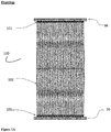
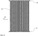
- In the specification, the terms "upper manifold" and "lower manifold" should be understood to mean gas manifolds which are equipped with ports designed to receive the shaped element connectors, which are attached to each end of the bunches of membranes. In addition, bunches of membranes may be potted directly into the upper and lower gas manifolds to form a continuous bunch of membranes stretching from one end of the manifold to the other (see
Figure 1B ). When oriented vertically the top manifold is referred to as the upper manifold and the bottom manifold is referred to as the lower manifold. The upper and lower manifolds are in fluid communication with the internal architecture of all the hollow fibres such that air/gas can flow from the inside of the upper manifold, through the hollow fibres to the lower manifold, or vice versa. - In the specification, the term "cassette" should be understood to mean a linear arrangement of potted hollow fibre membranes, comprising an upper and lower manifold into which are potted a large number of hollow fibre membranes or a number of bunches of hollow fibre membranes. A cassette is illustrated in
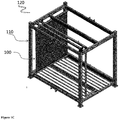
Figures 1A and1B . If gas is supplied to the upper manifold, then this manifold serves as the inlet manifold and the gas will flow downwards within the hollow fibres and into the lower manifold, which will serve as the exhaust gas manifold. If, however, the gas is supplied to the lower manifold, then this manifold serves as the inlet manifold and the gas will flow upwards within the hollow fibres and into the upper manifold, which will serve as the exhaust gas manifold. In the specification, the term "membrane module" or "Membrane Aerated Biofilm Reactor (MABR)" should be understood to mean a device into which a number (2-1,000, 2-900, 2-800, 2-750, 2-700, 2-650, 2-600, 2-550, 2-500, 2-450, 2-400, 2-350, 2-300, 2-250, 2-200, 2-150, 2-100, 2-50) of cassettes consisting of hollow fibre membranes can be secured in parallel. The cassettes are generally secured in a frame. - In the specification, the term "frame" in the context of use with a membrane module should be understood to mean a housing that is capable of receiving 2-1,000, 2-900, 2-800, 2-750, 2-700, 2-650, 2-600, 2-55, 2-500, 2-450, 2-400, 2-350, 2-300, 2-250, 2-200, 2-150, 2-100, 2-50 cassettes and hold them in parallel with a well-defined and even spacing between adjacent cassettes. Preferably, 2-200 cassettes are typically arranged within a frame. A frame is illustrated in
Figure 1C . - In the specification, the term "enclosed membrane module" should be understood to mean a membrane module which is open at the top and bottom but which is encased with an enclosure system as illustrated in
Figure 2 . - In the specification, the term "enclosure system" or "modular enclosure system" should be understood to mean a series of panels that can be attached to the frame of a membrane module (see
Figure 2 ) or can be arranged to form an enclosed frame for a membrane module. The panels of the enclosure system may incorporate enclosed channels, or conduits for water flow. When water is encouraged to flow through these channels or conduits, they induce a vertical water velocity past the membranes in the enclosed membrane module. The enclosure can be modular in nature and designed to permit the stacking of enclosed membrane modules to form a continuous enclosed volume consisting of several levels of membrane cassettes. The panels may also extend vertically above the upper manifold and extending beyond the surface of the water within the system. This arrangement separates the water inside the enclosed membrane module from the water outside of the enclosed membrane module. - In specification, the term "enclosed channel" should be understood to mean a fully enclosed conduit or pipe that is either moulded to or attached to the panels forming the enclosure of the invention. The enclosed channel may have a square, rectangular, triangular, hexagonal, other polygonal or circular cross-section.
- In the specification, the term "modular collar" should be understood to mean a tightly fitted enclosure that extends the height of the panels of the enclosed membrane module (encased by the enclosure of the invention) vertically by 100 mm to 500 mm above, and preferably 100 mm-1000 mm above the upper manifold and extending beyond the surface of the liquid. It separates the liquid inside the enclosed membrane module from the liquid outside of the enclosed membrane module.
- In the specification, the term "downcomer" should be understood to mean a vertical, enclosed channel that is moulded into, or attached to, a panel of the enclosed membrane module. The top of this downcomer is located beneath the surface of the liquid, and liquid within the downcomer flows in a downwards direction.
- In the specification, the term "airlift channel" should be understood to mean a vertical enclosed channel that is normally filled with liquid, installed below the surface of the liquid, such as wastewater, or protruding above the surface of the liquid. Air is introduced continuously, or in a pulsatile fashion, through the walls of a vertical, enclosed channel at a point that is approximately 0.5 m to 3 m below the liquid (wastewater) surface level in the bioreactor. The rising bubbles, formed and released within the enclosed channel rise and encourage an upwards flow of liquid (wastewater) within the enclosed channel. The air may be injected into the airlift channel using a variety of injection methods including: radial, axial, dual radial and axial, and swirl, under both steady and pulsating injection modes. In the steady air injection regime, the results have shown that dual injection outperforms axial and radial injections, and that the volumetric flow rate of liquid was improved by pulsatile air injection. Pulsatile air injection may be affected by either stopping and starting the air flow, either by means of solenoid valves or by the use of an air syphon. The design of a pulsatile air injection method using an air syphon is described in detail in
US Patent 6,162,020 . - In the specification, the term "substantially U-shaped tube" should be understood to mean two vertically aligned enclosed channels, fabricated into, or attached to a sidewall of the enclosure system: one channel being a downcomer and one channel being an airlift channel. The two vertical channels are connected by a U-bend, or a substantially U-shaped bend connector, at the base. One of the upper ends of the substantially U-shaped tube is open towards the enclosed module (within the modular collar and usually the downcomer, but it can also be the airlift channel) and the other upper end of the substantially U-shaped tube is open to the area outside of the modular collar (usually the airlift channel, but it can also be the downcomer).
- In the specification, the term "substantially W-shaped tube" should be understood to mean three vertically aligned enclosed channels, fabricated into, or attached to a sidewall of the enclosure system: two channels being a first and second downcomer and one channel being an airlift channel. The three vertical channels are aligned adjacent to each other and connected by a U-bend, or a substantially U-shaped bend connector, at the base. One of the upper ends of the substantially W-shaped tube is open towards the enclosed module (within the modular collar and is usually considered to be the airlift channel). The other upper ends of the substantially W-shaped tube are open to the area outside of the modular collar (usually considered to be the first and second downcomer channels). The order of the airlift channel and first and second downcomer as they appear in the W-shaped tube can vary according to the user's preference.
- In the specification, the term "airlift pump" should be understood to mean a system comprising a substantially U-shaped tube with air being injected into the base of one of the vertical channels of the substantially U-shaped tube to induce a flow of liquid through the substantially U-shaped tube. The rising air bubbles will induce an upwards flow of liquid above the point of air injection in the airlift channel, causing a corresponding downflow of liquid in the other vertical channel of the substantially U-shaped tube (the first downcomer). A similar arrangement can be made for a system having a substantially W-shaped tube, with air being injected into the base of one of the vertical channels of the substantially W-shaped tube to induce a flow of liquid through the substantially W-shaped tube. The rising air bubbles will induce an upwards flow of liquid above the point of air injection in the airlift channel, causing a corresponding downflow of liquid in one or both of the other vertical channels of the substantially W-shaped tube (the first and/or second downcomer).
- In the specification, the term "air syphon" should be understood to mean a syphon of the type described in
US Patent 6,162,020 which incorporates an air reservoir that is filled continuously with air but which discharges the air to an injection port in the airlift channel periodically when the volume of air is sufficient to create a syphon. - In the specification, the term "vertical return channel" should be understood to mean a continuous channel from the top of an enclosed membrane module to the base of the enclosed membrane module, or to the base of the lowest enclosed membrane module if the modules are stacked. The vertical return channel allows liquid to flow between the top of the enclosed membrane module to the base of the tank in which the modules are installed. The direction of flow will depend upon the operating mode of the airlift pump. Alternatively, it allows treated liquid from the top of the enclosed membrane module to be pumped to the bottom of the tank through the airlift pump.
- In the specification, the term "tank", "holding tank" or "bioreactor" should be understood to mean a large holding vessel, which is supplied with liquid (water or wastewater) and is used to hold the water or wastewater while it is being treated. One or more enclosed membrane modules may be installed within the tank to create a Membrane Aerated Biofilm Reactor (MABR).
- In the specification, the term "liquid" should be understood to mean "water" or "wastewater", which should be understood to mean any water that has been adversely affected in quality by anthropogenic influence. Wastewater can originate from a combination of domestic (for example, sewage), industrial, commercial or agricultural activities, surface runoff or storm-water, and from sewer inflow or infiltration.
- The invention will be more clearly understood from the following description of an embodiment thereof, given by way of example only, with reference to the accompanying drawings, in which:-
-
Figure 1A illustrates a cassette of the prior art comprising shaped elements with individual bundles of fibres, whileFigure 1B illustrates a cassette of the prior art in which the membranes are potted continuously directly into the upper and lower manifolds and which require no shaped element connectors.Figure 1C illustrates an elevation view of the membrane cassettes within a metal frame of the prior art that form a membrane module. -
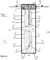
Figure 2A illustrates a side elevation view of an enclosed membrane module of the present invention andFigure 2B illustrates a side elevation view of the enclosed membrane module of the present invention, showing an integrated airlift system comprising an airlift pump, a first downcomer and a return channel. These membrane modules are completely surrounded and protected by the enclosure's panels, but are open at the top and the bottom.Figure 2C illustrates a plan view of an enclosed membrane module of present invention. -
Figure 3A illustrates a side elevation of an enclosed membrane module of the present invention, which has been fitted with a modular collar and installed in a holding tank or bioreactor (not shown).Figure 3B shows that if the liquid (water) level within the modular collar is higher than the surrounding liquid (water) level in the tank, the direction of flow is reversed when compared to the direction of flow inFigure 3A . -
Figure 4A andFigure 4B illustrate how the airlift mixing system provided on a panel of the enclosure system of the invention that can operate as an airlift pump. The airlift mixing system is capable of providing a flow from the upper headspace to the tank or a flow from the tank to the upper headspace, thus inducing an upward or a downward liquid flow, respectively, within the enclosed membrane module of the present invention. InFigure 4A , the intake port of the airlift mixing system is located within the modular collar and draws liquid from within the enclosed membrane module. The airlift channel discharges liquid outside of the modular collar and liquid may flow downwards through the return channel to the base of the tank within which the entire enclosed membrane module is located. InFigure 4B , the air injection port is located in the enclosed channel of the other side of the U-shaped tube that forms the airlift mixing system (now the upward flowing channel), and the discharge point of the airlift channel is now located within the modular collar and delivers liquid to the upper headspace above the membranes thus creating a higher liquid level within the enclosed module and forcing a downward velocity of liquid. The liquid within the tank is now drawn up from the bottom of the tank through the return channel or in via opening atpoint 12. The intake port of the first downcomer and return channel is now located outside of enclosed membrane module. -
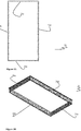
Figure 5A and Figure 5B show a plan view and side elevation view of the modular collar that is attached to the top of the enclosed membrane module of the present invention or to the top of the uppermost membrane module in a stack. -
Figure 6A andFigure 6B illustrate how the enclosed membrane modules of the present invention may be stacked within a tank.Figure 6A andFigure 6B are operating in the modes shown inFigures 4A and4B respectively. -
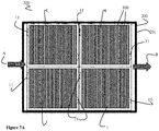
Figure 7A andFigure 7B illustrate a plan view and side view in cross section of four membrane modules each enclosed by a framing system of the present invention and which are installed in a tank. The whole treatment system makes up Membrane Aerated Biofilm Reactor which treats inlet wastewater and discharges a treated effluent. -
Figure 8 illustrates an enclosed membrane module with a liquid flow distribution means in situ in theupper headspace 104 of the enclosed membrane module. -
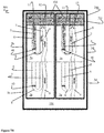
Figure 9A and 9B illustrate a side and front view of an airlift mixing system of the present invention, wherein the airlift mixing system is a substantially W-shape.Figure 9C illustrates the substantially W-shaped airlift mixing system in an enclosed membrane module of the present invention. - The invention described herein provides low shear conditions, and the effective delivery of substrates to the biofilms growing on membranes, by providing a low pressure, airlift mixing system, which is integrated into a membrane module enclosed by the enclosure system of the invention and that surrounds the membranes.
- Typically, airlift channels are feasible if the pressure against which the water must be pumped is less than about 300 mm of water. Pressure drops of more than 300 mm of water reduce the efficiency of airlift pumping and the water flow rate drops dramatically. For this reason, it is important that the head losses and pressure drops within the airlift mixing system itself are minimized. The size of the pipes or channels used for the airlift mixing system must be selected to minimize pressure losses and maximize airflow rates.
- The flow rate of liquid that can be achieved in an airlift mixing system is a function of the air flow rate, the depth of the air injection port and the size (effective diameter) of the airlift channel. Typically, the liquid flow rate increases with air flow rate and the depth of the air injection port. Since energy consumption is a major environmental concern and operating cost associated with wastewater treatment, it is important to minimize the energy requirements for mixing and aeration. This can be accomplished by using the air supplied to the membranes for both oxygen transfer and mixing. Also, by using an airlift mixing system with a shallow depth for the air injection port, the air pressure required within the membranes can be kept low and energy consumption can be minimized. The liquid flow rate through an enclosed membrane module can thus be controlled by the design and operating conditions of the airlift mixing system, while the operating air pressure is independent of the depth of submergence of the membranes in stacked membrane modules and only dependant on the depth of the air injection into the airlift mixing system.
- Referring now to the figures, where
Figure 1 illustrates acassette 100 comprising shapedelement connectors 101 with individual bundles offibres 102, potted into upper 98 and lower 99 manifolds whileFigure 1B illustrates acassette 100 in which themembrane fibres 102 are potted continuously and directly into the upper 98 and lower 99 manifolds and which require noshaped element connectors 101.Figure 1C illustrates a view ofmembrane cassettes 100, being assembled into amembrane module 120 of the prior art. Themembrane module 120 comprises aframe 110 into which thecassettes 100 can be fitted. - Referring now to
Figure 2 , where a general embodiment of the present invention is illustrated. Specifically,Figure 2A illustrates a side elevation view of a membrane module enclosed by the enclosure system of the present invention to form an enclosed membrane module, with the enclosed membrane module generally referred to byreference numeral 1. Theenclosed membrane module 1 comprisespanels membrane module 120, and comprise an airlift mixing system 4 (seeFigure 2B ). When in use with themembrane module 120, thepanels enclosed membrane module 1 completely surround and encloses thecassettes 100, but theenclosed membrane module 1 is open at the top and the bottom.Figure 2B illustrates a side elevation view of theenclosed membrane module 1, showing the airlift mixing system 4. In the illustrated embodiment, the airlift mixing system 4 is integrated within thepanels panels U-shaped tube 5 with a vertical tube attached thereto. Specifically, the substantiallyU-shaped tube 5 comprises afirst downcomer 6 connected to anairlift channel 7 by au-bend 8. Additionally, the system may comprise areturn channel 9. Theenclosed membrane module 1 is shown to further comprise a reinforcingbar 10 andports bar 10 extends frompanel 3a to theopposite panel 3c. Amodular collar 20 is attached to the top of theenclosed membrane module 1, and is configured to separate theports upper headspace 104 to alower headspace 106, theport 12 provides fluid communication between liquid in the tank and theupper headspace 104 through the substantiallyU-shaped tube 5. When liquid is flowing from the lower headspace 106 (or from the bottom of a holding tank) to theupper headspace 104, theport 11 provides fluid communication between the upper headspace and the liquid in the bulk tank through the substantiallyU-shaped tube 5. Theport 12 allows for air injected into theairlift channel 7 to escape to atmosphere, and not to become entrained in the liquid flowing downward in thereturn channel 9 to the bottom of the tank. -
Figure 2C illustrates a plan view of anenclosed membrane module 1. As illustrated, theupper headspace 104 of theenclosed membrane module 1 and a series ofparallel membrane cassettes 100 are visible. Thecassettes 100 are arranged in parallel that provide space between eachcassette 100 to allow liquid to flow there between. -
Figure 3A illustrates a side elevation of anenclosed membrane module 1, which has been fitted with themodular collar 20 and installed in a holding tank orbioreactor 200. When the level of liquid inside themodular collar 20 is below the liquid level in the surroundingtank 200, liquid will flow upwards through theenclosed membrane module 1 to equalize the water levels inside and outside of thetank 200. The greater the difference in liquid level between the outside and inside of the modular collar 20 (h mm of liquid as shown inFigure 3A ), the greater the induced liquid velocity through theenclosed membrane module 1.Figure 3B shows that if the liquid level within themodular collar 20 is higher than the surrounding liquid level in thetank 200, the direction of flow is reversed. Again, the greater the difference in liquid levels (h), the greater the liquid velocity created within the enclosed membrane module. The arrows inFigure 3A and 3B illustrate the direction of liquid flow induced by the changes in levels of liquid within themembrane module 120 and thetank 200. -
Figure 4A andFigure 4B illustrates the detail of the airlift mixing system 4 within apanel enclosed membrane module 1. The airlift mixing system 4 comprises the enclosed substantiallyU-shaped tube 5 connected to thevertical return channel 9 at one side thereof. InFigure 4A , the configuration of the channels of the airlift mixing system 4 is shown which illustrate movement of liquid from the bottom of thetank 200 to the top of theenclosed membrane module 1. In this instance, the outer enclosed channel of the airlift mixing system 4 acts as afirst downcomer 6, which receives liquid from inside the modular collar 20 (from the upper headspace 104) and acts to reduce the liquid level within themodular collar 20 relative to the liquid level within thetank 200. Air is injected into a middle-enclosed channel, here called theairlift pump 7, via anair injection port 40. The rising bubbles produced by theair injection port 40 induce a vertical liquid velocity flow (indicated by Arrow A), which moves water as illustrated by the arrows shown. At the top of theenclosed membrane module 1, theairlift pump 7 and thereturn channel 9 merge outside of theenclosed membrane module 1, the air bubbles are vented at the liquid surface and the liquid flows downwards through thereturn channel 9 to the base of thetank 200. InFigure 4B , the configuration of the channels of the airlift mixing system 4 is shown which illustrate movement of liquid from theupper manifold 104 within theenclosed membrane module 1 downwards through thecassettes 100 to the bottom of thetank 200. Theair injection port 40 is switched to the outer channel of the substantiallyU-shaped tube 5 and becomes theairlift pump 7, while the inner channel of the substantiallyU-shaped tube 5 becomes thefirst downcomer 6 and is physically connected to thereturn channel 9. Theairlift channel 7 supplies liquid to the inside of themodular collar 20 andupper manifold 104, causing an increase in water level above themembrane module 120 relative to the liquid outside of themodular collar 20 in thetank 200. In this operating mode, liquid is drawn from the bottom of thetank 200 via thereturn channel 9 as illustrated. The arrows A inFigure 4B illustrate the direction of liquid flow induced by theairlift channel 7. - The liquid level in the
modular collar 20 covering theenclosed membrane module 1 is separated from the liquid outside in thetank 200 in which the module is immersed due to the seal created by theenclosed membrane module 1, such that the airlift mixing system 4 may raise or lower the liquid level covering themembrane module 1 relative to the liquid level in thetank 200. -
Figure 5A and Figure 5B show a plan view and side elevation view of themodular collar 20 that is attached to the top of theenclosed membrane module 1. Themodular collar 20 comprises sides 21a,21b,21c,21d and is configured to fit to aframe 110 of amembrane module 120 or to the top of anenclosed membrane module 1, thus providing anupper headspace 104 with an increased height when compared toupper headspace 104 without amodular collar 20 in place. When in use, themodular collar 20 is configured to separate theports -
Figure 6A andFigure 6B illustrate how a number ofenclosed membrane modules 1,1' may be stacked one upon the other within atank 200. The stackedenclosed membrane modules 1,1' are configured such that thereturn channel 9 ofmodule 1 connects to the return channel 9' of the module 1'.Figure 6A andFigure 6B are operating in the modes shown inFigures 4A and4B , respectively. The substantially U-shaped tube 5' of module 1' is cut off by the insertion of abaffle 22 and remains unused. In the embodiment shown inFigure 6A , the liquid level outside themodular collar 20 of theenclosed membrane module 1 is higher than the liquid level inside themodular collar 20, thus creating an upward velocity of liquid from the bottom of thetank 200 to theupper headspace 104 of theenclosed membrane module 1. In the embodiment show inFigure 6B , the liquid level outside themodular collar 20 of themembrane module 1 is lower than the liquid level inside themodular collar 20, thus creating a downward velocity of liquid from theupper headspace 104 of theenclosed membrane module 1 to the bottom of thetank 200. -
Figure 7A andFigure 7B illustrate a plan view and side view in cross section of fourenclosed membrane modules 1, which are installed in atank 200 to form atreatment system 300. Thewhole treatment system 300 makes up a MABR, which treats inlet wastewater and discharges a treated effluent. Thetreatment system 300 comprises thetank 200 having ahousing 201 and a series of stackedenclosed membrane modules 1. In the embodiment show inFigure 7B , the liquid level outside themodular collar 20 in thetank 200 is lower than the liquid level inside the modular collar 20 (indicated by the h mm), thus creating a downward velocity of liquid from theupper manifold 104 of theenclosed membrane module 1 to the bottom of thetank 200. - In
Figure 7A and7B , liquid (water or wastewater (effluent)) enters thesystem 300 via an inlet waste pipe A and the treated effluent exits thesystem 300 via outlet B. The liquid is treated by interacting with thecassettes 100 of theenclosed membrane modules 1. The airlift mixing system 4 provides a low-pressure, low-energy mixing system that ensures there is effective contact between as much of the membrane-attached pollutant-degrading biofilm that accumulates on themembranes 102 and the pollutant-rich wastewater to be treated. Generally, theenclosed membrane module 1 is designed to operate with gas pressures inside thehollow membrane fibres 102 which may be higher or lower than the external hydrostatic pressure of thetank 200. - In
Figure 8 , theenclosed membrane module 1 is illustrated with a liquid flow distribution means 60 is shown in situ in theupper headspace 104 of theenclosed membrane module 1. Generally, the water flow distribution means 60 is in fluid communication withport 12 and is configured to ensure uniform flow through theenclosed membrane module 1, that is the velocity of the flow of liquid within the module is equal on a horizontal plane. The provision of a uniform liquid flow through theenclosed membrane module 1 ensures an even upflow liquid velocity throughout themembrane module 1 and prevents short circuiting of the liquid between theport 12 and bottom of thereturn channel 9. The uniform velocity ensures that all of the membrane supported biofilm is contacted by the wastewater and removes the creation of a dead zone or poorly mixed regions where no flow occurs. - In
Figure 9A-C , the airlift mixing system 4 is shown to contain asecond downcomer 6a giving the airlift mixing system 4 a substantially W-shape, where the central vertical channel is the air-lift channel 7 in fluid communication with thefirst downcomer 6 andsecond downcomer 6a on either side thereof. The air is delivered into thecentral airlift channel 7 at theair injection port 40, while the vertical channels, the first andsecond downcomer air lift channel 7 by acommon water manifold 8a along the bottom, thus forming a substantially W-shape tube 50. Due to the water and air mixture flowing upwards through the centralvertical channel 7, a downward waterflow is induced in both the first andsecond downcomer panels Figure 9C ), which extend beyond the surface of the liquid, the liquid discharged through theport 11 and the flow distribution means 60, originating from theairlift channel 7, must flow vertically downward and out of theenclosed membrane module 1 through the open bottom. One of the advantages of the W-shaped mixing system is that there are two inlets to the downcomers in this configuration and liquid can be introduced into the W-Shaped mixing system from two different points in tank. In the preferred configuration if the flow of liquid in the W-shaped tube is to be reversed, then air must be introduced into both vertical channels either side of the central vertical channel to make sure both of the side vertical channels become airlift channels and the central vertical channel becomes the downcomer. The W-shaped airlift mixing system can also be stacked as shown inFigure 6A andFigure 6B , one or two vertical return channels can also be installed on either side of the W-shaped mixing system. The W-shaped mixing system is easy to retrofit to existing modules, and can provide for larger area for flow using vertical channels with a smaller cross section. - One of the advantages of the invention is that the enclosed membrane module both protects the membranes from damage during transit and incorporates a low-pressure airlift system to encourage good liquid flow through the membrane module when the modules are installed in a bioreactor. This means that the effectiveness of the MABR when installed into a large tank is not dependant on the tank mixing, but is independently controlled via the liquid velocity in the enclosed membrane module. Such independent control allows successful installation in tanks of varying depth and shape or which were previously designed for different purposes, e.g. settling tanks, can be upgraded to incorporate the MABR without the need for an installation of an independent mixing system.
- In the specification, the terms "comprise, comprises, comprised and comprising" or any variation thereof and the terms "include, includes, included and including" or any variation thereof are considered to be totally interchangeable and they should all be afforded the widest possible interpretation and vice versa.
Claims (14)
- An enclosure system for use with a membrane module (120) in membrane supported biofilm reactors, the membrane module (120) of the type having an upper and lower headspace (104,106) separated by an array of gas-permeable hollow fibre membrane cassettes (100) secured in parallel in the module (120), wherein the cassettes (100) are a linear arrangement of potted hollow fibre membranes, comprising an upper and lower manifold (98,99) into which are potted a large number of hollow fibre membranes or a number of bunches of hollow fibre membranes (102), characterised in that the enclosure system comprises:(i) a plurality of panels (3a,3b,3c,3d) configured to seal the membrane module (120) to form an enclosed membrane module (1) which is open at the top and bottom but which is encased within the enclosure system;(ii) a modular collar (20) configured to attach vertically to the enclosed membrane module (1), increasing the height of the upper headspace (104); and(iii) a low-pressure airlift mixing system (4), which is integrated into at least one panel of said plurality of panels (3a,3b,3c,3d), which is configured to transport liquid either from inside the membrane module (120) to outside of the membrane module (120), or vice versa, so that liquid is pumped in an upward or downward direction through the enclosed membrane module (1), to encourage good liquid flow through the enclosed membrane module (120) when it is installed in a bioreactor tank (200), wherein the airlift mixing system (4) comprises:an airlift channel (7) and a first downcomer (6), which are in fluid communication with each other at their bottom, forming two sides of a substantially U-shaped tube (5) which is open at both ends;a vertical return channel (9) having its top in fluid communication with the top of the channel of the substantially U-shaped tube (5) proximal the vertical return channel (9); andan air injection port (40) configured to accept and deliver air into the base of the airlift channel (7) to induce upward flow of liquid above the air injection port (40) in the airlift channel (7), causing a corresponding downward flow of liquid in the first downcomer (6); andwherein the open end of the U-shaped tube (5) distal the vertical return channel (7) forms a port (11) with access to inside the enclosed membrane module (1), the open end of the U-shaped tube (5) proximal the vertical return channel (7) forms a port (12) with access to outside of the enclosed membrane module (1) and the lower end of the vertical return channel (9) allows a fluid communication between the vertical return channel (9) and the bottom of said bioreactor or tank (200).
- An enclosure system according to Claim 1, in which the airlift mixing system further comprises a third vertical channel, giving the airlift mixing system a substantially W-shape, wherein the third vertical channel is a second downcomer (6a), and wherein one of the vertical channels is the air-lift channel (7), which is in fluid communication with the first and second downcomer (6,6a).
- An enclosure system according to Claim 1 or Claim 2, in which the vertical return channel (9) is open to the environment outside of the enclosed membrane module (1) and configured to provide a continuous channel to supply water from one location within the bioreactor or tank (200), or another holding tank or compartment within a treatment system.
- An enclosure system according to any one of Claims 2 or 3, in which the first and second downcomer (6,6a) is in fluid communication with liquid outside the enclosed membrane module (1) and the airlift channel (7) is in fluid communication with liquid inside of the enclosed membrane module (1).
- An enclosure system according to any one of Claims 1 to 4, in which the air that is supplied to the airlift channel (7) is sourced from either exhaust air from the membranes, supplemental air from an external source, or both.
- An enclosure system according to any one of Claims 1 to 5, in which the air injection port (40) is configured to release air continuously, in a pulsed or periodic manner, or a combination of both; and in which the air injection port (40) is optionally connected to an air syphon configured to allow air to accumulate and be released periodically to the air injection port (40).
- An enclosure system according to any one of Claims 1 to 6, in which the air injection port (40) is configured to introduce air axially, radially, both axially and radially, or at an angle so as to induce turbulent water flow within the airlift channel (7).
- An enclosure system according to any one of Claims 1 to 7, in which the air injection port (40) is 3.0 m or less below the liquid surface within the modular collar (20) of the enclosure system.
- An enclosure system according to any one of Claims 1 to 8, in which the airlift mixing system (4) is configured to control the level of liquid within the enclosed membrane module (1) relative to the level of liquid outside the enclosed membrane module (1).
- An enclosure system according to any one of Claims 1 to 9, in which at least one panel (3a,3b,3c,3d) in a four-sided enclosed membrane module (1) is configured to each accommodate the airlift mixing system (4).
- An enclosure system according to any one of Claims 1 to 10, in which at least two, three or all panels in a four-sided enclosed membrane module are each configured to accommodate the airlift mixing system.
- An enclosure system according to any one of Claims 1 to 11, further comprising a liquid flow distribution means in the headspace of the enclosed membrane module configured to provide uniform liquid flow through the enclosed membrane module (1).
- An enclosure system according to any one of Claims 1 to 12, in which the enclosure system is modular, and where a plurality of enclosed membrane modules (1) can be stacked one on top of the other.
- An enclosure system according to any one of Claims 1 to 13, in which the lower gas manifold (99) can be purged of liquid that may accumulate as a result of condensation or leakage; and in which a high air flow rate is optionally delivered to the lower manifold (99) either by increasing the airflow through the membranes, or by supplemental air supplied directly to the lower manifold (99), or a combination of both, so as to transport the accumulated liquid to either the airlift mixing system (4) or to the liquid surface..
Priority Applications (1)
| Application Number | Priority Date | Filing Date | Title |
|---|---|---|---|
| PL18709946T PL3582883T3 (en) | 2017-02-20 | 2018-02-20 | Enclosure system for use with a membrane module of a membrane aerated biofilm reactor and comprising a low pressure airlift mixing system |
Applications Claiming Priority (3)
| Application Number | Priority Date | Filing Date | Title |
|---|---|---|---|
| US201762461139P | 2017-02-20 | 2017-02-20 | |
| EP17156862 | 2017-02-20 | ||
| PCT/EP2018/054181 WO2018150055A1 (en) | 2017-02-20 | 2018-02-20 | A low-pressure, reversible airlift mixing system for use with a membrane aerated biofilm reactor |
Publications (2)
| Publication Number | Publication Date |
|---|---|
| EP3582883A1 EP3582883A1 (en) | 2019-12-25 |
| EP3582883B1 true EP3582883B1 (en) | 2021-05-12 |
Family
ID=61616952
Family Applications (1)
| Application Number | Title | Priority Date | Filing Date |
|---|---|---|---|
| EP18709946.0A Active EP3582883B1 (en) | 2017-02-20 | 2018-02-20 | Enclosure system for use with a membrane module of a membrane aerated biofilm reactor and comprising a low pressure airlift mixing system |
Country Status (10)
| Country | Link |
|---|---|
| US (1) | US11434155B2 (en) |
| EP (1) | EP3582883B1 (en) |
| JP (1) | JP7011671B2 (en) |
| CN (1) | CN110461448B (en) |
| BR (1) | BR112019017266A2 (en) |
| CA (1) | CA3052371A1 (en) |
| DK (1) | DK3582883T3 (en) |
| ES (1) | ES2884099T3 (en) |
| HU (1) | HUE056123T2 (en) |
| PL (1) | PL3582883T3 (en) |
Families Citing this family (5)
| Publication number | Priority date | Publication date | Assignee | Title |
|---|---|---|---|---|
| CN109231436B (en) * | 2018-11-06 | 2024-03-29 | 北京城市排水集团有限责任公司 | Sewage uniform distribution treatment device for aerobic granular sludge system and application method of sewage uniform distribution treatment device |
| GB2606128A (en) | 2021-03-03 | 2022-11-02 | Oxymem Ltd | Air flow control in a membrane aerated biofilm reactor |
| CN115353204A (en) * | 2022-09-08 | 2022-11-18 | 中国长江三峡集团有限公司 | Baffle treatment system |
| CN116715314A (en) * | 2023-06-05 | 2023-09-08 | 江苏立业环境科技有限公司 | Three-phase separator with anti-blocking function for petroleum sewage |
| CN117228860B (en) * | 2023-11-16 | 2024-01-23 | 成都凯亚美环保机械制造股份有限公司 | MABR membrane assembly, membrane structure and sewage treatment system using same |
Family Cites Families (13)
| Publication number | Priority date | Publication date | Assignee | Title |
|---|---|---|---|---|
| NL9302260A (en) * | 1993-12-24 | 1995-07-17 | Stork Friesland Bv | Membrane bioreactor with gas-lift system. |
| FR2760197B1 (en) * | 1997-02-28 | 1999-03-26 | Commissariat Energie Atomique | DEVICE FOR BREWING THE CONTENT OF A TANK COMPRISING A BUBBLE ELEVATOR |
| JP2000051664A (en) | 1998-08-10 | 2000-02-22 | Sekisui Chem Co Ltd | Treated water filter apparatus and sewage purifying apparatus |
| CA2290053C (en) * | 1999-11-18 | 2009-10-20 | Zenon Environmental Inc. | Immersed membrane module and process |
| JP2000176252A (en) | 1998-12-14 | 2000-06-27 | Sekisui Chem Co Ltd | Filter device and purifying tank |
| DE10004863A1 (en) | 1999-08-04 | 2001-02-15 | Wehrle Werk Ag | Separation of solids and liquid from sludge suspension using high efficiency, low cost agitated filter, passes flow of suspended air bubbles tangentially and turbulently past loosely-held filter membrane |
| AU2002953111A0 (en) * | 2002-12-05 | 2002-12-19 | U. S. Filter Wastewater Group, Inc. | Mixing chamber |
| JP2006101805A (en) | 2004-10-07 | 2006-04-20 | Japan Organo Co Ltd | Hollow fiber membrane type bioreactor and liquid treatment method using the same |
| WO2008139618A1 (en) * | 2007-05-14 | 2008-11-20 | Mitsubishi Rayon Engineering Co., Ltd. | Method of water disposal |
| EP2192379A1 (en) | 2008-11-27 | 2010-06-02 | University College Dublin, National University of Ireland Dublin | Determining biofilm thickness in a membrane supported biofilm reactor |
| DE102011122695B4 (en) * | 2011-12-23 | 2013-09-05 | Birgit Prädel | Clear water compressed air lift for biological wastewater treatment plants and process for its operation |
| CN102826652A (en) * | 2012-01-13 | 2012-12-19 | 北京海思清膜科技有限公司 | Inner-aeration hollow fiber film carrier module and its application method |
| EP3114091A1 (en) | 2014-03-04 | 2017-01-11 | OxyMem Limited | A membrane aerated biofilm reactor (mabr) |
-
2018
- 2018-02-20 PL PL18709946T patent/PL3582883T3/en unknown
- 2018-02-20 JP JP2019565982A patent/JP7011671B2/en active Active
- 2018-02-20 US US16/487,281 patent/US11434155B2/en active Active
- 2018-02-20 BR BR112019017266A patent/BR112019017266A2/en active Search and Examination
- 2018-02-20 EP EP18709946.0A patent/EP3582883B1/en active Active
- 2018-02-20 CA CA3052371A patent/CA3052371A1/en active Pending
- 2018-02-20 CN CN201880012853.3A patent/CN110461448B/en active Active
- 2018-02-20 DK DK18709946.0T patent/DK3582883T3/en active
- 2018-02-20 HU HUE18709946A patent/HUE056123T2/en unknown
- 2018-02-20 ES ES18709946T patent/ES2884099T3/en active Active
Non-Patent Citations (1)
| Title |
|---|
| None * |
Also Published As
| Publication number | Publication date |
|---|---|
| US11434155B2 (en) | 2022-09-06 |
| CA3052371A1 (en) | 2018-08-23 |
| EP3582883A1 (en) | 2019-12-25 |
| ES2884099T3 (en) | 2021-12-10 |
| BR112019017266A2 (en) | 2020-04-14 |
| US20210139359A1 (en) | 2021-05-13 |
| PL3582883T3 (en) | 2022-02-14 |
| DK3582883T3 (en) | 2021-08-09 |
| JP7011671B2 (en) | 2022-01-26 |
| HUE056123T2 (en) | 2022-01-28 |
| CN110461448A (en) | 2019-11-15 |
| CN110461448B (en) | 2022-05-24 |
| JP2020508215A (en) | 2020-03-19 |
Similar Documents
| Publication | Publication Date | Title |
|---|---|---|
| EP3582883B1 (en) | Enclosure system for use with a membrane module of a membrane aerated biofilm reactor and comprising a low pressure airlift mixing system | |
| US10273174B2 (en) | Membrane aerated biofilm reactor (MABR) | |
| US7481933B2 (en) | Process to improve the efficiency of a membrane filter activated sludge system | |
| US7713413B2 (en) | Aerated anoxic membrane bioreactor | |
| US7892433B2 (en) | Wastewater treatment system | |
| RU2446866C2 (en) | Method of mixing and/or aeration of fluids, particularly, effluents by, particularly, drowned aerator | |
| US6780318B2 (en) | Method for recovering a disposal trench with a biomat slime, and method for operating a waste treatment vessel | |
| WO2018150055A1 (en) | A low-pressure, reversible airlift mixing system for use with a membrane aerated biofilm reactor | |
| EP3095507A1 (en) | Membrane connector to promote mass transfer in a membrane aerated biofilm reactor (mabr) | |
| KR100274539B1 (en) | Waste Water Treatment Methods and Fixed Bed Type Biofilm Media for Liquied Separation from MLSS & Nitrogen/Phosphorous Removal | |
| JP2012000584A (en) | Air lift pump apparatus and wastewater treatment facility | |
| JP7220740B2 (en) | MEMBRANE ACTIVATED SLUDGE TREATMENT APPARATUS AND MEMBRANE ACTIVATED SLUDGE TREATMENT METHOD | |
| JP7121823B2 (en) | Membrane separation activated sludge treatment device, membrane separation activated sludge treatment method and raw water supply device | |
| JP2017205734A (en) | Waste water treatment device | |
| JPH0631288A (en) | Septic tank | |
| UA28510U (en) | Purifying construction for waste water biological treatment |
Legal Events
| Date | Code | Title | Description |
|---|---|---|---|
| STAA | Information on the status of an ep patent application or granted ep patent |
Free format text: STATUS: UNKNOWN |
|
| STAA | Information on the status of an ep patent application or granted ep patent |
Free format text: STATUS: THE INTERNATIONAL PUBLICATION HAS BEEN MADE |
|
| PUAI | Public reference made under article 153(3) epc to a published international application that has entered the european phase |
Free format text: ORIGINAL CODE: 0009012 |
|
| STAA | Information on the status of an ep patent application or granted ep patent |
Free format text: STATUS: REQUEST FOR EXAMINATION WAS MADE |
|
| 17P | Request for examination filed |
Effective date: 20190916 |
|
| AK | Designated contracting states |
Kind code of ref document: A1 Designated state(s): AL AT BE BG CH CY CZ DE DK EE ES FI FR GB GR HR HU IE IS IT LI LT LU LV MC MK MT NL NO PL PT RO RS SE SI SK SM TR |
|
| AX | Request for extension of the european patent |
Extension state: BA ME |
|
| DAV | Request for validation of the european patent (deleted) | ||
| DAX | Request for extension of the european patent (deleted) | ||
| STAA | Information on the status of an ep patent application or granted ep patent |
Free format text: STATUS: EXAMINATION IS IN PROGRESS |
|
| 17Q | First examination report despatched |
Effective date: 20200702 |
|
| GRAP | Despatch of communication of intention to grant a patent |
Free format text: ORIGINAL CODE: EPIDOSNIGR1 |
|
| STAA | Information on the status of an ep patent application or granted ep patent |
Free format text: STATUS: GRANT OF PATENT IS INTENDED |
|
| INTG | Intention to grant announced |
Effective date: 20201201 |
|
| GRAS | Grant fee paid |
Free format text: ORIGINAL CODE: EPIDOSNIGR3 |
|
| GRAA | (expected) grant |
Free format text: ORIGINAL CODE: 0009210 |
|
| STAA | Information on the status of an ep patent application or granted ep patent |
Free format text: STATUS: THE PATENT HAS BEEN GRANTED |
|
| AK | Designated contracting states |
Kind code of ref document: B1 Designated state(s): AL AT BE BG CH CY CZ DE DK EE ES FI FR GB GR HR HU IE IS IT LI LT LU LV MC MK MT NL NO PL PT RO RS SE SI SK SM TR |
|
| REG | Reference to a national code |
Ref country code: GB Ref legal event code: FG4D |
|
| REG | Reference to a national code |
Ref country code: CH Ref legal event code: EP |
|
| REG | Reference to a national code |
Ref country code: DE Ref legal event code: R096 Ref document number: 602018017022 Country of ref document: DE |
|
| REG | Reference to a national code |
Ref country code: IE Ref legal event code: FG4D |
|
| REG | Reference to a national code |
Ref country code: AT Ref legal event code: REF Ref document number: 1391801 Country of ref document: AT Kind code of ref document: T Effective date: 20210615 |
|
| REG | Reference to a national code |
Ref country code: DK Ref legal event code: T3 Effective date: 20210802 |
|
| REG | Reference to a national code |
Ref country code: NL Ref legal event code: FP |
|
| REG | Reference to a national code |
Ref country code: SE Ref legal event code: TRGR |
|
| REG | Reference to a national code |
Ref country code: LT Ref legal event code: MG9D |
|
| REG | Reference to a national code |
Ref country code: AT Ref legal event code: MK05 Ref document number: 1391801 Country of ref document: AT Kind code of ref document: T Effective date: 20210512 |
|
| PG25 | Lapsed in a contracting state [announced via postgrant information from national office to epo] |
Ref country code: AT Free format text: LAPSE BECAUSE OF FAILURE TO SUBMIT A TRANSLATION OF THE DESCRIPTION OR TO PAY THE FEE WITHIN THE PRESCRIBED TIME-LIMIT Effective date: 20210512 Ref country code: BG Free format text: LAPSE BECAUSE OF FAILURE TO SUBMIT A TRANSLATION OF THE DESCRIPTION OR TO PAY THE FEE WITHIN THE PRESCRIBED TIME-LIMIT Effective date: 20210812 Ref country code: LT Free format text: LAPSE BECAUSE OF FAILURE TO SUBMIT A TRANSLATION OF THE DESCRIPTION OR TO PAY THE FEE WITHIN THE PRESCRIBED TIME-LIMIT Effective date: 20210512 Ref country code: HR Free format text: LAPSE BECAUSE OF FAILURE TO SUBMIT A TRANSLATION OF THE DESCRIPTION OR TO PAY THE FEE WITHIN THE PRESCRIBED TIME-LIMIT Effective date: 20210512 Ref country code: FI Free format text: LAPSE BECAUSE OF FAILURE TO SUBMIT A TRANSLATION OF THE DESCRIPTION OR TO PAY THE FEE WITHIN THE PRESCRIBED TIME-LIMIT Effective date: 20210512 |
|
| PG25 | Lapsed in a contracting state [announced via postgrant information from national office to epo] |
Ref country code: RS Free format text: LAPSE BECAUSE OF FAILURE TO SUBMIT A TRANSLATION OF THE DESCRIPTION OR TO PAY THE FEE WITHIN THE PRESCRIBED TIME-LIMIT Effective date: 20210512 Ref country code: LV Free format text: LAPSE BECAUSE OF FAILURE TO SUBMIT A TRANSLATION OF THE DESCRIPTION OR TO PAY THE FEE WITHIN THE PRESCRIBED TIME-LIMIT Effective date: 20210512 Ref country code: NO Free format text: LAPSE BECAUSE OF FAILURE TO SUBMIT A TRANSLATION OF THE DESCRIPTION OR TO PAY THE FEE WITHIN THE PRESCRIBED TIME-LIMIT Effective date: 20210812 Ref country code: PT Free format text: LAPSE BECAUSE OF FAILURE TO SUBMIT A TRANSLATION OF THE DESCRIPTION OR TO PAY THE FEE WITHIN THE PRESCRIBED TIME-LIMIT Effective date: 20210913 Ref country code: GR Free format text: LAPSE BECAUSE OF FAILURE TO SUBMIT A TRANSLATION OF THE DESCRIPTION OR TO PAY THE FEE WITHIN THE PRESCRIBED TIME-LIMIT Effective date: 20210813 Ref country code: IS Free format text: LAPSE BECAUSE OF FAILURE TO SUBMIT A TRANSLATION OF THE DESCRIPTION OR TO PAY THE FEE WITHIN THE PRESCRIBED TIME-LIMIT Effective date: 20210912 |
|
| REG | Reference to a national code |
Ref country code: ES Ref legal event code: FG2A Ref document number: 2884099 Country of ref document: ES Kind code of ref document: T3 Effective date: 20211210 |
|
| REG | Reference to a national code |
Ref country code: HU Ref legal event code: AG4A Ref document number: E056123 Country of ref document: HU |
|
| PG25 | Lapsed in a contracting state [announced via postgrant information from national office to epo] |
Ref country code: CZ Free format text: LAPSE BECAUSE OF FAILURE TO SUBMIT A TRANSLATION OF THE DESCRIPTION OR TO PAY THE FEE WITHIN THE PRESCRIBED TIME-LIMIT Effective date: 20210512 Ref country code: RO Free format text: LAPSE BECAUSE OF FAILURE TO SUBMIT A TRANSLATION OF THE DESCRIPTION OR TO PAY THE FEE WITHIN THE PRESCRIBED TIME-LIMIT Effective date: 20210512 Ref country code: EE Free format text: LAPSE BECAUSE OF FAILURE TO SUBMIT A TRANSLATION OF THE DESCRIPTION OR TO PAY THE FEE WITHIN THE PRESCRIBED TIME-LIMIT Effective date: 20210512 Ref country code: SM Free format text: LAPSE BECAUSE OF FAILURE TO SUBMIT A TRANSLATION OF THE DESCRIPTION OR TO PAY THE FEE WITHIN THE PRESCRIBED TIME-LIMIT Effective date: 20210512 Ref country code: SK Free format text: LAPSE BECAUSE OF FAILURE TO SUBMIT A TRANSLATION OF THE DESCRIPTION OR TO PAY THE FEE WITHIN THE PRESCRIBED TIME-LIMIT Effective date: 20210512 |
|
| REG | Reference to a national code |
Ref country code: DE Ref legal event code: R097 Ref document number: 602018017022 Country of ref document: DE |
|
| PLBE | No opposition filed within time limit |
Free format text: ORIGINAL CODE: 0009261 |
|
| STAA | Information on the status of an ep patent application or granted ep patent |
Free format text: STATUS: NO OPPOSITION FILED WITHIN TIME LIMIT |
|
| 26N | No opposition filed |
Effective date: 20220215 |
|
| PG25 | Lapsed in a contracting state [announced via postgrant information from national office to epo] |
Ref country code: IS Free format text: LAPSE BECAUSE OF FAILURE TO SUBMIT A TRANSLATION OF THE DESCRIPTION OR TO PAY THE FEE WITHIN THE PRESCRIBED TIME-LIMIT Effective date: 20210912 Ref country code: AL Free format text: LAPSE BECAUSE OF FAILURE TO SUBMIT A TRANSLATION OF THE DESCRIPTION OR TO PAY THE FEE WITHIN THE PRESCRIBED TIME-LIMIT Effective date: 20210512 |
|
| PG25 | Lapsed in a contracting state [announced via postgrant information from national office to epo] |
Ref country code: MC Free format text: LAPSE BECAUSE OF FAILURE TO SUBMIT A TRANSLATION OF THE DESCRIPTION OR TO PAY THE FEE WITHIN THE PRESCRIBED TIME-LIMIT Effective date: 20210512 |
|
| PG25 | Lapsed in a contracting state [announced via postgrant information from national office to epo] |
Ref country code: LU Free format text: LAPSE BECAUSE OF NON-PAYMENT OF DUE FEES Effective date: 20220220 |
|
| PGFP | Annual fee paid to national office [announced via postgrant information from national office to epo] |
Ref country code: IE Payment date: 20221202 Year of fee payment: 6 Ref country code: GB Payment date: 20221209 Year of fee payment: 6 |
|
| PGFP | Annual fee paid to national office [announced via postgrant information from national office to epo] |
Ref country code: NL Payment date: 20230220 Year of fee payment: 6 |
|
| PGFP | Annual fee paid to national office [announced via postgrant information from national office to epo] |
Ref country code: FR Payment date: 20230220 Year of fee payment: 6 Ref country code: ES Payment date: 20230317 Year of fee payment: 6 Ref country code: DK Payment date: 20230220 Year of fee payment: 6 Ref country code: CH Payment date: 20230307 Year of fee payment: 6 |
|
| PGFP | Annual fee paid to national office [announced via postgrant information from national office to epo] |
Ref country code: SE Payment date: 20230220 Year of fee payment: 6 Ref country code: PL Payment date: 20230209 Year of fee payment: 6 Ref country code: IT Payment date: 20230228 Year of fee payment: 6 Ref country code: HU Payment date: 20230216 Year of fee payment: 6 Ref country code: DE Payment date: 20230216 Year of fee payment: 6 Ref country code: BE Payment date: 20230220 Year of fee payment: 6 |
|
| P01 | Opt-out of the competence of the unified patent court (upc) registered |
Effective date: 20230530 |
|
| PGFP | Annual fee paid to national office [announced via postgrant information from national office to epo] |
Ref country code: NL Payment date: 20240108 Year of fee payment: 7 |
|
| PGFP | Annual fee paid to national office [announced via postgrant information from national office to epo] |
Ref country code: ES Payment date: 20240307 Year of fee payment: 7 Ref country code: IE Payment date: 20240103 Year of fee payment: 7 |