EP3582731B1 - Pansement à zones de contraction variable - Google Patents
Pansement à zones de contraction variable Download PDFInfo
- Publication number
- EP3582731B1 EP3582731B1 EP18707552.8A EP18707552A EP3582731B1 EP 3582731 B1 EP3582731 B1 EP 3582731B1 EP 18707552 A EP18707552 A EP 18707552A EP 3582731 B1 EP3582731 B1 EP 3582731B1
- Authority
- EP
- European Patent Office
- Prior art keywords
- contraction zone
- manifold
- tissue site
- dressing
- amount
- Prior art date
- Legal status (The legal status is an assumption and is not a legal conclusion. Google has not performed a legal analysis and makes no representation as to the accuracy of the status listed.)
- Active
Links
- 230000008602 contraction Effects 0.000 title claims description 110
- 238000007789 sealing Methods 0.000 claims description 38
- 239000012530 fluid Substances 0.000 claims description 31
- 239000006260 foam Substances 0.000 claims description 13
- 238000004891 communication Methods 0.000 claims description 8
- 239000007788 liquid Substances 0.000 claims description 4
- 230000004044 response Effects 0.000 claims description 4
- 210000001519 tissue Anatomy 0.000 description 113
- 239000010410 layer Substances 0.000 description 73
- 239000000463 material Substances 0.000 description 29
- 239000011148 porous material Substances 0.000 description 27
- 230000003014 reinforcing effect Effects 0.000 description 17
- 210000002615 epidermis Anatomy 0.000 description 15
- 239000000853 adhesive Substances 0.000 description 14
- 230000001070 adhesive effect Effects 0.000 description 14
- 206010052428 Wound Diseases 0.000 description 7
- 239000000499 gel Substances 0.000 description 7
- 238000012360 testing method Methods 0.000 description 7
- 208000027418 Wounds and injury Diseases 0.000 description 6
- 230000008901 benefit Effects 0.000 description 6
- 239000004814 polyurethane Substances 0.000 description 6
- 239000000126 substance Substances 0.000 description 6
- 238000002560 therapeutic procedure Methods 0.000 description 6
- 230000002745 absorbent Effects 0.000 description 5
- 239000002250 absorbent Substances 0.000 description 5
- 238000000034 method Methods 0.000 description 5
- 239000003522 acrylic cement Substances 0.000 description 4
- 238000000576 coating method Methods 0.000 description 4
- 229920002635 polyurethane Polymers 0.000 description 4
- 239000003566 sealing material Substances 0.000 description 4
- 239000013598 vector Substances 0.000 description 4
- 239000011248 coating agent Substances 0.000 description 3
- 238000001514 detection method Methods 0.000 description 3
- 230000000977 initiatory effect Effects 0.000 description 3
- 229920001296 polysiloxane Polymers 0.000 description 3
- 238000012546 transfer Methods 0.000 description 3
- GJCOSYZMQJWQCA-UHFFFAOYSA-N 9H-xanthene Chemical compound C1=CC=C2CC3=CC=CC=C3OC2=C1 GJCOSYZMQJWQCA-UHFFFAOYSA-N 0.000 description 2
- 244000007835 Cyamopsis tetragonoloba Species 0.000 description 2
- 239000004952 Polyamide Substances 0.000 description 2
- 239000004721 Polyphenylene oxide Substances 0.000 description 2
- 229920006397 acrylic thermoplastic Polymers 0.000 description 2
- 239000001913 cellulose Substances 0.000 description 2
- 229920002678 cellulose Polymers 0.000 description 2
- 238000011161 development Methods 0.000 description 2
- 229920001971 elastomer Polymers 0.000 description 2
- 239000000416 hydrocolloid Substances 0.000 description 2
- 230000006872 improvement Effects 0.000 description 2
- 238000005259 measurement Methods 0.000 description 2
- 239000012528 membrane Substances 0.000 description 2
- 238000012544 monitoring process Methods 0.000 description 2
- 206010033675 panniculitis Diseases 0.000 description 2
- 230000037361 pathway Effects 0.000 description 2
- 229920003229 poly(methyl methacrylate) Polymers 0.000 description 2
- 229920002647 polyamide Polymers 0.000 description 2
- 229920000728 polyester Polymers 0.000 description 2
- 229920000570 polyether Polymers 0.000 description 2
- 229920000642 polymer Polymers 0.000 description 2
- 230000008569 process Effects 0.000 description 2
- 239000005060 rubber Substances 0.000 description 2
- 229910052709 silver Inorganic materials 0.000 description 2
- 239000004332 silver Substances 0.000 description 2
- 210000004304 subcutaneous tissue Anatomy 0.000 description 2
- ISXSCDLOGDJUNJ-UHFFFAOYSA-N tert-butyl prop-2-enoate Chemical compound CC(C)(C)OC(=O)C=C ISXSCDLOGDJUNJ-UHFFFAOYSA-N 0.000 description 2
- 239000004753 textile Substances 0.000 description 2
- 230000037303 wrinkles Effects 0.000 description 2
- 229920001285 xanthan gum Polymers 0.000 description 2
- 229920002134 Carboxymethyl cellulose Polymers 0.000 description 1
- 229920002943 EPDM rubber Polymers 0.000 description 1
- 239000004593 Epoxy Substances 0.000 description 1
- 229920000181 Ethylene propylene rubber Polymers 0.000 description 1
- 206010063560 Excessive granulation tissue Diseases 0.000 description 1
- 244000043261 Hevea brasiliensis Species 0.000 description 1
- 229920000459 Nitrile rubber Polymers 0.000 description 1
- 239000005062 Polybutadiene Substances 0.000 description 1
- 229920002614 Polyether block amide Polymers 0.000 description 1
- 239000004372 Polyvinyl alcohol Substances 0.000 description 1
- 239000004820 Pressure-sensitive adhesive Substances 0.000 description 1
- 206010040830 Skin discomfort Diseases 0.000 description 1
- 206010040880 Skin irritation Diseases 0.000 description 1
- 238000010521 absorption reaction Methods 0.000 description 1
- 230000004075 alteration Effects 0.000 description 1
- 230000000845 anti-microbial effect Effects 0.000 description 1
- 239000004599 antimicrobial Substances 0.000 description 1
- 230000005540 biological transmission Effects 0.000 description 1
- 239000008280 blood Substances 0.000 description 1
- 210000004369 blood Anatomy 0.000 description 1
- 230000017531 blood circulation Effects 0.000 description 1
- JEDYYFXHPAIBGR-UHFFFAOYSA-N butafenacil Chemical compound O=C1N(C)C(C(F)(F)F)=CC(=O)N1C1=CC=C(Cl)C(C(=O)OC(C)(C)C(=O)OCC=C)=C1 JEDYYFXHPAIBGR-UHFFFAOYSA-N 0.000 description 1
- 229920005549 butyl rubber Polymers 0.000 description 1
- 210000004027 cell Anatomy 0.000 description 1
- 230000001413 cellular effect Effects 0.000 description 1
- 230000008859 change Effects 0.000 description 1
- 230000008878 coupling Effects 0.000 description 1
- 238000010168 coupling process Methods 0.000 description 1
- 238000005859 coupling reaction Methods 0.000 description 1
- 210000004207 dermis Anatomy 0.000 description 1
- 239000013013 elastic material Substances 0.000 description 1
- 230000002708 enhancing effect Effects 0.000 description 1
- 210000000981 epithelium Anatomy 0.000 description 1
- 238000001125 extrusion Methods 0.000 description 1
- 210000000416 exudates and transudate Anatomy 0.000 description 1
- 230000009969 flowable effect Effects 0.000 description 1
- 239000006261 foam material Substances 0.000 description 1
- 210000001126 granulation tissue Anatomy 0.000 description 1
- 230000035876 healing Effects 0.000 description 1
- 239000000017 hydrogel Substances 0.000 description 1
- 230000002209 hydrophobic effect Effects 0.000 description 1
- 230000002706 hydrostatic effect Effects 0.000 description 1
- 229920002681 hypalon Polymers 0.000 description 1
- 208000015181 infectious disease Diseases 0.000 description 1
- 230000002401 inhibitory effect Effects 0.000 description 1
- 208000014674 injury Diseases 0.000 description 1
- 238000007726 management method Methods 0.000 description 1
- 238000004519 manufacturing process Methods 0.000 description 1
- 230000005012 migration Effects 0.000 description 1
- 238000013508 migration Methods 0.000 description 1
- 229920003052 natural elastomer Polymers 0.000 description 1
- 229920001206 natural gum Polymers 0.000 description 1
- 229920001194 natural rubber Polymers 0.000 description 1
- 238000009581 negative-pressure wound therapy Methods 0.000 description 1
- 230000035699 permeability Effects 0.000 description 1
- 229920001084 poly(chloroprene) Polymers 0.000 description 1
- 229920002857 polybutadiene Polymers 0.000 description 1
- 229920001195 polyisoprene Polymers 0.000 description 1
- 229920000098 polyolefin Polymers 0.000 description 1
- 229920001021 polysulfide Polymers 0.000 description 1
- 239000005077 polysulfide Substances 0.000 description 1
- 150000008117 polysulfides Polymers 0.000 description 1
- 229920002451 polyvinyl alcohol Polymers 0.000 description 1
- 229920000036 polyvinylpyrrolidone Polymers 0.000 description 1
- 239000001267 polyvinylpyrrolidone Substances 0.000 description 1
- 235000013855 polyvinylpyrrolidone Nutrition 0.000 description 1
- 238000005381 potential energy Methods 0.000 description 1
- 230000009467 reduction Effects 0.000 description 1
- 229920005573 silicon-containing polymer Polymers 0.000 description 1
- 239000013464 silicone adhesive Substances 0.000 description 1
- 229920002379 silicone rubber Polymers 0.000 description 1
- 239000002356 single layer Substances 0.000 description 1
- 210000003491 skin Anatomy 0.000 description 1
- 230000036556 skin irritation Effects 0.000 description 1
- 231100000475 skin irritation Toxicity 0.000 description 1
- -1 strip Substances 0.000 description 1
- 229920003048 styrene butadiene rubber Polymers 0.000 description 1
- 238000006467 substitution reaction Methods 0.000 description 1
- 239000000758 substrate Substances 0.000 description 1
- 238000001356 surgical procedure Methods 0.000 description 1
- 230000000699 topical effect Effects 0.000 description 1
- 230000008733 trauma Effects 0.000 description 1
- XLYOFNOQVPJJNP-UHFFFAOYSA-N water Substances O XLYOFNOQVPJJNP-UHFFFAOYSA-N 0.000 description 1
Images


Classifications
-
- A61F13/05—
-
- A61F13/01029—
-
- A—HUMAN NECESSITIES
- A61—MEDICAL OR VETERINARY SCIENCE; HYGIENE
- A61F—FILTERS IMPLANTABLE INTO BLOOD VESSELS; PROSTHESES; DEVICES PROVIDING PATENCY TO, OR PREVENTING COLLAPSING OF, TUBULAR STRUCTURES OF THE BODY, e.g. STENTS; ORTHOPAEDIC, NURSING OR CONTRACEPTIVE DEVICES; FOMENTATION; TREATMENT OR PROTECTION OF EYES OR EARS; BANDAGES, DRESSINGS OR ABSORBENT PADS; FIRST-AID KITS
- A61F13/00—Bandages or dressings; Absorbent pads
- A61F13/00051—Accessories for dressings
- A61F13/00063—Accessories for dressings comprising medicaments or additives, e.g. odor control, PH control, debriding, antimicrobic
-
- A—HUMAN NECESSITIES
- A61—MEDICAL OR VETERINARY SCIENCE; HYGIENE
- A61F—FILTERS IMPLANTABLE INTO BLOOD VESSELS; PROSTHESES; DEVICES PROVIDING PATENCY TO, OR PREVENTING COLLAPSING OF, TUBULAR STRUCTURES OF THE BODY, e.g. STENTS; ORTHOPAEDIC, NURSING OR CONTRACEPTIVE DEVICES; FOMENTATION; TREATMENT OR PROTECTION OF EYES OR EARS; BANDAGES, DRESSINGS OR ABSORBENT PADS; FIRST-AID KITS
- A61F13/00—Bandages or dressings; Absorbent pads
- A61F13/15—Absorbent pads, e.g. sanitary towels, swabs or tampons for external or internal application to the body; Supporting or fastening means therefor; Tampon applicators
- A61F13/51—Absorbent pads, e.g. sanitary towels, swabs or tampons for external or internal application to the body; Supporting or fastening means therefor; Tampon applicators characterised by the outer layers
- A61F13/511—Topsheet, i.e. the permeable cover or layer facing the skin
- A61F13/512—Topsheet, i.e. the permeable cover or layer facing the skin characterised by its apertures, e.g. perforations
-
- A—HUMAN NECESSITIES
- A61—MEDICAL OR VETERINARY SCIENCE; HYGIENE
- A61F—FILTERS IMPLANTABLE INTO BLOOD VESSELS; PROSTHESES; DEVICES PROVIDING PATENCY TO, OR PREVENTING COLLAPSING OF, TUBULAR STRUCTURES OF THE BODY, e.g. STENTS; ORTHOPAEDIC, NURSING OR CONTRACEPTIVE DEVICES; FOMENTATION; TREATMENT OR PROTECTION OF EYES OR EARS; BANDAGES, DRESSINGS OR ABSORBENT PADS; FIRST-AID KITS
- A61F13/00—Bandages or dressings; Absorbent pads
- A61F13/15—Absorbent pads, e.g. sanitary towels, swabs or tampons for external or internal application to the body; Supporting or fastening means therefor; Tampon applicators
- A61F13/51—Absorbent pads, e.g. sanitary towels, swabs or tampons for external or internal application to the body; Supporting or fastening means therefor; Tampon applicators characterised by the outer layers
- A61F13/514—Backsheet, i.e. the impermeable cover or layer furthest from the skin
- A61F13/51456—Backsheet, i.e. the impermeable cover or layer furthest from the skin characterised by its properties
-
- A—HUMAN NECESSITIES
- A61—MEDICAL OR VETERINARY SCIENCE; HYGIENE
- A61M—DEVICES FOR INTRODUCING MEDIA INTO, OR ONTO, THE BODY; DEVICES FOR TRANSDUCING BODY MEDIA OR FOR TAKING MEDIA FROM THE BODY; DEVICES FOR PRODUCING OR ENDING SLEEP OR STUPOR
- A61M1/00—Suction or pumping devices for medical purposes; Devices for carrying-off, for treatment of, or for carrying-over, body-liquids; Drainage systems
- A61M1/90—Negative pressure wound therapy devices, i.e. devices for applying suction to a wound to promote healing, e.g. including a vacuum dressing
-
- A—HUMAN NECESSITIES
- A61—MEDICAL OR VETERINARY SCIENCE; HYGIENE
- A61F—FILTERS IMPLANTABLE INTO BLOOD VESSELS; PROSTHESES; DEVICES PROVIDING PATENCY TO, OR PREVENTING COLLAPSING OF, TUBULAR STRUCTURES OF THE BODY, e.g. STENTS; ORTHOPAEDIC, NURSING OR CONTRACEPTIVE DEVICES; FOMENTATION; TREATMENT OR PROTECTION OF EYES OR EARS; BANDAGES, DRESSINGS OR ABSORBENT PADS; FIRST-AID KITS
- A61F13/00—Bandages or dressings; Absorbent pads
- A61F2013/00089—Wound bandages
- A61F2013/0028—Wound bandages applying of mechanical pressure; passive massage
-
- A—HUMAN NECESSITIES
- A61—MEDICAL OR VETERINARY SCIENCE; HYGIENE
- A61F—FILTERS IMPLANTABLE INTO BLOOD VESSELS; PROSTHESES; DEVICES PROVIDING PATENCY TO, OR PREVENTING COLLAPSING OF, TUBULAR STRUCTURES OF THE BODY, e.g. STENTS; ORTHOPAEDIC, NURSING OR CONTRACEPTIVE DEVICES; FOMENTATION; TREATMENT OR PROTECTION OF EYES OR EARS; BANDAGES, DRESSINGS OR ABSORBENT PADS; FIRST-AID KITS
- A61F13/00—Bandages or dressings; Absorbent pads
- A61F13/15—Absorbent pads, e.g. sanitary towels, swabs or tampons for external or internal application to the body; Supporting or fastening means therefor; Tampon applicators
- A61F13/51—Absorbent pads, e.g. sanitary towels, swabs or tampons for external or internal application to the body; Supporting or fastening means therefor; Tampon applicators characterised by the outer layers
- A61F13/511—Topsheet, i.e. the permeable cover or layer facing the skin
- A61F13/51121—Topsheet, i.e. the permeable cover or layer facing the skin characterised by the material
- A61F2013/5113—Topsheet, i.e. the permeable cover or layer facing the skin characterised by the material being foams
-
- A—HUMAN NECESSITIES
- A61—MEDICAL OR VETERINARY SCIENCE; HYGIENE
- A61F—FILTERS IMPLANTABLE INTO BLOOD VESSELS; PROSTHESES; DEVICES PROVIDING PATENCY TO, OR PREVENTING COLLAPSING OF, TUBULAR STRUCTURES OF THE BODY, e.g. STENTS; ORTHOPAEDIC, NURSING OR CONTRACEPTIVE DEVICES; FOMENTATION; TREATMENT OR PROTECTION OF EYES OR EARS; BANDAGES, DRESSINGS OR ABSORBENT PADS; FIRST-AID KITS
- A61F13/00—Bandages or dressings; Absorbent pads
- A61F13/15—Absorbent pads, e.g. sanitary towels, swabs or tampons for external or internal application to the body; Supporting or fastening means therefor; Tampon applicators
- A61F13/51—Absorbent pads, e.g. sanitary towels, swabs or tampons for external or internal application to the body; Supporting or fastening means therefor; Tampon applicators characterised by the outer layers
- A61F13/511—Topsheet, i.e. the permeable cover or layer facing the skin
- A61F13/51121—Topsheet, i.e. the permeable cover or layer facing the skin characterised by the material
- A61F2013/51139—Topsheet, i.e. the permeable cover or layer facing the skin characterised by the material being woven or knitted fabrics
-
- A—HUMAN NECESSITIES
- A61—MEDICAL OR VETERINARY SCIENCE; HYGIENE
- A61F—FILTERS IMPLANTABLE INTO BLOOD VESSELS; PROSTHESES; DEVICES PROVIDING PATENCY TO, OR PREVENTING COLLAPSING OF, TUBULAR STRUCTURES OF THE BODY, e.g. STENTS; ORTHOPAEDIC, NURSING OR CONTRACEPTIVE DEVICES; FOMENTATION; TREATMENT OR PROTECTION OF EYES OR EARS; BANDAGES, DRESSINGS OR ABSORBENT PADS; FIRST-AID KITS
- A61F13/00—Bandages or dressings; Absorbent pads
- A61F13/15—Absorbent pads, e.g. sanitary towels, swabs or tampons for external or internal application to the body; Supporting or fastening means therefor; Tampon applicators
- A61F13/51—Absorbent pads, e.g. sanitary towels, swabs or tampons for external or internal application to the body; Supporting or fastening means therefor; Tampon applicators characterised by the outer layers
- A61F13/511—Topsheet, i.e. the permeable cover or layer facing the skin
- A61F13/51121—Topsheet, i.e. the permeable cover or layer facing the skin characterised by the material
- A61F2013/51147—Topsheet, i.e. the permeable cover or layer facing the skin characterised by the material being polymeric films
Definitions
- This disclosure relates generally to medical treatment systems and, more particularly, but not by way of limitation, to reduced pressure dressings, systems for treating a tissue site.
- Reduced-pressure therapy may provide a number of benefits for both open and incisional wounds, including migration of cells and epithelial and subcutaneous tissues, improved blood flow, and micro-deformation of tissue at a tissue site. Together, these benefits can increase development of granulation tissue and reduce healing times. For incision management, the apposition of incisional faces or off-loading of incisional closing devices, such as sutures, may improve outcomes.
- Cost and complexity can limit the application of reduced-pressure therapy systems. Development and operation of therapy systems, components, and processes may benefit manufacturers, healthcare providers, and patients.
- a dressing configured to treat a tissue site includes a manifold, a first contraction zone, and a second contraction zone.
- the manifold is configured to distribute reduced pressure to the tissue site.
- the manifold includes a first side, a second side opposite the first side, and a thickness between the first side and the second side.
- the second side of the manifold is configured to face the tissue site.
- the first contraction zone extends from the first side of the manifold into the thickness of the manifold and toward the second side of the manifold.
- the first contraction zone is configured to contract a first amount.
- the second contraction zone extends from the first contraction zone into the thickness of the manifold and toward the second side of the manifold.
- the second contraction zone is configured to contract a second amount that is greater than the first amount when a reduced pressure is applied to the manifold.
- the first contraction zone has a greater stiffness than the second contraction zone, and the second side of the manifold is configured to form a concave shape configured to face the tissue site when the first contraction zone contracts the first amount and the second contraction zone contracts the second amount.
- a system for treating a tissue site is claimed in claim 15.
- a treatment system 100 for treating a tissue site 102 such as a linear wound or an incision 104.
- the incision 104 is shown extending through or involving an epidermis 106, a dermis 108, and a subcutaneous tissue 110.
- the treatment system 100 may also be used with other tissue sites, and may be used with or without reduced pressure.
- the treatment system 100 may include a dressing assembly 112.
- the dressing assembly 112 may include, without limitation, a dressing bolster 114.
- the dressing bolster 114 may be a manifold 114.
- elements of the dressing bolster 114 may be applicable to the manifold 114, and the dressing bolster 114 may be interchangeably referred to herein as the manifold 114.
- the treatment system 100 may include a sealing member 116 and a reduced-pressure subsystem 118. While the treatment system 100 is shown in the context of a reduced-pressure dressing over an incision 104, the treatment system 100 may be used on other tissue sites, including open wounds.
- the sealing member 116 may be a drape 116, and the sealing member 116 or the drape 116 may form part of the dressing assembly 112.
- the sealing member 116 may be configured to cover the dressing bolster 114 and to create a sealed space 120 relative to the tissue site 102, for example, between the sealing member 116 and the tissue site 102. Further, the sealing member 116 may cover other tissue, such as a portion of the epidermis 106, around or surrounding the tissue site 102 to provide the sealed space 120 between the sealing member 116 and the tissue site 102.
- the dressing bolster 114 may be positioned in the sealed space 120.
- the sealing member 116 may have a periphery 122 and a central region 124. In some embodiments, a portion of the periphery 122 of the sealing member 116 may extend beyond a periphery 126 of the dressing bolster 114 and into direct contact with tissue surrounding the tissue site 102. Further, in some embodiments, the sealing member 116 may be configured to cover at least a portion of a first side 128 of the dressing bolster 114 and to extend beyond the periphery 126 of the dressing bolster 114.
- the sealing member 116 may be formed from any material that allows for a fluid seal.
- a fluid seal may be a seal adequate to maintain reduced pressure at a desired site given the particular reduced pressure source or system involved.
- the sealing member 116 may comprise, for example, one or more of the following materials: hydrophilic polyurethane; cellulosics; hydrophilic polyamides; polyvinyl alcohol; polyvinyl pyrrolidone; hydrophilic acrylics; hydrophilic silicone elastomers; an INSPIRE 2301 material from Expopack Advanced Coatings of Wrexham, United Kingdom having, for example, an MVTR (inverted cup technique) of 14400 g/m 2 /24 hours and a thickness of about 30 microns; a thin, uncoated polymer drape; natural rubbers; polyisoprene; styrene butadiene rubber; chloroprene rubber; polybutadiene; nitrile rubber; butyl rubber; ethylene propylene rubber; ethylene propy
- the sealing member 116 may be vapor permeable and liquid impermeable, thereby allowing vapor and inhibiting liquids from exiting the sealed space 120.
- the sealing member 116 may be a flexible, breathable film, membrane, or sheet having a high moisture vapor transfer rate (MVTR) of, for example, at least about 300g/m 2 per 24 hours. In other embodiments, a low or no vapor transfer drape might be used.
- the sealing member 116 may comprise a range of medically suitable films having a thickness between about 15 microns ( ⁇ m) to about 50 microns ( ⁇ m).
- An adhesive 136 may be positioned at least between the periphery 122 of the sealing member 116 and tissue, such as the epidermis 106, surrounding the tissue site 102. In some embodiments, the adhesive 136 may be disposed on a surface of the sealing member 116 adapted to face the tissue site 102.
- the adhesive 136 may be a medically-acceptable adhesive.
- the adhesive 136 may also be flowable.
- the adhesive 136 may comprise an acrylic adhesive, rubber adhesive, high-tack silicone adhesive, polyurethane, or other adhesive substance.
- the adhesive 136 may be a pressure-sensitive adhesive comprising an acrylic adhesive with coating weight of 15 grams/m 2 (gsm) to 70 grams/m 2 (gsm).
- the adhesive 136 may be continuous layer. In other embodiments, the adhesive 136 may be discontinuous.
- the adhesive 136 may be a patterned coating on a carrier layer, such as, for example, a side of the sealing member 116 adapted to face the epidermis 106.
- the discontinuities in the adhesive 136 may also be sized to enhance the Moisture Vapor Transfer Rate (MVTR) of the dressing assembly 112.
- MVTR Moisture Vapor Transfer Rate
- the reduced-pressure subsystem 118 may include a reduced-pressure source 142.
- the reduced-pressure source 142 may provide reduced pressure as a part of the treatment system 100, and may be configured to be coupled in fluid communication with the sealed space 120 to provide reduced pressure to the sealed space 120.
- the reduced-pressure source 142 may be fluidly coupled to a conduit interface 144 by a delivery conduit 146.
- An aperture (not shown) may be formed on a portion of the sealing member 116 to allow fluid communication between the sealed space 120 and the reduced-pressure source 142 through the conduit interface 144 and the delivery conduit 146.
- reduced pressure may refer to a pressure less than the ambient pressure at a tissue site being subjected to treatment, such as the tissue site 102.
- the reduced pressure may be less than the atmospheric pressure.
- the reduced pressure may also be less than a hydrostatic pressure at a tissue site. Unless otherwise indicated, quantitative values of pressure stated herein are gauge pressures.
- the reduced pressure delivered to the sealed space 120 and the dressing bolster 114 may be constant or varied, patterned or random, and may be delivered continuously or intermittently.
- vacuum and “negative pressure” may be used to describe the pressure applied to a tissue site, the actual pressure applied to the tissue site may be more than the pressure normally associated with a complete vacuum. Consistent with the use herein, unless otherwise indicated, an increase in reduced pressure or vacuum pressure may refer to a relative reduction in absolute pressure.
- the reduced-pressure source 142 may include a reservoir region 148, or canister region.
- An interposed membrane filter (not shown), such as a hydrophobic or oleophobic filter, may be interspersed between the reduced-pressure delivery conduit 146 and the reduced-pressure source 142.
- One or more devices such as a representative device 150, may be fluidly coupled to the reduced-pressure delivery conduit 146.
- the representative device 150 may be, for example, another fluid reservoir, a collection member to hold exudates and other fluids removed, a pressure-feedback device, a volume detection system, a blood detection system, an infection detection system, a flow monitoring system, or a temperature monitoring system. Multiple representative devices 150 may be included.
- One or more of the representative devices 150 may be formed integrally with the reduced-pressure source 142.
- the reduced-pressure source 142 may be any device for supplying a reduced pressure, such as a vacuum pump, wall suction, or other source. While the amount and nature of reduced pressure applied to a tissue site may vary according to the application, the reduced pressure may be, for example, between about -5 mm Hg (-667 Pa) to about -500 mm Hg (-66.7 kPa). In some embodiments, the reduced pressure may be between about -75 mm Hg (-9.9 kPa) to about -300 mm Hg (-39.9 kPa).
- the reduced pressure developed by the reduced-pressure source 142 may be delivered through the delivery conduit 146 to the conduit interface 144.
- the conduit interface 144 may allow the reduced pressure to be delivered through the sealing member 116 to the dressing bolster 114.
- the conduit interface 144 may provide fluid communication external to the sealing member 116 without the application of reduced pressure.
- the dressing bolster 114 includes the first side 128, the periphery 126, and a second side 152.
- the second side 152 of the dressing bolster 114 is configured to face the tissue site 102.
- the first side 128 of the dressing bolster 114 is opposite the second side 152 such that the first side 128 is configured to face outward or away from the tissue site 102.
- the dressing bolster 114 has a thickness 154 between the first side 128 and the second side 152.
- the thickness 154 of the dressing bolster 114 may define at least a portion of a thickness of the dressing assembly 112.
- the periphery 126 of the dressing bolster 114 may define an outer boundary or lateral boundary of the dressing bolster 114 and the first side 128 and the second side 152 of the dressing bolster 114.
- the periphery 126 of the dressing bolster 114 may be an edge 126 of the dressing bolster 114.
- the edge 126 of the dressing bolster 114 may be a lateral edge positioned orthogonal relative to the second side 152 of the dressing bolster 114.
- the edge 126 of the dressing bolster 114 may also be a beveled edge or an angled edge. The angled or beveled edge may help distribute shear stress between the dressing bolster 114 and the epidermis 106 of a patient.
- the dressing bolster 114 may include one or more notches, recesses, or cuts, such as a notch 156.
- the notch 156 may be a lateral or longitudinal cut in the dressing bolster 114 on the first side 128.
- the notch 156 may enhance the flexibility of the dressing bolster 114. Enhanced flexibility may be particularly useful for application of the dressing assembly 112 over ajoint or other area of movement on a patient.
- the notch 156 may also take various shapes without limitation, such as, for example, hexagons, slits, or squares.
- the dressing bolster 114 may be formed from any bolster material or manifold material capable of providing a vacuum space or treatment space.
- the dressing bolster 114 may be formed from a porous material such as a permeable foam or foam-like material, a flexible foam, a member formed with pathways, a graft, a gauze, or any combination thereof, Reduced pressure applied to the dressing bolster 114 may enhance the permeability of the dressing bolster 114.
- the dressing bolster 114 may be formed of or include a wicking material configured to wick fluid or communicate fluid through the dressing bolster 114 with or without the application of reduced pressure.
- manifold may refer to a substance or structure that may assist in applying or distributing reduced pressure to, delivering fluids to, or removing fluids from a tissue site.
- a manifold may include a plurality of flow channels or pathways. The plurality of flow channels may be interconnected to improve distribution of fluids provided to and removed from an area of tissue around the manifold.
- manifolds may include, without limitation, devices that have structural elements arranged to form flow channels, cellular foam, such as open-cell foam, porous tissue collections, and liquids, gels, and foams that include or cure to include flow channels.
- the dressing bolster 114 may include a plurality of interconnected pores 158 proximate to the first side 128 and the second side 152 of the dressing bolster 114.
- the interconnected pores 158 may have different sizes including one or more small interconnected pores 158a and one or more large interconnected pores 158b.
- the dressing bolster 114 may be a reticulated, open-cell polyurethane or polyether foam that may be fluid permeable.
- One such foam material may be a V.A.C. TM GRANUFOAM TM material available from Kinetic Concepts, Inc. (KCI TM ) of San Antonio, Texas.
- the reticulated pores of the GRANUFOAM TM material may be helpful in carrying out the manifold function, but as stated above, other materials may be utilized.
- a material with a higher or lower density than the GRANUFOAM TM material may be desirable in some embodiments. This material may have, for example, a smaller pore size than the GRANUFOAM TM material.
- the following may be used without limitation: GRANUFOAM TM material, FXI technical foam (www.fxi.com), gauze, a flexible channel-containing member, a graft, and other similar materials.
- ionic silver may be added to the material, such as, for example, by a micro bonding process.
- Other substances, such as antimicrobial agents may also be added to the material.
- the treatment system 100 or the dressing assembly 112 may include a comfort layer 160 having a first side 162, a periphery 164, and a second side 166.
- the comfort layer 160 may be an interface layer 160. Further, elements of the comfort layer 160 may be applicable to the interface layer 160, and the comfort layer 160 may be interchangeably referred to herein as the interface layer 160.
- the comfort layer 160 may be configured to be positioned between the second side 152 of the dressing bolster 114 and the tissue site 102.
- the second side 166 of the comfort layer 160 may be configured to face the tissue site 102.
- the first side 162 of the comfort layer 160 may be opposite the second side 166 of the comfort layer 160 such that the first side 162 may be configured to face outward or away from the tissue site 102.
- the periphery 164 of the comfort layer 160 may define an outer boundary or lateral boundary of the comfort layer 160 and the first side 162 and the second side 166 of the comfort layer 160.
- the periphery 164 of the comfort layer 160 may be at least one edge 164 of the comfort layer 160.
- the first side 162 of the comfort layer 160 may be positioned on the second side 152 of the dressing bolster 114.
- the first side 162 of the comfort layer 160 may be coupled, for example, by a heat bond or other suitable technique to the second side 152 of the dressing bolster 114.
- the sealing member 116 may be directly or indirectly coupled to a portion of the comfort layer 160, such as, for example, the periphery 164 of the comfort layer 160.
- the periphery 164 of the comfort layer 160 may substantially correspond to, or be substantially aligned with, the periphery 126 of the dressing bolster 114.
- the periphery 164 or the at least one edge 164 of the comfort layer 160 may not be coupled to the dressing bolster 114 or may be free of connection to the dressing bolster 114. Further, other portions of the comfort layer 160 or the entire comfort layer 160 may not be coupled to the dressing bolster 114. At least a portion of the comfort layer 160 may be moveable independent of the dressing bolster 114. For example, the comfort layer 160 may be coupled to the dressing bolster 114 lengthwise along a longitudinal axis or midline of the dressing bolster 114, and the at least one edge 164 of the comfort layer 160 may not be coupled to the dressing bolster 114 such that the at least one edge 164 is moveable relative to the dressing bolster 114.
- the comfort layer 160 may enhance patient comfort when the dressing bolster 114 is adjacent to the epidermis 106 of a patient.
- at least a portion of the second side 166 of the comfort layer 160 may be configured to directly contact the tissue site 102.
- the comfort layer 160 may be any material suitable for preventing skin irritation and discomfort while allowing fluid transmission through the comfort layer 160.
- a woven material, an elastic material, a wicking material, a polyester knit textile substrate, a non-woven material, or a fenestrated film may be used.
- an INTERDRY TM textile material from Milliken Chemical, a division of Milliken & Company, Inc. of Spartanburg, South Carolina may be used.
- the comfort layer 160 may include antimicrobial materials or substances, such as silver.
- the treatment system 100 or the dressing assembly 112 may include an optional interface seal 168.
- the interface seal 168 may be a sealing ring 168. Elements of the interface seal 168 may be applicable to the sealing ring 168, and the interface seal 168 may be interchangeably referred to herein as the sealing ring 168.
- the interface seal 168 may enhance or otherwise provide a fluid seal at or around the tissue site 102, such as the incision 104.
- a surface of the epidermis 106 may have recesses, cracks, wrinkles, or other discontinuities that may cause leaks.
- folds, buckles, wrinkles, or other discontinuities may form in the sealing member 116 that can cause leaks.
- the interface seal 168 may help seal any such skin or sealing member discontinuities at or around the tissue site 102. Further, the interface seal 168 may also enhance the ability of the dressing assembly 112 to impart an apposition force to the tissue site 102, for example, for closing the incision 104, or otherwise moving portions of tissue toward one another at the tissue site 102.
- the interface seal 168 may function as a two-sided gasket that may provide a seal between the dressing assembly 112 and the tissue site 102 or the epidermis 106.
- the interface seal 168 may provide a seal between the dressing bolster 114, the comfort layer 160, or the sealing member 116 and the tissue site 102 or the epidermis 106.
- the interface seal 168 may also absorb perspiration or other fluids from the tissue site 102. Further, the interface seal 168 may distribute shear forces created, for example, by the application of reduced pressure at the interface of the dressing bolster 114 and the tissue site 102 or the epidermis 106.
- the interface seal 168 may be configured to be positioned between the dressing bolster 114 and the tissue site 102.
- the interface seal 168 may be positioned between the second side 152 of the dressing bolster 114 and the tissue site 102.
- the interface seal 168 may be coupled to the second side 152 of the dressing bolster 114.
- the interface seal 168 may be positioned at the periphery 126 of the dressing bolster 114, or coupled to the periphery 126 of the dressing bolster 114. Further, the interface seal 168 may be positioned between the dressing bolster 114 and tissue at or around the tissue site 102, such as the epidermis 106. Thus, in some embodiments, at least a portion of the interface seal 168 may be positioned around the periphery 126 of the dressing bolster 114 and a periphery of the tissue site 102. Further, in some embodiments, at least a portion of the interface seal 168 may substantially surround the periphery 126 of the dressing bolster 114 and a periphery of the tissue site 102.
- the comfort layer 160 may be included with the dressing assembly 112 and positioned between the dressing bolster 114 and the interface seal 168.
- at least a portion of the second side 152 of the dressing bolster 114 and/or the second side 166 of the comfort layer 160 may be free of the interface seal 168 and configured to be positioned in fluid communication with the tissue site 102.
- the interface seal 168 may be formed, as an illustrative example, by applying or bonding sealing material to the dressing bolster 114.
- the sealing material that may be used for the interface seal 168 may include hydrocolloids, hydrogels, silicone polymers (both crosslinked and uncrosslinked gels), and natural gums (xanthan, guar, cellulose).
- the sealing material may include other soft polymer gels, such as, for example, those based on polyurethanes, polyolefin gels, and acrylics.
- the interface seal 168 may have a durometer, such as a material softness or hardness, between about 20 Shore 00 to about 90 Shore OO. In some embodiments, the durometer of the interface seal 168 may be between about 70 Shore 00 to about 80 Shore OO. Further, the interface seal 168 may have a modulus of elasticity that falls between a modulus of elasticity of the sealing member 116 and a modulus of elasticity of the tissue site 102 and/or the epidermis 106.
- the interface seal 168 may have a width between about 10 millimeters to about 30 millimeters. In some embodiments, the width of the interface seal 168 may be about 20 millimeters. The width of the interface seal 168 may be directed, oriented, or adapted for positioning along a surface of the tissue site 102. In some embodiments, the width of the interface seal 168 may extend beyond the edge 126 of the dressing bolster 114 by about 10 millimeters and also overlap the second side 152 of the dressing bolster 114 by about 10 millimeters. Thus, the interface seal 168 may straddle the edge or the periphery 126 of the dressing bolster 114, or otherwise extend beyond the periphery 126 of the dressing bolster 114. In other embodiments (not shown), the dressing bolster 114 may entirely overlap the interface seal 168.
- the interface seal 168 may have a thickness between about 0.3 millimeters to about 2.5 millimeters. In some embodiments, the thickness of the interface seal 168 may be between about 0.7 millimeters to about 1.25 millimeters. The thickness of the interface seal 168 may be perpendicular to the width of the interface seal 168 and the tissue site 102. Other dimensions for the interface seal 168 are possible.
- the interface seal 168 may be deployed by hand or extruded from an applicator, such as a syringe, prior to application of the dressing assembly 112 to the tissue site 102.
- Sealing materials suitable for application by extrusion may include water soluble gums such as xanthan, guar, or cellulose, and thick greases, such as silicones.
- the interface seal 168 may be bonded in any suitable manner, such as, for example, by a heat bond, to the dressing assembly 112 during manufacture,
- the interface seal 168 may have a ring-like or annular shape.
- the interface seal 168 may be linear.
- the interface seal 168 may comprise one or more discrete members, including linear members, which may be formed into a ring-like or annular shape.
- the interface seal 168 may be positioned on or coupled directly to the dressing assembly 112, or coupled with an attachment device, such as an acrylic adhesive, cement, or other coupling device. In some embodiments, the interface seal 168 may be positioned on or coupled to the second side 152 of the dressing bolster 114 and/or to an adjacent layer, such as the second side 166 of the comfort layer 160. Further, in some embodiments, the interface seal 168 may be adapted to be positioned between the comfort layer 160 and the tissue site 102, and/or tissue around the tissue site 102, such as the epidermis 106. Thus, in some embodiments, the comfort layer 160 may be coupled between the dressing bolster 114 and the interface seal 168.
- the interface seal 168 may include an absorbent.
- the interface seal 168 may be a hydrocolloid comprising an absorbent, such as carboxy methyl cellulose (CMC).
- CMC carboxy methyl cellulose
- the absorbent may permit the interface seal 168 to absorb fluid from the tissue site 102 in addition to enhancing the fluid seal around the tissue site 102.
- the interface seal 168 including the absorbent may enhance the ability of the dressing assembly 112 to manage and direct fluid away from the tissue site 102 for keeping the tissue site 102 dry.
- the interface seal 168 may be adapted to be positioned between the dressing assembly 112 and the tissue site 102, as described above, and around or surrounding a circumference, perimeter, or periphery of the tissue site 102.
- the interface seal 168 may be positioned, for example, around, on, or at the edge or the periphery 126 of the dressing bolster 114 or the edge or the periphery 164 of the comfort layer 160. Further, the interface seal 168 may be positioned around or surrounding a circumference of the dressing bolster 114 or the comfort layer 160. Further, the interface seal 168 may be positioned around at least a portion of the dressing bolster 114 or the comfort layer 160 that is configured to be positioned directly against or in direct contact with the tissue site 102. At least a portion of the dressing bolster 114 or the comfort layer 160 may be exposed and configured to be positioned directly against the tissue site 102 when the interface seal 168 is positioned on the dressing assembly 112. Further, in such embodiments, the interface seal 168 may surround the exposed portion of the dressing bolster 114 or the comfort layer 160.
- the absorbent in the interface seal 168 may wick or draw fluid in a lateral direction within the dressing assembly 112, normal to the thickness 154 of the dressing bolster 114, and toward the edge or the periphery 126 of the dressing bolster 114 for absorption in the interface seal 168.
- fluid from the tissue site 102 may be wicked or otherwise drawn in a lateral direction along the surface of the tissue site 102 toward the edge or the periphery 126 of the dressing bolster 114 and into the interface seal 168.
- fluid from the tissue site 102 may also flow through the thickness 154 of the dressing assembly 112 and the dressing bolster 114 at least by operation of the manifold material comprising the dressing bolster 114, described above.
- the dressing assembly 112 includes a first contraction zone 170 and a second contraction zone 172.
- the first contraction zone 170 extends from the first side 128 of the dressing bolster 114 into the thickness 154 of the dressing bolster 114 and toward the second side 152 of the dressing bolster 114.
- the first contraction zone 170 is configured to contract a first amount.
- the first contraction zone 170 includes or forms at least a portion of the first side 128 of the dressing bolster 114 such that the first side 128 of the dressing bolster 114 is configured to contract a first amount.
- the first contraction zone 170 may have a planar shape extending across or through a width of the dressing bolster 114.
- the second contraction zone 172 extends from the first contraction zone 170 into the thickness 154 of the dressing bolster 114 and toward the second side 152 of the dressing bolster 114.
- the second contraction zone 172 may have a planar shape extending across or through a width of the dressing bolster 114.
- the second contraction zone 172 is configured to contract a second amount that is greater than the first amount when a compressive force is applied to the dressing bolster 114.
- the second contraction zone 172 may include or form at least a portion of the second side 152 of the dressing bolster 114 such that the second side 152 of the dressing bolster 114 is configured to contract the second amount.
- the compressive force applied to the dressing bolster 114 is generated by a reduced pressure.
- the first contraction zone 170 may be configured to contract the first amount and the second contraction zone 172 may be configured to contract the second amount in a direction substantially perpendicular to the thickness 154 of the dressing bolster 114. Further, the first contraction zone 170 may be configured to contract the first amount and the second contraction zone 172 may be configured to contract the second amount in a lateral direction relative to the tissue site 102 and relative to a longitudinal axis or midline of the dressing bolster 114. The first amount of contraction in the first contraction zone 170 and the second amount of contraction in the second contraction zone 172 may reduce a dimension of the dressing bolster 114 in a direction substantially perpendicular to the thickness 154 of the dressing bolster 114.
- the second side 152 of the dressing bolster 114 is configured to form a concave shape for facing the tissue site 102 when the first contraction zone 170 contracts the first amount and the second contraction zone 172 contracts the second amount.
- at least a portion of the second contraction zone 172 may be positioned at the second side 152 of the dressing bolster 114.
- the second contraction zone 172 may be configured to be positioned between the first contraction zone 170 and the tissue site 102.
- the second contraction zone 172 may extend into the thickness 154 of the dressing bolster 114 to a depth greater than a depth of the first contraction zone 170.
- the first contraction zone 170 and the second contraction zone 172 of the dressing bolster 114 or the dressing assembly 112 may include or be formed of multiple layers coupled or positioned as described herein.
- the dressing bolster 114 may be a single layer or body configured to contract the first amount in the first contraction zone 170 and the second amount in the second contraction zone 172. 2.
- the first contraction zone 170 has a greater stiffness or rigidity than the second contraction zone 172.
- the first contraction zone 170 and the second contraction zone 172 may each comprise a portion of the manifold or the dressing bolster 114 configured, treated, or modified to have different mechanical properties.
- the first contraction zone 170 and the second contraction zone 172 may comprise a foam having a porosity in the second contraction zone 172 that is greater than a porosity of the foam in the first contraction zone 170.
- the foam may have the plurality of interconnected pores 158 in at least one of the first contraction zone 170 and the second contraction zone 172.
- the plurality of interconnected pores 158 in the second contraction zone 172 may be larger in size than the plurality of interconnected pores 158 in the first contraction zone 170 of the dressing bolster 114 when the dressing bolster 114 is in a relaxed state.
- the interconnected pores 158 having a comparatively large size may decrease in size or volume a greater percentage than the interconnected pores 158 having a comparatively small size when exposed to the same compressive force, such as the same amount or level of reduced pressure.
- the interconnected pores 158 having comparatively large size such as the large interconnected pores 158b, may have, without limitation, a larger volume, a larger opening, or less resistance to fluid flow compared to the small interconnected pores 158a.
- a portion of the dressing bolster 114 where the interconnected pores 158 are comparatively large may have a lower density than another portion of the dressing bolster 114 where the interconnected pores 158 are comparatively small.
- the first contraction zone 170 may be configured to contract the first amount and the second contraction zone 172 may be configured to contract the second amount when the dressing bolster 114 is exposed to a reduced pressure. In some embodiments, the first contraction zone 170 may be configured to contract the first amount and the second contraction zone 172 may be configured to contract the second amount when the first contraction zone 170 and the second contraction zone 172 are exposed to equal amounts of a reduced pressure. In some embodiments, the first contraction zone 170 may be configured to contract the first amount and the second contraction zone 172 may be configured to contract the second amount in response to an electrical charge or in response to a mechanical force.
- mechanical or electrical components may include, without limitation, springs, solenoids, or other suitable components capable of releasing potential energy or differentially changing length in response to a direct or indirect electrical input.
- the first contraction zone 170 may be a first layer 170a of the dressing assembly 112 and the second contraction zone 172 may be a second layer 172a of the dressing assembly 112.
- the first layer 170a may be the dressing bolster 114 and the second layer 172b may be the comfort layer 160.
- the dressing bolster 114 may be configured to contract a first amount in a lateral direction relative to the tissue site 102 when exposed to a compressive force, such as, for example, a reduced pressure.
- the comfort layer 160 may be configured to contract a second amount in a lateral direction relative to the tissue site 102 when exposed to the compressive force.
- the second amount of contraction of the comfort layer 160 may be greater than the first amount of contraction of the dressing bolster 114.
- the dressing bolster 114 may be configured to contract the first amount in a direction substantially perpendicular to the thickness 154 of the dressing bolster 114, or in a direction that is lateral, perpendicular, or orthogonal relative to a longitudinal axis or midline of the dressing bolster 114.
- the comfort layer 160 may be configured to contract the second amount in a direction substantially perpendicular to a thickness of the comfort layer 160 or the thickness 154 of the dressing bolster 114, or in a direction that is lateral, perpendicular, or orthogonal relative to a longitudinal axis or midline of the comfort layer 160 or the dressing bolster 114.
- the first amount of contraction in the dressing bolster 114 and the second amount of contraction in the comfort layer 160 may reduce a dimension of the dressing bolster 114 and the comfort layer 160 in a direction substantially perpendicular to the thickness 154 of the dressing bolster 114 or a thickness of the comfort layer 160, or in a direction that is lateral, perpendicular, or orthogonal relative to a longitudinal axis or midline of the dressing bolster 114 or the comfort layer 160.
- the second side 166 of the comfort layer 160 may be configured to form a concave shape when the dressing bolster 114 contracts the first amount and the comfort layer 160 contracts the second amount.
- the dressing assembly 112 may include a reinforcing member 178 configured to support the manifold 114.
- the reinforcing member 178 may support the manifold 114 such that the second side 152 of the manifold 114 is configured to contract a greater amount than the first side 128 of the manifold 114 when the manifold 114 is exposed to a compressive force.
- the compressive force may be, for example, a reduced pressure.
- the reinforcing member 178 may be coupled at the first side 128 of the manifold 114 and configured to support the first side 128 of the manifold 114.
- the reinforcing member 178 may be configured to reduce an amount of contraction at the first side 128 of the manifold 114 relative to the second side 152 of the manifold 114. In some embodiments, the reinforcing member 178 may be configured to preclude contraction at the first side 128 of the manifold 114.
- At least a portion of the manifold 114 may be configured to be positioned between the reinforcing member 178 and the tissue site 102.
- the reinforcing member 178 may be positioned to cover at least a portion of the first side 128 of the manifold 114.
- the reinforcing member 178 may be positioned across the first side 128 of the manifold 114.
- the reinforcing member 178 may be positioned at the periphery 126 of the first side 128 of the manifold 114.
- the reinforcing member 178 may be incorporated within at least a portion of the manifold 114.
- the reinforcing member 178 may comprise a stiffness, hardness, or rigidity that is greater than a stiffness, hardness, or rigidity of the manifold 114. Although the reinforcing member 178 may have a greater stiffness, hardness, or rigidity than the manifold 114, in some embodiments, the reinforcing member 178 may retain enough flexibility to suitably conform to challenging anatomical surfaces at a particular tissue site.
- the first side 128 and the second side 152 of the manifold 114 may be configured to decrease in size in a direction substantially perpendicular to the thickness 154 of the manifold 114 when the manifold 114 is exposed to a reduced pressure.
- the first side 128 and the second side 152 of the manifold 114 may be configured to decrease in size in a lateral direction relative to the tissue site 102.
- the second side 152 of the manifold 114 may be configured to decrease in size more than the first side 128 of the manifold 114.
- the manifold 114 may decrease in size when exposed to a compressive force, such as, for example, a reduced pressure.
- the manifold 114 may be flexible and may include the plurality of interconnected pores 158.
- the plurality of interconnected pores 158 may be configured to decrease in size when the manifold 114 is exposed to a reduced pressure.
- the plurality of interconnected pores 158 may be positioned proximate to the first side 128 and the second side 152 of the manifold 114.
- the plurality of interconnected pores 158 proximate to the second side 152 of the manifold 114 may decrease in size more than the plurality of interconnected pores 158 proximate to the first side 128 of the manifold 114.
- the reinforcing member 178 may be configured to support the interconnected pores 158 proximate the first side 128 of the manifold 114 such that the interconnected pores 158 proximate to the second side 152 decrease in size more than the interconnected pores 158 proximate to the first side 128.
- the reinforcing member 178 may substantially preclude a deformation or a change in size of at least a portion of the interconnected pores 158 proximate to the first side 152 of the manifold 114.
- the reinforcing member 178 may fill at least a portion of the interconnected pores 158 proximate to the first side 128 of the manifold 114.
- the reinforcing member 178 may be a coating, strip, layer, or frame of a material suitable for supporting the manifold 114 as described herein.
- FIGS. 3A-3C provide an illustrative embodiment of a method for assembling the dressing assembly 112 in stages at the tissue site 102, such as the incision 104.
- a closure device 502 such as, for example, stitches 504, may close the incision 104.
- Other closure devices 502, such as epoxy or staples may be utilized to close the incision 104.
- the tissue site 102 may include a first portion 180 and second portion 182. The first portion 180 of the tissue site 102 may be positioned on an opposite side of the incision 104 from the second portion 182 of the tissue site 102.
- the dressing assembly 112 may be disposed proximate to the incision 104.
- the dressing bolster 114 of the dressing assembly 112 may be positioned across the incision 104 between the first portion 180 and the second portion 182 of the tissue site 102.
- the comfort layer 160 may be positioned in contact with the tissue site 102 between the dressing bolster 114 and the tissue site 102.
- the dressing bolster 114 may be in fluid communication with the tissue site 102 through the comfort layer 160.
- the interface seal 168 may be positioned at the periphery 126 of the dressing bolster 114 and between the dressing bolster 114 and the tissue site 102.
- the interface seal 168 may be positioned around a portion of the comfort layer 160 positioned in direct contact with the tissue site 102.
- the portion of the comfort layer 160 in direct contact with the tissue site 102 may be free of the interface seal 168 such that fluid communication is permitted through the comfort layer 160 to the dressing bolster 114.
- elements may be added or omitted as desired.
- the comfort layer 160 may be omitted and the dressing bolster 114 may be positioned at the tissue site 102 as described herein.
- the sealing member 116 may be disposed over or covering the dressing bolster 114 and a portion of the epidermis 106 to form the sealed space 120 between the sealing member 116 and the incision 104.
- the sealing member 116 and the adhesive 136 may be deployed together at the tissue site 102 as an assembly or kit.
- An aperture (not shown) may be formed or preformed in the sealing member 116 to provide fluid communication between the sealed space 120 and the reduced-pressure source 142, such as, for example, through the conduit interface 144 and the delivery conduit 146 previously introduced in FIG. 1 .
- reduced pressure may be applied to the tissue site 102, and fluid may be extracted from the tissue site 102 and into the dressing assembly 112. A portion of the fluid from the tissue site 102 may be absorbed into the interface seal 168. Further, the fluid from the tissue site 102 may be wicked or otherwise communicated in a lateral direction within the dressing assembly 112 toward the interface seal 168.
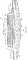
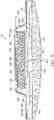
- FIG. 4A depicts an illustrative embodiment of the dressing assembly 112 in a relaxed state positioned at the tissue site 102 prior to operation or application of reduced pressure.
- FIG. 4B depicts the dressing assembly 112 in a contracted state during operation or application of reduced pressure to the sealed space 120.
- the dressing assembly 112 of FIGS. 4A-4B is shown with the comfort layer 160.
- any embodiments within the scope of this disclosure, including those that do not use the comfort layer 160 may be suitable, applicable, substituted, or operable in an analogous manner.
- the dressing bolster 114 may contract, bend, or curl about a longitudinal axis of the dressing bolster 114 into a convex shape on the first side 128 of the dressing bolster 114 and a concave shape on the second side 152 of the dressing bolster 114 facing the tissue site 102.
- the longitudinal axis of the dressing bolster 114 may extend into the page in the view shown in FIGS. 4A-4B and be centered along the length of the dressing bolster 114 over the incision 104, for example.
- FIG. 4B does not illustrate the concave shape of the second side 152 of the dressing bolster 114 during operation.
- contraction force vectors (A, B) in FIG. 4B illustrate a direction of a force that may be applied by the dressing assembly 112 during operation.
- contraction force vector (A) illustrates the direction of the force that may be applied to the tissue site 102 by the second side 152 of the dressing bolster 114.
- Contraction force vector (B) illustrates the direction of the force that may be applied to the tissue site 102 by the sealing member 116, for example, by the periphery 122 of the sealing member 116 coupled on the epidermis 106 around the tissue site 102.
- the contraction of the dressing bolster 114 may cause at least one of the edges 126 of the dressing bolster 114 to move toward or closer to one another.
- the contraction of the dressing bolster 114 may permit the dressing assembly 112 to impart an inward force or an apposition force to the tissue site 102 that may move the first portion 180 of the tissue site 102 toward the second portion 182 of the tissue site 102 as shown by the contraction force vectors (A, B).
- the movement of the first portion 180 toward or closer to the second portion 182 may provide closure of the incision 104 at the tissue site 102.
- testing results for the dressing assembly 112 may provide a 40% to a 100% improvement in closure of an incision, such as the incision 104, compared to a conventional dressing used to establish a baseline comparison.
- an incision such as the incision 104
- a conventional dressing used to establish a baseline comparison.
- a 6 millimeter wide, 36 centimeter long simulated incision was formed in a 3 millimeter thick gel sheet having a thin polymeric film surface.
- the gel sheet selected for the testing is available under the tradename DERMASOL DS-302.
- FIG. 5A references the measurement locations along the incision 104 relative to the dressing assembly 112 as locations -4, -3, -2, - 1, 0, 1, 2, 3, and 4.
- FIG. 5B The measurement data for the dressing assembly 112 and the baseline dressing are tabulated and compared in FIG. 5B at the stated times and locations.
- SE Mean and Standard Error
- FIG. 5B illustrates a Mean Ratio ranging from 1.4 to 2.0, corresponding to a 40% to 100% percent improvement in the closure or decrease of the incision width using the dressing assembly 112.
Claims (15)
- Ensemble de pansement (112) configuré pour traiter un site tissulaire (102), comprenant :un collecteur (114) configuré pour distribuer une pression réduite au site tissulaire (102, le collecteur (114) comprenant un premier côté (128), un second côté (152) opposé au premier côté (128), et une épaisseur (154) entre le premier côté (128) et le second côté (152), le second côté (152) configuré pour faire face au site tissulaire (102) ;une première zone de contraction (170) s'étendant à partir du premier côté (128) dans l'épaisseur (154) du collecteur (114) et vers le second côté (152), la première zone de contraction (170) configurée pour se contracter d'une première quantité ; etune seconde zone de contraction (172) s'étendant à partir de la première zone de contraction (170) dans l'épaisseur (154) du collecteur (114) et vers le second côté (152), la seconde zone de contraction (172) configurée pour se contracter d'une seconde quantité qui est supérieure à la première quantité lorsque la pression réduite est appliquée au collecteur (114),dans lequel la première zone de contraction (170) a une rigidité supérieure à la seconde zone de contraction (172), etle second côté (152) du collecteur (114) est configuré pour constituer une forme concave configurée pour faire face au site tissulaire (102) lorsque la première zone de contraction (170) se contracte de la première quantité et la seconde zone de contraction (172) se contracte de la seconde quantité.
- Ensemble de pansement selon la revendication 1, comprenant en outre une couche d'interface (160) configurée pour être positionnée entre le second côté (152) du collecteur (114) et le site tissulaire (102).
- Ensemble de pansement selon la revendication 1, comprenant en outre un élément de fermeture hermétique (116) configuré pour couvrir le collecteur (114) et pour créer un espace hermétiquement fermé (120) par rapport au site tissulaire (102), dans lequel l'élément de fermeture hermétique comprend éventuellement un film imperméable aux liquides.
- Ensemble de pansement selon la revendication 1, dans lequel au moins une partie de la seconde zone de contraction (172) est positionnée au niveau du second côté (152) du collecteur (114).
- Ensemble de pansement selon la revendication 1, dans lequel la seconde zone de contraction (172) est configurée pour être positionnée entre la première zone de contraction (170) et le site tissulaire (102).
- Ensemble de pansement selon la revendication 1, dans lequel la première zone de contraction (170) et la seconde zone de contraction (172) comprennent chacune une partie du collecteur (114) configurée pour avoir des propriétés mécaniques différentes.
- Ensemble de pansement selon la revendication 1, dans lequel la première zone de contraction (170) est configurée pour se contracter de la première quantité et la seconde zone de contraction (172) est configurée pour se contracter de la seconde quantité lorsque la première zone de contraction (170) et la seconde zone de contraction (172) sont exposées à des quantités égales de la pression réduite.
- Ensemble de pansement selon la revendication 1, dans lequel la première zone de contraction (170) et la seconde zone de contraction (172) s'étendent à travers une largeur du collecteur (114).
- Ensemble de pansement selon la revendication 1, dans lequel la première zone de contraction (170) est configurée pour se contracter de la première quantité et la seconde zone de contraction (172) est configurée pour se contracter de la seconde quantité en réponse à une force mécanique ou à une charge électrique.
- Ensemble de pansement selon la revendication 1, dans lequel la première zone de contraction (170) comprend une première couche du collecteur (114) et la seconde zone de contraction (172) comprend une seconde couche du collecteur (114).
- Ensemble de pansement selon la revendication 1, dans lequel la seconde zone de contraction (172) s'étend dans l'épaisseur du collecteur (114) jusqu'à une profondeur supérieure à une profondeur de la première zone de contraction (170).
- Ensemble de pansement selon la revendication 1, dans lequel la première zone de contraction (170) et la seconde zone de contraction (172) comprennent une mousse, et dans lequel une porosité de la mousse dans la seconde zone de contraction est supérieure à une porosité de la mousse dans la première zone de contraction.
- Ensemble de pansement selon la revendication 1, dans lequel la première zone de contraction (170) est configurée pour se contracter de la première quantité et la seconde zone de contraction (172) est configurée pour se contracter de la seconde quantité dans une direction essentiellement perpendiculaire à l'épaisseur du collecteur (114).
- Ensemble de pansement selon la revendication 1, dans lequel la première zone de contraction (170) est configurée pour se contracter de la première quantité et la seconde zone de contraction (172) est configurée pour se contracter de la seconde quantité dans une direction latérale par rapport au site tissulaire (102).
- Système de traitement (100) pour traiter un site tissulaire (102) comprenant l'ensemble de pansement (112) selon la revendication 1, le système comprenant en outre :une couche d'interface (160) configurée pour être positionnée entre le second côté (152) du collecteur (114) et le site tissulaire (102) ;un élément de fermeture hermétique (116) configuré pour couvrir le collecteur (114) et pour créer un espace hermétiquement fermé (120) par rapport au site tissulaire (102) ; etune source de pression réduite (142) configurée pour être couplée en communication fluidique avec l'espace hermétiquement fermé (120) et pour fournir la pression réduite à l'espace hermétiquement fermé (120), dans lequel la pression réduite génère une force de compression sur le collecteur (114).
Applications Claiming Priority (2)
| Application Number | Priority Date | Filing Date | Title |
|---|---|---|---|
| US201762458916P | 2017-02-14 | 2017-02-14 | |
| PCT/US2018/018054 WO2018152127A1 (fr) | 2017-02-14 | 2018-02-13 | Pansement à zones de contraction variable |
Publications (2)
| Publication Number | Publication Date |
|---|---|
| EP3582731A1 EP3582731A1 (fr) | 2019-12-25 |
| EP3582731B1 true EP3582731B1 (fr) | 2022-08-17 |
Family
ID=61283377
Family Applications (1)
| Application Number | Title | Priority Date | Filing Date |
|---|---|---|---|
| EP18707552.8A Active EP3582731B1 (fr) | 2017-02-14 | 2018-02-13 | Pansement à zones de contraction variable |
Country Status (6)
| Country | Link |
|---|---|
| US (2) | US11291587B2 (fr) |
| EP (1) | EP3582731B1 (fr) |
| JP (1) | JP7376357B2 (fr) |
| CN (1) | CN110290770B (fr) |
| CA (1) | CA3049463A1 (fr) |
| WO (1) | WO2018152127A1 (fr) |
Cited By (1)
| Publication number | Priority date | Publication date | Assignee | Title |
|---|---|---|---|---|
| US11878104B2 (en) | 2020-02-20 | 2024-01-23 | Convatec Limited | Wound dressing and a wound therapy apparatus |
Families Citing this family (8)
| Publication number | Priority date | Publication date | Assignee | Title |
|---|---|---|---|---|
| US11740241B2 (en) | 2016-03-30 | 2023-08-29 | Synovo Gmbh | Construct including an anchor, an enzyme recognition site and an indicator region for detecting microbial infection in wounds |
| CA3049463A1 (fr) * | 2017-02-14 | 2018-08-23 | Kci Licensing, Inc. | Pansement a zones de contraction variable |
| WO2019199849A1 (fr) * | 2018-04-13 | 2019-10-17 | Kci Licensing, Inc. | Coussin de pansement avec indicateur de pression de zone |
| JP2021534875A (ja) * | 2018-09-04 | 2021-12-16 | ケーシーアイ ライセンシング インコーポレイテッド | 創傷療法装置及びキット |
| JP2022527313A (ja) | 2019-03-29 | 2022-06-01 | ケーシーアイ ライセンシング インコーポレイテッド | 領域安定化を伴う陰圧治療 |
| CN113660963A (zh) | 2019-03-29 | 2021-11-16 | 凯希特许有限公司 | 具有区域稳定性的负压治疗 |
| EP4051201A1 (fr) * | 2019-11-01 | 2022-09-07 | KCI Licensing, Inc. | Système de traitement de thérapie par décompression |
| USD1014764S1 (en) * | 2021-11-16 | 2024-02-13 | Raymond Lovell Francis | Skin-attachable block set that provides no-touch protection for skin insults |
Family Cites Families (147)
| Publication number | Priority date | Publication date | Assignee | Title |
|---|---|---|---|---|
| US1355846A (en) | 1920-02-06 | 1920-10-19 | David A Rannells | Medical appliance |
| US2547758A (en) | 1949-01-05 | 1951-04-03 | Wilmer B Keeling | Instrument for treating the male urethra |
| US2632443A (en) | 1949-04-18 | 1953-03-24 | Eleanor P Lesher | Surgical dressing |
| GB692578A (en) | 1949-09-13 | 1953-06-10 | Minnesota Mining & Mfg | Improvements in or relating to drape sheets for surgical use |
| US2682873A (en) | 1952-07-30 | 1954-07-06 | Johnson & Johnson | General purpose protective dressing |
| NL189176B (nl) | 1956-07-13 | 1900-01-01 | Hisamitsu Pharmaceutical Co | Pleister op basis van een synthetische rubber. |
| US2969057A (en) | 1957-11-04 | 1961-01-24 | Brady Co W H | Nematodic swab |
| US3066672A (en) | 1960-09-27 | 1962-12-04 | Jr William H Crosby | Method and apparatus for serial sampling of intestinal juice |
| US3367332A (en) | 1965-08-27 | 1968-02-06 | Gen Electric | Product and process for establishing a sterile area of skin |
| US3520300A (en) | 1967-03-15 | 1970-07-14 | Amp Inc | Surgical sponge and suction device |
| US3568675A (en) | 1968-08-30 | 1971-03-09 | Clyde B Harvey | Fistula and penetrating wound dressing |
| US3682180A (en) | 1970-06-08 | 1972-08-08 | Coilform Co Inc | Drain clip for surgical drain |
| BE789293Q (fr) | 1970-12-07 | 1973-01-15 | Parke Davis & Co | Pansement medico-chirugical pour brulures et lesions analogues |
| US3826254A (en) | 1973-02-26 | 1974-07-30 | Verco Ind | Needle or catheter retaining appliance |
| DE2527706A1 (de) | 1975-06-21 | 1976-12-30 | Hanfried Dr Med Weigand | Einrichtung zum einleiten von kontrastmittel in einen kuenstlichen darmausgang |
| DE2640413C3 (de) | 1976-09-08 | 1980-03-27 | Richard Wolf Gmbh, 7134 Knittlingen | Katheter-Überwachungsgerät |
| NL7710909A (nl) | 1976-10-08 | 1978-04-11 | Smith & Nephew | Samengestelde hechtstrook. |
| GB1562244A (en) | 1976-11-11 | 1980-03-05 | Lock P M | Wound dressing materials |
| US4080970A (en) | 1976-11-17 | 1978-03-28 | Miller Thomas J | Post-operative combination dressing and internal drain tube with external shield and tube connector |
| US4139004A (en) | 1977-02-17 | 1979-02-13 | Gonzalez Jr Harry | Bandage apparatus for treating burns |
| US4184510A (en) | 1977-03-15 | 1980-01-22 | Fibra-Sonics, Inc. | Valued device for controlling vacuum in surgery |
| US4165748A (en) | 1977-11-07 | 1979-08-28 | Johnson Melissa C | Catheter tube holder |
| US4256109A (en) | 1978-07-10 | 1981-03-17 | Nichols Robert L | Shut off valve for medical suction apparatus |
| SE414994B (sv) | 1978-11-28 | 1980-09-01 | Landstingens Inkopscentral | Venkateterforband |
| BR7908937A (pt) | 1978-12-06 | 1981-06-30 | Svedman Paul | Dispositivo para tratamento de tecidos,por exemplo,pele |
| US4266545A (en) | 1979-04-06 | 1981-05-12 | Moss James P | Portable suction device for collecting fluids from a closed wound |
| US4284079A (en) | 1979-06-28 | 1981-08-18 | Adair Edwin Lloyd | Method for applying a male incontinence device |
| US4261363A (en) | 1979-11-09 | 1981-04-14 | C. R. Bard, Inc. | Retention clips for body fluid drains |
| US4569348A (en) | 1980-02-22 | 1986-02-11 | Velcro Usa Inc. | Catheter tube holder strap |
| ATE14835T1 (de) | 1980-03-11 | 1985-08-15 | Schmid Eduard | Hauttransplantations-druckverband. |
| US4297995A (en) | 1980-06-03 | 1981-11-03 | Key Pharmaceuticals, Inc. | Bandage containing attachment post |
| US4333468A (en) | 1980-08-18 | 1982-06-08 | Geist Robert W | Mesentery tube holder apparatus |
| US4465485A (en) | 1981-03-06 | 1984-08-14 | Becton, Dickinson And Company | Suction canister with unitary shut-off valve and filter features |
| US4392853A (en) | 1981-03-16 | 1983-07-12 | Rudolph Muto | Sterile assembly for protecting and fastening an indwelling device |
| US4373519A (en) | 1981-06-26 | 1983-02-15 | Minnesota Mining And Manufacturing Company | Composite wound dressing |
| US4392858A (en) | 1981-07-16 | 1983-07-12 | Sherwood Medical Company | Wound drainage device |
| US4419097A (en) | 1981-07-31 | 1983-12-06 | Rexar Industries, Inc. | Attachment for catheter tube |
| AU550575B2 (en) | 1981-08-07 | 1986-03-27 | Richard Christian Wright | Wound drainage device |
| SE429197B (sv) | 1981-10-14 | 1983-08-22 | Frese Nielsen | Anordning for behandling av sar |
| DE3146266A1 (de) | 1981-11-21 | 1983-06-01 | B. Braun Melsungen Ag, 3508 Melsungen | Kombinierte vorrichtung fuer eine medizinische saugdrainage |
| US4551139A (en) | 1982-02-08 | 1985-11-05 | Marion Laboratories, Inc. | Method and apparatus for burn wound treatment |
| US4475909A (en) | 1982-05-06 | 1984-10-09 | Eisenberg Melvin I | Male urinary device and method for applying the device |
| EP0100148B1 (fr) | 1982-07-06 | 1986-01-08 | Dow Corning Limited | Pansement médico-chirurgical et son procédé de production |
| NZ206837A (en) | 1983-01-27 | 1986-08-08 | Johnson & Johnson Prod Inc | Thin film adhesive dressing:backing material in three sections |
| US4548202A (en) | 1983-06-20 | 1985-10-22 | Ethicon, Inc. | Mesh tissue fasteners |
| US4540412A (en) | 1983-07-14 | 1985-09-10 | The Kendall Company | Device for moist heat therapy |
| US4543100A (en) | 1983-11-01 | 1985-09-24 | Brodsky Stuart A | Catheter and drain tube retainer |
| US4525374A (en) | 1984-02-27 | 1985-06-25 | Manresa, Inc. | Treating hydrophobic filters to render them hydrophilic |
| GB2157958A (en) | 1984-05-03 | 1985-11-06 | Ernest Edward Austen Bedding | Ball game net support |
| US4897081A (en) | 1984-05-25 | 1990-01-30 | Thermedics Inc. | Percutaneous access device |
| US5215522A (en) | 1984-07-23 | 1993-06-01 | Ballard Medical Products | Single use medical aspirating device and method |
| GB8419745D0 (en) | 1984-08-02 | 1984-09-05 | Smith & Nephew Ass | Wound dressing |
| US4872450A (en) | 1984-08-17 | 1989-10-10 | Austad Eric D | Wound dressing and method of forming same |
| US4655754A (en) | 1984-11-09 | 1987-04-07 | Stryker Corporation | Vacuum wound drainage system and lipids baffle therefor |
| US4826494A (en) | 1984-11-09 | 1989-05-02 | Stryker Corporation | Vacuum wound drainage system |
| US4605399A (en) | 1984-12-04 | 1986-08-12 | Complex, Inc. | Transdermal infusion device |
| US5037397A (en) | 1985-05-03 | 1991-08-06 | Medical Distributors, Inc. | Universal clamp |
| US4640688A (en) | 1985-08-23 | 1987-02-03 | Mentor Corporation | Urine collection catheter |
| US4710165A (en) | 1985-09-16 | 1987-12-01 | Mcneil Charles B | Wearable, variable rate suction/collection device |
| US4758220A (en) | 1985-09-26 | 1988-07-19 | Alcon Laboratories, Inc. | Surgical cassette proximity sensing and latching apparatus |
| US4733659A (en) | 1986-01-17 | 1988-03-29 | Seton Company | Foam bandage |
| EP0256060A1 (fr) | 1986-01-31 | 1988-02-24 | OSMOND, Roger L. W. | Systeme de succion pour drainage de blessures et drainage gastro-intestinal |
| US4838883A (en) | 1986-03-07 | 1989-06-13 | Nissho Corporation | Urine-collecting device |
| JPS62281965A (ja) | 1986-05-29 | 1987-12-07 | テルモ株式会社 | カテ−テルおよびカテ−テル用固定部材 |
| GB8621884D0 (en) | 1986-09-11 | 1986-10-15 | Bard Ltd | Catheter applicator |
| GB2195255B (en) | 1986-09-30 | 1991-05-01 | Vacutec Uk Limited | Apparatus for vacuum treatment of an epidermal surface |
| US4743232A (en) | 1986-10-06 | 1988-05-10 | The Clinipad Corporation | Package assembly for plastic film bandage |
| DE3634569A1 (de) | 1986-10-10 | 1988-04-21 | Sachse Hans E | Kondomkatheter, ein harnroehrenkatheter zur verhinderung von aufsteigenden infektionen |
| JPS63135179A (ja) | 1986-11-26 | 1988-06-07 | 立花 俊郎 | 薬物の経皮投与具 |
| GB8628564D0 (en) | 1986-11-28 | 1987-01-07 | Smiths Industries Plc | Anti-foaming agent suction apparatus |
| GB8706116D0 (en) | 1987-03-14 | 1987-04-15 | Smith & Nephew Ass | Adhesive dressings |
| US4787888A (en) | 1987-06-01 | 1988-11-29 | University Of Connecticut | Disposable piezoelectric polymer bandage for percutaneous delivery of drugs and method for such percutaneous delivery (a) |
| US4863449A (en) | 1987-07-06 | 1989-09-05 | Hollister Incorporated | Adhesive-lined elastic condom cathether |
| US5176663A (en) | 1987-12-02 | 1993-01-05 | Pal Svedman | Dressing having pad with compressibility limiting elements |
| US4906240A (en) | 1988-02-01 | 1990-03-06 | Matrix Medica, Inc. | Adhesive-faced porous absorbent sheet and method of making same |
| US4985019A (en) | 1988-03-11 | 1991-01-15 | Michelson Gary K | X-ray marker |
| GB8812803D0 (en) | 1988-05-28 | 1988-06-29 | Smiths Industries Plc | Medico-surgical containers |
| US4919654A (en) | 1988-08-03 | 1990-04-24 | Kalt Medical Corporation | IV clamp with membrane |
| US5000741A (en) | 1988-08-22 | 1991-03-19 | Kalt Medical Corporation | Transparent tracheostomy tube dressing |
| DE69017479T2 (de) | 1989-01-16 | 1995-07-13 | Roussel Uclaf | Azabicycloheptenderivate und ihre Salze, Verfahren zu ihrer Herstellung, ihre Verwendung als Arzneimittel und diese enthaltende Zubereitungen. |
| GB8906100D0 (en) | 1989-03-16 | 1989-04-26 | Smith & Nephew | Laminates |
| US5261893A (en) | 1989-04-03 | 1993-11-16 | Zamierowski David S | Fastening system and method |
| US5527293A (en) | 1989-04-03 | 1996-06-18 | Kinetic Concepts, Inc. | Fastening system and method |
| US4969880A (en) | 1989-04-03 | 1990-11-13 | Zamierowski David S | Wound dressing and treatment method |
| US5100396A (en) | 1989-04-03 | 1992-03-31 | Zamierowski David S | Fluidic connection system and method |
| US5358494A (en) | 1989-07-11 | 1994-10-25 | Svedman Paul | Irrigation dressing |
| JP2719671B2 (ja) | 1989-07-11 | 1998-02-25 | 日本ゼオン株式会社 | 創傷被覆材 |
| US5232453A (en) | 1989-07-14 | 1993-08-03 | E. R. Squibb & Sons, Inc. | Catheter holder |
| GB2235877A (en) | 1989-09-18 | 1991-03-20 | Antonio Talluri | Closed wound suction apparatus |
| US5134994A (en) | 1990-02-12 | 1992-08-04 | Say Sam L | Field aspirator in a soft pack with externally mounted container |
| US5092858A (en) | 1990-03-20 | 1992-03-03 | Becton, Dickinson And Company | Liquid gelling agent distributor device |
| US5149331A (en) | 1991-05-03 | 1992-09-22 | Ariel Ferdman | Method and device for wound closure |
| US5278100A (en) | 1991-11-08 | 1994-01-11 | Micron Technology, Inc. | Chemical vapor deposition technique for depositing titanium silicide on semiconductor wafers |
| US5636643A (en) | 1991-11-14 | 1997-06-10 | Wake Forest University | Wound treatment employing reduced pressure |
| US5645081A (en) | 1991-11-14 | 1997-07-08 | Wake Forest University | Method of treating tissue damage and apparatus for same |
| US5279550A (en) | 1991-12-19 | 1994-01-18 | Gish Biomedical, Inc. | Orthopedic autotransfusion system |
| US5167613A (en) | 1992-03-23 | 1992-12-01 | The Kendall Company | Composite vented wound dressing |
| FR2690617B1 (fr) | 1992-04-29 | 1994-06-24 | Cbh Textile | Pansement adhesif transparent. |
| DE4306478A1 (de) | 1993-03-02 | 1994-09-08 | Wolfgang Dr Wagner | Drainagevorrichtung, insbesondere Pleuradrainagevorrichtung, und Drainageverfahren |
| US6241747B1 (en) | 1993-05-03 | 2001-06-05 | Quill Medical, Inc. | Barbed Bodily tissue connector |
| US5342376A (en) | 1993-05-03 | 1994-08-30 | Dermagraphics, Inc. | Inserting device for a barbed tissue connector |
| US5344415A (en) | 1993-06-15 | 1994-09-06 | Deroyal Industries, Inc. | Sterile system for dressing vascular access site |
| US5437651A (en) | 1993-09-01 | 1995-08-01 | Research Medical, Inc. | Medical suction apparatus |
| US5549584A (en) | 1994-02-14 | 1996-08-27 | The Kendall Company | Apparatus for removing fluid from a wound |
| US5607388A (en) | 1994-06-16 | 1997-03-04 | Hercules Incorporated | Multi-purpose wound dressing |
| US5556375A (en) | 1994-06-16 | 1996-09-17 | Hercules Incorporated | Wound dressing having a fenestrated base layer |
| US5664270A (en) | 1994-07-19 | 1997-09-09 | Kinetic Concepts, Inc. | Patient interface system |
| AU698477B2 (en) | 1994-08-22 | 1998-10-29 | Kci Licensing, Inc. | Wound drainage equipment |
| DE29504378U1 (de) | 1995-03-15 | 1995-09-14 | Mtg Medizinisch Tech Geraeteba | Elektronisch geregelte Niedervakuumpumpe für die Thorax- und Wunddrainage |
| GB9523253D0 (en) | 1995-11-14 | 1996-01-17 | Mediscus Prod Ltd | Portable wound treatment apparatus |
| US6135116A (en) | 1997-07-28 | 2000-10-24 | Kci Licensing, Inc. | Therapeutic method for treating ulcers |
| GB9719520D0 (en) | 1997-09-12 | 1997-11-19 | Kci Medical Ltd | Surgical drape and suction heads for wound treatment |
| AU755496B2 (en) | 1997-09-12 | 2002-12-12 | Kci Licensing, Inc. | Surgical drape and suction head for wound treatment |
| US6071267A (en) | 1998-02-06 | 2000-06-06 | Kinetic Concepts, Inc. | Medical patient fluid management interface system and method |
| US6488643B1 (en) | 1998-10-08 | 2002-12-03 | Kci Licensing, Inc. | Wound healing foot wrap |
| US6287316B1 (en) | 1999-03-26 | 2001-09-11 | Ethicon, Inc. | Knitted surgical mesh |
| US6856821B2 (en) | 2000-05-26 | 2005-02-15 | Kci Licensing, Inc. | System for combined transcutaneous blood gas monitoring and vacuum assisted wound closure |
| US7799004B2 (en) | 2001-03-05 | 2010-09-21 | Kci Licensing, Inc. | Negative pressure wound treatment apparatus and infection identification system and method |
| US6991643B2 (en) | 2000-12-20 | 2006-01-31 | Usgi Medical Inc. | Multi-barbed device for retaining tissue in apposition and methods of use |
| ATE266443T1 (de) | 2000-02-24 | 2004-05-15 | Venetec Int Inc | Universelles katheterbefestigungssystem |
| US6540705B2 (en) | 2001-02-22 | 2003-04-01 | Core Products International, Inc. | Ankle brace providing upper and lower ankle adjustment |
| US7846141B2 (en) | 2002-09-03 | 2010-12-07 | Bluesky Medical Group Incorporated | Reduced pressure treatment system |
| US7625362B2 (en) * | 2003-09-16 | 2009-12-01 | Boehringer Technologies, L.P. | Apparatus and method for suction-assisted wound healing |
| GB0224986D0 (en) | 2002-10-28 | 2002-12-04 | Smith & Nephew | Apparatus |
| GB0325120D0 (en) | 2003-10-28 | 2003-12-03 | Smith & Nephew | Apparatus with actives |
| GB0325126D0 (en) | 2003-10-28 | 2003-12-03 | Smith & Nephew | Apparatus with heat |
| US7909805B2 (en) | 2004-04-05 | 2011-03-22 | Bluesky Medical Group Incorporated | Flexible reduced pressure treatment appliance |
| US8529548B2 (en) | 2004-04-27 | 2013-09-10 | Smith & Nephew Plc | Wound treatment apparatus and method |
| CN101257875A (zh) * | 2005-09-06 | 2008-09-03 | 泰科保健集团有限合伙公司 | 具有微型泵的独立伤口敷料 |
| CN101257938A (zh) * | 2005-09-07 | 2008-09-03 | 泰科保健集团有限合伙公司 | 具有真空储存器的伤口敷料 |
| AU2013270493B2 (en) * | 2007-01-25 | 2015-09-10 | Solventum Intellectual Properties Company | Biocompatible wound dressing |
| AU2014277788B2 (en) * | 2008-03-05 | 2016-11-03 | Solventum Intellectual Properties Company | Dressing and method for applying reduced pressure to and collecting and storing fluid from a tissue site |
| US8298200B2 (en) * | 2009-06-01 | 2012-10-30 | Tyco Healthcare Group Lp | System for providing continual drainage in negative pressure wound therapy |
| US8021347B2 (en) | 2008-07-21 | 2011-09-20 | Tyco Healthcare Group Lp | Thin film wound dressing |
| US8007481B2 (en) | 2008-07-17 | 2011-08-30 | Tyco Healthcare Group Lp | Subatmospheric pressure mechanism for wound therapy system |
| CA2725569C (fr) * | 2008-05-30 | 2014-11-25 | Kci Licensing, Inc. | Chapeaux et systemes de fermeture a enroulement lineaire et a pression reduite |
| US9572719B2 (en) | 2008-05-30 | 2017-02-21 | Kci Licensing, Inc. | Reduced-pressure surgical wound treatment systems and methods |
| US8216198B2 (en) | 2009-01-09 | 2012-07-10 | Tyco Healthcare Group Lp | Canister for receiving wound exudate in a negative pressure therapy system |
| US8251979B2 (en) | 2009-05-11 | 2012-08-28 | Tyco Healthcare Group Lp | Orientation independent canister for a negative pressure wound therapy device |
| US20100191196A1 (en) * | 2009-01-26 | 2010-07-29 | Heagle David G | Fibrous Wound Filler Material for Negative Pressure Wound Therapy |
| ES1070675Y (es) * | 2009-05-20 | 2010-01-14 | Canada Juan Marquez | Aposito de vacio mejorado aplicable como tratamiento de compresion postoperatoria |
| US8529526B2 (en) * | 2009-10-20 | 2013-09-10 | Kci Licensing, Inc. | Dressing reduced-pressure indicators, systems, and methods |
| WO2013007973A2 (fr) | 2011-07-14 | 2013-01-17 | Smith & Nephew Plc | Pansement et méthode de traitement |
| US9107990B2 (en) * | 2011-02-14 | 2015-08-18 | Kci Licensing, Inc. | Reduced-pressure dressings, systems, and methods for use with linear wounds |
| WO2013074829A1 (fr) * | 2011-11-18 | 2013-05-23 | Kci Licensing, Inc. | Systèmes et procédés de traitement de tissus comprenant un substrat poreux doté d'une région comprimée et d'une région expansée |
| CN104487033B (zh) | 2012-07-30 | 2018-06-15 | 凯希特许有限公司 | 用于治疗组织部位的减压吸收性敷件、系统以及制造该敷件的方法 |
| CA3049463A1 (fr) * | 2017-02-14 | 2018-08-23 | Kci Licensing, Inc. | Pansement a zones de contraction variable |
-
2018
- 2018-02-13 CA CA3049463A patent/CA3049463A1/fr active Pending
- 2018-02-13 EP EP18707552.8A patent/EP3582731B1/fr active Active
- 2018-02-13 JP JP2019543383A patent/JP7376357B2/ja active Active
- 2018-02-13 WO PCT/US2018/018054 patent/WO2018152127A1/fr unknown
- 2018-02-13 CN CN201880011363.1A patent/CN110290770B/zh active Active
- 2018-02-13 US US15/895,851 patent/US11291587B2/en active Active
-
2021
- 2021-10-13 US US17/500,136 patent/US20220031520A1/en active Pending
Cited By (1)
| Publication number | Priority date | Publication date | Assignee | Title |
|---|---|---|---|---|
| US11878104B2 (en) | 2020-02-20 | 2024-01-23 | Convatec Limited | Wound dressing and a wound therapy apparatus |
Also Published As
| Publication number | Publication date |
|---|---|
| JP7376357B2 (ja) | 2023-11-08 |
| CN110290770A (zh) | 2019-09-27 |
| US20180228653A1 (en) | 2018-08-16 |
| CN110290770B (zh) | 2022-03-29 |
| WO2018152127A1 (fr) | 2018-08-23 |
| EP3582731A1 (fr) | 2019-12-25 |
| US11291587B2 (en) | 2022-04-05 |
| JP2020506015A (ja) | 2020-02-27 |
| US20220031520A1 (en) | 2022-02-03 |
| CA3049463A1 (fr) | 2018-08-23 |
Similar Documents
| Publication | Publication Date | Title |
|---|---|---|
| US11950984B2 (en) | Dressing with increased apposition force | |
| EP3582731B1 (fr) | Pansement à zones de contraction variable | |
| US11786413B2 (en) | Medical drapes and methods for reducing trauma on removal | |
| EP3038667B1 (fr) | Interface de pansement avec caractéristique de contrôle de l'humidité et fonction d'étanchéité | |
| EP2968012B1 (fr) | Pansement absorbant avec champ hybride | |
| AU2017266861B2 (en) | Replaceable dressing and method for viewing a tissue site | |
| EP4007551B1 (fr) | Pansement ayant une caractéristique d'épithélialisation et de réduction de cicatrice |
Legal Events
| Date | Code | Title | Description |
|---|---|---|---|
| STAA | Information on the status of an ep patent application or granted ep patent |
Free format text: STATUS: UNKNOWN |
|
| STAA | Information on the status of an ep patent application or granted ep patent |
Free format text: STATUS: THE INTERNATIONAL PUBLICATION HAS BEEN MADE |
|
| PUAI | Public reference made under article 153(3) epc to a published international application that has entered the european phase |
Free format text: ORIGINAL CODE: 0009012 |
|
| STAA | Information on the status of an ep patent application or granted ep patent |
Free format text: STATUS: REQUEST FOR EXAMINATION WAS MADE |
|
| 17P | Request for examination filed |
Effective date: 20190916 |
|
| AK | Designated contracting states |
Kind code of ref document: A1 Designated state(s): AL AT BE BG CH CY CZ DE DK EE ES FI FR GB GR HR HU IE IS IT LI LT LU LV MC MK MT NL NO PL PT RO RS SE SI SK SM TR |
|
| AX | Request for extension of the european patent |
Extension state: BA ME |
|
| DAV | Request for validation of the european patent (deleted) | ||
| DAX | Request for extension of the european patent (deleted) | ||
| RAP1 | Party data changed (applicant data changed or rights of an application transferred) |
Owner name: 3M INNOVATIVE PROPERTIES COMPANY |
|
| GRAP | Despatch of communication of intention to grant a patent |
Free format text: ORIGINAL CODE: EPIDOSNIGR1 |
|
| STAA | Information on the status of an ep patent application or granted ep patent |
Free format text: STATUS: GRANT OF PATENT IS INTENDED |
|
| INTG | Intention to grant announced |
Effective date: 20220518 |
|
| GRAS | Grant fee paid |
Free format text: ORIGINAL CODE: EPIDOSNIGR3 |
|
| GRAA | (expected) grant |
Free format text: ORIGINAL CODE: 0009210 |
|
| STAA | Information on the status of an ep patent application or granted ep patent |
Free format text: STATUS: THE PATENT HAS BEEN GRANTED |
|
| AK | Designated contracting states |
Kind code of ref document: B1 Designated state(s): AL AT BE BG CH CY CZ DE DK EE ES FI FR GB GR HR HU IE IS IT LI LT LU LV MC MK MT NL NO PL PT RO RS SE SI SK SM TR |
|
| REG | Reference to a national code |
Ref country code: CH Ref legal event code: EP |
|
| REG | Reference to a national code |
Ref country code: DE Ref legal event code: R096 Ref document number: 602018039361 Country of ref document: DE |
|
| REG | Reference to a national code |
Ref country code: IE Ref legal event code: FG4D |
|
| REG | Reference to a national code |
Ref country code: AT Ref legal event code: REF Ref document number: 1511691 Country of ref document: AT Kind code of ref document: T Effective date: 20220915 |
|
| REG | Reference to a national code |
Ref country code: NL Ref legal event code: MP Effective date: 20220817 |
|
| REG | Reference to a national code |
Ref country code: LT Ref legal event code: MG9D |
|
| PG25 | Lapsed in a contracting state [announced via postgrant information from national office to epo] |
Ref country code: SE Free format text: LAPSE BECAUSE OF FAILURE TO SUBMIT A TRANSLATION OF THE DESCRIPTION OR TO PAY THE FEE WITHIN THE PRESCRIBED TIME-LIMIT Effective date: 20220817 Ref country code: RS Free format text: LAPSE BECAUSE OF FAILURE TO SUBMIT A TRANSLATION OF THE DESCRIPTION OR TO PAY THE FEE WITHIN THE PRESCRIBED TIME-LIMIT Effective date: 20220817 Ref country code: PT Free format text: LAPSE BECAUSE OF FAILURE TO SUBMIT A TRANSLATION OF THE DESCRIPTION OR TO PAY THE FEE WITHIN THE PRESCRIBED TIME-LIMIT Effective date: 20221219 Ref country code: NO Free format text: LAPSE BECAUSE OF FAILURE TO SUBMIT A TRANSLATION OF THE DESCRIPTION OR TO PAY THE FEE WITHIN THE PRESCRIBED TIME-LIMIT Effective date: 20221117 Ref country code: NL Free format text: LAPSE BECAUSE OF FAILURE TO SUBMIT A TRANSLATION OF THE DESCRIPTION OR TO PAY THE FEE WITHIN THE PRESCRIBED TIME-LIMIT Effective date: 20220817 Ref country code: LV Free format text: LAPSE BECAUSE OF FAILURE TO SUBMIT A TRANSLATION OF THE DESCRIPTION OR TO PAY THE FEE WITHIN THE PRESCRIBED TIME-LIMIT Effective date: 20220817 Ref country code: LT Free format text: LAPSE BECAUSE OF FAILURE TO SUBMIT A TRANSLATION OF THE DESCRIPTION OR TO PAY THE FEE WITHIN THE PRESCRIBED TIME-LIMIT Effective date: 20220817 Ref country code: FI Free format text: LAPSE BECAUSE OF FAILURE TO SUBMIT A TRANSLATION OF THE DESCRIPTION OR TO PAY THE FEE WITHIN THE PRESCRIBED TIME-LIMIT Effective date: 20220817 |
|
| REG | Reference to a national code |
Ref country code: AT Ref legal event code: MK05 Ref document number: 1511691 Country of ref document: AT Kind code of ref document: T Effective date: 20220817 |
|
| PG25 | Lapsed in a contracting state [announced via postgrant information from national office to epo] |
Ref country code: PL Free format text: LAPSE BECAUSE OF FAILURE TO SUBMIT A TRANSLATION OF THE DESCRIPTION OR TO PAY THE FEE WITHIN THE PRESCRIBED TIME-LIMIT Effective date: 20220817 Ref country code: IS Free format text: LAPSE BECAUSE OF FAILURE TO SUBMIT A TRANSLATION OF THE DESCRIPTION OR TO PAY THE FEE WITHIN THE PRESCRIBED TIME-LIMIT Effective date: 20221217 Ref country code: HR Free format text: LAPSE BECAUSE OF FAILURE TO SUBMIT A TRANSLATION OF THE DESCRIPTION OR TO PAY THE FEE WITHIN THE PRESCRIBED TIME-LIMIT Effective date: 20220817 Ref country code: GR Free format text: LAPSE BECAUSE OF FAILURE TO SUBMIT A TRANSLATION OF THE DESCRIPTION OR TO PAY THE FEE WITHIN THE PRESCRIBED TIME-LIMIT Effective date: 20221118 |
|
| PG25 | Lapsed in a contracting state [announced via postgrant information from national office to epo] |
Ref country code: SM Free format text: LAPSE BECAUSE OF FAILURE TO SUBMIT A TRANSLATION OF THE DESCRIPTION OR TO PAY THE FEE WITHIN THE PRESCRIBED TIME-LIMIT Effective date: 20220817 Ref country code: RO Free format text: LAPSE BECAUSE OF FAILURE TO SUBMIT A TRANSLATION OF THE DESCRIPTION OR TO PAY THE FEE WITHIN THE PRESCRIBED TIME-LIMIT Effective date: 20220817 Ref country code: ES Free format text: LAPSE BECAUSE OF FAILURE TO SUBMIT A TRANSLATION OF THE DESCRIPTION OR TO PAY THE FEE WITHIN THE PRESCRIBED TIME-LIMIT Effective date: 20220817 Ref country code: DK Free format text: LAPSE BECAUSE OF FAILURE TO SUBMIT A TRANSLATION OF THE DESCRIPTION OR TO PAY THE FEE WITHIN THE PRESCRIBED TIME-LIMIT Effective date: 20220817 Ref country code: CZ Free format text: LAPSE BECAUSE OF FAILURE TO SUBMIT A TRANSLATION OF THE DESCRIPTION OR TO PAY THE FEE WITHIN THE PRESCRIBED TIME-LIMIT Effective date: 20220817 Ref country code: AT Free format text: LAPSE BECAUSE OF FAILURE TO SUBMIT A TRANSLATION OF THE DESCRIPTION OR TO PAY THE FEE WITHIN THE PRESCRIBED TIME-LIMIT Effective date: 20220817 |
|
| REG | Reference to a national code |
Ref country code: DE Ref legal event code: R097 Ref document number: 602018039361 Country of ref document: DE |
|
| PG25 | Lapsed in a contracting state [announced via postgrant information from national office to epo] |
Ref country code: SK Free format text: LAPSE BECAUSE OF FAILURE TO SUBMIT A TRANSLATION OF THE DESCRIPTION OR TO PAY THE FEE WITHIN THE PRESCRIBED TIME-LIMIT Effective date: 20220817 Ref country code: EE Free format text: LAPSE BECAUSE OF FAILURE TO SUBMIT A TRANSLATION OF THE DESCRIPTION OR TO PAY THE FEE WITHIN THE PRESCRIBED TIME-LIMIT Effective date: 20220817 |
|
| PGFP | Annual fee paid to national office [announced via postgrant information from national office to epo] |
Ref country code: GB Payment date: 20230120 Year of fee payment: 6 Ref country code: DE Payment date: 20230119 Year of fee payment: 6 |
|
| PLBE | No opposition filed within time limit |
Free format text: ORIGINAL CODE: 0009261 |
|
| STAA | Information on the status of an ep patent application or granted ep patent |
Free format text: STATUS: NO OPPOSITION FILED WITHIN TIME LIMIT |
|
| PG25 | Lapsed in a contracting state [announced via postgrant information from national office to epo] |
Ref country code: AL Free format text: LAPSE BECAUSE OF FAILURE TO SUBMIT A TRANSLATION OF THE DESCRIPTION OR TO PAY THE FEE WITHIN THE PRESCRIBED TIME-LIMIT Effective date: 20220817 |
|
| P01 | Opt-out of the competence of the unified patent court (upc) registered |
Effective date: 20230530 |
|
| 26N | No opposition filed |
Effective date: 20230519 |
|
| PG25 | Lapsed in a contracting state [announced via postgrant information from national office to epo] |
Ref country code: SI Free format text: LAPSE BECAUSE OF FAILURE TO SUBMIT A TRANSLATION OF THE DESCRIPTION OR TO PAY THE FEE WITHIN THE PRESCRIBED TIME-LIMIT Effective date: 20220817 |
|
| PG25 | Lapsed in a contracting state [announced via postgrant information from national office to epo] |
Ref country code: MC Free format text: LAPSE BECAUSE OF FAILURE TO SUBMIT A TRANSLATION OF THE DESCRIPTION OR TO PAY THE FEE WITHIN THE PRESCRIBED TIME-LIMIT Effective date: 20220817 |
|
| REG | Reference to a national code |
Ref country code: CH Ref legal event code: PL |
|
| REG | Reference to a national code |
Ref country code: BE Ref legal event code: MM Effective date: 20230228 |
|
| PG25 | Lapsed in a contracting state [announced via postgrant information from national office to epo] |
Ref country code: LU Free format text: LAPSE BECAUSE OF NON-PAYMENT OF DUE FEES Effective date: 20230213 Ref country code: LI Free format text: LAPSE BECAUSE OF NON-PAYMENT OF DUE FEES Effective date: 20230228 Ref country code: CH Free format text: LAPSE BECAUSE OF NON-PAYMENT OF DUE FEES Effective date: 20230228 |
|
| REG | Reference to a national code |
Ref country code: IE Ref legal event code: MM4A |
|
| PG25 | Lapsed in a contracting state [announced via postgrant information from national office to epo] |
Ref country code: IE Free format text: LAPSE BECAUSE OF NON-PAYMENT OF DUE FEES Effective date: 20230213 Ref country code: FR Free format text: LAPSE BECAUSE OF NON-PAYMENT OF DUE FEES Effective date: 20230228 |
|
| PG25 | Lapsed in a contracting state [announced via postgrant information from national office to epo] |
Ref country code: BE Free format text: LAPSE BECAUSE OF NON-PAYMENT OF DUE FEES Effective date: 20230228 |
|
| REG | Reference to a national code |
Ref country code: GB Ref legal event code: 732E Free format text: REGISTERED BETWEEN 20240208 AND 20240214 |
|
| REG | Reference to a national code |
Ref country code: DE Ref legal event code: R081 Ref document number: 602018039361 Country of ref document: DE Owner name: SOLVENTUM INTELLECTUAL PROPERTIES CO. (N.D.GES, US Free format text: FORMER OWNER: 3M INNOVATIVE PROPERTIES COMPANY, ST. PAUL, MN, US |