EP3582644B1 - Braided upper for footwear with finished heel axis - Google Patents
Braided upper for footwear with finished heel axis Download PDFInfo
- Publication number
- EP3582644B1 EP3582644B1 EP18733416.4A EP18733416A EP3582644B1 EP 3582644 B1 EP3582644 B1 EP 3582644B1 EP 18733416 A EP18733416 A EP 18733416A EP 3582644 B1 EP3582644 B1 EP 3582644B1
- Authority
- EP
- European Patent Office
- Prior art keywords
- braided
- heel
- footwear
- axis
- article
- Prior art date
- Legal status (The legal status is an assumption and is not a legal conclusion. Google has not performed a legal analysis and makes no representation as to the accuracy of the status listed.)
- Active
Links
Images







Classifications
-
- A—HUMAN NECESSITIES
- A43—FOOTWEAR
- A43B—CHARACTERISTIC FEATURES OF FOOTWEAR; PARTS OF FOOTWEAR
- A43B1/00—Footwear characterised by the material
- A43B1/02—Footwear characterised by the material made of fibres or fabrics made therefrom
- A43B1/04—Footwear characterised by the material made of fibres or fabrics made therefrom braided, knotted, knitted or crocheted
-
- A—HUMAN NECESSITIES
- A43—FOOTWEAR
- A43B—CHARACTERISTIC FEATURES OF FOOTWEAR; PARTS OF FOOTWEAR
- A43B23/00—Uppers; Boot legs; Stiffeners; Other single parts of footwear
- A43B23/02—Uppers; Boot legs
- A43B23/0205—Uppers; Boot legs characterised by the material
- A43B23/024—Different layers of the same material
-
- A—HUMAN NECESSITIES
- A43—FOOTWEAR
- A43B—CHARACTERISTIC FEATURES OF FOOTWEAR; PARTS OF FOOTWEAR
- A43B23/00—Uppers; Boot legs; Stiffeners; Other single parts of footwear
- A43B23/02—Uppers; Boot legs
- A43B23/0245—Uppers; Boot legs characterised by the constructive form
-
- A—HUMAN NECESSITIES
- A43—FOOTWEAR
- A43B—CHARACTERISTIC FEATURES OF FOOTWEAR; PARTS OF FOOTWEAR
- A43B23/00—Uppers; Boot legs; Stiffeners; Other single parts of footwear
- A43B23/02—Uppers; Boot legs
- A43B23/0245—Uppers; Boot legs characterised by the constructive form
- A43B23/0255—Uppers; Boot legs characterised by the constructive form assembled by gluing or thermo bonding
-
- A—HUMAN NECESSITIES
- A43—FOOTWEAR
- A43B—CHARACTERISTIC FEATURES OF FOOTWEAR; PARTS OF FOOTWEAR
- A43B23/00—Uppers; Boot legs; Stiffeners; Other single parts of footwear
- A43B23/02—Uppers; Boot legs
- A43B23/04—Uppers made of one piece; Uppers with inserted gussets
- A43B23/042—Uppers made of one piece
-
- A—HUMAN NECESSITIES
- A43—FOOTWEAR
- A43D—MACHINES, TOOLS, EQUIPMENT OR METHODS FOR MANUFACTURING OR REPAIRING FOOTWEAR
- A43D8/00—Machines for cutting, ornamenting, marking or otherwise working up shoe part blanks
- A43D8/02—Cutting-out
- A43D8/04—Stamping-out
- A43D8/08—Combined stamping-out and bonding, e.g. high frequency electric current being applied between cutting edge and work support
-
- D—TEXTILES; PAPER
- D04—BRAIDING; LACE-MAKING; KNITTING; TRIMMINGS; NON-WOVEN FABRICS
- D04C—BRAIDING OR MANUFACTURE OF LACE, INCLUDING BOBBIN-NET OR CARBONISED LACE; BRAIDING MACHINES; BRAID; LACE
- D04C1/00—Braid or lace, e.g. pillow-lace; Processes for the manufacture thereof
- D04C1/06—Braid or lace serving particular purposes
- D04C1/08—Tulle fabrics
-
- D—TEXTILES; PAPER
- D04—BRAIDING; LACE-MAKING; KNITTING; TRIMMINGS; NON-WOVEN FABRICS
- D04C—BRAIDING OR MANUFACTURE OF LACE, INCLUDING BOBBIN-NET OR CARBONISED LACE; BRAIDING MACHINES; BRAID; LACE
- D04C3/00—Braiding or lacing machines
- D04C3/40—Braiding or lacing machines for making tubular braids by circulating strand supplies around braiding centre at equal distances
-
- D—TEXTILES; PAPER
- D04—BRAIDING; LACE-MAKING; KNITTING; TRIMMINGS; NON-WOVEN FABRICS
- D04C—BRAIDING OR MANUFACTURE OF LACE, INCLUDING BOBBIN-NET OR CARBONISED LACE; BRAIDING MACHINES; BRAID; LACE
- D04C3/00—Braiding or lacing machines
- D04C3/48—Auxiliary devices
-
- D—TEXTILES; PAPER
- D10—INDEXING SCHEME ASSOCIATED WITH SUBLASSES OF SECTION D, RELATING TO TEXTILES
- D10B—INDEXING SCHEME ASSOCIATED WITH SUBLASSES OF SECTION D, RELATING TO TEXTILES
- D10B2401/00—Physical properties
- D10B2401/04—Heat-responsive characteristics
- D10B2401/041—Heat-responsive characteristics thermoplastic; thermosetting
-
- D—TEXTILES; PAPER
- D10—INDEXING SCHEME ASSOCIATED WITH SUBLASSES OF SECTION D, RELATING TO TEXTILES
- D10B—INDEXING SCHEME ASSOCIATED WITH SUBLASSES OF SECTION D, RELATING TO TEXTILES
- D10B2403/00—Details of fabric structure established in the fabric forming process
- D10B2403/03—Shape features
- D10B2403/033—Three dimensional fabric, e.g. forming or comprising cavities in or protrusions from the basic planar configuration, or deviations from the cylindrical shape as generally imposed by the fabric forming process
-
- D—TEXTILES; PAPER
- D10—INDEXING SCHEME ASSOCIATED WITH SUBLASSES OF SECTION D, RELATING TO TEXTILES
- D10B—INDEXING SCHEME ASSOCIATED WITH SUBLASSES OF SECTION D, RELATING TO TEXTILES
- D10B2501/00—Wearing apparel
- D10B2501/04—Outerwear; Protective garments
- D10B2501/043—Footwear
Definitions
- the present invention relates to a heel-axis finishing system for forming a braided footwear upper, an upper for an article of footwear comprising a braided upper and a method for forming a heel axis on a braided footwear upper.
- US 2016/345676 A1 describes a braiding machine and method of forming an upper that includes braiding over a forming mandrel located adjacent to a ring.
- the braiding machine being capable of forming intricate braided structures.
- US 2014/377488 A1 describes a plexus of filaments which is composed of groups of filaments, whose filament members are linked together, in a repetitious pattern, and whose filaments may be interlaced or linked to bisecting groups of filaments, creating a patterned plexus whose filament members generally follow spiraling paths, while linking with neighboring filaments, creating a group, or interlaced groups, of tension distributive filaments within a plexus of filaments; and a method of producing said filament structures for a variety of uses including composite structures with tension displacement properties, and sporting goods requiring conformal load distribution with minimal weight; such as, running shoes.
- the present invention is defined by a heel-axis finishing system for forming a braided footwear upper according to the appended claim 1, an upper for an article of footwear comprising a braided upper according to the appended claim 5 and a method for forming a heel axis on a braided footwear upper according to the appended claim 10. Further embodiments are defined by the appended dependent claims.
- the present invention provides a heel-axis finishing system for forming a braided footwear upper having at least a medial side and a lateral side, and a toe end and a heel end.
- the braided footwear is made from a number of yarns that are braided together.
- the heel axis finishing system includes an alignment mechanism that orients the medial side of the upper and the lateral side of the braided upper at the heel end. The lateral side and the medial side come together at the heel and form a heel axis.
- a joining mechanism is associated with the alignment mechanism. The joining mechanism couples at least one braided yarn from the medial side to at least one braided yarn from the lateral side along the heel axis.
- the alignment mechanism includes a jig that aligns the medial side and the lateral side at the heel axis.
- the joining mechanism is a sonic welding apparatus that severs and fuses the yarns along the heel axis to present a finished seam. By fusing the yarns as they are severed, when they are properly aligned, the heel area transitions from the medial side to the lateral side with an appearance of seamlessness.
- an article of footwear has a unitary, braided upper.
- the upper has a medial side, a lateral side, a toe end, and a heel end opposite the toe end.
- the braided upper has a joined heel axis along a joinder line where the lateral side and the medial side meet at the heel end.
- the joinder line forms a heel axis that, in one aspect, has at least one braided yarn from the medial side coupled to at least one braided yarn from the lateral side.
- the heel axis presents a transition from the medial side to the lateral side.
- Braiding is a process of interlacing or interweaving three or more yarns diagonally to a product axis in order to obtain a thicker, wider, or stronger product or in order to cover (overbraid) some profile.
- Interlacing diagonally means that the yarns make an angle with the product axis, which can be between 1 o and 89 o but is usually in the range of 30 o - 80 o . This angle is called the braiding angle.
- Braids can be linear products (ropes), hollow tubular shells, or solid structures (one, two, or three-dimensional textiles) with constant or variable cross-sections, and of closed or open appearance.
- the yarns used for braiding may be formed of different materials having different properties.
- the properties that a particular yarn will impart to an area of a braided component partially depend upon the materials that form the yarn.
- Cotton for example, provides a softer product, natural aesthetics, and biodegradability.
- Elastane and stretch polyester each provide substantial stretch and recovery, with stretch polyester also providing recyclability.
- Rayon provides high luster and moisture absorption.
- Wool also provides high moisture absorption, in addition to insulating properties and biodegradability.
- Nylon is a durable and abrasion-resistant material with relatively high strength.
- Polyester is a hydrophobic material that also provides relatively high durability.
- a yarn may be a monofilament or a multifilament.
- the yarn may also include separate filaments that are each formed of different materials.
- the yarn may include filaments that are each formed of two or more different materials, such as a bicomponent yarn with filaments having a sheath-core configuration or two halves formed of different materials.
- braided structures can be formed as tubular braids on a braiding machine, such as a radial, axial, or lace braiding machine.
- a braiding machine such as a radial, axial, or lace braiding machine.
- a lace braiding machine can be found in Ichikawa, EP 1 486 601, granted May 9, 2007 , entitled “Torchon Lace Machine,” and EP No. 2 657 384, published Oct. 30, 2013 , entitled “Torchon Lace Machine.”
- the upper portion of an exemplary braiding machine 10 is shown in FIG. 1 .
- Braiding machine 10 includes a plurality of spools 12. In some embodiments, the spools 12 carry the yarn 14 selected for braiding. The yarns 14 from individual spools are selectively interlaced or intertwined with one another by the braiding machine 10.
- Each of the spools 12 is supported and constrained by a track 18 about the circumference of the braiding machine 10.
- Each spool 12 has a tensioner 20 (shown schematically in FIG. 1 ) that operates, along with a roller 22, to maintain a desired tension in the yarns 14 and the braided structure 16.
- the braiding point is defined as the point or area where yarns 14 consolidate to form braid structure 16.
- the distance between yarns 14 from different spools 12 diminishes. As the distance between yarns 14 is reduced, the yarns 14 intermesh or braid with one another in a tighter fashion and are pulled linearly by roller 22.
- each spool 12 is carried and supported by a carriage 26.
- Each spool 12 is movable about the circumference of the track 18 by rotor metals 28.
- each of the rotor metals 28 can be moved clockwise or counterclockwise.
- each rotor metal is not intermeshed with the adjacent rotor metal. Instead, each rotor metal 28 may be selectively independently movable. As can be seen by comparing FIG. 2 to FIG.
- the braiding machine 10 is programmable such that the individual rotor metals 28 rotate the carriages 26, and thus the spools 12, to move them about the circumference of the track 18.
- the movement of spools 12 may be preprogrammed to form particular shapes, designs, and thread densities of a braided component or portions of a braided component.
- various braid configurations may be formed.
- Such an exemplary braiding machine may form intricate braid configurations including both jacquard and non-jacquard braid configurations or geometries. Such configurations and geometries offer design possibilities beyond those offered by other textiles, such as knitting.
- the size of braiding machine 10 may be varied. It should be understood that the braiding machine 10 shown and described is for illustrative purposes only. In some aspects, braiding machine 10 may be able to accept 144 carriages, although other sizes of braiding machines, carrying different numbers of carriages and spools, is possible and is within the scope of this disclosure. By varying the number of carriages and spools within a braiding machine, the density of the braided structure as well as the size of the braided component may be altered.
- an exemplary article of footwear 100 is depicted as having a first end 102 and a second end 104.
- the first end 102 may correspond to a portion of the article of footwear 100 adapted to cover the toes of a wearer
- the second end 104 may correspond to a portion of the article of footwear 100 adapted to cover a heel or ankle end of a wearer.
- the article of footwear 100 is generally braided from a first end 102 to (towards) a second end 104.
- the article of footwear 100 is generally braided from a toe end to an ankle end.
- the first end 102 of the article of footwear 100 and the second end 104 of the article of footwear 100 may be reversed, such that the article of footwear is braided from an ankle end to a toe end of the article of footwear.
- the first end 102 of the article of footwear 100 generally corresponds to a first plane of braiding 106
- the second end 104 of the article of footwear generally corresponds to a second plane of braiding 108.
- the first plane of braiding 106 is generally placed in an X-Y orientation
- the second plane of braiding 108 is generally placed in an X-Z orientation.
- first plane of braiding 106 and second plane of braiding 108 are considered to be within the scope of this disclosure.
- first plane of braiding 106 may be placed in an X-Z orientation
- second plane of braiding 108 may be placed in a Y-Z orientation or an X-Y orientation.
- important aspect of the planes of braiding is that the first plane of braiding 106 and the second plane of braiding 108 are perpendicular to each other, such that a "Mobius twist" is performed to rotate from the first plane of braiding 106 to the second plane of braiding 108.
- first plane of braiding 106 and the second plane of braiding 108 are not perpendicular are considered to be within the scope of this disclosure.
- first plane of braiding 106 and the second plane of braiding 108 may be offset 45 degrees from one another, or may be offset any other amount between 0 and 90 degrees from each other.
- the article of footwear will have the greatest resistance to stretch in a direction that aligns to the plane of braiding used to manufacture that portion of the article of footwear.
- the amount of "Mobius twist" performed changes the functional characteristics of the article of footwear created by the methods described herein.
- the "Mobius twist” is generally performed at a transition point 110 of the article of footwear, which generally refers to a point of the article of footwear in which the first plane of braiding 106 and second plane of braiding 108 intersect.
- the first plane of braiding 106 may transition to the second plane of braiding 108 instantaneously at the transition point 110.
- the transition point 110 may be located between 5.08 and 15.24 cm (2 and 6 inches) from the first end 102 of the article of footwear.
- the first plane of braiding 106 may gradually morph into the second plane of braiding 108.
- the transition point 110 may be more accurately referred to as a transition section 112, wherein the transition section 112 has a beginning transition point 114a and an ending transition point 114b. Similar to the transition point 110, the beginning transition point 114a may be located between 5.08 and 15.24 cm (2 and 6 inches) from the first end 102 of the article of footwear.
- the discussion with respect to FIG. 5 has focused on manufacturing the exemplary article of footwear 100 that comprises a first section braided with a plurality of yarns in a first direction, which corresponds to the first plane of braiding 106.
- the exemplary article of footwear comprises a second section braided with a plurality of yarns in a second direction, which corresponds to the second plane of braiding 108.
- the exemplary article of footwear 100 further comprises the transition section 112 positioned between the first section end 102 and the second end 104, wherein the transition section 112 further comprises the beginning transition point 114a proximate the first section and the ending transition point 114b proximate the second section, wherein the plurality of yarns of the transition section 112 linearly transitions from the first direction, or the first plane of braiding 106, to the second direction, or second plane of braiding 108.
- transitioning linearly refers to the angle of the yarns rotating smoothly between perpendicular directions, the first direction and the second direction, over the length of the transition section 112.
- the plurality of yarns of the transition section 112 may transition in a non-linear manner, in which the angle of the yarns rotate quickly in one part of the transition section 112, and rotate less quickly in another part of the transition section 112.
- FIG. 6 an automated braiding machine 200, similar to those shown in FIGS. 1-4 , is depicted.
- the article of footwear 100 is shown as being braided beginning at first end 102.
- the automated braiding machine has a braid ring assembly 202 and a plurality of spools 204 associated with the braid ring assembly 202.
- the plurality of spools 204 may be integrally formed into the braid ring assembly 202, or provided separately and then coupled to the braid ring assembly 202.
- the plurality of spools 204 may contain strands of braiding material, such as yarn, although it is generally desirable for the entirety of the plurality of spools 204 to contain strands of braiding material.
- One of the plurality of spools 204 has been shaded, and is referred to as the "lead spool" throughout this disclosure, for the purposes of tracking the positioning of the plurality of spools 204 on the braid ring assembly 200.
- the braid ring assembly 202 may have a first set of positions 210 ( FIG. 6 ) and a second set of positions 212 ( FIG.
- the second set of positions 212 is obtained by rotating the spools on the braid ring assembly 202 from the first set of positions 210.
- the amount of rotation of spools on the braid ring assembly 202 is completely variable based on the desired properties of the article of footwear.
- the second set of positions 212 may be rotated 45 degrees from the first set of positions 210, or the second set of positions 212 may be rotated 90 degrees from the first set of positions 210.
- other intermediate amounts of rotation are considered to be within the scope of this disclosure.
- the lead spool can be tracked from the first set of positions 210 as shown in FIG. 6 , to a second set of positions 212 as shown FIG. 7 , which depicts that the braid ring assembly has rotated approximately 90 degrees.
- the article of footwear 100 is braided, beginning with a first end 102, with the plurality of spools 204 on the braid ring assembly 202 in the first set of positions 210.
- braiding the article of footwear 100 with the braid ring assembly 202 in the first set of positions 210 results in a first end 102 of the article of footwear 100 being braided in a first braiding plane 106, and wherein braiding the article of footwear 100 with the braid ring assembly 202 in the second set of positions 212 results in the second end 104 of the article of footwear being braided in a second braiding plane 108.
- FIG. 7 the automated braiding machine 200 is depicted as manufacturing an article of footwear 100, after the "Mobius twist" has been performed.
- the article of footwear depicted in FIG. 7 has been fully braided in the first plane of braiding 106, has passed the transition point 110, and is now braiding in the second plane of braiding 108, meaning that the positioning of the spools on the braid ring assembly 202 are in the second set of positions 212.
- FIG. 7 depicts the automated braiding process after reaching and completely passing through the transition point 110 of the article of footwear 100, or in other words, after the "Mobius twist" has been performed.
- FIG. 8 An exemplary article of footwear 100 is shown in FIG. 8 , after removal from the braiding machine.
- the article of footwear 100 is shown disposed on a last 300 in an expanded condition that conforms to the shape of the last 300.
- the article of footwear 100 has the first end 102 in the toe area and the second end 104 in the heel area.
- the article of footwear 100 includes a lateral side 302 and an opposite medial side 304 extending from the first end 102 to the second end 104.
- the article of footwear 100 in an unfinished state, also includes a tail 306 adjacent the second end 104.
- the article of footwear 100 can be braided, for example, as described above with respect to FIGS. 5-7 . For simplicity, the braiding is depicted in FIG.
- the tail 306 in one aspect, is braided in a vertical plane as described with respect to second braid plane 108 of FIG. 5 .
- the tail 306 is formed by braiding together the yarns forming the lateral side 302 and the medial side 304.
- the intersection of the lateral side 302 and the medial side 306 forms a heel axis 308.
- the tail 306 is removed in a finishing process, described more fully below.
- jig 310 has a base 312 that supports, and is coupled to, a first back plate 314 and a second back plate 316.
- first and second back plates 314, 316 are coupled to base plate 312 such that they are spaced from one another, forming a slot 318.
- first and second back plates 314, 316 are coupled to base plate 312 such that they are allowed to move inward and outward to close or open slot 318, within a groove 317, as indicated by arrows 320.
- first back plate 314 and second back plate 316 are moveable with respect to base 312, it should be understood that only one of first back plate 314 or second back plate 316 could be moveable.
- first and second back plates 314, 316 could also be contoured to match a contour along the heel axis 308.
- First back plate 314, in one aspect, has a sonic welding horn 322 that extends into the slot 318.
- Second back plate 316 has a corresponding sonic welding anvil 324 that extends into the slot in a location to mate with the sonic welding horn 322.
- the sonic welding horn 322 and sonic welding anvil 324 are shown schematically, and are coupled to a sonic welding apparatus (not shown).
- the jig 310 serves to support the article of footwear 100 of FIG. 8 such that the tail 306 is aligned with, and extends through, the slot 318.
- the jig 310 operates as an alignment mechanism to consistently position the tail 306 with respect to the base 312 and the first and second back plates 314, 316.
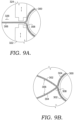
- FIG. 9B shows the tail 306 with the lateral side 302 crossing over, and braided with, the medial side 304.
- the seam area 308 where the lateral side 302 is braided together with the medial side 302 could extend further, as shown in FIG. 9A .
- the tail 306 is placed through slot 318 to extend between sonic welding horn 322 and sonic welding anvil 324.
- tension may be applied to tail 306, as indicated by arrow 326.
- First back plate 314 and second back plate 316 can then be moved toward one another, until sonic welding horn 322 and sonic welding anvil 324 engage the tail 306.
- first back plate 314 and second back plate 316 remain stationary, while the sonic welding horn 322 and sonic welding anvil 324 move toward and away from one another within their respective back plates 314, 316.
- the sonic welding horn 322 and the sonic welding anvil 324 are thus able to selectively engage the braided yarns of tail 306.
- the sonic welding apparatus can be activated to join the yarns of the braided article of footwear 100 along heel axis 308.
- the sonic welding horn 322 and sonic welding anvil 324 operate to join and sever the yarns of the braided article of footwear 100 along the braid axis 308.
- FIG. 10 illustrates the article of footwear 100 after the yarns from the lateral side 302 are joined with the yarns from the medial side 304 along the heel axis 308.
- the heel axis 308 presents a seam 330 that allows the lateral side 302 and the medial side 304 to join while appearing to be a continuous braided structure.
- FIG. 10B shows a fused zone 332 that extends along seam 330.
- the fused zone 332 represents the joining of the yarns on the lateral side 302 fused to the yarns on the medial side 304 to prevent the braid from unraveling.
- the braid pattern of the lateral side 302 in one aspect, mates with the braid pattern of the medial side 304.
- the braided yarns from the lateral side 302 appear to be continuous with the braided yarns from the medial side 304.
- the heel axis is a strong seam that does not present a raised seam that needs further processing, such as requiring a taped seam.
- a unitary upper is formed that allows forces from the lateral side 302 to be transmitted to the medial side 304, and vice versa.
- a method 400 for manufacturing a braided upper for an article of footwear is shown in FIG. 11 .
- the method includes positioning a braided upper having a heel axis into a finishing jig, as shown at block 402.
- the method continues at block 404 by positioning the heel axis adjacent an alignment mechanism associated with the jig.
- the method continues at block 406 by activating a joining mechanism associated with the jig to join the yarns associated with a medial side of the upper to the yarns associated with a lateral side of the upper along the heel axis.
- the method continues by severing any yarns exterior of the joint formed by the joined yarns along the heel axis.
Landscapes
- Engineering & Computer Science (AREA)
- Textile Engineering (AREA)
- Chemical & Material Sciences (AREA)
- Materials Engineering (AREA)
- Manufacturing & Machinery (AREA)
- Braiding, Manufacturing Of Bobbin-Net Or Lace, And Manufacturing Of Nets By Knotting (AREA)
Description
- The present invention relates to a heel-axis finishing system for forming a braided footwear upper, an upper for an article of footwear comprising a braided upper and a method for forming a heel axis on a braided footwear upper.
- Traditional shoes are often made from textiles or materials that have uppers that are cut to a desired shape and stitched together. Newer methods also now include forming shoe uppers from a knitted textile. Still newer methods involve braiding a tubular textile for use as the shoe upper. Aspects herein relate to braiding tubular structures that in some aspects are used in articles of footwear.
-
US 2016/345676 A1 describes a braiding machine and method of forming an upper that includes braiding over a forming mandrel located adjacent to a ring. The braiding machine being capable of forming intricate braided structures. -
US 2014/377488 A1 describes a plexus of filaments which is composed of groups of filaments, whose filament members are linked together, in a repetitious pattern, and whose filaments may be interlaced or linked to bisecting groups of filaments, creating a patterned plexus whose filament members generally follow spiraling paths, while linking with neighboring filaments, creating a group, or interlaced groups, of tension distributive filaments within a plexus of filaments; and a method of producing said filament structures for a variety of uses including composite structures with tension displacement properties, and sporting goods requiring conformal load distribution with minimal weight; such as, running shoes. - The present invention is defined by a heel-axis finishing system for forming a braided footwear upper according to the appended claim 1, an upper for an article of footwear comprising a braided upper according to the appended claim 5 and a method for forming a heel axis on a braided footwear upper according to the appended
claim 10. Further embodiments are defined by the appended dependent claims. - Aspects herein are described in detail below with reference to the attached drawing figures, wherein:
-
FIG. 1 depicts a schematic view of an exemplary braiding machine; -
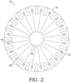
FIG. 2 depicts a schematic top view of an exemplary braiding machine, illustrating the carriages and rotor metals; -
FIG. 3 depicts a view similar toFIG. 2 , but with the rotor metals moving the carriages; -
FIG. 4 depicts a view similar toFIG. 3 , but showing the completion of the exemplary movement ofFIG. 3 ; -
FIG. 5 depicts an article of footwear, in accordance with aspects herein; -
FIG. 6 depicts a perspective view of an exemplary braiding machine having a lead bobbin or spool in a first position, in accordance with aspects herein; -
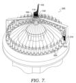
FIG. 7 depicts a perspective view of an exemplary braiding machine having a lead spool in a second position, in accordance with aspects herein; -
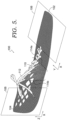
FIG. 8 depicts a perspective view of an exemplary braided upper, shown with an unfinished heel area, in accordance with aspects herein; -
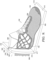
FIG. 9 depicts a perspective view of the exemplary braided upper ofFIG. 8 , shown in a finishing jig, in accordance with aspects herein; -
FIG. 9A depicts an enlarged view of a portion ofFIG. 9 ; -
FIG. 9B depicts an enlarged portion of the tail of the braided upper in the heel area; -
FIG. 10 depicts a perspective view of the exemplary braided upper ofFIG. 8 , shown with a finished heel area, in accordance with aspects herein; -
FIG. 10A depicts an enlarged view of a portion ofFIG. 10 ; -
FIG. 10B depicts a side view of the portion ofFIG. 10A ; and -
FIG. 11 depicts a flow chart of an exemplary method of forming an article of footwear having a braided upper with a finished heel axis, in accordance with aspects herein. - The present invention provides a heel-axis finishing system for forming a braided footwear upper having at least a medial side and a lateral side, and a toe end and a heel end. The braided footwear is made from a number of yarns that are braided together. The heel axis finishing system includes an alignment mechanism that orients the medial side of the upper and the lateral side of the braided upper at the heel end. The lateral side and the medial side come together at the heel and form a heel axis. A joining mechanism is associated with the alignment mechanism. The joining mechanism couples at least one braided yarn from the medial side to at least one braided yarn from the lateral side along the heel axis. In some aspects, the alignment mechanism includes a jig that aligns the medial side and the lateral side at the heel axis. According to the invention the joining mechanism is a sonic welding apparatus that severs and fuses the yarns along the heel axis to present a finished seam. By fusing the yarns as they are severed, when they are properly aligned, the heel area transitions from the medial side to the lateral side with an appearance of seamlessness.
- According to the invention, an article of footwear is provided that has a unitary, braided upper. The upper has a medial side, a lateral side, a toe end, and a heel end opposite the toe end. The braided upper has a joined heel axis along a joinder line where the lateral side and the medial side meet at the heel end. The joinder line forms a heel axis that, in one aspect, has at least one braided yarn from the medial side coupled to at least one braided yarn from the lateral side. In some aspects, the heel axis presents a transition from the medial side to the lateral side.
- Braiding is a process of interlacing or interweaving three or more yarns diagonally to a product axis in order to obtain a thicker, wider, or stronger product or in order to cover (overbraid) some profile. Interlacing diagonally means that the yarns make an angle with the product axis, which can be between 1o and 89o but is usually in the range of 30o - 80o. This angle is called the braiding angle. Braids can be linear products (ropes), hollow tubular shells, or solid structures (one, two, or three-dimensional textiles) with constant or variable cross-sections, and of closed or open appearance.
- As used herein, the yarns used for braiding may be formed of different materials having different properties. The properties that a particular yarn will impart to an area of a braided component partially depend upon the materials that form the yarn. Cotton, for example, provides a softer product, natural aesthetics, and biodegradability. Elastane and stretch polyester each provide substantial stretch and recovery, with stretch polyester also providing recyclability. Rayon provides high luster and moisture absorption. Wool also provides high moisture absorption, in addition to insulating properties and biodegradability. Nylon is a durable and abrasion-resistant material with relatively high strength. Polyester is a hydrophobic material that also provides relatively high durability. In addition to materials, other aspects of the yarn selected for formation of a braided component may affect the properties of the braided component. For example, a yarn may be a monofilament or a multifilament. The yarn may also include separate filaments that are each formed of different materials. In addition, the yarn may include filaments that are each formed of two or more different materials, such as a bicomponent yarn with filaments having a sheath-core configuration or two halves formed of different materials.
- As stated above, braided structures can be formed as tubular braids on a braiding machine, such as a radial, axial, or lace braiding machine. One example of a lace braiding machine can be found in
Ichikawa, EP 1 486 601, granted May 9, 2007 , entitled "Torchon Lace Machine," andEP No. 2 657 384, published Oct. 30, 2013 , entitled "Torchon Lace Machine." The upper portion of anexemplary braiding machine 10 is shown inFIG. 1 .Braiding machine 10 includes a plurality ofspools 12. In some embodiments, thespools 12 carry theyarn 14 selected for braiding. Theyarns 14 from individual spools are selectively interlaced or intertwined with one another by thebraiding machine 10. This interlacing or intertwining of strands forms abraided structure 16, as further described below. Each of thespools 12 is supported and constrained by atrack 18 about the circumference of thebraiding machine 10. Eachspool 12 has a tensioner 20 (shown schematically inFIG. 1 ) that operates, along with aroller 22, to maintain a desired tension in theyarns 14 and thebraided structure 16. As theyarns 14 extend upwardly, they pass through abraid ring 24 that is generally considered the braiding point. The braiding point is defined as the point or area whereyarns 14 consolidate to formbraid structure 16. At ornear ring 24, the distance betweenyarns 14 fromdifferent spools 12 diminishes. As the distance betweenyarns 14 is reduced, theyarns 14 intermesh or braid with one another in a tighter fashion and are pulled linearly byroller 22. - As best seen in
FIG. 2 , eachspool 12 is carried and supported by acarriage 26. Eachspool 12 is movable about the circumference of thetrack 18 byrotor metals 28. As described on the Torchon Lace Machine referenced previously, and disclosed inEP 1 486 601 , each of therotor metals 28 can be moved clockwise or counterclockwise. In contrast to radial braiding machines or fully non-jacquard machines, in a lace braiding machine, each rotor metal is not intermeshed with the adjacent rotor metal. Instead, eachrotor metal 28 may be selectively independently movable. As can be seen by comparingFIG. 2 to FIG. 4 , as therotor metals 28 rotate, they move thecarriages 26, and thus thespools 12 supported on thecarriages 26, by moving them about the circumference of thetrack 18. Thebraiding machine 10 is programmable such that theindividual rotor metals 28 rotate thecarriages 26, and thus thespools 12, to move them about the circumference of thetrack 18. As anindividual spool 12 moves relative to anadjacent spool 12, theyarns 14 carried on thespools 12 interweave to create a desired braid pattern. The movement ofspools 12 may be preprogrammed to form particular shapes, designs, and thread densities of a braided component or portions of a braided component. By varying the rotation and location ofindividual spools 12, various braid configurations may be formed. Such an exemplary braiding machine may form intricate braid configurations including both jacquard and non-jacquard braid configurations or geometries. Such configurations and geometries offer design possibilities beyond those offered by other textiles, such as knitting. - In some aspects, the size of braiding
machine 10 may be varied. It should be understood that thebraiding machine 10 shown and described is for illustrative purposes only. In some aspects, braidingmachine 10 may be able to accept 144 carriages, although other sizes of braiding machines, carrying different numbers of carriages and spools, is possible and is within the scope of this disclosure. By varying the number of carriages and spools within a braiding machine, the density of the braided structure as well as the size of the braided component may be altered. - Turning now to
FIG. 5 , an exemplary article offootwear 100 is depicted as having afirst end 102 and asecond end 104. In accordance with aspects herein, thefirst end 102 may correspond to a portion of the article offootwear 100 adapted to cover the toes of a wearer, while thesecond end 104 may correspond to a portion of the article offootwear 100 adapted to cover a heel or ankle end of a wearer. In accordance with the aspects discussed throughout this disclosure, the article offootwear 100 is generally braided from afirst end 102 to (towards) asecond end 104. In other words, the article offootwear 100 is generally braided from a toe end to an ankle end. However, it is envisioned that thefirst end 102 of the article offootwear 100 and thesecond end 104 of the article offootwear 100 may be reversed, such that the article of footwear is braided from an ankle end to a toe end of the article of footwear. - With continued reference to
FIG. 5 , thefirst end 102 of the article offootwear 100 generally corresponds to a first plane ofbraiding 106, while thesecond end 104 of the article of footwear generally corresponds to a second plane ofbraiding 108. As depicted inFIG. 5 , the first plane ofbraiding 106 is generally placed in an X-Y orientation, while the second plane ofbraiding 108 is generally placed in an X-Z orientation. - However, other orientations of the first plane of
braiding 106 and second plane ofbraiding 108 are considered to be within the scope of this disclosure. For example, the first plane ofbraiding 106 may be placed in an X-Z orientation, while the second plane ofbraiding 108 may be placed in a Y-Z orientation or an X-Y orientation. Regardless of the exact planes of braiding selected, the important aspect of the planes of braiding is that the first plane ofbraiding 106 and the second plane ofbraiding 108 are perpendicular to each other, such that a "Mobius twist" is performed to rotate from the first plane of braiding 106 to the second plane ofbraiding 108. However, aspects in which the first plane ofbraiding 106 and the second plane ofbraiding 108 are not perpendicular are considered to be within the scope of this disclosure. For example, the first plane ofbraiding 106 and the second plane ofbraiding 108 may be offset 45 degrees from one another, or may be offset any other amount between 0 and 90 degrees from each other. Generally, the article of footwear will have the greatest resistance to stretch in a direction that aligns to the plane of braiding used to manufacture that portion of the article of footwear. In other words, the amount of "Mobius twist" performed changes the functional characteristics of the article of footwear created by the methods described herein. - In accordance with aspects herein, the "Mobius twist" is generally performed at a
transition point 110 of the article of footwear, which generally refers to a point of the article of footwear in which the first plane ofbraiding 106 and second plane of braiding 108 intersect. In some aspects, the first plane ofbraiding 106 may transition to the second plane of braiding 108 instantaneously at thetransition point 110. Thetransition point 110 may be located between 5.08 and 15.24 cm (2 and 6 inches) from thefirst end 102 of the article of footwear. However, in some aspects, the first plane ofbraiding 106 may gradually morph into the second plane ofbraiding 108. In this aspect, thetransition point 110 may be more accurately referred to as atransition section 112, wherein thetransition section 112 has abeginning transition point 114a and an endingtransition point 114b. Similar to thetransition point 110, the beginningtransition point 114a may be located between 5.08 and 15.24 cm (2 and 6 inches) from thefirst end 102 of the article of footwear. - Thus far in this disclosure, the discussion with respect to
FIG. 5 has focused on manufacturing the exemplary article offootwear 100 that comprises a first section braided with a plurality of yarns in a first direction, which corresponds to the first plane ofbraiding 106. Next, the exemplary article of footwear comprises a second section braided with a plurality of yarns in a second direction, which corresponds to the second plane ofbraiding 108. Further, the exemplary article offootwear 100 further comprises thetransition section 112 positioned between thefirst section end 102 and thesecond end 104, wherein thetransition section 112 further comprises thebeginning transition point 114a proximate the first section and the endingtransition point 114b proximate the second section, wherein the plurality of yarns of thetransition section 112 linearly transitions from the first direction, or the first plane ofbraiding 106, to the second direction, or second plane ofbraiding 108. In accordance with aspects herein, transitioning linearly refers to the angle of the yarns rotating smoothly between perpendicular directions, the first direction and the second direction, over the length of thetransition section 112. Alternatively, the plurality of yarns of thetransition section 112 may transition in a non-linear manner, in which the angle of the yarns rotate quickly in one part of thetransition section 112, and rotate less quickly in another part of thetransition section 112. - Turning now to
FIG. 6 , anautomated braiding machine 200, similar to those shown inFIGS. 1-4 , is depicted. InFIG. 6 , the article offootwear 100 is shown as being braided beginning atfirst end 102. The automated braiding machine has abraid ring assembly 202 and a plurality ofspools 204 associated with thebraid ring assembly 202. The plurality ofspools 204 may be integrally formed into thebraid ring assembly 202, or provided separately and then coupled to thebraid ring assembly 202. In accordance with aspects herein, at least some of the plurality ofspools 204 may contain strands of braiding material, such as yarn, although it is generally desirable for the entirety of the plurality ofspools 204 to contain strands of braiding material. One of the plurality ofspools 204 has been shaded, and is referred to as the "lead spool" throughout this disclosure, for the purposes of tracking the positioning of the plurality ofspools 204 on thebraid ring assembly 200. As used throughout this disclosure, thebraid ring assembly 202 may have a first set of positions 210 (FIG. 6 ) and a second set of positions 212 (FIG. 7 ), where the second set ofpositions 212 is obtained by rotating the spools on thebraid ring assembly 202 from the first set ofpositions 210. The amount of rotation of spools on thebraid ring assembly 202 is completely variable based on the desired properties of the article of footwear. For example, the second set ofpositions 212 may be rotated 45 degrees from the first set ofpositions 210, or the second set ofpositions 212 may be rotated 90 degrees from the first set ofpositions 210. Alternatively, other intermediate amounts of rotation are considered to be within the scope of this disclosure. - For example, the lead spool can be tracked from the first set of
positions 210 as shown inFIG. 6 , to a second set ofpositions 212 as shownFIG. 7 , which depicts that the braid ring assembly has rotated approximately 90 degrees. As discussed previously, the article offootwear 100 is braided, beginning with afirst end 102, with the plurality ofspools 204 on thebraid ring assembly 202 in the first set ofpositions 210. In accordance with the "Mobius twist" described herein, braiding the article offootwear 100 with thebraid ring assembly 202 in the first set ofpositions 210 results in afirst end 102 of the article offootwear 100 being braided in afirst braiding plane 106, and wherein braiding the article offootwear 100 with thebraid ring assembly 202 in the second set ofpositions 212 results in thesecond end 104 of the article of footwear being braided in asecond braiding plane 108. - Turning now to
FIG. 7 , theautomated braiding machine 200 is depicted as manufacturing an article offootwear 100, after the "Mobius twist" has been performed. In other words, the article of footwear depicted inFIG. 7 has been fully braided in the first plane ofbraiding 106, has passed thetransition point 110, and is now braiding in the second plane ofbraiding 108, meaning that the positioning of the spools on thebraid ring assembly 202 are in the second set ofpositions 212. Accordingly,FIG. 7 depicts the automated braiding process after reaching and completely passing through thetransition point 110 of the article offootwear 100, or in other words, after the "Mobius twist" has been performed. - An exemplary article of
footwear 100 is shown inFIG. 8 , after removal from the braiding machine. The article offootwear 100 is shown disposed on a last 300 in an expanded condition that conforms to the shape of the last 300. As shown, the article offootwear 100 has thefirst end 102 in the toe area and thesecond end 104 in the heel area. The article offootwear 100 includes alateral side 302 and an oppositemedial side 304 extending from thefirst end 102 to thesecond end 104. As shown inFIG. 8 , the article offootwear 100, in an unfinished state, also includes atail 306 adjacent thesecond end 104. The article offootwear 100 can be braided, for example, as described above with respect toFIGS. 5-7 . For simplicity, the braiding is depicted inFIG. 8 somewhat schematically (such that thefirst braid plane 106 is not depicted). However, thetail 306, in one aspect, is braided in a vertical plane as described with respect tosecond braid plane 108 ofFIG. 5 . Thetail 306 is formed by braiding together the yarns forming thelateral side 302 and themedial side 304. The intersection of thelateral side 302 and themedial side 306 forms aheel axis 308. Thetail 306 is removed in a finishing process, described more fully below. - The article of
footwear 100 ofFIG. 8 is shown placed in ajig 310 inFIG. 9 . According to the invention,jig 310 has a base 312 that supports, and is coupled to, afirst back plate 314 and asecond back plate 316. According to the invention, first andsecond back plates base plate 312 such that they are spaced from one another, forming aslot 318. Moreover, in one aspect, first andsecond back plates base plate 312 such that they are allowed to move inward and outward to close oropen slot 318, within agroove 317, as indicated byarrows 320. Although shown with bothfirst back plate 314 andsecond back plate 316 as moveable with respect tobase 312, it should be understood that only one offirst back plate 314 orsecond back plate 316 could be moveable. Moreover, while shown as vertical, planar plates, first andsecond back plates heel axis 308. First backplate 314, in one aspect, has asonic welding horn 322 that extends into theslot 318. Second backplate 316 has a correspondingsonic welding anvil 324 that extends into the slot in a location to mate with thesonic welding horn 322. Thesonic welding horn 322 andsonic welding anvil 324 are shown schematically, and are coupled to a sonic welding apparatus (not shown). Thejig 310 serves to support the article offootwear 100 ofFIG. 8 such that thetail 306 is aligned with, and extends through, theslot 318. Thejig 310 operates as an alignment mechanism to consistently position thetail 306 with respect to thebase 312 and the first andsecond back plates -
FIG. 9B shows thetail 306 with thelateral side 302 crossing over, and braided with, themedial side 304. Theseam area 308 where thelateral side 302 is braided together with themedial side 302 could extend further, as shown inFIG. 9A . As shown in the enlarged area ofFIG. 9A , in one aspect, thetail 306 is placed throughslot 318 to extend betweensonic welding horn 322 andsonic welding anvil 324. In one aspect, tension may be applied totail 306, as indicated byarrow 326. First backplate 314 andsecond back plate 316 can then be moved toward one another, untilsonic welding horn 322 andsonic welding anvil 324 engage thetail 306. In one aspect,first back plate 314 andsecond back plate 316 remain stationary, while thesonic welding horn 322 andsonic welding anvil 324 move toward and away from one another within theirrespective back plates sonic welding horn 322 and thesonic welding anvil 324 are thus able to selectively engage the braided yarns oftail 306. In this condition, the sonic welding apparatus can be activated to join the yarns of the braided article offootwear 100 alongheel axis 308. In one aspect, thesonic welding horn 322 andsonic welding anvil 324 operate to join and sever the yarns of the braided article offootwear 100 along thebraid axis 308. -
FIG. 10 illustrates the article offootwear 100 after the yarns from thelateral side 302 are joined with the yarns from themedial side 304 along theheel axis 308. As shown in the enlargement inFIG. 10A , after the yarns from thelateral side 302 are joined with the yarns from themedial side 304, and the remainder of thetail 306 is severed from the article offootwear 100, theheel axis 308 presents aseam 330 that allows thelateral side 302 and themedial side 304 to join while appearing to be a continuous braided structure.FIG. 10B shows a fusedzone 332 that extends alongseam 330. The fusedzone 332 represents the joining of the yarns on thelateral side 302 fused to the yarns on themedial side 304 to prevent the braid from unraveling. So, the braid pattern of thelateral side 302, in one aspect, mates with the braid pattern of themedial side 304. In other words, the braided yarns from thelateral side 302 appear to be continuous with the braided yarns from themedial side 304. With this configuration, the heel axis is a strong seam that does not present a raised seam that needs further processing, such as requiring a taped seam. Further, by joining yarns from thelateral side 302 to themedial side 304, a unitary upper is formed that allows forces from thelateral side 302 to be transmitted to themedial side 304, and vice versa. Other methods of joining and severing the yarns from thelateral side 302 and themedial side 304, beyond sonic welding, could also be used. - A
method 400 for manufacturing a braided upper for an article of footwear is shown inFIG. 11 . The method includes positioning a braided upper having a heel axis into a finishing jig, as shown atblock 402. Once in the jig, the method continues atblock 404 by positioning the heel axis adjacent an alignment mechanism associated with the jig. In this position, the method continues atblock 406 by activating a joining mechanism associated with the jig to join the yarns associated with a medial side of the upper to the yarns associated with a lateral side of the upper along the heel axis. As shown atblock 408, the method continues by severing any yarns exterior of the joint formed by the joined yarns along the heel axis. - From the foregoing, it will be seen that this invention is one well adapted to attain all the ends and objects hereinabove set forth together with other advantages which are obvious and which are inherent to the structure.
- It will be understood that certain features and sub-combinations are of utility and may be employed without reference to other features and sub-combinations. This is contemplated by and is within the scope of the claims.
- Since many possible embodiments may be made of the invention without departing from the scope of the claims thereof, it is to be understood that all matter herein set forth or shown in the accompanying drawings is to be interpreted as illustrative and not in a limiting sense.
Claims (12)
- A heel-axis (308) finishing system for forming a braided footwear upper comprising:an alignment mechanism (310) configured to orient a medial side (304) of a braided upper with a lateral side (302) of the braided upper at a heel end (104) of the braided upper; anda joining mechanism associated with the alignment mechanism,said joining mechanism configured to couple a first braided yarn of the medial side (304) to a first braided yarn of the lateral side (302) along a heel axis (308),wherein the alignment mechanism comprises a base (312) and a pair of back plates (314), (316) coupled to the base in spaced apart relation to define a slot (318) and wherein the joining mechanism is a sonic welder.
- The heel-axis (308) finishing system of claim 1, wherein at least one of the pair of back plates (314), (316) is slidingly coupled to the base (312).
- The heel-axis (308) finishing system of claim 2, wherein both of the back plates (314), (316) are slidingly coupled to the base (312).
- The heel-axis (308) finishing system of claim 3, wherein the sonic welder comprises a sonic welding anvil (324) housed within one of the pair of back plates (314), (316), and a sonic welding horn (322) housed within the other of the pair of back plates, the sonic anvil and sonic horn extending into the defined slot.
- An upper for an article of footwear comprising: a braided upper comprisinga unitary, braided structure (16) having a lateral side (302) opposite a medial side (304) and a heel end opposite a toe end,wherein the braided upper comprises a joined heel axis (308) between the lateral side (302) and the medial side (304) proximate the heel end of the braided upper,said joined heel axis (308) comprising at least a first braided yarn of the lateral side (302) aligned and coupled, by a joining mechanism that is a sonic welder and associated with the alignment mechanism that comprises a base (312) and a pair of back plates (314), (316) coupled to the base in spaced apart relation to define a slot (318), to at least a first braided yarn of the medial side (304) at the joined heel axis (308).
- The upper for an article of footwear of claim 5, wherein the joined heel axis (308) presents a vertical transition seam from the lateral side (302) to the medial side (304).
- The upper for an article of footwear of claim 6, wherein the braided structure of the medial side (304) and the braided structure of the lateral side (302) are configured to mate with one another at the heel axis (308).
- The upper for an article of footwear of claim 7, wherein the joined heel axis (308) comprises yarns from the medial side (304) sonically welded to yarns from the lateral side (302).
- The upper for an article of footwear of claim 5, wherein the toe end presents a seam oriented orthogonally to the joined heel axis (308).
- A method for forming a heel axis (308) on a braided footwear upper, comprising:placing a braided upper on an alignment mechanism configured to orient a medial side (304) of a braided upper with a lateral side (302) of the braided upper at a heel end of the braided upper;and joining at least a first braided yarn of the medial side (304) to a first braided yarn of the lateral side (302) along a heel axis (308),wherein the alignment mechanism comprises a base (312) and a pair of back plates (314), (316) coupled to the base in spaced apart relation to define a slot (318) and wherein the joining step comprises activating a sonic welder along the heel axis (308).
- The method of forming a heel axis on a braided footwear upper of claim 10, further comprising removing at least a portion of the braided upper along the heel axis (308).
- The method of forming a heel axis on a braided footwear upper of claim 11, wherein the removing step includes activating a sonic welding apparatus along the length of the heel axis (308).
Applications Claiming Priority (3)
| Application Number | Priority Date | Filing Date | Title |
|---|---|---|---|
| US201762512449P | 2017-05-30 | 2017-05-30 | |
| US15/991,844 US20180343958A1 (en) | 2017-05-30 | 2018-05-29 | Braided upper for footwear with finished heel axis |
| PCT/US2018/035113 WO2018222703A1 (en) | 2017-05-30 | 2018-05-30 | Braided upper for footwear with finished heel axis |
Publications (2)
| Publication Number | Publication Date |
|---|---|
| EP3582644A1 EP3582644A1 (en) | 2019-12-25 |
| EP3582644B1 true EP3582644B1 (en) | 2023-12-20 |
Family
ID=62705694
Family Applications (1)
| Application Number | Title | Priority Date | Filing Date |
|---|---|---|---|
| EP18733416.4A Active EP3582644B1 (en) | 2017-05-30 | 2018-05-30 | Braided upper for footwear with finished heel axis |
Country Status (4)
| Country | Link |
|---|---|
| US (1) | US20180343958A1 (en) |
| EP (1) | EP3582644B1 (en) |
| CN (1) | CN110678096B (en) |
| WO (1) | WO2018222703A1 (en) |
Families Citing this family (4)
| Publication number | Priority date | Publication date | Assignee | Title |
|---|---|---|---|---|
| US11457685B2 (en) | 2017-05-30 | 2022-10-04 | Nike, Inc. | Double layer, single tube braid for footwear upper |
| US10905189B2 (en) | 2017-05-31 | 2021-02-02 | Nike, Inc. | Braided article of footwear incorporating flat yarn |
| DE102017210821B4 (en) * | 2017-06-27 | 2025-10-09 | Adidas Ag | Specially designed braided hose |
| US11439206B2 (en) * | 2019-12-17 | 2022-09-13 | Under Armour, Inc. | Method of making an article of footwear with braided upper |
Family Cites Families (27)
| Publication number | Priority date | Publication date | Assignee | Title |
|---|---|---|---|---|
| JP4106308B2 (en) | 2003-06-10 | 2008-06-25 | 株式会社市川鉄工 | Torsion racing machine |
| CN101348971A (en) * | 2003-06-23 | 2009-01-21 | 帝人纤维株式会社 | Woven or knitted fabric containing two different yarns and clothing comprising the same |
| EP1714567A3 (en) * | 2003-06-27 | 2007-09-19 | W.L. GORE & ASSOCIATES GmbH | Microseam |
| ITMI20062383A1 (en) * | 2006-12-12 | 2008-06-13 | Steps S L | METHOD FOR THE REALIZATION OF A GARMENT-BASED SUIT |
| CN102345210B (en) * | 2010-07-30 | 2013-07-24 | 财团法人纺织产业综合研究所 | Equipment and method for preparing three-dimensional nonwoven structure |
| JP5652821B2 (en) | 2010-12-22 | 2015-01-14 | 株式会社市川鉄工 | Torsion racing machine |
| CN202286527U (en) * | 2011-10-14 | 2012-07-04 | 匠能股份有限公司 | Structure improved shoes |
| US20130260104A1 (en) * | 2012-04-03 | 2013-10-03 | Nike, Inc. | Yarns, Threads, And Textiles Incorporating A Thermoplastic Polymer Material |
| US9227362B2 (en) * | 2012-08-23 | 2016-01-05 | General Electric Company | Braid welding |
| US9095186B2 (en) * | 2013-01-15 | 2015-08-04 | Nike, Inc. | Article of footwear incorporating braided tensile strands |
| US9226548B2 (en) * | 2013-01-15 | 2016-01-05 | Nike, Inc. | Spacer textile material with channels having multiple tensile strands |
| US9107478B2 (en) * | 2013-02-08 | 2015-08-18 | Nike, Inc. | Article of footwear having a tapered throat and transitional lacing |
| US9351540B2 (en) * | 2013-02-14 | 2016-05-31 | Nike, Inc. | Last with retractable pins |
| DE102013207163B4 (en) * | 2013-04-19 | 2022-09-22 | Adidas Ag | shoe upper |
| US10159297B2 (en) * | 2013-05-21 | 2018-12-25 | Bradford C. Jamison | Patterned plexus of filaments, method of producing and articles containing patterned filaments |
| US10863794B2 (en) * | 2013-06-25 | 2020-12-15 | Nike, Inc. | Article of footwear having multiple braided structures |
| US20140373389A1 (en) * | 2013-06-25 | 2014-12-25 | Nike, Inc. | Braided Upper With Overlays For Article Of Footwear |
| DE102013225745A1 (en) * | 2013-12-12 | 2015-06-18 | Robert Bosch Gmbh | Ultrasound joining method and ultrasonic joining device |
| CN203765212U (en) * | 2014-01-26 | 2014-08-13 | 临沂固德建筑科技有限公司 | Split type clamping device |
| US10383388B2 (en) * | 2014-03-07 | 2019-08-20 | Nike, Inc. | Article of footware with upper incorporating knitted component providing variable compression |
| CN205512684U (en) * | 2014-09-30 | 2016-08-31 | 耐克创新有限合伙公司 | Articles of footwear |
| TWI620517B (en) * | 2015-05-15 | 2018-04-11 | 耐克創新有限合夥公司 | Article of footwear incorporating a curved knitted lacing element and method of forming an upper of an article of footwear having a knitted component |
| US9976237B2 (en) * | 2015-05-18 | 2018-05-22 | Nike, Inc. | Sock with heel locating features |
| US10238176B2 (en) * | 2015-05-26 | 2019-03-26 | Nike, Inc. | Braiding machine and method of forming a braided article using such braiding machine |
| TWI727198B (en) * | 2015-05-29 | 2021-05-11 | 荷蘭商耐克創新有限合夥公司 | Article of footwear flat pattern and method of manufacturing article of footwear |
| US11103028B2 (en) * | 2015-08-07 | 2021-08-31 | Nike, Inc. | Multi-layered braided article and method of making |
| CN205143663U (en) * | 2015-11-09 | 2016-04-13 | 信泰(福建)科技有限公司 | Solid flies to knit shoes |
-
2018
- 2018-05-29 US US15/991,844 patent/US20180343958A1/en not_active Abandoned
- 2018-05-30 CN CN201880035149.XA patent/CN110678096B/en active Active
- 2018-05-30 EP EP18733416.4A patent/EP3582644B1/en active Active
- 2018-05-30 WO PCT/US2018/035113 patent/WO2018222703A1/en not_active Ceased
Also Published As
| Publication number | Publication date |
|---|---|
| WO2018222703A1 (en) | 2018-12-06 |
| CN110678096B (en) | 2022-12-09 |
| US20180343958A1 (en) | 2018-12-06 |
| CN110678096A (en) | 2020-01-10 |
| EP3582644A1 (en) | 2019-12-25 |
Similar Documents
| Publication | Publication Date | Title |
|---|---|---|
| CN205999582U (en) | Braider | |
| US20180343958A1 (en) | Braided upper for footwear with finished heel axis | |
| CN111372483B (en) | Multi-layer braided upper | |
| US9416467B2 (en) | Three-dimensional weaving system | |
| EP3303674B1 (en) | Method of forming a braided upper | |
| CN110691870B (en) | Braided article of footwear incorporating flat yarns | |
| EP3810839B1 (en) | Braided footwear with integrated laces and methods for their manufacture | |
| US20180255852A1 (en) | Article of apparel | |
| US20180343960A1 (en) | Method of manufacturing a bi-axial braided article of footwear | |
| EP3583260B1 (en) | Braided double layer tube for single layer footwear upper |
Legal Events
| Date | Code | Title | Description |
|---|---|---|---|
| STAA | Information on the status of an ep patent application or granted ep patent |
Free format text: STATUS: UNKNOWN |
|
| STAA | Information on the status of an ep patent application or granted ep patent |
Free format text: STATUS: THE INTERNATIONAL PUBLICATION HAS BEEN MADE |
|
| PUAI | Public reference made under article 153(3) epc to a published international application that has entered the european phase |
Free format text: ORIGINAL CODE: 0009012 |
|
| STAA | Information on the status of an ep patent application or granted ep patent |
Free format text: STATUS: REQUEST FOR EXAMINATION WAS MADE |
|
| 17P | Request for examination filed |
Effective date: 20190919 |
|
| AK | Designated contracting states |
Kind code of ref document: A1 Designated state(s): AL AT BE BG CH CY CZ DE DK EE ES FI FR GB GR HR HU IE IS IT LI LT LU LV MC MK MT NL NO PL PT RO RS SE SI SK SM TR |
|
| AX | Request for extension of the european patent |
Extension state: BA ME |
|
| DAV | Request for validation of the european patent (deleted) | ||
| DAX | Request for extension of the european patent (deleted) | ||
| STAA | Information on the status of an ep patent application or granted ep patent |
Free format text: STATUS: EXAMINATION IS IN PROGRESS |
|
| 17Q | First examination report despatched |
Effective date: 20210820 |
|
| P01 | Opt-out of the competence of the unified patent court (upc) registered |
Effective date: 20230515 |
|
| GRAP | Despatch of communication of intention to grant a patent |
Free format text: ORIGINAL CODE: EPIDOSNIGR1 |
|
| STAA | Information on the status of an ep patent application or granted ep patent |
Free format text: STATUS: GRANT OF PATENT IS INTENDED |
|
| RIC1 | Information provided on ipc code assigned before grant |
Ipc: D04C 3/48 20060101ALI20230620BHEP Ipc: D04C 3/40 20060101ALI20230620BHEP Ipc: D04C 1/08 20060101ALI20230620BHEP Ipc: A43D 8/08 20060101ALI20230620BHEP Ipc: A43B 23/04 20060101ALI20230620BHEP Ipc: A43B 23/02 20060101ALI20230620BHEP Ipc: A43B 1/04 20060101AFI20230620BHEP |
|
| INTG | Intention to grant announced |
Effective date: 20230710 |
|
| GRAS | Grant fee paid |
Free format text: ORIGINAL CODE: EPIDOSNIGR3 |
|
| GRAA | (expected) grant |
Free format text: ORIGINAL CODE: 0009210 |
|
| STAA | Information on the status of an ep patent application or granted ep patent |
Free format text: STATUS: THE PATENT HAS BEEN GRANTED |
|
| AK | Designated contracting states |
Kind code of ref document: B1 Designated state(s): AL AT BE BG CH CY CZ DE DK EE ES FI FR GB GR HR HU IE IS IT LI LT LU LV MC MK MT NL NO PL PT RO RS SE SI SK SM TR |
|
| REG | Reference to a national code |
Ref country code: GB Ref legal event code: FG4D |
|
| REG | Reference to a national code |
Ref country code: CH Ref legal event code: EP |
|
| REG | Reference to a national code |
Ref country code: DE Ref legal event code: R096 Ref document number: 602018062892 Country of ref document: DE |
|
| REG | Reference to a national code |
Ref country code: IE Ref legal event code: FG4D |
|
| PG25 | Lapsed in a contracting state [announced via postgrant information from national office to epo] |
Ref country code: GR Free format text: LAPSE BECAUSE OF FAILURE TO SUBMIT A TRANSLATION OF THE DESCRIPTION OR TO PAY THE FEE WITHIN THE PRESCRIBED TIME-LIMIT Effective date: 20240321 |
|
| REG | Reference to a national code |
Ref country code: LT Ref legal event code: MG9D |
|
| PG25 | Lapsed in a contracting state [announced via postgrant information from national office to epo] |
Ref country code: LT Free format text: LAPSE BECAUSE OF FAILURE TO SUBMIT A TRANSLATION OF THE DESCRIPTION OR TO PAY THE FEE WITHIN THE PRESCRIBED TIME-LIMIT Effective date: 20231220 |
|
| REG | Reference to a national code |
Ref country code: NL Ref legal event code: MP Effective date: 20231220 |
|
| PG25 | Lapsed in a contracting state [announced via postgrant information from national office to epo] |
Ref country code: ES Free format text: LAPSE BECAUSE OF FAILURE TO SUBMIT A TRANSLATION OF THE DESCRIPTION OR TO PAY THE FEE WITHIN THE PRESCRIBED TIME-LIMIT Effective date: 20231220 |
|
| PG25 | Lapsed in a contracting state [announced via postgrant information from national office to epo] |
Ref country code: LT Free format text: LAPSE BECAUSE OF FAILURE TO SUBMIT A TRANSLATION OF THE DESCRIPTION OR TO PAY THE FEE WITHIN THE PRESCRIBED TIME-LIMIT Effective date: 20231220 Ref country code: GR Free format text: LAPSE BECAUSE OF FAILURE TO SUBMIT A TRANSLATION OF THE DESCRIPTION OR TO PAY THE FEE WITHIN THE PRESCRIBED TIME-LIMIT Effective date: 20240321 Ref country code: FI Free format text: LAPSE BECAUSE OF FAILURE TO SUBMIT A TRANSLATION OF THE DESCRIPTION OR TO PAY THE FEE WITHIN THE PRESCRIBED TIME-LIMIT Effective date: 20231220 Ref country code: ES Free format text: LAPSE BECAUSE OF FAILURE TO SUBMIT A TRANSLATION OF THE DESCRIPTION OR TO PAY THE FEE WITHIN THE PRESCRIBED TIME-LIMIT Effective date: 20231220 Ref country code: BG Free format text: LAPSE BECAUSE OF FAILURE TO SUBMIT A TRANSLATION OF THE DESCRIPTION OR TO PAY THE FEE WITHIN THE PRESCRIBED TIME-LIMIT Effective date: 20240320 |
|
| REG | Reference to a national code |
Ref country code: AT Ref legal event code: MK05 Ref document number: 1641668 Country of ref document: AT Kind code of ref document: T Effective date: 20231220 |
|
| PG25 | Lapsed in a contracting state [announced via postgrant information from national office to epo] |
Ref country code: NL Free format text: LAPSE BECAUSE OF FAILURE TO SUBMIT A TRANSLATION OF THE DESCRIPTION OR TO PAY THE FEE WITHIN THE PRESCRIBED TIME-LIMIT Effective date: 20231220 |
|
| PG25 | Lapsed in a contracting state [announced via postgrant information from national office to epo] |
Ref country code: SE Free format text: LAPSE BECAUSE OF FAILURE TO SUBMIT A TRANSLATION OF THE DESCRIPTION OR TO PAY THE FEE WITHIN THE PRESCRIBED TIME-LIMIT Effective date: 20231220 Ref country code: RS Free format text: LAPSE BECAUSE OF FAILURE TO SUBMIT A TRANSLATION OF THE DESCRIPTION OR TO PAY THE FEE WITHIN THE PRESCRIBED TIME-LIMIT Effective date: 20231220 Ref country code: NO Free format text: LAPSE BECAUSE OF FAILURE TO SUBMIT A TRANSLATION OF THE DESCRIPTION OR TO PAY THE FEE WITHIN THE PRESCRIBED TIME-LIMIT Effective date: 20240320 Ref country code: NL Free format text: LAPSE BECAUSE OF FAILURE TO SUBMIT A TRANSLATION OF THE DESCRIPTION OR TO PAY THE FEE WITHIN THE PRESCRIBED TIME-LIMIT Effective date: 20231220 Ref country code: LV Free format text: LAPSE BECAUSE OF FAILURE TO SUBMIT A TRANSLATION OF THE DESCRIPTION OR TO PAY THE FEE WITHIN THE PRESCRIBED TIME-LIMIT Effective date: 20231220 Ref country code: HR Free format text: LAPSE BECAUSE OF FAILURE TO SUBMIT A TRANSLATION OF THE DESCRIPTION OR TO PAY THE FEE WITHIN THE PRESCRIBED TIME-LIMIT Effective date: 20231220 |
|
| PG25 | Lapsed in a contracting state [announced via postgrant information from national office to epo] |
Ref country code: IS Free format text: LAPSE BECAUSE OF FAILURE TO SUBMIT A TRANSLATION OF THE DESCRIPTION OR TO PAY THE FEE WITHIN THE PRESCRIBED TIME-LIMIT Effective date: 20240420 |
|
| PG25 | Lapsed in a contracting state [announced via postgrant information from national office to epo] |
Ref country code: CZ Free format text: LAPSE BECAUSE OF FAILURE TO SUBMIT A TRANSLATION OF THE DESCRIPTION OR TO PAY THE FEE WITHIN THE PRESCRIBED TIME-LIMIT Effective date: 20231220 Ref country code: AT Free format text: LAPSE BECAUSE OF FAILURE TO SUBMIT A TRANSLATION OF THE DESCRIPTION OR TO PAY THE FEE WITHIN THE PRESCRIBED TIME-LIMIT Effective date: 20231220 |
|
| PG25 | Lapsed in a contracting state [announced via postgrant information from national office to epo] |
Ref country code: SK Free format text: LAPSE BECAUSE OF FAILURE TO SUBMIT A TRANSLATION OF THE DESCRIPTION OR TO PAY THE FEE WITHIN THE PRESCRIBED TIME-LIMIT Effective date: 20231220 |
|
| PG25 | Lapsed in a contracting state [announced via postgrant information from national office to epo] |
Ref country code: SM Free format text: LAPSE BECAUSE OF FAILURE TO SUBMIT A TRANSLATION OF THE DESCRIPTION OR TO PAY THE FEE WITHIN THE PRESCRIBED TIME-LIMIT Effective date: 20231220 Ref country code: SK Free format text: LAPSE BECAUSE OF FAILURE TO SUBMIT A TRANSLATION OF THE DESCRIPTION OR TO PAY THE FEE WITHIN THE PRESCRIBED TIME-LIMIT Effective date: 20231220 Ref country code: RO Free format text: LAPSE BECAUSE OF FAILURE TO SUBMIT A TRANSLATION OF THE DESCRIPTION OR TO PAY THE FEE WITHIN THE PRESCRIBED TIME-LIMIT Effective date: 20231220 Ref country code: IT Free format text: LAPSE BECAUSE OF FAILURE TO SUBMIT A TRANSLATION OF THE DESCRIPTION OR TO PAY THE FEE WITHIN THE PRESCRIBED TIME-LIMIT Effective date: 20231220 Ref country code: IS Free format text: LAPSE BECAUSE OF FAILURE TO SUBMIT A TRANSLATION OF THE DESCRIPTION OR TO PAY THE FEE WITHIN THE PRESCRIBED TIME-LIMIT Effective date: 20240420 Ref country code: EE Free format text: LAPSE BECAUSE OF FAILURE TO SUBMIT A TRANSLATION OF THE DESCRIPTION OR TO PAY THE FEE WITHIN THE PRESCRIBED TIME-LIMIT Effective date: 20231220 Ref country code: CZ Free format text: LAPSE BECAUSE OF FAILURE TO SUBMIT A TRANSLATION OF THE DESCRIPTION OR TO PAY THE FEE WITHIN THE PRESCRIBED TIME-LIMIT Effective date: 20231220 Ref country code: AT Free format text: LAPSE BECAUSE OF FAILURE TO SUBMIT A TRANSLATION OF THE DESCRIPTION OR TO PAY THE FEE WITHIN THE PRESCRIBED TIME-LIMIT Effective date: 20231220 |
|
| PG25 | Lapsed in a contracting state [announced via postgrant information from national office to epo] |
Ref country code: PL Free format text: LAPSE BECAUSE OF FAILURE TO SUBMIT A TRANSLATION OF THE DESCRIPTION OR TO PAY THE FEE WITHIN THE PRESCRIBED TIME-LIMIT Effective date: 20231220 Ref country code: PT Free format text: LAPSE BECAUSE OF FAILURE TO SUBMIT A TRANSLATION OF THE DESCRIPTION OR TO PAY THE FEE WITHIN THE PRESCRIBED TIME-LIMIT Effective date: 20240422 |
|
| PG25 | Lapsed in a contracting state [announced via postgrant information from national office to epo] |
Ref country code: PT Free format text: LAPSE BECAUSE OF FAILURE TO SUBMIT A TRANSLATION OF THE DESCRIPTION OR TO PAY THE FEE WITHIN THE PRESCRIBED TIME-LIMIT Effective date: 20240422 Ref country code: PL Free format text: LAPSE BECAUSE OF FAILURE TO SUBMIT A TRANSLATION OF THE DESCRIPTION OR TO PAY THE FEE WITHIN THE PRESCRIBED TIME-LIMIT Effective date: 20231220 |
|
| REG | Reference to a national code |
Ref country code: DE Ref legal event code: R097 Ref document number: 602018062892 Country of ref document: DE |
|
| PG25 | Lapsed in a contracting state [announced via postgrant information from national office to epo] |
Ref country code: DK Free format text: LAPSE BECAUSE OF FAILURE TO SUBMIT A TRANSLATION OF THE DESCRIPTION OR TO PAY THE FEE WITHIN THE PRESCRIBED TIME-LIMIT Effective date: 20231220 |
|
| PLBE | No opposition filed within time limit |
Free format text: ORIGINAL CODE: 0009261 |
|
| STAA | Information on the status of an ep patent application or granted ep patent |
Free format text: STATUS: NO OPPOSITION FILED WITHIN TIME LIMIT |
|
| PG25 | Lapsed in a contracting state [announced via postgrant information from national office to epo] |
Ref country code: SI Free format text: LAPSE BECAUSE OF FAILURE TO SUBMIT A TRANSLATION OF THE DESCRIPTION OR TO PAY THE FEE WITHIN THE PRESCRIBED TIME-LIMIT Effective date: 20231220 |
|
| PG25 | Lapsed in a contracting state [announced via postgrant information from national office to epo] |
Ref country code: SI Free format text: LAPSE BECAUSE OF FAILURE TO SUBMIT A TRANSLATION OF THE DESCRIPTION OR TO PAY THE FEE WITHIN THE PRESCRIBED TIME-LIMIT Effective date: 20231220 Ref country code: DK Free format text: LAPSE BECAUSE OF FAILURE TO SUBMIT A TRANSLATION OF THE DESCRIPTION OR TO PAY THE FEE WITHIN THE PRESCRIBED TIME-LIMIT Effective date: 20231220 |
|
| 26N | No opposition filed |
Effective date: 20240923 |
|
| REG | Reference to a national code |
Ref country code: CH Ref legal event code: PL |
|
| PG25 | Lapsed in a contracting state [announced via postgrant information from national office to epo] |
Ref country code: MC Free format text: LAPSE BECAUSE OF FAILURE TO SUBMIT A TRANSLATION OF THE DESCRIPTION OR TO PAY THE FEE WITHIN THE PRESCRIBED TIME-LIMIT Effective date: 20231220 |
|
| PG25 | Lapsed in a contracting state [announced via postgrant information from national office to epo] |
Ref country code: LU Free format text: LAPSE BECAUSE OF NON-PAYMENT OF DUE FEES Effective date: 20240530 |
|
| PG25 | Lapsed in a contracting state [announced via postgrant information from national office to epo] |
Ref country code: MC Free format text: LAPSE BECAUSE OF FAILURE TO SUBMIT A TRANSLATION OF THE DESCRIPTION OR TO PAY THE FEE WITHIN THE PRESCRIBED TIME-LIMIT Effective date: 20231220 Ref country code: LU Free format text: LAPSE BECAUSE OF NON-PAYMENT OF DUE FEES Effective date: 20240530 Ref country code: CH Free format text: LAPSE BECAUSE OF NON-PAYMENT OF DUE FEES Effective date: 20240531 |
|
| REG | Reference to a national code |
Ref country code: BE Ref legal event code: MM Effective date: 20240531 |
|
| PG25 | Lapsed in a contracting state [announced via postgrant information from national office to epo] |
Ref country code: IE Free format text: LAPSE BECAUSE OF NON-PAYMENT OF DUE FEES Effective date: 20240530 |
|
| PG25 | Lapsed in a contracting state [announced via postgrant information from national office to epo] |
Ref country code: BE Free format text: LAPSE BECAUSE OF NON-PAYMENT OF DUE FEES Effective date: 20240531 |
|
| PGFP | Annual fee paid to national office [announced via postgrant information from national office to epo] |
Ref country code: DE Payment date: 20250402 Year of fee payment: 8 |
|
| PGFP | Annual fee paid to national office [announced via postgrant information from national office to epo] |
Ref country code: FR Payment date: 20250401 Year of fee payment: 8 |
|
| PG25 | Lapsed in a contracting state [announced via postgrant information from national office to epo] |
Ref country code: CY Free format text: LAPSE BECAUSE OF FAILURE TO SUBMIT A TRANSLATION OF THE DESCRIPTION OR TO PAY THE FEE WITHIN THE PRESCRIBED TIME-LIMIT; INVALID AB INITIO Effective date: 20180530 |
|
| PG25 | Lapsed in a contracting state [announced via postgrant information from national office to epo] |
Ref country code: HU Free format text: LAPSE BECAUSE OF FAILURE TO SUBMIT A TRANSLATION OF THE DESCRIPTION OR TO PAY THE FEE WITHIN THE PRESCRIBED TIME-LIMIT; INVALID AB INITIO Effective date: 20180530 |
|
| PGFP | Annual fee paid to national office [announced via postgrant information from national office to epo] |
Ref country code: GB Payment date: 20260313 Year of fee payment: 9 |