EP3582337A1 - Connector - Google Patents
Connector Download PDFInfo
- Publication number
- EP3582337A1 EP3582337A1 EP19179915.4A EP19179915A EP3582337A1 EP 3582337 A1 EP3582337 A1 EP 3582337A1 EP 19179915 A EP19179915 A EP 19179915A EP 3582337 A1 EP3582337 A1 EP 3582337A1
- Authority
- EP
- European Patent Office
- Prior art keywords
- cable
- housing
- component
- bent
- rear housing
- Prior art date
- Legal status (The legal status is an assumption and is not a legal conclusion. Google has not performed a legal analysis and makes no representation as to the accuracy of the status listed.)
- Granted
Links
Images





Classifications
-
- H—ELECTRICITY
- H01—ELECTRIC ELEMENTS
- H01R—ELECTRICALLY-CONDUCTIVE CONNECTIONS; STRUCTURAL ASSOCIATIONS OF A PLURALITY OF MUTUALLY-INSULATED ELECTRICAL CONNECTING ELEMENTS; COUPLING DEVICES; CURRENT COLLECTORS
- H01R13/00—Details of coupling devices of the kinds covered by groups H01R12/70 or H01R24/00 - H01R33/00
- H01R13/40—Securing contact members in or to a base or case; Insulating of contact members
- H01R13/42—Securing in a demountable manner
- H01R13/422—Securing in resilient one-piece base or case, e.g. by friction; One-piece base or case formed with resilient locking means
-
- H—ELECTRICITY
- H01—ELECTRIC ELEMENTS
- H01R—ELECTRICALLY-CONDUCTIVE CONNECTIONS; STRUCTURAL ASSOCIATIONS OF A PLURALITY OF MUTUALLY-INSULATED ELECTRICAL CONNECTING ELEMENTS; COUPLING DEVICES; CURRENT COLLECTORS
- H01R13/00—Details of coupling devices of the kinds covered by groups H01R12/70 or H01R24/00 - H01R33/00
- H01R13/46—Bases; Cases
- H01R13/502—Bases; Cases composed of different pieces
-
- H—ELECTRICITY
- H01—ELECTRIC ELEMENTS
- H01R—ELECTRICALLY-CONDUCTIVE CONNECTIONS; STRUCTURAL ASSOCIATIONS OF A PLURALITY OF MUTUALLY-INSULATED ELECTRICAL CONNECTING ELEMENTS; COUPLING DEVICES; CURRENT COLLECTORS
- H01R13/00—Details of coupling devices of the kinds covered by groups H01R12/70 or H01R24/00 - H01R33/00
- H01R13/46—Bases; Cases
- H01R13/516—Means for holding or embracing insulating body, e.g. casing, hoods
-
- H—ELECTRICITY
- H01—ELECTRIC ELEMENTS
- H01R—ELECTRICALLY-CONDUCTIVE CONNECTIONS; STRUCTURAL ASSOCIATIONS OF A PLURALITY OF MUTUALLY-INSULATED ELECTRICAL CONNECTING ELEMENTS; COUPLING DEVICES; CURRENT COLLECTORS
- H01R13/00—Details of coupling devices of the kinds covered by groups H01R12/70 or H01R24/00 - H01R33/00
- H01R13/46—Bases; Cases
- H01R13/52—Dustproof, splashproof, drip-proof, waterproof, or flameproof cases
- H01R13/5205—Sealing means between cable and housing, e.g. grommet
-
- H—ELECTRICITY
- H01—ELECTRIC ELEMENTS
- H01R—ELECTRICALLY-CONDUCTIVE CONNECTIONS; STRUCTURAL ASSOCIATIONS OF A PLURALITY OF MUTUALLY-INSULATED ELECTRICAL CONNECTING ELEMENTS; COUPLING DEVICES; CURRENT COLLECTORS
- H01R13/00—Details of coupling devices of the kinds covered by groups H01R12/70 or H01R24/00 - H01R33/00
- H01R13/56—Means for preventing chafing or fracture of flexible leads at outlet from coupling part
-
- H—ELECTRICITY
- H01—ELECTRIC ELEMENTS
- H01R—ELECTRICALLY-CONDUCTIVE CONNECTIONS; STRUCTURAL ASSOCIATIONS OF A PLURALITY OF MUTUALLY-INSULATED ELECTRICAL CONNECTING ELEMENTS; COUPLING DEVICES; CURRENT COLLECTORS
- H01R13/00—Details of coupling devices of the kinds covered by groups H01R12/70 or H01R24/00 - H01R33/00
- H01R13/56—Means for preventing chafing or fracture of flexible leads at outlet from coupling part
- H01R13/562—Bending-relieving
-
- H—ELECTRICITY
- H01—ELECTRIC ELEMENTS
- H01R—ELECTRICALLY-CONDUCTIVE CONNECTIONS; STRUCTURAL ASSOCIATIONS OF A PLURALITY OF MUTUALLY-INSULATED ELECTRICAL CONNECTING ELEMENTS; COUPLING DEVICES; CURRENT COLLECTORS
- H01R13/00—Details of coupling devices of the kinds covered by groups H01R12/70 or H01R24/00 - H01R33/00
- H01R13/58—Means for relieving strain on wire connection, e.g. cord grip, for avoiding loosening of connections between wires and terminals within a coupling device terminating a cable
-
- H—ELECTRICITY
- H01—ELECTRIC ELEMENTS
- H01R—ELECTRICALLY-CONDUCTIVE CONNECTIONS; STRUCTURAL ASSOCIATIONS OF A PLURALITY OF MUTUALLY-INSULATED ELECTRICAL CONNECTING ELEMENTS; COUPLING DEVICES; CURRENT COLLECTORS
- H01R13/00—Details of coupling devices of the kinds covered by groups H01R12/70 or H01R24/00 - H01R33/00
- H01R13/46—Bases; Cases
- H01R13/502—Bases; Cases composed of different pieces
- H01R13/506—Bases; Cases composed of different pieces assembled by snap action of the parts
Definitions
- the present invention relates to a connector.
- a connector 301 including a connector cover 307 attached to a back end of a connector housing (housing) 303 and restraining an introduction direction of a cable 305 has been known.
- JP 2013-110025 A JP 2013-110025 A .
- a large gap 309 is present between the cable 305 extending from the housing 303 and the connector cover 307 mounted on the housing 303, and thus a bend radius of the cable 305 extending from the housing 303 while being bent is changed in some cases.
- An excessive bending stress is applied to the cable 305 due to the change in the bend radius, which is problematic.
- the present invention has been made to solve the problem described above, and an object of the present invention is to provide a connector in which a bend radius of a bent portion of a cable extending from a housing is small, the bent portion being in the vicinity of the housing, thereby making it possible to prevent an excessive bending stress from being applied to the cable.
- a connector includes: a housing into which a cable is inserted; and a rear housing mounted on the housing, configured to guide the cable extending from the housing to maintain shapes of portions of the cable, the portions being in the vicinity of the housing.
- the present invention it is possible to provide a connector in which a bend radius of a bent portion of a cable extending from a housing is small, the bent portion being in the vicinity of the housing, thereby making it possible to prevent an excessive bending stress from being applied to the cable.
- a connector 1 is used in, for example, a vehicle, and includes a housing 3 and a rear housing (rear holder) 5 as illustrated in FIGS. 1 to 4 .
- a predetermined direction in a space is defined as a front-back direction
- a predetermined direction orthogonal to the front-back direction is defined as a transverse direction
- a direction orthogonal to the front-back direction and the transverse direction is defined as a vertical direction.
- a cable 7 (one end portion of the cable 7 in a longitudinal direction) is inserted into the housing 3.
- the cable 7 has flexibility, and the cable 7 of which one end portion is fixed in (inserted into) the housing 3 extends from the housing 3 to a back side or a lower side.
- the rear housing 5 is mounted on the housing 3 to guide the cable 7. That is, the rear housing 5 is integrally mounted on the housing 3 to maintain shapes of portions (portions of the cable 7 in the vicinity of the housing) 15 and 17 of the cable 7 in the vicinity of the housing 3, for example, bent portions.
- the rear housing 5 is integrally mounted on the housing 3 in order to maintain desired shapes of the portions 15 and 17 of the cable 7 in the vicinity of the housing (more specifically, in order to maintain a desired bend radius of the cable).
- a sealing material 9 formed in a ring shape (for example, a cylindrical shape) is provided in the connector 1.
- the cable 7 is inserted into the sealing material 9.
- the sealing material 9 into which the cable 7 is inserted is mounted in the housing 3 together with the cable 7 to seal between the housing 3 and the cable 7.
- one end portion (front end portion) of the rear housing 5 is inserted into the housing 3 to thereby prevent the sealing material 9 from being detached from the housing 3.
- the shapes of the portions 15 and 17 (the portions in the vicinity of the housing 3) of the cable 7 are maintained by the rear housing 5 in order to prevent sealability (sealing performance) of the sealing material 9 from deteriorating as a gap is formed between the sealing material 9 and the housing 3, or a gap is formed between the sealing material 9 and the cable 7 due to deformation of the sealing material 9 caused by deformation of the portion of the cable 7 penetrating through the sealing material 9 (for example, deformation in which a bend radius of the cable 7 becomes excessively small or the like).
- the guiding of the cable 7 by the rear housing 5 is made as the cable 7 is inserted into a cylindrical portion (cylindrical portion of which an inner diameter is equal to or slightly larger than an outer diameter of the cable) 11 of the rear housing 5.
- the rear housing 5 is divided into at least two components by a first dividing surface 13 on which a central axis (a central axis of the cable 7 inserted into the cylindrical portion 11) of the cylindrical portion 11 is positioned. This is to allow the cable 7 to be fixed in the cylindrical portion 11 by bending and relatively moving the cable 7 in a radial direction of the cable 7 with respect to the cylindrical portion 11 of the rear housing 5, without relatively moving the cable 7 in the longitudinal direction with respect to the cylindrical portion 11 of the rear housing 5.
- the cable 7 extending from the housing 3 (sealing material 9) linearly extends only by a predetermined short distance and then is bent in an arc shape (for example, 1/4 arc; any length from 1/10 arc to 1/2 arc) so that the central axis of the cable 7 is positioned on one plane (for example, on the drawing of FIG. 4 ). It should be noted that a central axis of the linearly extending portion 15 of the cable 7 is also positioned on the one plane.
- the cable 7 extending from the housing 3 (sealing material 9) linearly extends only by a predetermined small distance in the vicinity of the housing 3 (sealing material 9) and then is bent in an arc shape, such that the portions (guided portions) 15 and 17 of the cable 7 in the vicinity of the housing 3 (sealing material 9) are guided by the rear housing 5.
- the central axis (coinciding with the central axis of the cable 7) of the cylindrical portion 11 is positioned on the first dividing surface 13 dividing the rear housing 5, and the first dividing surface 13 is orthogonal to the one plane on which the central axis of the cable 7 is positioned.
- the cable 7 extending from the housing 3 includes the portion 15 having a short cylindrical shape and the portion 17 having a cylindrical shape of which a central axis is bent in an arc shape.
- the cylindrical portion 11 of the rear housing 5 guides the portion (guided portion) 15 of the cable 7 linearly extending only by the predetermined small distance, and the portion (guided portion) 17 of the cable 7 bent in the arc shape.
- the rear housing 5 is divided into three components 19, 21, and 23.
- a first component 19 of the three divided components is one of the at least two components into which the rear housing 5 is divided by the first dividing surface 13, and is a component (a component of an upper side in FIG. 4 and the like) engaged with (in contact with) a convex surface of the cable 7 bent in the arc shape.
- a second component 21 of the three divided components is one (a component of a front side in FIG. 4 and the like) of two components into which a component (a component of a lower side in FIG. 4 and the like) engaged with (in contact with) a concave surface of the cable 7 bent in the arc shape, which is the other one of the at least two components into which the rear housing 5 is divided by the first dividing surface 13, is further divided by a second dividing surface 25.
- the second dividing surface 25 is positioned on a boundary between the portion 15 of the cable 7 linearly extending only by the predetermined short distance and the portion 17 of the cable 7 extending while being bent in the arc shape, and is a plane orthogonal to the central axis (front-back direction) of the cable 7.
- a third component 23 of the three divided components is the other one (a component of a back side in FIG. 4 and the like) of the two components into which the rear housing 5 is divided by the second dividing surface 25.
- the first and second components 19 and 21 are mounted on the housing 3 by relatively moving the first and second components 19 and 21 forward with respect to the housing 3 and inserting one end portions (front end portions) of the first and second components 19 and 21 into the housing 3 in a state in which the first component 19 and the second component 21 are combined (in surface-contact) with each other on the first dividing surface 13.
- the third component 23 is mounted on the housing 3 (the first and second components 19 and 21) by moving the third component 23 upwards with respect to the housing 3, combining the first and third components 19 and 23 with each other on the first dividing surface 13, and combining the second and third components 21 and 23 with each other on the second dividing surface 25 in a state in which the first and second components 19 and 21 are integrally mounted on the housing 3.
- the cable 7 includes a core wire 31 and an insulating sheath 33 covering the core wire 31.
- the insulating sheath 33 is removed and the core wire 31 is exposed at one end portion (front end portion) of the cable 7 in the longitudinal direction.
- a metallic terminal (for example, a female terminal) 35 is fixed to the exposed portion of the core wire 31.
- the housing 3 includes an outer housing 27 formed of an insulating material such as a synthetic resin and the like having rigidity, and an inner housing 29 formed of an insulating material such as a synthetic region and the like as well.
- the inner housing 29 is formed in a cylindrical shape, and is provided integrally with the outer housing 27 inside the outer housing 27.
- a first space 37 in which the terminal 35 is mounted, a second space 39 having a cylindrical shape, and a third space 41 having a cylindrical shape are connected to each other and sequentially aligned from the front side toward the back side inside the cylindrical inner housing 29.
- a central axis of the cylindrical second space 39 and a central axis of the cylindrical third space 41 coincide with each other and extend in the front-back direction.
- An inner diameter of the cylindrical third space 41 is larger than an inner diameter of the cylindrical second space 39.
- the terminal 35 is integrally mounted in the first space 37.
- the portion of the cable 7 linearly extending from the terminal 35 mounted in the first space 37 to the back side is inserted into the second space 39 and the third space 41.
- the central axis of the portion of the cable 7 linearly extending from the terminal 35 to the back side and the central axis of the second space 39 coincide with each other.
- the inner diameter of the second space 39 is larger than an outer diameter of the cable 7 (insulating sheath 33).
- the sealing material 9 and a portion (a portion of the front side) of a front end portion (cylindrical front end portion) 43 of the rear housing 5 are inserted into the third space 41.
- the sealing material 9 is formed in a cylindrical shape, an inner diameter of the sealing material 9 is slightly smaller than the outer diameter of the cable 7 (insulating sheath 33), and an outer diameter of the sealing material 9 is slightly larger than an inner diameter of the third space 41.
- the sealing material 9 In a state in which the sealing material 9 is mounted in the third space 41 and the cable 7 penetrates through the sealing material 9, the sealing material 9 is appropriately elastically deformed, abuts on a wall surface of the third space 41 with an energizing force, and abuts on an outer circumference of the cable 7 with an energizing force. As a result, sealability between the inner housing 29 and the cable 7 is secured.
- the sealing material 9 mounted in the third space 41 is positioned in the middle (middle portion) of the third space 41 or is positioned in the front side (front side portion) of the third space 41 in the front-back direction.
- the rear housing 5 is formed of an insulating material such as a synthetic resin and the like having rigidity, is formed in an integrated form, and includes the front end portion 43 described above and a back end portion 45.
- the front end portion 43 and the back end portion 45 form the cylindrical portion 11 described above.
- the front end portion 43 guides the guided portion 15 of the cable 7 extending linearly and the back end portion 45 guides the guided portion 17 of the cable 7 bent in the arc shape.
- An outer diameter of the portion of the front side of the front end portion 43 is equal to or slightly smaller than the inner diameter of the third space 41, and an inner diameter of the front end portion 43 is equal to or larger than the outer diameter of the cable 7.
- An outer diameter of the back end portion 45 is equal to, smaller than, or larger than the inner diameter of the third space 41.
- an inner diameter of the back end portion 45 is equal to or slightly larger than the outer diameter of the cable 7.
- the first component 19 of the cylindrical portion 11 is constituted by a portion (a semi-cylindrical portion of the upper side) of the front end portion 43 and a portion (a bent semi-cylindrical portion of the upper side) of the back end portion 45
- the second component 21 of the cylindrical portion 11 is constituted by the remaining portions (a semi-cylindrical portion of the lower side) of the front end portion 43
- the third component 23 is constituted by the remaining portion (a bent semi-cylindrical portion of the lower side) of the back end portion 45.
- Protruding portions 46 abutting on the inner housing 29 when the front end portion 43 of the rear housing 5 is inserted into the third space 41 to position the rear housing 5 in the front-back direction are provided on the back end portion of the first component 19 and the back end portion of the second component 21, respectively.
- an inner housing an inner housing in which the plurality of cables are fixed
- a rear housing a rear housing in which the plurality of cables are fixed
- engaged portions 47 protrude from the first component 19 and the second component 21 constituting the rear housing 5 in which the plurality of cables are fixed.
- the engaged portions 47 protrude forward from the first component 19 and the second component 21, respectively.
- small protrusions 44 formed in a flat plate shape are provided on opposite end portions and a middle portion (a portion between two guided cables 7) of the first component 19 guiding the two cables 7, in the transverse direction, respectively, and similarly, small protrusions 44 formed in a flat plate shape are provided on opposite end portions and a middle portion (a portion between the two guided cables 7) of the second component 21 guiding the two cables 7, in the transverse direction, respectively.
- the protrusion 44 provided on the middle portion of the first component 19 guiding the two cables 7, in the transverse direction, and the protrusion 44 provided on the middle portion of the second component 21 guiding the two cables 7, in the transverse direction are separate from each other in the vertical direction.
- each of the protrusions 44 is inserted into a groove (a groove formed as a portion of an inner wall of the cylindrical third space 41 swells outwards) (not illustrated) formed in the inner housing 29 to, for example, fit the groove without rattling.
- the protrusions 44 are provided, and the grooves corresponding to the protrusions 44 are also formed in the inner housing 29, similarly to the case where two cables 7 are guided.
- a plurality of locking portions 49 (for example, four locking portions) are provided on the first component 19 guiding two cables 7.
- the plurality of locking portions 49 protrude from the first component 19.
- a plurality of locked portions 51 (for example, four locked portions) are provided on the third component 23 guiding the two cables 7.
- the plurality of locking portions 49 are locked to the plurality of locked portions 51, respectively, such that the third component 23 is integrated with the first component 19 and the second component 21 (and the housing 3).
- two of the four locking portions 49 of the first component 19 are provided on opposite end portions of the first component 19 in the transverse direction, and the other two are provided on a middle portion of the first component 19 in the transverse direction.
- two of the four locked portions 51 of the third component 23 are provided on opposite end portions of the third component 23 in the transverse direction, and the other two are provided on a middle portion of the third component 23 in the transverse direction.
- the two locked portions 51 provided on the middle portion are also locked in addition to the two locked portions 51 provided on the opposite end portions in a state in which the third component 23 is mounted on the first component 19 and the second component 21 mounted on the inner housing 29, it is possible to prevent the rear holder 5 from being detached from the housing 3 (prevent the third component 23 from being detached from the first component 19) when an external force is applied due to unexpected catching or the like.
- One locking portion may be provided instead of the two locking portions 49 (49A) provided on the middle portion illustrated in FIG. 5B , and one locked portion may be provided instead of the two locked portions 51(51A) provided on the two middle portions illustrated in FIG. 7A .
- the locking portion 49 and the locked portion 51 are provided, similarly to the case where two cables 7 are guided.
- an exterior component 53 having a long cylindrical shape is mounted on a back end portion of the outer housing 27.
- the exterior component 53 covers the rear housing 5 and the cable 7, and a gap 55 is formed between the exterior component 53, and the rear housing 5 and the cable 7.
- the inner housing 29 is mounted on the outer housing 27, and a packing 57 is mounted on the inner housing 29.
- the packing 57 is a component to secure sealability between a connector (not illustrated) mounted on the connector 1 and the connector 1.
- a cap 59 is mounted on the inner housing 29 in order to prevent the terminal 35 from being detached from the inner housing 29.
- the cable 7 to which the terminal (a terminal electrically conducted with the core wire 31 of the cable 7) 35 is fixed is fixed in the inner housing 29.
- the terminal 35 is fitted in the first space 37 and the cable 7 extends from the terminal 35 to the back side in a state in which the fixing of the cable 7 is completed.
- the sealing material 9 is mounted in the inner housing 29 and the rear housing 5 is mounted on the inner housing 29 to prevent the sealing material 9 from being detached and guide the cable 7, thereby maintaining the shape of the cable 7.
- the rear housing 5 is mounted on the inner housing 29 in a manner in which the first component 19 and the second component 21 are mounted on the inner housing 29 first, and then the third component 23 is mounted on the first component 19 and the second component 21.
- the exterior component 53 is mounted on the outer housing 27 to cover the cable 7 and the rear housing 5.
- the cable 7 is guided by the rear housing 5, and is not bent even when an external force is applied to the cable 7 in the vicinity of the inner housing 29.
- the rear housing 5 is configured to allow the shapes of the portions 15 and 17 of the cable 7 extending from the housing 3 to be maintained, the portions 15 and 17 being in the vicinity of the housing 3, and thus, for example, a bend radius of the bent portion 17 of the cable 7 may not become smaller than a target value but be maintained and it is possible to prevent an excessive bend stress from being applied to the cable 7.
- the shape of the cable 7 (the shapes of the portions 15 and 17 in the vicinity of the housing 3) extending from the housing 3 is maintained, a degree of freedom in a layout when mounting the connector 1 in a vehicle is increased. For example, it is possible to appropriately change the shape of the cable 7 extending from the housing 3 only by changing a shape of the rear housing 5 (cylindrical portion 11).
- the sealing material 9 is provided, and the rear housing 5 allows the shape of the cable 7 (the shapes of the portions 15 and 17 in the vicinity of the housing 3) extending from the housing 3 to be maintained while preventing the sealing material 9 from being detached from the housing 3. Therefore, deformation of the sealing material 9 due to the deformation of the cable 7 does not occur, and it is possible to secure sealability between the housing 3 and the cable 7.
- the rear housing 5 is divided by the first dividing surface 13 on which the central axis of the cylindrical portion 11 is positioned, and thus the rear housing 5 can be mounted on the cable 7 bent in an arc shape and extending from the housing 3, while easily maintaining the arc shape of the cable 7.
- the rear housing 5 is divided into three components 19, 21, and 23, and the three components 19, 21, and 23 are mounted on the housing 3 in which the cable 7 is fixed according to the procedure described above, such that the rear housing 5 is easily mounted on the housing 3.
- the cable 7 is two-dimensionally bent in an arc shape (the central axis of the cable 7 is two-dimensionally bent in the arc shape) has been described by way of example.
- the cable 7 may also be three-dimensionally bent (the cable 7 may further be bent toward the front plane or the back plane of FIG. 4 ).
- the cable 7 may also be bent in a shape (for example, a curved shape) other than the arc shape.
Landscapes
- Details Of Connecting Devices For Male And Female Coupling (AREA)
- Connector Housings Or Holding Contact Members (AREA)
Abstract
Description
- The present invention relates to a connector.
- Conventionally, as illustrated in
FIG. 9 , aconnector 301 including aconnector cover 307 attached to a back end of a connector housing (housing) 303 and restraining an introduction direction of acable 305 has been known. - Here, a patent literature related to the technology according to the related art includes
JP 2013-110025 A - In the
conventional connector 301, alarge gap 309 is present between thecable 305 extending from thehousing 303 and theconnector cover 307 mounted on thehousing 303, and thus a bend radius of thecable 305 extending from thehousing 303 while being bent is changed in some cases. An excessive bending stress is applied to thecable 305 due to the change in the bend radius, which is problematic. - The present invention has been made to solve the problem described above, and an object of the present invention is to provide a connector in which a bend radius of a bent portion of a cable extending from a housing is small, the bent portion being in the vicinity of the housing, thereby making it possible to prevent an excessive bending stress from being applied to the cable.
- According to an aspect of the present invention, a connector includes: a housing into which a cable is inserted; and a rear housing mounted on the housing, configured to guide the cable extending from the housing to maintain shapes of portions of the cable, the portions being in the vicinity of the housing.
- According to the present invention, it is possible to provide a connector in which a bend radius of a bent portion of a cable extending from a housing is small, the bent portion being in the vicinity of the housing, thereby making it possible to prevent an excessive bending stress from being applied to the cable.
-
-
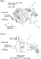
FIG. 1 is a perspective view illustrating a connector according to an embodiment of the present invention; -
FIG. 2 is a view when viewed in an arrow direction II ofFIG. 1 ; -
FIG. 3 is a view when viewed in an arrow direction III ofFIG. 1 ; -
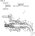
FIG. 4 is a view taken along line IV-IV inFIG. 3 ; -
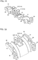
FIGS. 5A and 5B are perspective views illustrating a first component constituting a rear housing of the connector according to the embodiment of the present invention when viewed from different directions; -
FIG. 6 is a perspective view illustrating a second component constituting the rear housing of the connector according to the embodiment of the present invention; -
FIGS. 7A and 7B are perspective views illustrating a third component constituting a rear housing of the connector according to the embodiment of the present invention when viewed from different directions; -
FIG. 8 is a view illustrating a state in which an exterior component is mounted on the connector illustrated inFIG. 4 ; and -
FIG. 9 is a view illustrating a connector according to the related art. - A
connector 1 according to an embodiment of the present invention is used in, for example, a vehicle, and includes ahousing 3 and a rear housing (rear holder) 5 as illustrated inFIGS. 1 to 4 . - Here, for convenience of explanation, a predetermined direction in a space is defined as a front-back direction, a predetermined direction orthogonal to the front-back direction is defined as a transverse direction, and a direction orthogonal to the front-back direction and the transverse direction is defined as a vertical direction.
- A cable 7 (one end portion of the
cable 7 in a longitudinal direction) is inserted into thehousing 3. Thecable 7 has flexibility, and thecable 7 of which one end portion is fixed in (inserted into) thehousing 3 extends from thehousing 3 to a back side or a lower side. - The
rear housing 5 is mounted on thehousing 3 to guide thecable 7. That is, therear housing 5 is integrally mounted on thehousing 3 to maintain shapes of portions (portions of thecable 7 in the vicinity of the housing) 15 and 17 of thecable 7 in the vicinity of thehousing 3, for example, bent portions. - In more detail, the
rear housing 5 is integrally mounted on thehousing 3 in order to maintain desired shapes of theportions cable 7 in the vicinity of the housing (more specifically, in order to maintain a desired bend radius of the cable). - A sealing
material 9 formed in a ring shape (for example, a cylindrical shape) is provided in theconnector 1. Thecable 7 is inserted into the sealingmaterial 9. The sealingmaterial 9 into which thecable 7 is inserted is mounted in thehousing 3 together with thecable 7 to seal between thehousing 3 and thecable 7. - In addition, one end portion (front end portion) of the
rear housing 5 is inserted into thehousing 3 to thereby prevent the sealingmaterial 9 from being detached from thehousing 3. - The shapes of the
portions 15 and 17 (the portions in the vicinity of the housing 3) of thecable 7 are maintained by therear housing 5 in order to prevent sealability (sealing performance) of the sealingmaterial 9 from deteriorating as a gap is formed between the sealingmaterial 9 and thehousing 3, or a gap is formed between the sealingmaterial 9 and thecable 7 due to deformation of the sealingmaterial 9 caused by deformation of the portion of thecable 7 penetrating through the sealing material 9 (for example, deformation in which a bend radius of thecable 7 becomes excessively small or the like). - The guiding of the
cable 7 by therear housing 5 is made as thecable 7 is inserted into a cylindrical portion (cylindrical portion of which an inner diameter is equal to or slightly larger than an outer diameter of the cable) 11 of therear housing 5. - As illustrated in
FIGS. 5A to 7B , therear housing 5 is divided into at least two components by a first dividingsurface 13 on which a central axis (a central axis of thecable 7 inserted into the cylindrical portion 11) of thecylindrical portion 11 is positioned. This is to allow thecable 7 to be fixed in thecylindrical portion 11 by bending and relatively moving thecable 7 in a radial direction of thecable 7 with respect to thecylindrical portion 11 of therear housing 5, without relatively moving thecable 7 in the longitudinal direction with respect to thecylindrical portion 11 of therear housing 5. - The
cable 7 extending from the housing 3 (sealing material 9) linearly extends only by a predetermined short distance and then is bent in an arc shape (for example, 1/4 arc; any length from 1/10 arc to 1/2 arc) so that the central axis of thecable 7 is positioned on one plane (for example, on the drawing ofFIG. 4 ). It should be noted that a central axis of the linearly extendingportion 15 of thecable 7 is also positioned on the one plane. - As a result, the
cable 7 extending from the housing 3 (sealing material 9) linearly extends only by a predetermined small distance in the vicinity of the housing 3 (sealing material 9) and then is bent in an arc shape, such that the portions (guided portions) 15 and 17 of thecable 7 in the vicinity of the housing 3 (sealing material 9) are guided by therear housing 5. - The central axis (coinciding with the central axis of the cable 7) of the
cylindrical portion 11 is positioned on the first dividingsurface 13 dividing therear housing 5, and the first dividingsurface 13 is orthogonal to the one plane on which the central axis of thecable 7 is positioned. - In addition, as described above, the
cable 7 extending from the housing 3 (sealing material 9) includes theportion 15 having a short cylindrical shape and theportion 17 having a cylindrical shape of which a central axis is bent in an arc shape. Thecylindrical portion 11 of therear housing 5 guides the portion (guided portion) 15 of thecable 7 linearly extending only by the predetermined small distance, and the portion (guided portion) 17 of thecable 7 bent in the arc shape. - As illustrated in
FIGS. 5A to 7B , therear housing 5 is divided into threecomponents - A
first component 19 of the three divided components is one of the at least two components into which therear housing 5 is divided by the first dividingsurface 13, and is a component (a component of an upper side inFIG. 4 and the like) engaged with (in contact with) a convex surface of thecable 7 bent in the arc shape. - A
second component 21 of the three divided components is one (a component of a front side inFIG. 4 and the like) of two components into which a component (a component of a lower side inFIG. 4 and the like) engaged with (in contact with) a concave surface of thecable 7 bent in the arc shape, which is the other one of the at least two components into which therear housing 5 is divided by the first dividingsurface 13, is further divided by a second dividingsurface 25. - The second dividing
surface 25 is positioned on a boundary between theportion 15 of thecable 7 linearly extending only by the predetermined short distance and theportion 17 of thecable 7 extending while being bent in the arc shape, and is a plane orthogonal to the central axis (front-back direction) of thecable 7. - A
third component 23 of the three divided components is the other one (a component of a back side inFIG. 4 and the like) of the two components into which therear housing 5 is divided by the second dividingsurface 25. - The first and
second components housing 3 by relatively moving the first andsecond components housing 3 and inserting one end portions (front end portions) of the first andsecond components housing 3 in a state in which thefirst component 19 and thesecond component 21 are combined (in surface-contact) with each other on the first dividingsurface 13. - The
third component 23 is mounted on the housing 3 (the first andsecond components 19 and 21) by moving thethird component 23 upwards with respect to thehousing 3, combining the first andthird components surface 13, and combining the second andthird components surface 25 in a state in which the first andsecond components housing 3. - Here, the
connector 1 will be described in more detail. - The
cable 7 includes acore wire 31 and an insulatingsheath 33 covering thecore wire 31. The insulatingsheath 33 is removed and thecore wire 31 is exposed at one end portion (front end portion) of thecable 7 in the longitudinal direction. - A metallic terminal (for example, a female terminal) 35 is fixed to the exposed portion of the
core wire 31. - The
housing 3 includes anouter housing 27 formed of an insulating material such as a synthetic resin and the like having rigidity, and aninner housing 29 formed of an insulating material such as a synthetic region and the like as well. Theinner housing 29 is formed in a cylindrical shape, and is provided integrally with theouter housing 27 inside theouter housing 27. - A
first space 37 in which theterminal 35 is mounted, asecond space 39 having a cylindrical shape, and athird space 41 having a cylindrical shape are connected to each other and sequentially aligned from the front side toward the back side inside the cylindricalinner housing 29. A central axis of the cylindricalsecond space 39 and a central axis of the cylindricalthird space 41 coincide with each other and extend in the front-back direction. An inner diameter of the cylindricalthird space 41 is larger than an inner diameter of the cylindricalsecond space 39. Theterminal 35 is integrally mounted in thefirst space 37. - The portion of the
cable 7 linearly extending from theterminal 35 mounted in thefirst space 37 to the back side is inserted into thesecond space 39 and thethird space 41. The central axis of the portion of thecable 7 linearly extending from theterminal 35 to the back side and the central axis of thesecond space 39 coincide with each other. The inner diameter of thesecond space 39 is larger than an outer diameter of the cable 7 (insulating sheath 33). - The sealing
material 9 and a portion (a portion of the front side) of a front end portion (cylindrical front end portion) 43 of therear housing 5 are inserted into thethird space 41. - The sealing
material 9 is formed in a cylindrical shape, an inner diameter of the sealingmaterial 9 is slightly smaller than the outer diameter of the cable 7 (insulating sheath 33), and an outer diameter of the sealingmaterial 9 is slightly larger than an inner diameter of thethird space 41. - In a state in which the sealing
material 9 is mounted in thethird space 41 and thecable 7 penetrates through the sealingmaterial 9, the sealingmaterial 9 is appropriately elastically deformed, abuts on a wall surface of thethird space 41 with an energizing force, and abuts on an outer circumference of thecable 7 with an energizing force. As a result, sealability between theinner housing 29 and thecable 7 is secured. - It should be noted that the sealing
material 9 mounted in thethird space 41 is positioned in the middle (middle portion) of thethird space 41 or is positioned in the front side (front side portion) of thethird space 41 in the front-back direction. - The
rear housing 5 is formed of an insulating material such as a synthetic resin and the like having rigidity, is formed in an integrated form, and includes thefront end portion 43 described above and aback end portion 45. Thefront end portion 43 and theback end portion 45 form thecylindrical portion 11 described above. - The
front end portion 43 guides the guidedportion 15 of thecable 7 extending linearly and theback end portion 45 guides the guidedportion 17 of thecable 7 bent in the arc shape. - An outer diameter of the portion of the front side of the
front end portion 43 is equal to or slightly smaller than the inner diameter of thethird space 41, and an inner diameter of thefront end portion 43 is equal to or larger than the outer diameter of thecable 7. - An outer diameter of the
back end portion 45 is equal to, smaller than, or larger than the inner diameter of thethird space 41. In addition, an inner diameter of theback end portion 45 is equal to or slightly larger than the outer diameter of thecable 7. - Further, the
first component 19 of thecylindrical portion 11 is constituted by a portion (a semi-cylindrical portion of the upper side) of thefront end portion 43 and a portion (a bent semi-cylindrical portion of the upper side) of theback end portion 45, thesecond component 21 of thecylindrical portion 11 is constituted by the remaining portions (a semi-cylindrical portion of the lower side) of thefront end portion 43, and thethird component 23 is constituted by the remaining portion (a bent semi-cylindrical portion of the lower side) of theback end portion 45. - Protruding
portions 46 abutting on theinner housing 29 when thefront end portion 43 of therear housing 5 is inserted into thethird space 41 to position therear housing 5 in the front-back direction are provided on the back end portion of thefirst component 19 and the back end portion of thesecond component 21, respectively. - In the above description, a case where one
cable 7 is fixed in onehousing 3 has been described. However, in the present embodiment, a plurality of cables 7 (for example, two cables) are fixed in thehousing 3 as illustrated inFIG. 1 and the like. - In this case, an inner housing (an inner housing in which the plurality of cables are fixed) is formed by integrating two
inner housings 29 described above with each other in the transverse direction. A rear housing (a rear housing in which the plurality of cables are fixed) is formed by integrating tworear housings 5 described above with each other in the transverse direction. - As illustrated in
FIGS. 5A and6 , engagedportions 47 protrude from thefirst component 19 and thesecond component 21 constituting therear housing 5 in which the plurality of cables are fixed. The engagedportions 47 protrude forward from thefirst component 19 and thesecond component 21, respectively. When completing the mounting of thefirst component 19 and thesecond component 21 in theinner housing 29 so that the portion of the front side of thefront end portion 43 is inserted into thethird space 41 of theinner housing 29, locking portions (not illustrated) provided on theinner housing 29 are locked to the engagedportions 47, such that thefirst component 19 and thesecond component 21 are integrated with theinner housing 29. - Further, as illustrated in
FIGS. 5A to 6 ,small protrusions 44 formed in a flat plate shape are provided on opposite end portions and a middle portion (a portion between two guided cables 7) of thefirst component 19 guiding the twocables 7, in the transverse direction, respectively, and similarly,small protrusions 44 formed in a flat plate shape are provided on opposite end portions and a middle portion (a portion between the two guided cables 7) of thesecond component 21 guiding the twocables 7, in the transverse direction, respectively. - The
protrusion 44 provided on the middle portion of thefirst component 19 guiding the twocables 7, in the transverse direction, and theprotrusion 44 provided on the middle portion of thesecond component 21 guiding the twocables 7, in the transverse direction are separate from each other in the vertical direction. - In a state in which the
first component 19 and thesecond component 21 are mounted on theinner housing 29, each of theprotrusions 44 is inserted into a groove (a groove formed as a portion of an inner wall of the cylindricalthird space 41 swells outwards) (not illustrated) formed in theinner housing 29 to, for example, fit the groove without rattling. - As a result, a retaining force of the
housing 3 to retain the rear holder 5 (thefirst component 19 and the second component 21) is improved. - Even in a case where three or
more cables 7 are guided, theprotrusions 44 are provided, and the grooves corresponding to theprotrusions 44 are also formed in theinner housing 29, similarly to the case where twocables 7 are guided. - A plurality of locking portions 49 (for example, four locking portions) are provided on the
first component 19 guiding twocables 7. The plurality of lockingportions 49 protrude from thefirst component 19. A plurality of locked portions 51 (for example, four locked portions) are provided on thethird component 23 guiding the twocables 7. - When completing the mounting of the
third component 23 on thefirst component 19 and thesecond component 21 in a state in which thefirst component 19 and thesecond component 21 are mounted on theinner housing 29, the plurality of lockingportions 49 are locked to the plurality of lockedportions 51, respectively, such that thethird component 23 is integrated with thefirst component 19 and the second component 21 (and the housing 3). - As illustrated in
FIGS. 5A and 5B , two of the four lockingportions 49 of thefirst component 19 are provided on opposite end portions of thefirst component 19 in the transverse direction, and the other two are provided on a middle portion of thefirst component 19 in the transverse direction. In addition, as illustrated inFIGS. 7A and 7B , two of the four lockedportions 51 of thethird component 23 are provided on opposite end portions of thethird component 23 in the transverse direction, and the other two are provided on a middle portion of thethird component 23 in the transverse direction. - Since the two locked
portions 51 provided on the middle portion are also locked in addition to the two lockedportions 51 provided on the opposite end portions in a state in which thethird component 23 is mounted on thefirst component 19 and thesecond component 21 mounted on theinner housing 29, it is possible to prevent therear holder 5 from being detached from the housing 3 (prevent thethird component 23 from being detached from the first component 19) when an external force is applied due to unexpected catching or the like. - One locking portion may be provided instead of the two locking portions 49 (49A) provided on the middle portion illustrated in
FIG. 5B , and one locked portion may be provided instead of the two locked portions 51(51A) provided on the two middle portions illustrated inFIG. 7A . - Further, even in a case where three or
more cables 7 are guided, the lockingportion 49 and the lockedportion 51 are provided, similarly to the case where twocables 7 are guided. - In addition, an
exterior component 53 having a long cylindrical shape is mounted on a back end portion of theouter housing 27. Theexterior component 53 covers therear housing 5 and thecable 7, and agap 55 is formed between theexterior component 53, and therear housing 5 and thecable 7. - Next, an assembly procedure of the
connector 1 will be described. - First, the
inner housing 29 is mounted on theouter housing 27, and a packing 57 is mounted on theinner housing 29. The packing 57 is a component to secure sealability between a connector (not illustrated) mounted on theconnector 1 and theconnector 1. - Then, a
cap 59 is mounted on theinner housing 29 in order to prevent the terminal 35 from being detached from theinner housing 29. - Then, the
cable 7 to which the terminal (a terminal electrically conducted with thecore wire 31 of the cable 7) 35 is fixed is fixed in theinner housing 29. The terminal 35 is fitted in thefirst space 37 and thecable 7 extends from the terminal 35 to the back side in a state in which the fixing of thecable 7 is completed. - Then, the sealing
material 9 is mounted in theinner housing 29 and therear housing 5 is mounted on theinner housing 29 to prevent the sealingmaterial 9 from being detached and guide thecable 7, thereby maintaining the shape of thecable 7. - The
rear housing 5 is mounted on theinner housing 29 in a manner in which thefirst component 19 and thesecond component 21 are mounted on theinner housing 29 first, and then thethird component 23 is mounted on thefirst component 19 and thesecond component 21. - Then, the
exterior component 53 is mounted on theouter housing 27 to cover thecable 7 and therear housing 5. - In the
connector 1 assembled as described above, thecable 7 is guided by therear housing 5, and is not bent even when an external force is applied to thecable 7 in the vicinity of theinner housing 29. - In the
connector 1, therear housing 5 is configured to allow the shapes of theportions cable 7 extending from thehousing 3 to be maintained, theportions housing 3, and thus, for example, a bend radius of thebent portion 17 of thecable 7 may not become smaller than a target value but be maintained and it is possible to prevent an excessive bend stress from being applied to thecable 7. - In addition, since the shape of the cable 7 (the shapes of the
portions housing 3 is maintained, a degree of freedom in a layout when mounting theconnector 1 in a vehicle is increased. For example, it is possible to appropriately change the shape of thecable 7 extending from thehousing 3 only by changing a shape of the rear housing 5 (cylindrical portion 11). - Further, in the
connector 1, the sealingmaterial 9 is provided, and therear housing 5 allows the shape of the cable 7 (the shapes of theportions housing 3 to be maintained while preventing the sealingmaterial 9 from being detached from thehousing 3. Therefore, deformation of the sealingmaterial 9 due to the deformation of thecable 7 does not occur, and it is possible to secure sealability between thehousing 3 and thecable 7. - In addition, in the
connector 1, therear housing 5 is divided by thefirst dividing surface 13 on which the central axis of thecylindrical portion 11 is positioned, and thus therear housing 5 can be mounted on thecable 7 bent in an arc shape and extending from thehousing 3, while easily maintaining the arc shape of thecable 7. - Further, in the
connector 1, therear housing 5 is divided into threecomponents components housing 3 in which thecable 7 is fixed according to the procedure described above, such that therear housing 5 is easily mounted on thehousing 3. - In the above description, a case where the
cable 7 is two-dimensionally bent in an arc shape (the central axis of thecable 7 is two-dimensionally bent in the arc shape) has been described by way of example. However, thecable 7 may also be three-dimensionally bent (thecable 7 may further be bent toward the front plane or the back plane ofFIG. 4 ). In addition, thecable 7 may also be bent in a shape (for example, a curved shape) other than the arc shape.
Claims (4)
- A connector (1) comprising:a housing (3) into which a cable (7) is inserted; anda rear housing (5) mounted on the housing (3), configured to guide the cable (7) extending from the housing (3) to maintain shapes of portions (15 and 17) of the cable (7), the portions (15 and 17) being in the vicinity of the housing (3).
- The connector (1) according to claim 1, further comprising:a sealing material (9) into which the cable (7) is inserted and which is mounted in the housing (3) to seal between the housing (3) and the cable (7), whereinone end portion of the rear housing (5) is inserted into the housing (3) to prevent the sealing material (9) from being detached from the housing (3).
- The connector (1) according to claim 1 or 2, whereinthe guiding of the cable (7) by the rear housing (5) is made as the cable (7) is inserted into a cylindrical portion (11) of the rear housing (5), andthe rear housing (5) is divided into at least two components by a first dividing surface (13) on which a central axis of the cylindrical portion (11) is positioned.
- The connector (1) according to claim 3, whereinthe cable (7) extending from the housing (3) linearly extends only by a predetermined short distance and then is bent in an arc shape so that a central axis of the cable (7) is positioned in one plane,the cylindrical portion (11) of the rear housing (5) guides the portion of the cable (7) linearly extending by the predetermined small distance and the portion of the cable (7) bent in the arc shape,the rear housing (5) is divided into a first component (19), a second component (21), and a third component (23),the first component (19) is one of the at least two components into which the rear housing (5) is divided by the first dividing surface (13) and is a component engaged with a convex surface of the cable (7) bent in the arc shape,the second component (21) is one of two components into which a component engaged with a concave surface of the cable (7) bent in the arc shape is further divided by a second dividing surface (25), the component engaged with the concave surface of the cable (7) bent in the arc shape being the other one of the at least two components into which the rear housing (5) is divided by the first dividing surface (13),the second dividing surface (25) is positioned on a boundary between the portion (15) of the cable (7) linearly extending only by the predetermined short distance and the portion (17) of the cable (7) extending while being bent in the arc shape and is a plane orthogonal to the central axis of the cable (7), andthe third component (23) is the other one of the two components into which the component engaged with the concave surface of the cable (7) bent in the arc shape is divided by the second dividing surface (25).
Applications Claiming Priority (1)
| Application Number | Priority Date | Filing Date | Title |
|---|---|---|---|
| JP2018114271A JP6764899B2 (en) | 2018-06-15 | 2018-06-15 | connector |
Publications (2)
| Publication Number | Publication Date |
|---|---|
| EP3582337A1 true EP3582337A1 (en) | 2019-12-18 |
| EP3582337B1 EP3582337B1 (en) | 2022-05-18 |
Family
ID=66857742
Family Applications (1)
| Application Number | Title | Priority Date | Filing Date |
|---|---|---|---|
| EP19179915.4A Active EP3582337B1 (en) | 2018-06-15 | 2019-06-13 | Connector |
Country Status (4)
| Country | Link |
|---|---|
| US (1) | US10797432B2 (en) |
| EP (1) | EP3582337B1 (en) |
| JP (1) | JP6764899B2 (en) |
| CN (1) | CN110611216B (en) |
Families Citing this family (4)
| Publication number | Priority date | Publication date | Assignee | Title |
|---|---|---|---|---|
| JP2019220251A (en) * | 2018-06-15 | 2019-12-26 | 住友電装株式会社 | Waterproof structure for multicore wire |
| JP7447857B2 (en) * | 2021-03-31 | 2024-03-12 | 住友電装株式会社 | Connectors and wire harnesses |
| CN113588994B (en) * | 2021-07-16 | 2024-11-08 | 台湾立讯精密有限公司 | Cable Test Fixture |
| JP1775553S (en) * | 2023-01-04 | 2024-07-17 | Pipeline Angle Holder |
Citations (3)
| Publication number | Priority date | Publication date | Assignee | Title |
|---|---|---|---|---|
| EP2475049A1 (en) * | 2009-09-01 | 2012-07-11 | Yazaki Corporation | Connector |
| JP2013110025A (en) | 2011-11-22 | 2013-06-06 | Yazaki Corp | Connector cover |
| JP2015099719A (en) * | 2013-11-20 | 2015-05-28 | 住友電装株式会社 | Waterproof connector |
Family Cites Families (25)
| Publication number | Priority date | Publication date | Assignee | Title |
|---|---|---|---|---|
| US4684197A (en) * | 1983-09-07 | 1987-08-04 | Allied Corporation | Plug-in connector and contact element for same |
| JP3262203B2 (en) * | 1996-02-16 | 2002-03-04 | 矢崎総業株式会社 | Low insertion / extraction force connector |
| JPH09289057A (en) * | 1996-04-19 | 1997-11-04 | Yazaki Corp | Waterproof connector |
| JPH10112347A (en) * | 1996-10-07 | 1998-04-28 | Sumitomo Wiring Syst Ltd | Connector |
| JP2000323226A (en) * | 1999-03-09 | 2000-11-24 | Sumitomo Wiring Syst Ltd | Connector |
| JP3285004B2 (en) * | 1999-03-18 | 2002-05-27 | 住友電装株式会社 | connector |
| JP4562161B2 (en) | 2001-05-23 | 2010-10-13 | 株式会社オートネットワーク技術研究所 | connector |
| US6676447B1 (en) * | 2002-07-18 | 2004-01-13 | Baker Hughes Incorporated | Pothead connector with elastomeric sealing washer |
| JP2004273135A (en) * | 2003-03-05 | 2004-09-30 | Sumitomo Wiring Syst Ltd | Connector |
| JP2004288545A (en) * | 2003-03-24 | 2004-10-14 | Yazaki Corp | Connector protector |
| US6821160B2 (en) * | 2003-04-01 | 2004-11-23 | Delphi Technologies, Inc. | High voltage electrical connection |
| JP4765818B2 (en) * | 2006-08-02 | 2011-09-07 | 住友電装株式会社 | Wire cover |
| JP4924889B2 (en) * | 2007-05-09 | 2012-04-25 | 住友電装株式会社 | Connector cover |
| JP2010086913A (en) * | 2008-10-02 | 2010-04-15 | Yazaki Corp | Connector |
| CN102365791B (en) * | 2009-03-24 | 2014-12-10 | 矢崎总业株式会社 | Waterproof connector |
| JP5504987B2 (en) * | 2010-03-11 | 2014-05-28 | 住友電装株式会社 | Charging connector |
| JP5854864B2 (en) * | 2012-02-01 | 2016-02-09 | 矢崎総業株式会社 | Connector with wire cover |
| US20150333434A1 (en) * | 2012-12-18 | 2015-11-19 | Delphi International Operations Luxembourg S.À.R.L. | Electrical connector device |
| US8939788B2 (en) * | 2013-01-29 | 2015-01-27 | Rockwell Automation Technologies, Inc. | Cable connector |
| EP2955796A4 (en) * | 2013-03-19 | 2016-02-24 | Sumitomo Wiring Systems | Vehicle-side connector |
| JP6125891B2 (en) * | 2013-05-07 | 2017-05-10 | 矢崎総業株式会社 | Terminal bracket holding structure |
| CN107112682B (en) * | 2014-10-08 | 2019-10-08 | 株式会社自动网络技术研究所 | Connector |
| JP6536378B2 (en) * | 2015-11-24 | 2019-07-03 | 日立金属株式会社 | Connector, method of manufacturing the same, and wire harness |
| EP3185367A1 (en) * | 2015-12-22 | 2017-06-28 | Coroplast Fritz Müller GmbH & Co. KG | Waterproof ready for use cable having a plug-in connector |
| JP6590853B2 (en) * | 2017-03-14 | 2019-10-16 | 株式会社オートネットワーク技術研究所 | Connector waterproof structure |
-
2018
- 2018-06-15 JP JP2018114271A patent/JP6764899B2/en active Active
-
2019
- 2019-06-10 US US16/436,120 patent/US10797432B2/en not_active Expired - Fee Related
- 2019-06-13 EP EP19179915.4A patent/EP3582337B1/en active Active
- 2019-06-17 CN CN201910521329.5A patent/CN110611216B/en active Active
Patent Citations (3)
| Publication number | Priority date | Publication date | Assignee | Title |
|---|---|---|---|---|
| EP2475049A1 (en) * | 2009-09-01 | 2012-07-11 | Yazaki Corporation | Connector |
| JP2013110025A (en) | 2011-11-22 | 2013-06-06 | Yazaki Corp | Connector cover |
| JP2015099719A (en) * | 2013-11-20 | 2015-05-28 | 住友電装株式会社 | Waterproof connector |
Also Published As
| Publication number | Publication date |
|---|---|
| CN110611216A (en) | 2019-12-24 |
| CN110611216B (en) | 2021-03-02 |
| US20190386424A1 (en) | 2019-12-19 |
| EP3582337B1 (en) | 2022-05-18 |
| US10797432B2 (en) | 2020-10-06 |
| JP6764899B2 (en) | 2020-10-07 |
| JP2019220256A (en) | 2019-12-26 |
Similar Documents
| Publication | Publication Date | Title |
|---|---|---|
| US10797432B2 (en) | Connector including a housing into which a cable is inserted and a rear housing to guide the cable and maintain shapes of portions of the cable | |
| US10511116B2 (en) | Connector | |
| JP2018174037A (en) | Seal member and electric connector | |
| US20220320779A1 (en) | First connector, second connector and connector assembly | |
| US10608352B2 (en) | Connector and connector assembly | |
| US12151369B2 (en) | Separator plate and protection member for wire member | |
| US20190115689A1 (en) | Connector | |
| JP5648592B2 (en) | Corrugated tube with path maintenance member and wire harness | |
| JP7098678B2 (en) | Protector and wire harness | |
| JP6070467B2 (en) | Grommet and wire harness with grommet | |
| EP4027046A1 (en) | Corrugated-tube protective member | |
| JP2018010720A (en) | Electrical connector | |
| US20250300389A1 (en) | Connector and wire harness | |
| US20250210902A1 (en) | Connector | |
| JP7072406B2 (en) | Sealing members and electrical connectors | |
| US20260045729A1 (en) | Connector | |
| US20250300387A1 (en) | Connector and wire harness | |
| US20250266636A1 (en) | Connector and connector assembly | |
| JP5193790B2 (en) | Waterproof connector | |
| JP5636007B2 (en) | connector | |
| JP2019114522A (en) | Connector and connector assembly | |
| JP2023157264A (en) | connector | |
| JP2018190638A (en) | Wire covers and connectors | |
| JP2022063764A (en) | connector | |
| JP2017098199A (en) | connector |
Legal Events
| Date | Code | Title | Description |
|---|---|---|---|
| PUAI | Public reference made under article 153(3) epc to a published international application that has entered the european phase |
Free format text: ORIGINAL CODE: 0009012 |
|
| STAA | Information on the status of an ep patent application or granted ep patent |
Free format text: STATUS: REQUEST FOR EXAMINATION WAS MADE |
|
| 17P | Request for examination filed |
Effective date: 20190613 |
|
| AK | Designated contracting states |
Kind code of ref document: A1 Designated state(s): AL AT BE BG CH CY CZ DE DK EE ES FI FR GB GR HR HU IE IS IT LI LT LU LV MC MK MT NL NO PL PT RO RS SE SI SK SM TR |
|
| AX | Request for extension of the european patent |
Extension state: BA ME |
|
| RBV | Designated contracting states (corrected) |
Designated state(s): AL AT BE BG CH CY CZ DE DK EE ES FI FR GB GR HR HU IE IS IT LI LT LU LV MC MK MT NL NO PL PT RO RS SE SI SK SM TR |
|
| STAA | Information on the status of an ep patent application or granted ep patent |
Free format text: STATUS: EXAMINATION IS IN PROGRESS |
|
| 17Q | First examination report despatched |
Effective date: 20210316 |
|
| GRAP | Despatch of communication of intention to grant a patent |
Free format text: ORIGINAL CODE: EPIDOSNIGR1 |
|
| STAA | Information on the status of an ep patent application or granted ep patent |
Free format text: STATUS: GRANT OF PATENT IS INTENDED |
|
| RIC1 | Information provided on ipc code assigned before grant |
Ipc: H01R 13/506 20060101ALN20220211BHEP Ipc: H01R 13/52 20060101ALN20220211BHEP Ipc: H01R 13/56 20060101AFI20220211BHEP |
|
| INTG | Intention to grant announced |
Effective date: 20220301 |
|
| GRAS | Grant fee paid |
Free format text: ORIGINAL CODE: EPIDOSNIGR3 |
|
| GRAA | (expected) grant |
Free format text: ORIGINAL CODE: 0009210 |
|
| STAA | Information on the status of an ep patent application or granted ep patent |
Free format text: STATUS: THE PATENT HAS BEEN GRANTED |
|
| AK | Designated contracting states |
Kind code of ref document: B1 Designated state(s): AL AT BE BG CH CY CZ DE DK EE ES FI FR GB GR HR HU IE IS IT LI LT LU LV MC MK MT NL NO PL PT RO RS SE SI SK SM TR |
|
| REG | Reference to a national code |
Ref country code: GB Ref legal event code: FG4D |
|
| REG | Reference to a national code |
Ref country code: CH Ref legal event code: EP |
|
| REG | Reference to a national code |
Ref country code: IE Ref legal event code: FG4D |
|
| REG | Reference to a national code |
Ref country code: DE Ref legal event code: R096 Ref document number: 602019015021 Country of ref document: DE |
|
| REG | Reference to a national code |
Ref country code: AT Ref legal event code: REF Ref document number: 1493679 Country of ref document: AT Kind code of ref document: T Effective date: 20220615 |
|
| REG | Reference to a national code |
Ref country code: LT Ref legal event code: MG9D |
|
| REG | Reference to a national code |
Ref country code: NL Ref legal event code: MP Effective date: 20220518 |
|
| REG | Reference to a national code |
Ref country code: AT Ref legal event code: MK05 Ref document number: 1493679 Country of ref document: AT Kind code of ref document: T Effective date: 20220518 |
|
| PG25 | Lapsed in a contracting state [announced via postgrant information from national office to epo] |
Ref country code: SE Free format text: LAPSE BECAUSE OF FAILURE TO SUBMIT A TRANSLATION OF THE DESCRIPTION OR TO PAY THE FEE WITHIN THE PRESCRIBED TIME-LIMIT Effective date: 20220518 Ref country code: PT Free format text: LAPSE BECAUSE OF FAILURE TO SUBMIT A TRANSLATION OF THE DESCRIPTION OR TO PAY THE FEE WITHIN THE PRESCRIBED TIME-LIMIT Effective date: 20220919 Ref country code: NO Free format text: LAPSE BECAUSE OF FAILURE TO SUBMIT A TRANSLATION OF THE DESCRIPTION OR TO PAY THE FEE WITHIN THE PRESCRIBED TIME-LIMIT Effective date: 20220818 Ref country code: NL Free format text: LAPSE BECAUSE OF FAILURE TO SUBMIT A TRANSLATION OF THE DESCRIPTION OR TO PAY THE FEE WITHIN THE PRESCRIBED TIME-LIMIT Effective date: 20220518 Ref country code: LT Free format text: LAPSE BECAUSE OF FAILURE TO SUBMIT A TRANSLATION OF THE DESCRIPTION OR TO PAY THE FEE WITHIN THE PRESCRIBED TIME-LIMIT Effective date: 20220518 Ref country code: HR Free format text: LAPSE BECAUSE OF FAILURE TO SUBMIT A TRANSLATION OF THE DESCRIPTION OR TO PAY THE FEE WITHIN THE PRESCRIBED TIME-LIMIT Effective date: 20220518 Ref country code: GR Free format text: LAPSE BECAUSE OF FAILURE TO SUBMIT A TRANSLATION OF THE DESCRIPTION OR TO PAY THE FEE WITHIN THE PRESCRIBED TIME-LIMIT Effective date: 20220819 Ref country code: FI Free format text: LAPSE BECAUSE OF FAILURE TO SUBMIT A TRANSLATION OF THE DESCRIPTION OR TO PAY THE FEE WITHIN THE PRESCRIBED TIME-LIMIT Effective date: 20220518 Ref country code: ES Free format text: LAPSE BECAUSE OF FAILURE TO SUBMIT A TRANSLATION OF THE DESCRIPTION OR TO PAY THE FEE WITHIN THE PRESCRIBED TIME-LIMIT Effective date: 20220518 Ref country code: BG Free format text: LAPSE BECAUSE OF FAILURE TO SUBMIT A TRANSLATION OF THE DESCRIPTION OR TO PAY THE FEE WITHIN THE PRESCRIBED TIME-LIMIT Effective date: 20220818 Ref country code: AT Free format text: LAPSE BECAUSE OF FAILURE TO SUBMIT A TRANSLATION OF THE DESCRIPTION OR TO PAY THE FEE WITHIN THE PRESCRIBED TIME-LIMIT Effective date: 20220518 |
|
| PG25 | Lapsed in a contracting state [announced via postgrant information from national office to epo] |
Ref country code: RS Free format text: LAPSE BECAUSE OF FAILURE TO SUBMIT A TRANSLATION OF THE DESCRIPTION OR TO PAY THE FEE WITHIN THE PRESCRIBED TIME-LIMIT Effective date: 20220518 Ref country code: PL Free format text: LAPSE BECAUSE OF FAILURE TO SUBMIT A TRANSLATION OF THE DESCRIPTION OR TO PAY THE FEE WITHIN THE PRESCRIBED TIME-LIMIT Effective date: 20220518 Ref country code: LV Free format text: LAPSE BECAUSE OF FAILURE TO SUBMIT A TRANSLATION OF THE DESCRIPTION OR TO PAY THE FEE WITHIN THE PRESCRIBED TIME-LIMIT Effective date: 20220518 Ref country code: IS Free format text: LAPSE BECAUSE OF FAILURE TO SUBMIT A TRANSLATION OF THE DESCRIPTION OR TO PAY THE FEE WITHIN THE PRESCRIBED TIME-LIMIT Effective date: 20220918 |
|
| PG25 | Lapsed in a contracting state [announced via postgrant information from national office to epo] |
Ref country code: SM Free format text: LAPSE BECAUSE OF FAILURE TO SUBMIT A TRANSLATION OF THE DESCRIPTION OR TO PAY THE FEE WITHIN THE PRESCRIBED TIME-LIMIT Effective date: 20220518 Ref country code: SK Free format text: LAPSE BECAUSE OF FAILURE TO SUBMIT A TRANSLATION OF THE DESCRIPTION OR TO PAY THE FEE WITHIN THE PRESCRIBED TIME-LIMIT Effective date: 20220518 Ref country code: RO Free format text: LAPSE BECAUSE OF FAILURE TO SUBMIT A TRANSLATION OF THE DESCRIPTION OR TO PAY THE FEE WITHIN THE PRESCRIBED TIME-LIMIT Effective date: 20220518 Ref country code: EE Free format text: LAPSE BECAUSE OF FAILURE TO SUBMIT A TRANSLATION OF THE DESCRIPTION OR TO PAY THE FEE WITHIN THE PRESCRIBED TIME-LIMIT Effective date: 20220518 Ref country code: DK Free format text: LAPSE BECAUSE OF FAILURE TO SUBMIT A TRANSLATION OF THE DESCRIPTION OR TO PAY THE FEE WITHIN THE PRESCRIBED TIME-LIMIT Effective date: 20220518 Ref country code: CZ Free format text: LAPSE BECAUSE OF FAILURE TO SUBMIT A TRANSLATION OF THE DESCRIPTION OR TO PAY THE FEE WITHIN THE PRESCRIBED TIME-LIMIT Effective date: 20220518 |
|
| REG | Reference to a national code |
Ref country code: CH Ref legal event code: PL |
|
| REG | Reference to a national code |
Ref country code: BE Ref legal event code: MM Effective date: 20220630 |
|
| REG | Reference to a national code |
Ref country code: DE Ref legal event code: R097 Ref document number: 602019015021 Country of ref document: DE |
|
| PG25 | Lapsed in a contracting state [announced via postgrant information from national office to epo] |
Ref country code: MC Free format text: LAPSE BECAUSE OF FAILURE TO SUBMIT A TRANSLATION OF THE DESCRIPTION OR TO PAY THE FEE WITHIN THE PRESCRIBED TIME-LIMIT Effective date: 20220518 |
|
| PLBE | No opposition filed within time limit |
Free format text: ORIGINAL CODE: 0009261 |
|
| STAA | Information on the status of an ep patent application or granted ep patent |
Free format text: STATUS: NO OPPOSITION FILED WITHIN TIME LIMIT |
|
| PG25 | Lapsed in a contracting state [announced via postgrant information from national office to epo] |
Ref country code: AL Free format text: LAPSE BECAUSE OF FAILURE TO SUBMIT A TRANSLATION OF THE DESCRIPTION OR TO PAY THE FEE WITHIN THE PRESCRIBED TIME-LIMIT Effective date: 20220518 |
|
| 26N | No opposition filed |
Effective date: 20230221 |
|
| PG25 | Lapsed in a contracting state [announced via postgrant information from national office to epo] |
Ref country code: LU Free format text: LAPSE BECAUSE OF NON-PAYMENT OF DUE FEES Effective date: 20220613 Ref country code: LI Free format text: LAPSE BECAUSE OF NON-PAYMENT OF DUE FEES Effective date: 20220630 Ref country code: IE Free format text: LAPSE BECAUSE OF NON-PAYMENT OF DUE FEES Effective date: 20220613 Ref country code: FR Free format text: LAPSE BECAUSE OF NON-PAYMENT OF DUE FEES Effective date: 20220718 Ref country code: CH Free format text: LAPSE BECAUSE OF NON-PAYMENT OF DUE FEES Effective date: 20220630 |
|
| PG25 | Lapsed in a contracting state [announced via postgrant information from national office to epo] |
Ref country code: SI Free format text: LAPSE BECAUSE OF FAILURE TO SUBMIT A TRANSLATION OF THE DESCRIPTION OR TO PAY THE FEE WITHIN THE PRESCRIBED TIME-LIMIT Effective date: 20220518 Ref country code: BE Free format text: LAPSE BECAUSE OF NON-PAYMENT OF DUE FEES Effective date: 20220630 |
|
| PG25 | Lapsed in a contracting state [announced via postgrant information from national office to epo] |
Ref country code: IT Free format text: LAPSE BECAUSE OF FAILURE TO SUBMIT A TRANSLATION OF THE DESCRIPTION OR TO PAY THE FEE WITHIN THE PRESCRIBED TIME-LIMIT Effective date: 20220518 |
|
| GBPC | Gb: european patent ceased through non-payment of renewal fee |
Effective date: 20230613 |
|
| PG25 | Lapsed in a contracting state [announced via postgrant information from national office to epo] |
Ref country code: MK Free format text: LAPSE BECAUSE OF FAILURE TO SUBMIT A TRANSLATION OF THE DESCRIPTION OR TO PAY THE FEE WITHIN THE PRESCRIBED TIME-LIMIT Effective date: 20220511 Ref country code: CY Free format text: LAPSE BECAUSE OF FAILURE TO SUBMIT A TRANSLATION OF THE DESCRIPTION OR TO PAY THE FEE WITHIN THE PRESCRIBED TIME-LIMIT Effective date: 20220511 Ref country code: GB Free format text: LAPSE BECAUSE OF NON-PAYMENT OF DUE FEES Effective date: 20230613 |
|
| PG25 | Lapsed in a contracting state [announced via postgrant information from national office to epo] |
Ref country code: HU Free format text: LAPSE BECAUSE OF FAILURE TO SUBMIT A TRANSLATION OF THE DESCRIPTION OR TO PAY THE FEE WITHIN THE PRESCRIBED TIME-LIMIT; INVALID AB INITIO Effective date: 20190613 |
|
| PG25 | Lapsed in a contracting state [announced via postgrant information from national office to epo] |
Ref country code: MT Free format text: LAPSE BECAUSE OF FAILURE TO SUBMIT A TRANSLATION OF THE DESCRIPTION OR TO PAY THE FEE WITHIN THE PRESCRIBED TIME-LIMIT Effective date: 20220511 |
|
| PG25 | Lapsed in a contracting state [announced via postgrant information from national office to epo] |
Ref country code: BG Free format text: LAPSE BECAUSE OF FAILURE TO SUBMIT A TRANSLATION OF THE DESCRIPTION OR TO PAY THE FEE WITHIN THE PRESCRIBED TIME-LIMIT Effective date: 20220518 |
|
| PG25 | Lapsed in a contracting state [announced via postgrant information from national office to epo] |
Ref country code: BG Free format text: LAPSE BECAUSE OF FAILURE TO SUBMIT A TRANSLATION OF THE DESCRIPTION OR TO PAY THE FEE WITHIN THE PRESCRIBED TIME-LIMIT Effective date: 20220518 |
|
| PGFP | Annual fee paid to national office [announced via postgrant information from national office to epo] |
Ref country code: DE Payment date: 20250429 Year of fee payment: 7 |
|
| PG25 | Lapsed in a contracting state [announced via postgrant information from national office to epo] |
Ref country code: TR Free format text: LAPSE BECAUSE OF FAILURE TO SUBMIT A TRANSLATION OF THE DESCRIPTION OR TO PAY THE FEE WITHIN THE PRESCRIBED TIME-LIMIT Effective date: 20220518 |