EP3582024A1 - Image forming apparatus and program - Google Patents
Image forming apparatus and program Download PDFInfo
- Publication number
- EP3582024A1 EP3582024A1 EP19175945.5A EP19175945A EP3582024A1 EP 3582024 A1 EP3582024 A1 EP 3582024A1 EP 19175945 A EP19175945 A EP 19175945A EP 3582024 A1 EP3582024 A1 EP 3582024A1
- Authority
- EP
- European Patent Office
- Prior art keywords
- image
- information
- future
- image data
- forming apparatus
- Prior art date
- Legal status (The legal status is an assumption and is not a legal conclusion. Google has not performed a legal analysis and makes no representation as to the accuracy of the status listed.)
- Granted
Links
- 230000006866 deterioration Effects 0.000 claims abstract description 31
- 238000003860 storage Methods 0.000 claims description 18
- 238000001914 filtration Methods 0.000 claims description 6
- 238000012937 correction Methods 0.000 claims description 4
- 238000000034 method Methods 0.000 description 30
- 230000008569 process Effects 0.000 description 26
- 238000001228 spectrum Methods 0.000 description 11
- 238000012546 transfer Methods 0.000 description 11
- 230000004048 modification Effects 0.000 description 7
- 238000012986 modification Methods 0.000 description 7
- 239000003086 colorant Substances 0.000 description 4
- 238000004891 communication Methods 0.000 description 4
- 230000007547 defect Effects 0.000 description 4
- 238000010586 diagram Methods 0.000 description 4
- 238000005516 engineering process Methods 0.000 description 4
- 238000012545 processing Methods 0.000 description 4
- 238000012935 Averaging Methods 0.000 description 3
- 108091008695 photoreceptors Proteins 0.000 description 3
- 230000008859 change Effects 0.000 description 2
- 230000014759 maintenance of location Effects 0.000 description 2
- 238000004364 calculation method Methods 0.000 description 1
- 238000006243 chemical reaction Methods 0.000 description 1
- 230000000694 effects Effects 0.000 description 1
- 230000006870 function Effects 0.000 description 1
- 238000009499 grossing Methods 0.000 description 1
- 230000007774 longterm Effects 0.000 description 1
- 230000007246 mechanism Effects 0.000 description 1
- 230000009467 reduction Effects 0.000 description 1
- 238000004088 simulation Methods 0.000 description 1
- 230000003595 spectral effect Effects 0.000 description 1
Images



Classifications
-
- H—ELECTRICITY
- H04—ELECTRIC COMMUNICATION TECHNIQUE
- H04N—PICTORIAL COMMUNICATION, e.g. TELEVISION
- H04N1/00—Scanning, transmission or reproduction of documents or the like, e.g. facsimile transmission; Details thereof
- H04N1/00002—Diagnosis, testing or measuring; Detecting, analysing or monitoring not otherwise provided for
- H04N1/00007—Diagnosis, testing or measuring; Detecting, analysing or monitoring not otherwise provided for relating to particular apparatus or devices
- H04N1/00018—Scanning arrangements
-
- G—PHYSICS
- G03—PHOTOGRAPHY; CINEMATOGRAPHY; ANALOGOUS TECHNIQUES USING WAVES OTHER THAN OPTICAL WAVES; ELECTROGRAPHY; HOLOGRAPHY
- G03G—ELECTROGRAPHY; ELECTROPHOTOGRAPHY; MAGNETOGRAPHY
- G03G15/00—Apparatus for electrographic processes using a charge pattern
- G03G15/06—Apparatus for electrographic processes using a charge pattern for developing
- G03G15/08—Apparatus for electrographic processes using a charge pattern for developing using a solid developer, e.g. powder developer
- G03G15/0822—Arrangements for preparing, mixing, supplying or dispensing developer
- G03G15/0848—Arrangements for testing or measuring developer properties or quality, e.g. charge, size, flowability
-
- G—PHYSICS
- G03—PHOTOGRAPHY; CINEMATOGRAPHY; ANALOGOUS TECHNIQUES USING WAVES OTHER THAN OPTICAL WAVES; ELECTROGRAPHY; HOLOGRAPHY
- G03G—ELECTROGRAPHY; ELECTROPHOTOGRAPHY; MAGNETOGRAPHY
- G03G15/00—Apparatus for electrographic processes using a charge pattern
- G03G15/50—Machine control of apparatus for electrographic processes using a charge pattern, e.g. regulating differents parts of the machine, multimode copiers, microprocessor control
-
- G—PHYSICS
- G03—PHOTOGRAPHY; CINEMATOGRAPHY; ANALOGOUS TECHNIQUES USING WAVES OTHER THAN OPTICAL WAVES; ELECTROGRAPHY; HOLOGRAPHY
- G03G—ELECTROGRAPHY; ELECTROPHOTOGRAPHY; MAGNETOGRAPHY
- G03G15/00—Apparatus for electrographic processes using a charge pattern
- G03G15/50—Machine control of apparatus for electrographic processes using a charge pattern, e.g. regulating differents parts of the machine, multimode copiers, microprocessor control
- G03G15/5062—Machine control of apparatus for electrographic processes using a charge pattern, e.g. regulating differents parts of the machine, multimode copiers, microprocessor control by measuring the characteristics of an image on the copy material
-
- G—PHYSICS
- G03—PHOTOGRAPHY; CINEMATOGRAPHY; ANALOGOUS TECHNIQUES USING WAVES OTHER THAN OPTICAL WAVES; ELECTROGRAPHY; HOLOGRAPHY
- G03G—ELECTROGRAPHY; ELECTROPHOTOGRAPHY; MAGNETOGRAPHY
- G03G15/00—Apparatus for electrographic processes using a charge pattern
- G03G15/55—Self-diagnostics; Malfunction or lifetime display
-
- H—ELECTRICITY
- H04—ELECTRIC COMMUNICATION TECHNIQUE
- H04N—PICTORIAL COMMUNICATION, e.g. TELEVISION
- H04N1/00—Scanning, transmission or reproduction of documents or the like, e.g. facsimile transmission; Details thereof
- H04N1/00002—Diagnosis, testing or measuring; Detecting, analysing or monitoring not otherwise provided for
- H04N1/00026—Methods therefor
- H04N1/00037—Detecting, i.e. determining the occurrence of a predetermined state
-
- H—ELECTRICITY
- H04—ELECTRIC COMMUNICATION TECHNIQUE
- H04N—PICTORIAL COMMUNICATION, e.g. TELEVISION
- H04N1/00—Scanning, transmission or reproduction of documents or the like, e.g. facsimile transmission; Details thereof
- H04N1/04—Scanning arrangements, i.e. arrangements for the displacement of active reading or reproducing elements relative to the original or reproducing medium, or vice versa
- H04N1/047—Detection, control or error compensation of scanning velocity or position
Definitions
- the present invention relates to an image forming apparatus and a program.
- An electrophotographic image forming apparatus is known to have horizontal and vertical streaks on formed images with long-term use. When such defects occur, components related to image forming (image forming components) are replaced.
- JP 2016-145915 A predicts the replacement timing on the basis of the capability value only, and cannot determine whether or not the user accepts images of the time when the replacement timing arrives.
- Objects of the present invention include providing an image forming apparatus and a program which allow a user(s) to determine the replacement timing of each image forming component suitable for the image quality level that the user(s) desires.
- an image forming apparatus including: an output device; an information obtaining unit which obtains estimated deterioration information on an estimated degree of deterioration of image quality of an image; an image data generator which, based on the estimated deterioration information obtained by the information obtaining unit, generates, from arbitrary image data, image data of a future image having a predicted image quality; and an image output controller which causes the output device to output the future image based on the image data of the future image generated by the image data generator.
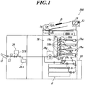
- FIG. 1 is a schematic diagram of an image forming apparatus 100 according to this embodiment.
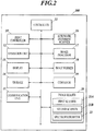
- FIG. 2 is a block diagram showing functional configuration of the image forming apparatus 100.
- the image forming apparatus 100 includes a print controller 10, a controller 11 (information obtaining unit, image data generator, image output controller), an operation unit 12, a display 13, a storage 14, a communication unit 15, an automatic document scanner 16, an image processor 17 (image data generator), an image former 18, a conveyor 19, and an image reader 20.
- the print controller 10 receives PDL (Page Description Language) data from a computer terminal(s) on a communication network, and rasterizes the PDL data to generate image data in a bitmap format.
- PDL Peage Description Language
- the print controller 10 generates the image data for respective colors of C (cyan), M (magenta), Y (yellow), and K (black).
- the controller 11 includes a CPU (Central Processing Unit) and a RAM (Random Access Memory).
- the controller 11 reads a program(s) stored in the storage 14, and controls each component of the image forming apparatus 100 in accordance with the program(s).
- the operation unit 12 includes operation keys and/or a touchscreen provided integrally with the display 13, and outputs operation signals corresponding to operations thereon to the controller 11.
- a user(s) inputs instructions, for example, to set jobs and to change processing details with the operation unit 12.
- the display 13 is a display, such as an LCD, and displays various screens (windows) in accordance with instructions of the controller 11.
- the storage 14 stores programs, files and the like which are readable by the controller 11.
- a storage medium such as a hard disk or a ROM (Read Only Memory), may be used as the storage 14.
- the communication unit 15 communicates with, for example, computers and other image forming apparatuses on a communication network in accordance with instructions of the controller 11.
- the automatic document scanner 16 optically scans a document D which is placed on a document tray and conveyed by a conveyor mechanism, thereby reading the image of the document D by forming, on the light receiving face of a CCD (Charge Coupled Device) sensor, an image of the reflected light from the document D, and generating image data for respective colors of R (red), G (green), and B (blue), and then outputs the data to the image processor 17.
- CCD Charge Coupled Device
- the image processor 17 corrects and performs image processing on the image data input from the automatic document scanner 16 or from the print controller 10, and outputs the data to the image former 18.
- Examples of the image processing include level correction, enlargement/reduction, brightness/contrast adjustment, sharpness adjustment, smoothing, color conversion, tone curve adjustment, and filtering.
- the image former 18 forms an image on paper on the basis of the image data output from the image processor 17.
- the image former 18 includes four sets of an exposure device 18a, a photoconductive drum 18b, a charger 18c, and a developing device 18d, for respective colors of C, M, Y, and K.
- the image former 18 also includes an intermediate transfer belt 18e, secondary transfer rollers 18f, and a fixing device 18g.
- the exposure device 18a includes LDs (Laser Diodes) as light emitting elements.
- the exposure device 18a drives the LDs on the basis of the image data, and emits laser light onto the photoconductive drum 18b charged by the charger 18c, thereby exposing the photoconductive drum 18b.
- the developing device 18d supplies toner onto the photoconductive drum 18b with a charging developing roller, thereby developing an electrostatic latent image formed on the photoconductive drum 18b by the exposure.
- the images thus formed with the respective colors of toner on the four photoconductive drums 18b are transferred to and superposed sequentially on the intermediate transfer belt 18e.
- a color image is formed on the intermediate transfer belt 18e.
- the intermediate transfer belt 18e is an endless belt wound around rollers, and rotates as the rollers rotate.
- the secondary transfer rollers 18f transfer the color image on the intermediate transfer belt 18e onto paper fed from a paper feeding tray t1.
- the fixing device 18g heats and presses the image-formed paper, thereby fixing the color image to the paper.
- the conveyor 19 includes a paper conveyance path equipped with pairs of conveying rollers.
- the conveyor 19 conveys paper in the paper feeding tray t1 to the image former 18, and conveys the paper on which the image has been formed by the image former 18 to the image reader 20, and then ejects the paper to a paper receiving tray t2.
- the image reader 20 reads the image formed on the paper, and outputs the read data to the controller 11.
- the image reader 20 includes a first scanner 21A, a second scanner 21B, and a spectrophotometer 22.
- the first scanner 21A, the second scanner 21B, and the spectrophotometer 22 are provided on the downstream side of the image former 18 along the paper conveyance path so that they can read, before the paper is ejected to the outside (paper receiving tray t2), the image-formed side(s) of the paper.
- the first scanner 21A and the second scanner 21B are provided where the first scanner 21A and the second scanner 21B can read the back side and the front side of the paper being conveyed thereto, respectively.
- the first scanner 21A and the second scanner 21B are each constituted of, for example, a line sensor which has CCDs (Charge Coupled Devices) arranged in line in a direction (paper width direction) which is orthogonal to the paper conveying direction and horizontal to the paper face.
- the first scanner 21A and the second scanner 21B are image readers which read an image(s) formed on paper being conveyed thereto, and output the read data to the controller 11 (shown in FIG. 2 ).
- the spectrophotometer 22 detects spectral reflectance at each wavelength from the image formed on the paper, thereby measuring color(s) of the image.
- the spectrophotometer 22 can recognize color information highly precisely.
- the image forming apparatus 100 allows the user to recognize the replacement timing of each image forming component by outputting an image having a quality predicted to be in the future (future image). More specifically, in order to output the future image, the image forming apparatus 100 performs a data acquisition process to periodically acquire and store noise information on a predetermined image and a future image output process to actually form the future image on paper or display the future image on the display 13.
- FIG. 3 is a flowchart showing the data acquisition process.
- the controller 11 determines whether or not a predetermined timing has arrived (Step S11).
- Examples of the predetermined timing include a timing when a predetermined number of images (e.g. 1,000 images) has been formed since the last data acquisition process, and a timing when the image forming apparatus 100 is turned on. The user can change the predetermined timing as desired.
- a predetermined number of images e.g. 1,000 images
- Step S11 NO
- the controller 11 ends the data acquisition process.
- Step S11 when determining that the predetermined timing has arrived (Step S11: YES), the controller 11 determines whether or not an instruction to form an image for detecting image noise (noise detecting image) has been input (i.e., whether or not an instructing operation for making such an instruction has been performed; the same applies hereinafter) through the operation unit 12 (Step S12).
- an instruction to form an image for detecting image noise noise detecting image
- the noise detecting image is an image having a predetermined gradation (e.g. 50% density), and is set beforehand.
- the controller 11 displays a pop-up image (e.g. pop-up window) on the display 13 for the user to choose whether or not to form the noise detecting image, and in accordance with the user's choosing operation on the pop-up image through the operation unit 12, determines whether or not an instruction to form the noise detecting image has been input.
- a pop-up image e.g. pop-up window
- operation unit 12 e.g. operation unit 12
- a switch which, in accordance with the user's operation on the switch, switches to or from a control mode in which the noise detecting image is automatically formed at the predetermined timing.
- Step S12 NO
- the controller 11 ends the data acquisition process.
- Step S12 when determining that an instruction to form the noise detecting image has been input (Step S12: YES), the controller 11 causes the image former 18 to form the noise detecting image on paper (Step S13).
- the controller 11 causes the image reader 20 to read the noise detecting image formed on the paper and measure luminosity of the image (Step S14).
- the controller 11 causes the spectrophotometer 22 to measure the luminosity (L*) of the noise detecting image on the paper.
- the luminosity is measured at a plurality of dots which are indicated by positions in the main scanning direction (main-scanning-direction positions) and positions in the sub-scanning direction (sub-scanning-direction positions).
- the read/measured data is stored in a data table T1 in the storage 14.
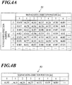
- FIG. 4A shows an example of the data table T1.
- the data table T1 stores the luminosity values (L*) measured at a plurality of dots each indicated by the main-scanning-direction position and the sub-scanning-direction position.
- the controller 11 calculates a luminosity distribution profile in the main scanning direction by averaging the read data, which is stored in the data table T1, in the sub-scanning direction (Step S15).
- the calculated data (luminosity distribution profile) is stored in a data table T2 in the storage 14.
- FIG. 4B shows an example of the data table T2.
- the data table T2 stores the data calculated by averaging the read data, which is stored in the data table T1, in the sub-scanning direction.
- a luminosity distribution profile in the sub-scanning direction may be calculated by averaging the read data, which is stored in the data table T1, in the main scanning direction.
- the controller 11 calculates frequency characteristics of streaks by performing discrete Fourier transform on the calculated luminosity distribution profile (Step S16).
- FIG. 5A shows an example of a graph of the calculated frequency characteristics (F( ⁇ )(t0)).
- FIG. 5B shows an enlarged view of a region R in the graph of FIG. 5A .
- the controller 11 obtains power spectrum values with respect to frequencies [cycles/mm] from the calculated frequency characteristics, associates the obtained data with the date and the number of formed images at the time, stores (saves) the same in a data table T3 in the storage 14 (Step S17), and ends the data acquisition process.
- FIG. 6 shows an example of the data table T3.
- the data table T3 stores, for respective frequencies ( ⁇ ), the power spectrum values (noise information) associated with the date(s) and the number(s) of formed images.
- the data acquisition process forms the noise detecting image at each predetermined timing, and consequently data is obtained and accumulated.
- density may be used instead of the luminosity.
- FIG. 7 is a flowchart showing the future image output process.
- the controller 11 determines whether or not any of counter values of continuous use hours for the respective image forming components, such as the photoconductive drum(s), the charger(s) and the developing device(s), has exceeded its corresponding predetermined value (Step S21).
- the predetermined value is set, for example, at 80% of predetermined maximum hours (life) of use.
- Counter values for the transfer devices (intermediate transfer belt and secondary transfer rollers) and the fixing device may be included.
- Step S21: NO When determining that none of the counter values has exceeded their corresponding predetermined values (Step S21: NO), the controller 11 ends the future image output process.
- Step S21: YES when determining that at least one of the counter values has exceeded its (or their) corresponding predetermined value(s) (Step S21: YES), the controller 11 determines whether or not an instruction to output the future image has been input through the operation unit 12 (Step S22). When determining that an instruction to output the future image has not been input (Step S22: NO), the controller 11 ends the future image output process.
- Step S22 when determining that an instruction to output the future image has been input (Step S22: YES), the controller 11 receives an instruction on a point of time in the future to predict the image quality (prediction point: the number of images to be formed) through the operation unit 12 (Step S23).
- the controller 11 displays an input section (e.g. input window) on the display 13 for the user to enter/input the number of images to be formed, and in accordance with the user's input operation to the input section through the operation unit 12, receives an instruction on a point of time in the future to predict the image quality.
- an input section e.g. input window
- controller 11 performs calculation for prediction of frequency characteristics (Step S24).
- the controller 11 refers to the data table T3 stored in the storage 14 and, for each frequency, plots the power spectrum values with respect to the numbers of formed images, and then obtains an approximation straight line therefrom. Next, the controller 11 obtains a power spectrum value at the specified prediction point using the obtained approximation straight line.
- the power spectrum value at the prediction point is estimated deterioration information on an estimated degree of deterioration of image quality of an image.
- FIG. 8 is an example of a graph in which, about a frequency ( ⁇ 1), the power spectrum values are plotted with respect to the numbers of formed images (images formed and images to be formed).
- the approximation straight line is represented by a solid line.
- the prediction point is set at when 10,000 more images are formed from the present point, and a power spectrum value at the prediction point (estimated deterioration information) is obtained.
- the controller 11 obtains power spectrum values at the prediction point about the other frequencies ( ⁇ 2, ⁇ 3, ).
- the controller 11 receives an instruction on an output method through the operation unit 12 (Step S25).
- the output method is either forming an image on paper with the image former 18 or displaying an image on the display 13.
- the controller 11 displays a choice section (e.g. choice window) on the display 13 for the user to choose an output method, and in accordance with the user's choosing operation on the choice section, determines the output method.
- a choice section e.g. choice window
- the controller 11 reads image data of an image to be output as the future image (Step S26).
- the image to be output by the future image output process may be any image, while it is preferable to always use the same image so as to make comparison easy considering that this future image output process is repeated.
- controller 11 performs frequency filtering on the read image data with the image processor 17 (Step S27).
- the controller 11 performs F( ⁇ )(t1) filtering on the read image data.
- the controller 11 performs F( ⁇ )(t1-t0) filtering on the read image data.
- the controller 11 performs the process which adds only the difference of F( ⁇ )(t1-t0) because the image forming apparatus 100 at this point forms an image which already includes noise of F( ⁇ )(t0).
- the controller 11 uses the filtered image data to output the future image either by displaying the image on the display 13 or by forming the image on paper with the image former 18 (Step S28).
- Step S29 determines whether or not an instruction to continue the future image output process has been input through the operation unit 12 (Step S29).
- Step S29 determines that an instruction to continue the future image output process has been input (Step S29: YES)
- the controller 11 returns to Step S23 to repeat Step S23 and the subsequent steps.
- the controller 11 determines that an instruction to continue the future image output process has been input, the future image will be output at a different prediction point.
- Step S29: NO when determining that an instruction to continue the future image output process has not been input (Step S29: NO), the controller 11 ends the future image output process.
- the future image output process outputs the future image of the user's desired timing (prediction point) on the basis of the data reflecting usage conditions of the image forming apparatus 100. Hence, the user can accurately recognize in advance until when his/her desired image quality will be maintained.
- the controller 11 obtains estimated deterioration information on an estimated degree of deterioration of image quality of an image; with the image processor 17, on the basis of the obtained estimated deterioration information, generates, from arbitrary image data, image data of a future image having a predicted image quality; and causes an output device to output the future image on the basis of the generated image data of the future image.
- the image forming apparatus 100 includes the data tables T1, T2, and T3 (noise information storages in the storage 14) where noise information on a predetermined image is accumulated, wherein the controller 11 obtains the estimated deterioration information on the basis of the noise information accumulated in the data tables T1, T2, and T3.
- the image forming apparatus 100 is configured to accumulate noise information in the data tables T1, T2, and T3, and obtain the estimated deterioration information by using the noise information.
- the noise information is a frequency characteristic(s) of luminosity of the predetermined image in the main scanning direction or the sub-scanning direction.
- the image forming apparatus 100 is configured to use, as the noise information, frequency characteristics of luminosity of the predetermined image in the main scanning direction or the sub-scanning direction.
- the controller 11 generates the image data of the future image by performing, on the arbitrary image data, frequency filtering fit for the estimated deterioration information.
- the image data of the future image can be generated from arbitrary image data.
- the output device is the image former 18 which forms the future image on paper.
- the output device is the display 13 which displays the future image.
- the image forming apparatus 100 includes the image reader 20 which reads the predetermined image, wherein the controller 11 obtains the noise information on the basis of read data obtained by the image reader 20 reading the predetermined image.
- the image forming apparatus 100 is configured to obtain the noise information from the actually read and measured data.
- the controller 11 uses the power spectrum values with respect to the frequencies [cycles/mm] (shown in the data table T3) to obtain the estimated deterioration information.
- the controller 11 may use the luminosity distribution profile (shown in the data table T2) to output the future image. That is, the controller 11 may use the luminosity distribution profile as the noise information.
- the controller 11 refers to the data table T2 stored in the storage 14 and, for each main-scanning-direction position, plots luminosity values with respect to the numbers of formed images, and then obtains an approximation straight line therefrom.
- the controller 11 determines/obtains a luminosity value at a specified prediction point using the obtained approximation straight line.
- FIG. 9 is an example of a graph in which, about a main-scanning-direction position (XI), the luminosity values are plotted with respect to the numbers of formed images (images formed and images to be formed).
- the approximation straight line is represented by a solid line.
- the prediction point is set at when 10,000 more images are formed from the present point, and a luminosity value at the prediction point is obtained as the estimated deterioration information.
- the controller 11 obtains luminosity values at the prediction point about the other main-scanning-direction positions (X2, X3, ).
- the controller 11 performs ⁇ (gamma) correction which adds the luminosity values at the respective main-scanning-direction positions, X1t1, X2t1, ..., to the image data to output.
- the controller 11 performs ⁇ correction which adds the luminosity differences at the respective main-scanning-direction positions, X1t1 - X1t0, X2t1 - X2t0, ..., to the image data to output.
- the data acquisition process is performed. Without the data acquisition process, known experimental data prepared beforehand may be used.
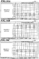
- FIG. 10A, FIG. 10B, and FIG 10C are a data table T11 for chargers, a data table T12 for developing devices, and a data table T13 for photoreceptors, respectively.
- the data tables T11, T12, and T13 (durability information storages) each store, for respective frequencies ( ⁇ ), power spectrum values (durability information) obtained by simulation or the like and associated with the numbers of formed images.
- the data tables T11, T12, and T13 are stored in the storage 14.
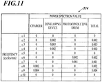
- the total value for each frequency is calculated as shown in FIG. 11 and used to obtain the estimated deterioration information.
Landscapes
- Engineering & Computer Science (AREA)
- Physics & Mathematics (AREA)
- General Physics & Mathematics (AREA)
- Multimedia (AREA)
- Signal Processing (AREA)
- Microelectronics & Electronic Packaging (AREA)
- Health & Medical Sciences (AREA)
- Biomedical Technology (AREA)
- General Health & Medical Sciences (AREA)
- Control Or Security For Electrophotography (AREA)
- Facsimile Image Signal Circuits (AREA)
- Accessory Devices And Overall Control Thereof (AREA)
Abstract
Description
- The present invention relates to an image forming apparatus and a program.
- An electrophotographic image forming apparatus is known to have horizontal and vertical streaks on formed images with long-term use. When such defects occur, components related to image forming (image forming components) are replaced.
- Various technologies to let a user(s) know a replacement timing of each image forming component in advance have been investigated and proposed, such as a technology which allows a user(s) to determine the replacement timing on the basis of a life indicating value(s) calculated from the number of formed images or from a driven distance of a belt, and a technology which obtains a capability value(s) related to the life of a photoreceptor, and predicts the remaining life of the photoreceptor therefrom (for example, disclosed in
JP 2016-145915 A - However, even if the replacement timing of each image forming component is predicted in advance, in actual cases, a user(s) tends to keep using the image forming components until the defects occur in order to reduce downtime of the image forming apparatus.
- Because timings when the defects occur are unpredictable, and also a desired image quality level varies from user to user, it is difficult to predict the replacement timing which is suitable for such cases/use. For example, the technology disclosed in
JP 2016-145915 A - Furthermore, if the defects occur suddenly, the user needs to call a technician, which may lead to the downtime longer than that in the case of replacing an image forming component at its predicted replacement timing.
- Objects of the present invention include providing an image forming apparatus and a program which allow a user(s) to determine the replacement timing of each image forming component suitable for the image quality level that the user(s) desires.
- In order to achieve at least one of the abovementioned objects, according to a first aspect of the present invention, there is provided an image forming apparatus including: an output device; an information obtaining unit which obtains estimated deterioration information on an estimated degree of deterioration of image quality of an image; an image data generator which, based on the estimated deterioration information obtained by the information obtaining unit, generates, from arbitrary image data, image data of a future image having a predicted image quality; and an image output controller which causes the output device to output the future image based on the image data of the future image generated by the image data generator.
- According to a second aspect of the present invention, there is provided a program to cause a computer to function as: an information obtaining unit which obtains estimated deterioration information on an estimated degree of deterioration of image quality of an image; an image data generator which, based on the estimated deterioration information obtained by the information obtaining unit, generates, from arbitrary image data, image data of a future image having a predicted image quality; and an image output controller which causes an output device to output the future image based on the image data of the future image generated by the image data generator.
- The advantages and features provided by one or more embodiments of the present invention will become more fully understood from the detailed description given hereinbelow and the appended drawings which are given by way of illustration only, and thus are not intended as a definition of the limits of the present invention, wherein:
-
FIG. 1 is a schematic diagram of an image forming apparatus; -
FIG. 2 is a block diagram showing functional configuration of the image forming apparatus; -
FIG. 3 is a flowchart showing a data acquisition process; -
FIG. 4A is an example of a data table; -
FIG. 4B is an example of a data table; -
FIG. 5A is an example of a data table; -
FIG. 5B is an example of a data table; -
FIG. 6 is an example of a data table; -
FIG. 7 is a flowchart showing a future image output process; -
FIG. 8 is an example of a graph in which, about a frequency, power spectrum values are plotted with respect to the numbers of formed images; -
FIG. 9 is an example of a graph in which, about a main-scanning-direction position, luminosity values are plotted with respect to the numbers of formed images; -
FIG. 10A is an example of data for explaining a modification; -
FIG. 10B is an example of data for explaining the modification; -
FIG. 10C is an example of data for explaining the modification; and -
FIG. 11 is an example of data for explaining the modification. - Hereinafter, one or more embodiments of the present invention will be described with reference to the drawings. However, the scope of the present invention is not limited to the disclosed embodiments.
- First, configuration of an image forming apparatus according to this embodiment is described.
-
FIG. 1 is a schematic diagram of animage forming apparatus 100 according to this embodiment.FIG. 2 is a block diagram showing functional configuration of theimage forming apparatus 100. - As shown in
FIG. 1 andFIG. 2 , theimage forming apparatus 100 includes aprint controller 10, a controller 11 (information obtaining unit, image data generator, image output controller), anoperation unit 12, adisplay 13, astorage 14, acommunication unit 15, anautomatic document scanner 16, an image processor 17 (image data generator), an image former 18, aconveyor 19, and animage reader 20. - The
print controller 10 receives PDL (Page Description Language) data from a computer terminal(s) on a communication network, and rasterizes the PDL data to generate image data in a bitmap format. - The
print controller 10 generates the image data for respective colors of C (cyan), M (magenta), Y (yellow), and K (black). - The
controller 11 includes a CPU (Central Processing Unit) and a RAM (Random Access Memory). Thecontroller 11 reads a program(s) stored in thestorage 14, and controls each component of theimage forming apparatus 100 in accordance with the program(s). - The
operation unit 12 includes operation keys and/or a touchscreen provided integrally with thedisplay 13, and outputs operation signals corresponding to operations thereon to thecontroller 11. A user(s) inputs instructions, for example, to set jobs and to change processing details with theoperation unit 12. - The
display 13 is a display, such as an LCD, and displays various screens (windows) in accordance with instructions of thecontroller 11. - The
storage 14 stores programs, files and the like which are readable by thecontroller 11. A storage medium, such as a hard disk or a ROM (Read Only Memory), may be used as thestorage 14. - The
communication unit 15 communicates with, for example, computers and other image forming apparatuses on a communication network in accordance with instructions of thecontroller 11. - The automatic document scanner 16 optically scans a document D which is placed on a document tray and conveyed by a conveyor mechanism, thereby reading the image of the document D by forming, on the light receiving face of a CCD (Charge Coupled Device) sensor, an image of the reflected light from the document D, and generating image data for respective colors of R (red), G (green), and B (blue), and then outputs the data to the
image processor 17. - The
image processor 17 corrects and performs image processing on the image data input from theautomatic document scanner 16 or from theprint controller 10, and outputs the data to the image former 18. Examples of the image processing include level correction, enlargement/reduction, brightness/contrast adjustment, sharpness adjustment, smoothing, color conversion, tone curve adjustment, and filtering. - The image former 18 forms an image on paper on the basis of the image data output from the
image processor 17. - As shown in
FIG. 1 , the image former 18 includes four sets of anexposure device 18a, aphotoconductive drum 18b, acharger 18c, and a developingdevice 18d, for respective colors of C, M, Y, and K. The image former 18 also includes anintermediate transfer belt 18e,secondary transfer rollers 18f, and afixing device 18g. - The
exposure device 18a includes LDs (Laser Diodes) as light emitting elements. Theexposure device 18a drives the LDs on the basis of the image data, and emits laser light onto thephotoconductive drum 18b charged by thecharger 18c, thereby exposing thephotoconductive drum 18b. The developingdevice 18d supplies toner onto thephotoconductive drum 18b with a charging developing roller, thereby developing an electrostatic latent image formed on thephotoconductive drum 18b by the exposure. - The images thus formed with the respective colors of toner on the four
photoconductive drums 18b are transferred to and superposed sequentially on theintermediate transfer belt 18e. Thus, a color image is formed on theintermediate transfer belt 18e. Theintermediate transfer belt 18e is an endless belt wound around rollers, and rotates as the rollers rotate. - The
secondary transfer rollers 18f transfer the color image on theintermediate transfer belt 18e onto paper fed from a paper feeding tray t1. The fixingdevice 18g heats and presses the image-formed paper, thereby fixing the color image to the paper. - The
conveyor 19 includes a paper conveyance path equipped with pairs of conveying rollers. Theconveyor 19 conveys paper in the paper feeding tray t1 to the image former 18, and conveys the paper on which the image has been formed by the image former 18 to theimage reader 20, and then ejects the paper to a paper receiving tray t2. - The
image reader 20 reads the image formed on the paper, and outputs the read data to thecontroller 11. - The
image reader 20 includes afirst scanner 21A, asecond scanner 21B, and aspectrophotometer 22. Thefirst scanner 21A, thesecond scanner 21B, and thespectrophotometer 22 are provided on the downstream side of the image former 18 along the paper conveyance path so that they can read, before the paper is ejected to the outside (paper receiving tray t2), the image-formed side(s) of the paper. - The
first scanner 21A and thesecond scanner 21B are provided where thefirst scanner 21A and thesecond scanner 21B can read the back side and the front side of the paper being conveyed thereto, respectively. - The
first scanner 21A and thesecond scanner 21B are each constituted of, for example, a line sensor which has CCDs (Charge Coupled Devices) arranged in line in a direction (paper width direction) which is orthogonal to the paper conveying direction and horizontal to the paper face. Thefirst scanner 21A and thesecond scanner 21B are image readers which read an image(s) formed on paper being conveyed thereto, and output the read data to the controller 11 (shown inFIG. 2 ). - The
spectrophotometer 22 detects spectral reflectance at each wavelength from the image formed on the paper, thereby measuring color(s) of the image. Thespectrophotometer 22 can recognize color information highly precisely. - Next, operation of the
image forming apparatus 100 according to this embodiment is described. - The
image forming apparatus 100 allows the user to recognize the replacement timing of each image forming component by outputting an image having a quality predicted to be in the future (future image). More specifically, in order to output the future image, theimage forming apparatus 100 performs a data acquisition process to periodically acquire and store noise information on a predetermined image and a future image output process to actually form the future image on paper or display the future image on thedisplay 13. -
FIG. 3 is a flowchart showing the data acquisition process. - First, the
controller 11 determines whether or not a predetermined timing has arrived (Step S11). - Examples of the predetermined timing include a timing when a predetermined number of images (e.g. 1,000 images) has been formed since the last data acquisition process, and a timing when the
image forming apparatus 100 is turned on. The user can change the predetermined timing as desired. - When determining that the predetermined timing has not yet arrived (Step S11: NO), the
controller 11 ends the data acquisition process. - On the other hand, when determining that the predetermined timing has arrived (Step S11: YES), the
controller 11 determines whether or not an instruction to form an image for detecting image noise (noise detecting image) has been input (i.e., whether or not an instructing operation for making such an instruction has been performed; the same applies hereinafter) through the operation unit 12 (Step S12). - The noise detecting image is an image having a predetermined gradation (e.g. 50% density), and is set beforehand.
- More specifically, the
controller 11 displays a pop-up image (e.g. pop-up window) on thedisplay 13 for the user to choose whether or not to form the noise detecting image, and in accordance with the user's choosing operation on the pop-up image through theoperation unit 12, determines whether or not an instruction to form the noise detecting image has been input. - There (e.g. operation unit 12) maybe provided a switch which, in accordance with the user's operation on the switch, switches to or from a control mode in which the noise detecting image is automatically formed at the predetermined timing.
- When determining that an instruction to form the noise detecting image has not been input (Step S12: NO), the
controller 11 ends the data acquisition process. - On the other hand, when determining that an instruction to form the noise detecting image has been input (Step S12: YES), the
controller 11 causes the image former 18 to form the noise detecting image on paper (Step S13). - Next, the
controller 11 causes theimage reader 20 to read the noise detecting image formed on the paper and measure luminosity of the image (Step S14). - More specifically, the
controller 11 causes thespectrophotometer 22 to measure the luminosity (L*) of the noise detecting image on the paper. The luminosity is measured at a plurality of dots which are indicated by positions in the main scanning direction (main-scanning-direction positions) and positions in the sub-scanning direction (sub-scanning-direction positions). The read/measured data (luminosity values) is stored in a data table T1 in thestorage 14. -
FIG. 4A shows an example of the data table T1. - As shown in
FIG. 4A , the data table T1 stores the luminosity values (L*) measured at a plurality of dots each indicated by the main-scanning-direction position and the sub-scanning-direction position. - Next, the
controller 11 calculates a luminosity distribution profile in the main scanning direction by averaging the read data, which is stored in the data table T1, in the sub-scanning direction (Step S15). The calculated data (luminosity distribution profile) is stored in a data table T2 in thestorage 14. -
FIG. 4B shows an example of the data table T2. - As shown in
FIG. 4B , the data table T2 stores the data calculated by averaging the read data, which is stored in the data table T1, in the sub-scanning direction. - Additionally or alternatively, a luminosity distribution profile in the sub-scanning direction may be calculated by averaging the read data, which is stored in the data table T1, in the main scanning direction.
- Next, the
controller 11 calculates frequency characteristics of streaks by performing discrete Fourier transform on the calculated luminosity distribution profile (Step S16). -
FIG. 5A shows an example of a graph of the calculated frequency characteristics (F(ω)(t0)).FIG. 5B shows an enlarged view of a region R in the graph ofFIG. 5A . - Next, the
controller 11 obtains power spectrum values with respect to frequencies [cycles/mm] from the calculated frequency characteristics, associates the obtained data with the date and the number of formed images at the time, stores (saves) the same in a data table T3 in the storage 14 (Step S17), and ends the data acquisition process. -
FIG. 6 shows an example of the data table T3. - As shown in
FIG. 6 , the data table T3 stores, for respective frequencies (ω), the power spectrum values (noise information) associated with the date(s) and the number(s) of formed images. - The data acquisition process forms the noise detecting image at each predetermined timing, and consequently data is obtained and accumulated. Instead of the luminosity, density may be used.
-
FIG. 7 is a flowchart showing the future image output process. - First, the
controller 11 determines whether or not any of counter values of continuous use hours for the respective image forming components, such as the photoconductive drum(s), the charger(s) and the developing device(s), has exceeded its corresponding predetermined value (Step S21). - The predetermined value is set, for example, at 80% of predetermined maximum hours (life) of use.
- Counter values for the transfer devices (intermediate transfer belt and secondary transfer rollers) and the fixing device may be included.
- When determining that none of the counter values has exceeded their corresponding predetermined values (Step S21: NO), the
controller 11 ends the future image output process. - On the other hand, when determining that at least one of the counter values has exceeded its (or their) corresponding predetermined value(s) (Step S21: YES), the
controller 11 determines whether or not an instruction to output the future image has been input through the operation unit 12 (Step S22). When determining that an instruction to output the future image has not been input (Step S22: NO), thecontroller 11 ends the future image output process. - On the other hand, when determining that an instruction to output the future image has been input (Step S22: YES), the
controller 11 receives an instruction on a point of time in the future to predict the image quality (prediction point: the number of images to be formed) through the operation unit 12 (Step S23). - More specifically, the
controller 11 displays an input section (e.g. input window) on thedisplay 13 for the user to enter/input the number of images to be formed, and in accordance with the user's input operation to the input section through theoperation unit 12, receives an instruction on a point of time in the future to predict the image quality. - Next, the
controller 11 performs calculation for prediction of frequency characteristics (Step S24). - More specifically, first, the
controller 11 refers to the data table T3 stored in thestorage 14 and, for each frequency, plots the power spectrum values with respect to the numbers of formed images, and then obtains an approximation straight line therefrom. Next, thecontroller 11 obtains a power spectrum value at the specified prediction point using the obtained approximation straight line. The power spectrum value at the prediction point is estimated deterioration information on an estimated degree of deterioration of image quality of an image. -
FIG. 8 is an example of a graph in which, about a frequency (ω1), the power spectrum values are plotted with respect to the numbers of formed images (images formed and images to be formed). The approximation straight line is represented by a solid line. - In the case shown in
FIG. 8 , the prediction point is set at when 10,000 more images are formed from the present point, and a power spectrum value at the prediction point (estimated deterioration information) is obtained. - Similarly, the
controller 11 obtains power spectrum values at the prediction point about the other frequencies (ω2, ω3, ...). - Next, the
controller 11 receives an instruction on an output method through the operation unit 12 (Step S25). - The output method is either forming an image on paper with the image former 18 or displaying an image on the
display 13. Thecontroller 11 displays a choice section (e.g. choice window) on thedisplay 13 for the user to choose an output method, and in accordance with the user's choosing operation on the choice section, determines the output method. - Next, the
controller 11 reads image data of an image to be output as the future image (Step S26). The image to be output by the future image output process may be any image, while it is preferable to always use the same image so as to make comparison easy considering that this future image output process is repeated. - Next, the
controller 11 performs frequency filtering on the read image data with the image processor 17 (Step S27). - More specifically, to display an image on the
display 13, thecontroller 11 performs F(ω)(t1) filtering on the read image data. - Meanwhile, to form an image on paper, the
controller 11 performs F(ω)(t1-t0) filtering on the read image data. In this case, where an image is formed on paper, thecontroller 11 performs the process which adds only the difference of F(ω)(t1-t0) because theimage forming apparatus 100 at this point forms an image which already includes noise of F(ω)(t0). - Using the filtered image data, the
controller 11 outputs the future image either by displaying the image on thedisplay 13 or by forming the image on paper with the image former 18 (Step S28). - Next, the
controller 11 determines whether or not an instruction to continue the future image output process has been input through the operation unit 12 (Step S29). When determining that an instruction to continue the future image output process has been input (Step S29: YES), thecontroller 11 returns to Step S23 to repeat Step S23 and the subsequent steps. - That is, when the
controller 11 determines that an instruction to continue the future image output process has been input, the future image will be output at a different prediction point. - On the other hand, when determining that an instruction to continue the future image output process has not been input (Step S29: NO), the
controller 11 ends the future image output process. - The future image output process outputs the future image of the user's desired timing (prediction point) on the basis of the data reflecting usage conditions of the
image forming apparatus 100. Hence, the user can accurately recognize in advance until when his/her desired image quality will be maintained. - As described above, according to this embodiment, the
controller 11 obtains estimated deterioration information on an estimated degree of deterioration of image quality of an image; with theimage processor 17, on the basis of the obtained estimated deterioration information, generates, from arbitrary image data, image data of a future image having a predicted image quality; and causes an output device to output the future image on the basis of the generated image data of the future image. - This allows the user to check a future image quality with the output future image and determine the replacement timing of each image forming component in advance, the replacement timing being suitable for the user's desired image quality.
- Furthermore, according to this embodiment, the
image forming apparatus 100 includes the data tables T1, T2, and T3 (noise information storages in the storage 14) where noise information on a predetermined image is accumulated, wherein thecontroller 11 obtains the estimated deterioration information on the basis of the noise information accumulated in the data tables T1, T2, and T3. - Thus, the
image forming apparatus 100 is configured to accumulate noise information in the data tables T1, T2, and T3, and obtain the estimated deterioration information by using the noise information. - Furthermore, according to this embodiment, the noise information is a frequency characteristic(s) of luminosity of the predetermined image in the main scanning direction or the sub-scanning direction.
- Thus, the
image forming apparatus 100 is configured to use, as the noise information, frequency characteristics of luminosity of the predetermined image in the main scanning direction or the sub-scanning direction. - Furthermore, according to this embodiment, the
controller 11 generates the image data of the future image by performing, on the arbitrary image data, frequency filtering fit for the estimated deterioration information. - Thus, the image data of the future image can be generated from arbitrary image data.
- Furthermore, according to this embodiment, the output device is the image former 18 which forms the future image on paper.
- This allows the user to check the future image formed on paper.
- Furthermore, according to this embodiment, the output device is the
display 13 which displays the future image. - This allows the user to check the future image displayed on the
display 13. - Furthermore, according to this embodiment, the
image forming apparatus 100 includes theimage reader 20 which reads the predetermined image, wherein thecontroller 11 obtains the noise information on the basis of read data obtained by theimage reader 20 reading the predetermined image. - Thus, the
image forming apparatus 100 is configured to obtain the noise information from the actually read and measured data. - In the above embodiment, the
controller 11 uses the power spectrum values with respect to the frequencies [cycles/mm] (shown in the data table T3) to obtain the estimated deterioration information. Instead of the frequency characteristics, thecontroller 11 may use the luminosity distribution profile (shown in the data table T2) to output the future image. That is, thecontroller 11 may use the luminosity distribution profile as the noise information. - In this case, the
controller 11 refers to the data table T2 stored in thestorage 14 and, for each main-scanning-direction position, plots luminosity values with respect to the numbers of formed images, and then obtains an approximation straight line therefrom. Thecontroller 11 determines/obtains a luminosity value at a specified prediction point using the obtained approximation straight line. -
FIG. 9 is an example of a graph in which, about a main-scanning-direction position (XI), the luminosity values are plotted with respect to the numbers of formed images (images formed and images to be formed). The approximation straight line is represented by a solid line. - In the case shown in
FIG. 9 , the prediction point is set at when 10,000 more images are formed from the present point, and a luminosity value at the prediction point is obtained as the estimated deterioration information. - Similarly, the
controller 11 obtains luminosity values at the prediction point about the other main-scanning-direction positions (X2, X3, ...). - To display an image on the
display 13, thecontroller 11 performs γ (gamma) correction which adds the luminosity values at the respective main-scanning-direction positions, X1t1, X2t1, ..., to the image data to output. - Meanwhile, to form an image on paper, the
controller 11 performs γ correction which adds the luminosity differences at the respective main-scanning-direction positions, X1t1 - X1t0, X2t1 - X2t0, ..., to the image data to output. - Thus, the future image is output as with the above embodiment.
- In the above embodiment, the data acquisition process is performed. Without the data acquisition process, known experimental data prepared beforehand may be used.
- For example,
FIG. 10A, FIG. 10B, and FIG 10C are a data table T11 for chargers, a data table T12 for developing devices, and a data table T13 for photoreceptors, respectively. The data tables T11, T12, and T13 (durability information storages) each store, for respective frequencies (ω), power spectrum values (durability information) obtained by simulation or the like and associated with the numbers of formed images. The data tables T11, T12, and T13 are stored in thestorage 14. - For example, to estimate the frequency characteristics with the
charger 18c having 20,000 as the number of formed images, the developingdevice 18d having 30,000 as the number of formed images, and thephotoconductive drum 18b having 10,000 as the number of formed images, the total value for each frequency is calculated as shown inFIG. 11 and used to obtain the estimated deterioration information. - Embodiments to which the present invention is applicable are not limited to the abovementioned embodiment(s) or modifications, and can be appropriately modified without departing from the scope of the present invention.
- Although some embodiments of the present invention have been described and illustrated in detail, the disclosed embodiments are made for purposes of illustration and example only and not limitation. The scope of the present invention should be interpreted by terms of the appended claims.
Claims (11)
- An image forming apparatus (100) comprising:an output device (13, 18);an information obtaining unit (11) which obtains estimated deterioration information on an estimated degree of deterioration of image quality of an image;an image data generator (11, 17) which, based on the estimated deterioration information obtained by the information obtaining unit (11), generates, from arbitrary image data, image data of a future image having a predicted image quality; andan image output controller (11) which causes the output device (13, 18) to output the future image based on the image data of the future image generated by the image data generator (11, 17).
- The image forming apparatus (100) according to claim 1, comprising a noise information storage (14, T1, T2, T3) where noise information on a predetermined image is accumulated, wherein
the information obtaining unit (11) obtains the estimated deterioration information based on the noise information accumulated in the noise information storage (14, T1, T2, T3). - The image forming apparatus (100) according to claim 2, wherein the noise information is a frequency characteristic of luminosity of the predetermined image in a main scanning direction or a sub-scanning direction.
- The image forming apparatus (100) according to claim 3, wherein the image data generator (11, 17) generates the image data of the future image by performing, on the arbitrary image data, frequency filtering fit for the estimated deterioration information.
- The image forming apparatus (100) according to claim 2, wherein the noise information is a luminosity distribution profile of the predetermined image in a main scanning direction.
- The image forming apparatus (100) according to claim 5, wherein the image data generator (11, 17) generates the image data of the future image by performing, on the arbitrary image data, gamma correction fit for a luminosity value as the estimated deterioration information.
- The image forming apparatus (100) according to any one of claims 1 to 6, wherein the output device is an image former (18) which forms the future image on paper.
- The image forming apparatus (100) according to any one of claims 1 to 6, wherein the output device is a display (13) which displays the future image.
- The image forming apparatus (100) according to any one of claims 2 to 6, comprising an image reader (20) which reads the predetermined image, wherein
the information obtaining unit (11) obtains the noise information based on read data obtained by the image reader (20) reading the predetermined image. - The image forming apparatus (100) according to claim 1, comprising a durability information storage (14, T11, T12, T13) where durability information on a component related to image forming is stored, wherein
the information obtaining unit (11) obtains the estimated deterioration information based on the durability information stored in the durability information storage (14, T11, T12, T13). - A program to cause a computer (11) to function as:an information obtaining unit (11) which obtains estimated deterioration information on an estimated degree of deterioration of image quality of an image;an image data generator (11, 17) which, based on the estimated deterioration information obtained by the information obtaining unit (11), generates, from arbitrary image data, image data of a future image having a predicted image quality; andan image output controller (11) which causes an output device (13, 18) to output the future image based on the image data of the future image generated by the image data generator (11, 17).
Applications Claiming Priority (1)
| Application Number | Priority Date | Filing Date | Title |
|---|---|---|---|
| JP2018099314A JP2019203997A (en) | 2018-05-24 | 2018-05-24 | Image forming apparatus and program |
Publications (2)
| Publication Number | Publication Date |
|---|---|
| EP3582024A1 true EP3582024A1 (en) | 2019-12-18 |
| EP3582024B1 EP3582024B1 (en) | 2020-11-11 |
Family
ID=66630247
Family Applications (1)
| Application Number | Title | Priority Date | Filing Date |
|---|---|---|---|
| EP19175945.5A Not-in-force EP3582024B1 (en) | 2018-05-24 | 2019-05-22 | Image forming apparatus and program |
Country Status (4)
| Country | Link |
|---|---|
| US (1) | US20190364156A1 (en) |
| EP (1) | EP3582024B1 (en) |
| JP (1) | JP2019203997A (en) |
| CN (1) | CN110531592A (en) |
Families Citing this family (1)
| Publication number | Priority date | Publication date | Assignee | Title |
|---|---|---|---|---|
| JP7720933B2 (en) | 2024-01-19 | 2025-08-08 | キヤノン株式会社 | Diagnostic device, control method thereof, program, and image forming device |
Citations (2)
| Publication number | Priority date | Publication date | Assignee | Title |
|---|---|---|---|---|
| US20050117928A1 (en) * | 2003-11-27 | 2005-06-02 | Makoto Hino | Image forming apparatus, image forming system, image forming condition adjusting method, computer program carrying out the image forming condition adjusting method, and recording medium storing the program |
| JP2016145915A (en) | 2015-02-06 | 2016-08-12 | キヤノン株式会社 | Image forming apparatus |
Family Cites Families (13)
| Publication number | Priority date | Publication date | Assignee | Title |
|---|---|---|---|---|
| JP2000221846A (en) * | 1999-02-03 | 2000-08-11 | Fujitsu Ltd | Printing equipment |
| JPWO2002044974A1 (en) * | 2000-11-30 | 2004-04-02 | 松下電器産業株式会社 | Information processing apparatus and information display method |
| JP4538845B2 (en) * | 2004-04-21 | 2010-09-08 | 富士ゼロックス株式会社 | FAILURE DIAGNOSIS METHOD, FAILURE DIAGNOSIS DEVICE, IMAGE FORMING DEVICE, PROGRAM, AND STORAGE MEDIUM |
| JP4933888B2 (en) * | 2006-09-19 | 2012-05-16 | 株式会社リコー | Image forming apparatus and image forming method |
| US7787786B2 (en) * | 2006-12-29 | 2010-08-31 | Kabushiki Kaisha Toshiba | Image forming apparatus and image adjusting method involving fluctuation-information acquiring unit and control unit that forms gradation pattern |
| JP2008304755A (en) * | 2007-06-08 | 2008-12-18 | Fuji Xerox Co Ltd | Verifying method and verifying system |
| US8849132B2 (en) * | 2011-03-31 | 2014-09-30 | Eastman Kodak Company | Compensating for periodic nonuniformity in electrophotographic printer |
| JP5825863B2 (en) * | 2011-06-07 | 2015-12-02 | キヤノン株式会社 | Image processing apparatus and control method thereof |
| JP5971010B2 (en) * | 2012-07-30 | 2016-08-17 | 沖電気工業株式会社 | Moving picture decoding apparatus and program, and moving picture encoding system |
| JP2014119845A (en) * | 2012-12-14 | 2014-06-30 | Seiko Epson Corp | Print control device and print control method |
| JP6307961B2 (en) * | 2014-03-18 | 2018-04-11 | コニカミノルタ株式会社 | Image forming apparatus |
| JP6631308B2 (en) * | 2016-02-22 | 2020-01-15 | コニカミノルタ株式会社 | Image forming device |
| GB2559398A (en) * | 2017-02-04 | 2018-08-08 | PQ Solutions Ltd | Controlled and verifiable information destruction |
-
2018
- 2018-05-24 JP JP2018099314A patent/JP2019203997A/en active Pending
-
2019
- 2019-05-15 US US16/413,011 patent/US20190364156A1/en not_active Abandoned
- 2019-05-21 CN CN201910420575.1A patent/CN110531592A/en active Pending
- 2019-05-22 EP EP19175945.5A patent/EP3582024B1/en not_active Not-in-force
Patent Citations (2)
| Publication number | Priority date | Publication date | Assignee | Title |
|---|---|---|---|---|
| US20050117928A1 (en) * | 2003-11-27 | 2005-06-02 | Makoto Hino | Image forming apparatus, image forming system, image forming condition adjusting method, computer program carrying out the image forming condition adjusting method, and recording medium storing the program |
| JP2016145915A (en) | 2015-02-06 | 2016-08-12 | キヤノン株式会社 | Image forming apparatus |
Also Published As
| Publication number | Publication date |
|---|---|
| US20190364156A1 (en) | 2019-11-28 |
| EP3582024B1 (en) | 2020-11-11 |
| CN110531592A (en) | 2019-12-03 |
| JP2019203997A (en) | 2019-11-28 |
Similar Documents
| Publication | Publication Date | Title |
|---|---|---|
| US8797600B2 (en) | Image forming apparatus and gradation correction method with density unevenness detection | |
| US20130301083A1 (en) | Image inspection device, image inspection system, image inspection method, and computer program | |
| JP6070636B2 (en) | Image forming apparatus | |
| RU2654002C2 (en) | Apparatus for image formation which generates a conversion condition of a measuring unit and control method of image forming apparatus | |
| JP2017037148A (en) | Image forming apparatus | |
| EP2299686A2 (en) | Image Forming Apparatus | |
| JP7630923B2 (en) | Colorimeter | |
| EP3582024B1 (en) | Image forming apparatus and program | |
| US9933740B2 (en) | Image forming apparatus that generates conversion condition based on measurement result and first coefficient, and where chromatic color image is formed after predetermined number of monochrome images, generates conversion condition based on new measurement result and second coefficient | |
| JP2016018129A (en) | Image forming apparatus | |
| EP2866095A1 (en) | Image forming apparatus | |
| EP2785041B1 (en) | Image processing apparatus, image forming apparatus, image processing method, and program | |
| US8843007B2 (en) | Image forming apparatus with toner deposit control and paper interval control | |
| US9354541B2 (en) | Image forming apparatus and exposure position adjusting method | |
| JP6051747B2 (en) | Image forming apparatus | |
| JP2016156929A (en) | Image forming apparatus and image forming apparatus control method | |
| JP2018010061A (en) | Image formation apparatus and image density control method | |
| JP6965550B2 (en) | Image forming device, image forming system, correction control method and correction control program | |
| US20120120419A1 (en) | Image forming apparatus and tone correction method of image forming apparatus | |
| US11681252B2 (en) | Image forming apparatus | |
| US9122211B2 (en) | Image forming apparatus with function to measure gloss level | |
| JP2019186809A (en) | Image formation device and program | |
| JP2007036411A (en) | Image processing apparatus and image processing method | |
| JP2019105463A (en) | Spectrophotometer and image forming device | |
| JP2019209524A (en) | Image formation device |
Legal Events
| Date | Code | Title | Description |
|---|---|---|---|
| PUAI | Public reference made under article 153(3) epc to a published international application that has entered the european phase |
Free format text: ORIGINAL CODE: 0009012 |
|
| STAA | Information on the status of an ep patent application or granted ep patent |
Free format text: STATUS: THE APPLICATION HAS BEEN PUBLISHED |
|
| AK | Designated contracting states |
Kind code of ref document: A1 Designated state(s): AL AT BE BG CH CY CZ DE DK EE ES FI FR GB GR HR HU IE IS IT LI LT LU LV MC MK MT NL NO PL PT RO RS SE SI SK SM TR |
|
| AX | Request for extension of the european patent |
Extension state: BA ME |
|
| STAA | Information on the status of an ep patent application or granted ep patent |
Free format text: STATUS: REQUEST FOR EXAMINATION WAS MADE |
|
| 17P | Request for examination filed |
Effective date: 20200506 |
|
| RBV | Designated contracting states (corrected) |
Designated state(s): AL AT BE BG CH CY CZ DE DK EE ES FI FR GB GR HR HU IE IS IT LI LT LU LV MC MK MT NL NO PL PT RO RS SE SI SK SM TR |
|
| GRAP | Despatch of communication of intention to grant a patent |
Free format text: ORIGINAL CODE: EPIDOSNIGR1 |
|
| STAA | Information on the status of an ep patent application or granted ep patent |
Free format text: STATUS: GRANT OF PATENT IS INTENDED |
|
| INTG | Intention to grant announced |
Effective date: 20200612 |
|
| GRAS | Grant fee paid |
Free format text: ORIGINAL CODE: EPIDOSNIGR3 |
|
| GRAA | (expected) grant |
Free format text: ORIGINAL CODE: 0009210 |
|
| STAA | Information on the status of an ep patent application or granted ep patent |
Free format text: STATUS: THE PATENT HAS BEEN GRANTED |
|
| AK | Designated contracting states |
Kind code of ref document: B1 Designated state(s): AL AT BE BG CH CY CZ DE DK EE ES FI FR GB GR HR HU IE IS IT LI LT LU LV MC MK MT NL NO PL PT RO RS SE SI SK SM TR |
|
| REG | Reference to a national code |
Ref country code: GB Ref legal event code: FG4D |
|
| REG | Reference to a national code |
Ref country code: CH Ref legal event code: EP |
|
| REG | Reference to a national code |
Ref country code: AT Ref legal event code: REF Ref document number: 1334073 Country of ref document: AT Kind code of ref document: T Effective date: 20201115 |
|
| REG | Reference to a national code |
Ref country code: DE Ref legal event code: R096 Ref document number: 602019001266 Country of ref document: DE |
|
| REG | Reference to a national code |
Ref country code: IE Ref legal event code: FG4D |
|
| REG | Reference to a national code |
Ref country code: NL Ref legal event code: MP Effective date: 20201111 |
|
| REG | Reference to a national code |
Ref country code: AT Ref legal event code: MK05 Ref document number: 1334073 Country of ref document: AT Kind code of ref document: T Effective date: 20201111 |
|
| PG25 | Lapsed in a contracting state [announced via postgrant information from national office to epo] |
Ref country code: FI Free format text: LAPSE BECAUSE OF FAILURE TO SUBMIT A TRANSLATION OF THE DESCRIPTION OR TO PAY THE FEE WITHIN THE PRESCRIBED TIME-LIMIT Effective date: 20201111 Ref country code: RS Free format text: LAPSE BECAUSE OF FAILURE TO SUBMIT A TRANSLATION OF THE DESCRIPTION OR TO PAY THE FEE WITHIN THE PRESCRIBED TIME-LIMIT Effective date: 20201111 Ref country code: PT Free format text: LAPSE BECAUSE OF FAILURE TO SUBMIT A TRANSLATION OF THE DESCRIPTION OR TO PAY THE FEE WITHIN THE PRESCRIBED TIME-LIMIT Effective date: 20210311 Ref country code: NO Free format text: LAPSE BECAUSE OF FAILURE TO SUBMIT A TRANSLATION OF THE DESCRIPTION OR TO PAY THE FEE WITHIN THE PRESCRIBED TIME-LIMIT Effective date: 20210211 Ref country code: GR Free format text: LAPSE BECAUSE OF FAILURE TO SUBMIT A TRANSLATION OF THE DESCRIPTION OR TO PAY THE FEE WITHIN THE PRESCRIBED TIME-LIMIT Effective date: 20210212 |
|
| PG25 | Lapsed in a contracting state [announced via postgrant information from national office to epo] |
Ref country code: SE Free format text: LAPSE BECAUSE OF FAILURE TO SUBMIT A TRANSLATION OF THE DESCRIPTION OR TO PAY THE FEE WITHIN THE PRESCRIBED TIME-LIMIT Effective date: 20201111 Ref country code: PL Free format text: LAPSE BECAUSE OF FAILURE TO SUBMIT A TRANSLATION OF THE DESCRIPTION OR TO PAY THE FEE WITHIN THE PRESCRIBED TIME-LIMIT Effective date: 20201111 Ref country code: LV Free format text: LAPSE BECAUSE OF FAILURE TO SUBMIT A TRANSLATION OF THE DESCRIPTION OR TO PAY THE FEE WITHIN THE PRESCRIBED TIME-LIMIT Effective date: 20201111 Ref country code: IS Free format text: LAPSE BECAUSE OF FAILURE TO SUBMIT A TRANSLATION OF THE DESCRIPTION OR TO PAY THE FEE WITHIN THE PRESCRIBED TIME-LIMIT Effective date: 20210311 Ref country code: BG Free format text: LAPSE BECAUSE OF FAILURE TO SUBMIT A TRANSLATION OF THE DESCRIPTION OR TO PAY THE FEE WITHIN THE PRESCRIBED TIME-LIMIT Effective date: 20210211 Ref country code: AT Free format text: LAPSE BECAUSE OF FAILURE TO SUBMIT A TRANSLATION OF THE DESCRIPTION OR TO PAY THE FEE WITHIN THE PRESCRIBED TIME-LIMIT Effective date: 20201111 |
|
| REG | Reference to a national code |
Ref country code: LT Ref legal event code: MG9D |
|
| PG25 | Lapsed in a contracting state [announced via postgrant information from national office to epo] |
Ref country code: HR Free format text: LAPSE BECAUSE OF FAILURE TO SUBMIT A TRANSLATION OF THE DESCRIPTION OR TO PAY THE FEE WITHIN THE PRESCRIBED TIME-LIMIT Effective date: 20201111 |
|
| PG25 | Lapsed in a contracting state [announced via postgrant information from national office to epo] |
Ref country code: LT Free format text: LAPSE BECAUSE OF FAILURE TO SUBMIT A TRANSLATION OF THE DESCRIPTION OR TO PAY THE FEE WITHIN THE PRESCRIBED TIME-LIMIT Effective date: 20201111 Ref country code: RO Free format text: LAPSE BECAUSE OF FAILURE TO SUBMIT A TRANSLATION OF THE DESCRIPTION OR TO PAY THE FEE WITHIN THE PRESCRIBED TIME-LIMIT Effective date: 20201111 Ref country code: CZ Free format text: LAPSE BECAUSE OF FAILURE TO SUBMIT A TRANSLATION OF THE DESCRIPTION OR TO PAY THE FEE WITHIN THE PRESCRIBED TIME-LIMIT Effective date: 20201111 Ref country code: EE Free format text: LAPSE BECAUSE OF FAILURE TO SUBMIT A TRANSLATION OF THE DESCRIPTION OR TO PAY THE FEE WITHIN THE PRESCRIBED TIME-LIMIT Effective date: 20201111 Ref country code: SK Free format text: LAPSE BECAUSE OF FAILURE TO SUBMIT A TRANSLATION OF THE DESCRIPTION OR TO PAY THE FEE WITHIN THE PRESCRIBED TIME-LIMIT Effective date: 20201111 Ref country code: SM Free format text: LAPSE BECAUSE OF FAILURE TO SUBMIT A TRANSLATION OF THE DESCRIPTION OR TO PAY THE FEE WITHIN THE PRESCRIBED TIME-LIMIT Effective date: 20201111 |
|
| REG | Reference to a national code |
Ref country code: DE Ref legal event code: R097 Ref document number: 602019001266 Country of ref document: DE |
|
| PG25 | Lapsed in a contracting state [announced via postgrant information from national office to epo] |
Ref country code: DK Free format text: LAPSE BECAUSE OF FAILURE TO SUBMIT A TRANSLATION OF THE DESCRIPTION OR TO PAY THE FEE WITHIN THE PRESCRIBED TIME-LIMIT Effective date: 20201111 |
|
| PLBE | No opposition filed within time limit |
Free format text: ORIGINAL CODE: 0009261 |
|
| STAA | Information on the status of an ep patent application or granted ep patent |
Free format text: STATUS: NO OPPOSITION FILED WITHIN TIME LIMIT |
|
| 26N | No opposition filed |
Effective date: 20210812 |
|
| PG25 | Lapsed in a contracting state [announced via postgrant information from national office to epo] |
Ref country code: NL Free format text: LAPSE BECAUSE OF FAILURE TO SUBMIT A TRANSLATION OF THE DESCRIPTION OR TO PAY THE FEE WITHIN THE PRESCRIBED TIME-LIMIT Effective date: 20201111 Ref country code: AL Free format text: LAPSE BECAUSE OF FAILURE TO SUBMIT A TRANSLATION OF THE DESCRIPTION OR TO PAY THE FEE WITHIN THE PRESCRIBED TIME-LIMIT Effective date: 20201111 Ref country code: IT Free format text: LAPSE BECAUSE OF FAILURE TO SUBMIT A TRANSLATION OF THE DESCRIPTION OR TO PAY THE FEE WITHIN THE PRESCRIBED TIME-LIMIT Effective date: 20201111 |
|
| PG25 | Lapsed in a contracting state [announced via postgrant information from national office to epo] |
Ref country code: SI Free format text: LAPSE BECAUSE OF FAILURE TO SUBMIT A TRANSLATION OF THE DESCRIPTION OR TO PAY THE FEE WITHIN THE PRESCRIBED TIME-LIMIT Effective date: 20201111 |
|
| REG | Reference to a national code |
Ref country code: DE Ref legal event code: R119 Ref document number: 602019001266 Country of ref document: DE |
|
| PG25 | Lapsed in a contracting state [announced via postgrant information from national office to epo] |
Ref country code: ES Free format text: LAPSE BECAUSE OF FAILURE TO SUBMIT A TRANSLATION OF THE DESCRIPTION OR TO PAY THE FEE WITHIN THE PRESCRIBED TIME-LIMIT Effective date: 20201111 Ref country code: LU Free format text: LAPSE BECAUSE OF NON-PAYMENT OF DUE FEES Effective date: 20210522 Ref country code: MC Free format text: LAPSE BECAUSE OF FAILURE TO SUBMIT A TRANSLATION OF THE DESCRIPTION OR TO PAY THE FEE WITHIN THE PRESCRIBED TIME-LIMIT Effective date: 20201111 |
|
| REG | Reference to a national code |
Ref country code: BE Ref legal event code: MM Effective date: 20210531 |
|
| PG25 | Lapsed in a contracting state [announced via postgrant information from national office to epo] |
Ref country code: IE Free format text: LAPSE BECAUSE OF NON-PAYMENT OF DUE FEES Effective date: 20210522 Ref country code: DE Free format text: LAPSE BECAUSE OF NON-PAYMENT OF DUE FEES Effective date: 20211201 |
|
| PG25 | Lapsed in a contracting state [announced via postgrant information from national office to epo] |
Ref country code: IS Free format text: LAPSE BECAUSE OF FAILURE TO SUBMIT A TRANSLATION OF THE DESCRIPTION OR TO PAY THE FEE WITHIN THE PRESCRIBED TIME-LIMIT Effective date: 20210311 Ref country code: FR Free format text: LAPSE BECAUSE OF NON-PAYMENT OF DUE FEES Effective date: 20210531 |
|
| PG25 | Lapsed in a contracting state [announced via postgrant information from national office to epo] |
Ref country code: BE Free format text: LAPSE BECAUSE OF NON-PAYMENT OF DUE FEES Effective date: 20210531 |
|
| REG | Reference to a national code |
Ref country code: CH Ref legal event code: PL |
|
| PG25 | Lapsed in a contracting state [announced via postgrant information from national office to epo] |
Ref country code: LI Free format text: LAPSE BECAUSE OF NON-PAYMENT OF DUE FEES Effective date: 20220531 Ref country code: CH Free format text: LAPSE BECAUSE OF NON-PAYMENT OF DUE FEES Effective date: 20220531 |
|
| PG25 | Lapsed in a contracting state [announced via postgrant information from national office to epo] |
Ref country code: CY Free format text: LAPSE BECAUSE OF FAILURE TO SUBMIT A TRANSLATION OF THE DESCRIPTION OR TO PAY THE FEE WITHIN THE PRESCRIBED TIME-LIMIT Effective date: 20201111 |
|
| PG25 | Lapsed in a contracting state [announced via postgrant information from national office to epo] |
Ref country code: HU Free format text: LAPSE BECAUSE OF FAILURE TO SUBMIT A TRANSLATION OF THE DESCRIPTION OR TO PAY THE FEE WITHIN THE PRESCRIBED TIME-LIMIT; INVALID AB INITIO Effective date: 20190522 |
|
| GBPC | Gb: european patent ceased through non-payment of renewal fee |
Effective date: 20230522 |
|
| PG25 | Lapsed in a contracting state [announced via postgrant information from national office to epo] |
Ref country code: MK Free format text: LAPSE BECAUSE OF FAILURE TO SUBMIT A TRANSLATION OF THE DESCRIPTION OR TO PAY THE FEE WITHIN THE PRESCRIBED TIME-LIMIT Effective date: 20201111 Ref country code: GB Free format text: LAPSE BECAUSE OF NON-PAYMENT OF DUE FEES Effective date: 20230522 |
|
| PG25 | Lapsed in a contracting state [announced via postgrant information from national office to epo] |
Ref country code: TR Free format text: LAPSE BECAUSE OF FAILURE TO SUBMIT A TRANSLATION OF THE DESCRIPTION OR TO PAY THE FEE WITHIN THE PRESCRIBED TIME-LIMIT Effective date: 20201111 |
|
| PG25 | Lapsed in a contracting state [announced via postgrant information from national office to epo] |
Ref country code: MT Free format text: LAPSE BECAUSE OF FAILURE TO SUBMIT A TRANSLATION OF THE DESCRIPTION OR TO PAY THE FEE WITHIN THE PRESCRIBED TIME-LIMIT Effective date: 20201111 |