EP3581747A1 - Überwachungseinrichtung - Google Patents
Überwachungseinrichtung Download PDFInfo
- Publication number
- EP3581747A1 EP3581747A1 EP19179115.1A EP19179115A EP3581747A1 EP 3581747 A1 EP3581747 A1 EP 3581747A1 EP 19179115 A EP19179115 A EP 19179115A EP 3581747 A1 EP3581747 A1 EP 3581747A1
- Authority
- EP
- European Patent Office
- Prior art keywords
- revolving door
- distance
- door
- monitoring device
- wing
- Prior art date
- Legal status (The legal status is an assumption and is not a legal conclusion. Google has not performed a legal analysis and makes no representation as to the accuracy of the status listed.)
- Granted
Links
Images

Classifications
-
- E—FIXED CONSTRUCTIONS
- E05—LOCKS; KEYS; WINDOW OR DOOR FITTINGS; SAFES
- E05F—DEVICES FOR MOVING WINGS INTO OPEN OR CLOSED POSITION; CHECKS FOR WINGS; WING FITTINGS NOT OTHERWISE PROVIDED FOR, CONCERNED WITH THE FUNCTIONING OF THE WING
- E05F15/00—Power-operated mechanisms for wings
- E05F15/40—Safety devices, e.g. detection of obstructions or end positions
- E05F15/42—Detection using safety edges
- E05F15/43—Detection using safety edges responsive to disruption of energy beams, e.g. light or sound
-
- E—FIXED CONSTRUCTIONS
- E06—DOORS, WINDOWS, SHUTTERS, OR ROLLER BLINDS IN GENERAL; LADDERS
- E06B—FIXED OR MOVABLE CLOSURES FOR OPENINGS IN BUILDINGS, VEHICLES, FENCES OR LIKE ENCLOSURES IN GENERAL, e.g. DOORS, WINDOWS, BLINDS, GATES
- E06B7/00—Special arrangements or measures in connection with doors or windows
- E06B7/28—Other arrangements on doors or windows, e.g. door-plates, windows adapted to carry plants, hooks for window cleaners
-
- G—PHYSICS
- G01—MEASURING; TESTING
- G01V—GEOPHYSICS; GRAVITATIONAL MEASUREMENTS; DETECTING MASSES OR OBJECTS; TAGS
- G01V1/00—Seismology; Seismic or acoustic prospecting or detecting
-
- G—PHYSICS
- G01—MEASURING; TESTING
- G01V—GEOPHYSICS; GRAVITATIONAL MEASUREMENTS; DETECTING MASSES OR OBJECTS; TAGS
- G01V8/00—Prospecting or detecting by optical means
- G01V8/10—Detecting, e.g. by using light barriers
-
- G—PHYSICS
- G01—MEASURING; TESTING
- G01V—GEOPHYSICS; GRAVITATIONAL MEASUREMENTS; DETECTING MASSES OR OBJECTS; TAGS
- G01V9/00—Prospecting or detecting by methods not provided for in groups G01V1/00 - G01V8/00
-
- E—FIXED CONSTRUCTIONS
- E05—LOCKS; KEYS; WINDOW OR DOOR FITTINGS; SAFES
- E05F—DEVICES FOR MOVING WINGS INTO OPEN OR CLOSED POSITION; CHECKS FOR WINGS; WING FITTINGS NOT OTHERWISE PROVIDED FOR, CONCERNED WITH THE FUNCTIONING OF THE WING
- E05F15/00—Power-operated mechanisms for wings
- E05F15/70—Power-operated mechanisms for wings with automatic actuation
- E05F15/73—Power-operated mechanisms for wings with automatic actuation responsive to movement or presence of persons or objects
-
- E—FIXED CONSTRUCTIONS
- E05—LOCKS; KEYS; WINDOW OR DOOR FITTINGS; SAFES
- E05F—DEVICES FOR MOVING WINGS INTO OPEN OR CLOSED POSITION; CHECKS FOR WINGS; WING FITTINGS NOT OTHERWISE PROVIDED FOR, CONCERNED WITH THE FUNCTIONING OF THE WING
- E05F15/00—Power-operated mechanisms for wings
- E05F15/40—Safety devices, e.g. detection of obstructions or end positions
- E05F15/42—Detection using safety edges
- E05F2015/483—Detection using safety edges for detection during opening
-
- E—FIXED CONSTRUCTIONS
- E05—LOCKS; KEYS; WINDOW OR DOOR FITTINGS; SAFES
- E05Y—INDEXING SCHEME ASSOCIATED WITH SUBCLASSES E05D AND E05F, RELATING TO CONSTRUCTION ELEMENTS, ELECTRIC CONTROL, POWER SUPPLY, POWER SIGNAL OR TRANSMISSION, USER INTERFACES, MOUNTING OR COUPLING, DETAILS, ACCESSORIES, AUXILIARY OPERATIONS NOT OTHERWISE PROVIDED FOR, APPLICATION THEREOF
- E05Y2400/00—Electronic control; Electrical power; Power supply; Power or signal transmission; User interfaces
- E05Y2400/10—Electronic control
- E05Y2400/45—Control modes
- E05Y2400/456—Control modes for programming, e.g. learning or AI [artificial intelligence]
-
- E—FIXED CONSTRUCTIONS
- E05—LOCKS; KEYS; WINDOW OR DOOR FITTINGS; SAFES
- E05Y—INDEXING SCHEME ASSOCIATED WITH SUBCLASSES E05D AND E05F, RELATING TO CONSTRUCTION ELEMENTS, ELECTRIC CONTROL, POWER SUPPLY, POWER SIGNAL OR TRANSMISSION, USER INTERFACES, MOUNTING OR COUPLING, DETAILS, ACCESSORIES, AUXILIARY OPERATIONS NOT OTHERWISE PROVIDED FOR, APPLICATION THEREOF
- E05Y2400/00—Electronic control; Electrical power; Power supply; Power or signal transmission; User interfaces
- E05Y2400/10—Electronic control
- E05Y2400/50—Fault detection
- E05Y2400/508—Fault detection of detection
-
- E—FIXED CONSTRUCTIONS
- E05—LOCKS; KEYS; WINDOW OR DOOR FITTINGS; SAFES
- E05Y—INDEXING SCHEME ASSOCIATED WITH SUBCLASSES E05D AND E05F, RELATING TO CONSTRUCTION ELEMENTS, ELECTRIC CONTROL, POWER SUPPLY, POWER SIGNAL OR TRANSMISSION, USER INTERFACES, MOUNTING OR COUPLING, DETAILS, ACCESSORIES, AUXILIARY OPERATIONS NOT OTHERWISE PROVIDED FOR, APPLICATION THEREOF
- E05Y2400/00—Electronic control; Electrical power; Power supply; Power or signal transmission; User interfaces
- E05Y2400/10—Electronic control
- E05Y2400/50—Fault detection
- E05Y2400/51—Fault detection of position, of back drive
-
- E—FIXED CONSTRUCTIONS
- E05—LOCKS; KEYS; WINDOW OR DOOR FITTINGS; SAFES
- E05Y—INDEXING SCHEME ASSOCIATED WITH SUBCLASSES E05D AND E05F, RELATING TO CONSTRUCTION ELEMENTS, ELECTRIC CONTROL, POWER SUPPLY, POWER SIGNAL OR TRANSMISSION, USER INTERFACES, MOUNTING OR COUPLING, DETAILS, ACCESSORIES, AUXILIARY OPERATIONS NOT OTHERWISE PROVIDED FOR, APPLICATION THEREOF
- E05Y2600/00—Mounting or coupling arrangements for elements provided for in this subclass
- E05Y2600/40—Mounting location; Visibility of the elements
- E05Y2600/46—Mounting location; Visibility of the elements in or on the wing
-
- E—FIXED CONSTRUCTIONS
- E05—LOCKS; KEYS; WINDOW OR DOOR FITTINGS; SAFES
- E05Y—INDEXING SCHEME ASSOCIATED WITH SUBCLASSES E05D AND E05F, RELATING TO CONSTRUCTION ELEMENTS, ELECTRIC CONTROL, POWER SUPPLY, POWER SIGNAL OR TRANSMISSION, USER INTERFACES, MOUNTING OR COUPLING, DETAILS, ACCESSORIES, AUXILIARY OPERATIONS NOT OTHERWISE PROVIDED FOR, APPLICATION THEREOF
- E05Y2900/00—Application of doors, windows, wings or fittings thereof
- E05Y2900/10—Application of doors, windows, wings or fittings thereof for buildings or parts thereof
- E05Y2900/13—Type of wing
- E05Y2900/132—Doors
Definitions
- the present invention relates to a monitoring device for monitoring the range of motion of a revolving door when opening and / or closing on obstacles with a sensor device which moves with the wing of the revolving door and has at least one distance sensor and an evaluation device for evaluating the distance measured by the distance sensor at different door opening angles.
- Such a monitoring device is known in principle and is used in the case of a revolving door rotatably mounted on a door frame by means of a door hinge to detect an obstacle or object, such as a person, for example, which is located in the range of motion of the revolving door.
- a first sensor device is usually provided on the hinge side of the wing of the revolving door, which monitors the range of motion in the direction of the open position of the revolving door, whereas a second sensor device on the opposite hinge side detects the range of motion in the direction of the closed position of the revolving door.
- the object is identified, for example, by the evaluation device of the monitoring device determining a deviation of the distance measured at a specific door opening angle from a respective predetermined, obstacle-free, distance value.
- a signal from a signal generating device of the sensor device can serve to stop movement of the revolving door, so that the object and / or the door take no damage.
- the revolving door can be stopped in good time before a collision with the obstacle, an area upstream in the direction of movement of the revolving door is detected by the sensor device.
- the door frame projects into the upstream detection area when the revolving door closes and is perceived as an obstacle.
- the movement of the revolving door is stopped, so that the revolving door cannot be closed completely.
- the revolving door cannot be opened completely if a permanent (wall) or temporary obstacle, such as a movable partition, is in the area of the fully open position of the revolving door and is therefore recognized as an obstacle.
- the object is achieved with a monitoring device with the features of claim 1, a revolving door according to claim 13 and a method according to claim 15.
- the invention is based on the general idea of monitoring the range of motion of a revolving door even better for obstacles by means of a virtual wall defining an end position of a revolving door, with reference to a distance value predetermined for a respective door opening angle to a distance sensor of a sensor device of the monitoring device, wherein the predetermined distance value is used to be compared with a distance measured by the distance sensor at a specific door opening angle by means of an evaluation device of the sensor device, and furthermore a signal generating device Signal generated when the measured distance deviates from the specified distance value at a certain door opening angle.
- the virtual wall is not a physically tangible wall, but like a real wall, it causes a movement of the wing of the revolving door in front of the wall to stop.
- a further advantage of the invention is that an object located behind the virtual wall in the direction of movement, for example the frame of a revolving door, does not stop the movement of the revolving door, even if that Object is detected by the distance sensor of the monitoring device. This means that the revolving door can be opened or closed completely. At the same time, all objects located between the virtual wall and the revolving door are recognized as an obstacle.
- the signal generated by the signal generating device can not only serve to stop the movement of the revolving door, but also to reverse the movement, as a result of which the revolving door moves away from the object in the opposite direction ,
- a detection area of the distance sensor is inclined at an angle of inclination with respect to the wing of the revolving door. Due to its inclination, the detection range of the distance sensor is always upstream, whereby the monitoring device detects an obstacle before the wing of the revolving door collides with it.
- the monitoring device can already be stored in the monitoring device, for example.
- the monitoring device it is also possible for the monitoring device to be designed to independently measure at least the angle of inclination and / or the door opening angle.
- a potentiometer and / or an acceleration sensor and / or a gyroscope can be provided.
- the collision protection is particularly efficient if the signal generating device generates a signal when the distance from the respective predetermined distance value measured at a certain door opening angle is undershot.
- the signal generated by the signal generating device being an optical signal and / or an acoustic signal.
- a light source can be provided for the optical signal, which is, for example, attached to the revolving door in a clearly recognizable manner.
- a loudspeaker can also be provided for the acoustic signal beeps when there is an impending collision with the revolving door.
- the signal generated by the signal generating device can also cause the swing door to stop, whereby a collision can be prevented or at least mitigated.
- a maximum door opening angle can define an open end position and a minimum door opening angle, in particular a door opening angle of at least approximately 0 °, a closed end position of the revolving door.
- the predetermined distance value is preferably smaller when the wing of the revolving door moves in the direction of the open end position of the revolving door with increasing door opening angle.
- the specified distance value becomes smaller when the leaf moves in the direction of the closed end position of the revolving door with a decreasing door opening angle. If the wing of the revolving door has then reached one of the end positions, the predetermined distance in the direction of this end position is at least approximately zero. It goes without saying that the predetermined distance in the direction of the respective other end position then reaches a maximum value.
- a plurality of distance sensors can be provided, the detection areas of at least two, in particular adjacent, distance sensors at least partially overlapping. The sensors then form a curtain-like detection area.
- the predetermined distance for a distance sensor closer to the axis of rotation of the revolving door is smaller than for a distance sensor more distant to the axis of rotation of the revolving door.
- At least one distance sensor can be an optical distance sensor.
- An optical distance sensor can scan the range of motion using at least one active infrared beam (AIR).
- AIR active infrared beam
- the active infrared beam is reflected on a surface, and an obstacle can be identified on the basis of the change in intensity of the reflected active infrared beam.
- a distance to the floor within the range of motion of the revolving door or to an obstacle can also be determined trigonometrically, the optical distance sensor comprising a transmitting unit and a receiving unit spaced apart from the transmitting unit.
- the distance can be determined based on the transit time of a light pulse, i.e. measure according to the so-called time-of-flight principle (TOF sensors).
- TOF sensors time-of-flight principle
- acoustic distance sensors can also be used which detect a distance in an analogous manner to the optical distance sensors described above.
- the figures each show a monitoring device 10 for monitoring the range of motion 12 of a revolving door 14 when opening and / or closing for obstacles.
- the revolving door 14 comprises a wing 20 which is rotatably mounted on a door frame 16 about an axis of rotation A by means of a door hinge 18 and which is movable between two end positions.
- a minimum door opening angle ⁇ min of at least approximately 0 ° defines a closed end position and a maximum door opening angle ⁇ max an open end position of the leaf 20.
- a monitoring device 10 is mounted on opposite sides of the wing 20. Specifically, a monitoring device 10 is mounted on the hinge side 22 of the wing 20 and on the opposite hinge side 24 of the wing 20, wherein in the 2 to 4 only the monitoring device 10 attached to the hinge side 22 is shown.
- the hinge-side monitoring device 10 serves to monitor the movement area 12 in the direction of the open end position of the wing 20, whereas the hinge-side monitoring device 10 is used to monitor the movement area 12 in the direction of the closed end position of the wing 20.
- Each of the monitoring devices 10 comprises a sensor device which moves with the leaf 20 of the revolving door 14 and which is not shown in more detail in the figures.
- the sensor device in turn comprises at least one distance sensor and an evaluation device for evaluating the distance measured by the distance sensor at different door angles.
- the sensor device comprises a plurality of distance sensors, the detection areas of which partially overlap in such a way that together they form a curtain-like detection area 26. How especially based on the 2 to 4 can be seen, the curtain-like detection area 26 of the distance sensors is inclined at an angle of inclination ⁇ with respect to the leaf 20 of the revolving door 14.
- each of the monitoring devices 10 comprises a signal generating device, which is likewise not shown in more detail in the figures, and which serves to generate a signal when a distance measured by a distance sensor at a specific door opening angle ⁇ of the leaf 20 deviates from a predetermined distance.
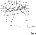
- Fig. 1 shows a horizontal section through a revolving door 14 with already known monitoring devices 10 for monitoring the movement area 12 of the revolving door 14 for obstacles, the detection areas 26 of the distance sensors of the respective monitoring devices 10 being shown as a projection 28 onto the floor.
- the problem that arises from the use of conventional monitoring devices 10 becomes clear.
- the monitoring device 10 attached to the opposite hinge side 24 detects a section of the door frame 16 shortly before reaching the closed end position, which is interpreted by the monitoring device 10 as an obstacle located in the movement area 12 .
- the monitoring device 10 can cause the leaf 20 of the revolving door 14 to stop moving, so that the leaf 20 of the revolving door 14 cannot reach its closed end position and the revolving door 14 remains open.
- an object located in the vicinity of the open end position of the revolving door 14 can result in the revolving door 14 not being able to be opened completely.
- the invention provides for a virtual wall 30 to be provided for each of the end positions of the revolving door 14, which for the sake of simplicity is shown in FIG 2 to 4 is only shown for the open end position of the revolving door 14. It goes without saying that in a comparable way also one Virtual wall for the closed end position of the revolving door 14 can be provided.
- a specific distance value to the virtual wall is predefined for each of the distance sensors and for the respective door opening angle ⁇ , ie a predefined distance value is specified for each distance sensor and for each door opening angle ⁇ with respect to the virtual wall.
- the predetermined distance to the virtual wall 30 for a distance sensor closer to the axis of rotation A of the revolving door 14 is smaller than for a distance sensor more distant to the axis of rotation A of the revolving door 14, as is shown in FIG Fig. 4 can be seen particularly clearly.
- the predetermined distance value for the hinge-side monitoring device 10 becomes smaller as the door 20 of the revolving door 14 moves in the direction of the open end position of the revolving door 14 with increasing door opening angle ⁇ until the distance value specified for each distance sensor for the wing 20 of the revolving door 14 which is in the open end position is at least approximately zero.
- the specified distance value for the hinge-side monitoring device 10 becomes smaller when the wing 20 of the revolving door 14 moves in the direction of the closed end position of the revolving door 14 with decreasing door opening angle ⁇ until the distance value specified for each distance sensor is then at least approximately zero in the closed end position.
- the distance is measured by means of optical distance sensors, it also being conceivable that at least one distance sensor acoustically detects the distance.
- the distance detected by a respective distance sensor at a respective door opening angle is then compared with the distance value specified at this door opening angle by means of the evaluation device.
- the evaluation device takes into account at least one of the following parameters: the maximum door opening angle ⁇ max , the angle of inclination ⁇ of the detection area 26 of the respective one Distance sensors, a distance b 1 of the respective distance sensor to a vertical edge of the revolving door 14 oriented at least parallel to the axis of rotation A and facing the axis of rotation A and / or the width b of the wing 20 of the revolving door 14.
- At least one of the parameters listed above can be found in FIG Sensor device of the monitoring device 10 may be stored.
- the sensor device is designed to independently measure the inclination angle ⁇ and / or the door opening angle ⁇ , for example by means of a potentiometer, a gyroscope or an acceleration sensor.
- the evaluation device 10 determines, when comparing the distance measured at a respective door opening angle ⁇ with the specified distance value, that the measured distance is less than the specified distance value, the evaluation device 10 interprets this event as an obstacle located in the movement area 12.
- the signal generating device is caused to generate a signal.
- This signal can be, for example, an acoustic warning tone or an optical signal.
- the signal preferably causes braking, in particular stopping the movement of the wing 20 of the revolving door 14, so that a collision of the wing 20 of the revolving door 14 with the obstacle is avoided.
Landscapes
- Physics & Mathematics (AREA)
- Life Sciences & Earth Sciences (AREA)
- General Life Sciences & Earth Sciences (AREA)
- General Physics & Mathematics (AREA)
- Geophysics (AREA)
- Engineering & Computer Science (AREA)
- Acoustics & Sound (AREA)
- Environmental & Geological Engineering (AREA)
- Geology (AREA)
- Remote Sensing (AREA)
- Civil Engineering (AREA)
- Structural Engineering (AREA)
- Power-Operated Mechanisms For Wings (AREA)
Abstract
Description
- Die vorliegende Erfindung betrifft eine Überwachungseinrichtung zur Überwachung des Bewegungsbereichs einer Drehtür beim Öffnen und/oder Schließen auf Hindernisse mit einer mit dem Flügel der Drehtür mitbewegenden Sensoreinrichtung mit mindestens einem Abstandssensor und einer Auswerteeinrichtung zur Auswertung des von dem Abstandssensor gemessenen Abstands bei verschiedenen Türöffnungswinkeln.
- Eine derartige Überwachungseinrichtung ist grundsätzlich bekannt und wird bei einer an einem Türrahmen mittels eines Türbandes drehbar gelagerten Drehtür dazu verwendet, ein sich gegebenenfalls im Bewegungsbereich der Drehtür befindliches Hindernis bzw. Objekt, wie zum Beispiel eine Person, zu erkennen. Hierfür ist üblicherweise auf der Bandseite des Flügels der Drehtür eine erste Sensoreinrichtung vorgesehen, welche den Bewegungsbereich in Richtung der Offenstellung der Drehtür überwacht, wohingegen auf der Bandgegenseite eine zweite Sensoreinrichtung den Bewegungsbereich in Richtung der Geschlossenstellung der Drehtür erfasst.
- Die Erkennung des Objekts erfolgt beispielweise dadurch, dass die Auswerteeinrichtung der Überwachungseinrichtung eine Abweichung des bei einem bestimmten Türöffnungswinkel gemessenen Abstands von einem jeweiligen vorgegeben, hindernisfreien, Abstandswert ermittelt. Bei Detektion eines Objekts im Bewegungsbereich der Drehtür, d.h. bei Abweichung des bei einem bestimmten Türöffnungswinkel gemessenen Abstands von einem jeweiligen vorgegebenen Abstandswert kann ein Signal einer Signalerzeugungseinrichtung der Sensoreinrichtung dazu dienen, eine Bewegung der Drehtür zu stoppen, so dass das Objekt und/oder die Tür keinen Schaden nehmen.
- Damit die Drehtür rechtzeitig vor einer Kollision mit dem Hindernis gestoppt werden kann, wird ein in Bewegungsrichtung der Drehtür vorgelagerter Bereich von der Sensoreinrichtung erfasst. Hierbei besteht jedoch die Möglichkeit, dass der Türrahmen bei einer Schließbewegung der Drehtür in den vorgelagerten Erfassungsbereich hineinragt und als Hindernis wahrgenommen wird. Infolgedessen wird die Bewegung der Drehtür gestoppt, so dass die Drehtür nicht vollständig geschlossen werden kann. Ebenso ist es möglich, dass sich die Drehtür nicht vollständig öffnen lässt, wenn ein ständiges (Wand) oder temporäres Hindernis, wie zum Beispiel eine bewegliche Trennwand, sich im Bereich der vollständigen Offenstellung der Drehtür befindet und somit als Hindernis erkannt wird.
- Um diesen Nachteilen zu begegnen, sehen bisherige Lösungsvorschläge unter anderem vor, dass Randbereiche des Flügels der Drehtür von der Sensoreinheit grundsätzlich nicht erfasst werden. Ferner kann vorgesehen sein, dass die Auswerteeinrichtung der Sensoreinheit Signale ignoriert, welche im Bereich der Endstellungen der Drehtür von den jeweiligen Abstandssensoren erzeugt werden. Damit die Auswerteeinrichtung die in den Bereichen der Endstellungen erzeugten Signale von den dazwischen erzeugten Signalen differenzieren kann, ist es erforderlich, dass die Endstellungen von der Auswerteeinrichtung erfasst werden. Hierfür wird ein aufwendiger Initialisierungsvorgang benötigt, bei welchem eine vollständige Bewegung des Flügels der Drehtür zwischen den beiden Endstellungen der Drehtür vollführt wird. Ein derartiger Initialisierungsvorgang kann überdies jedes Mal dann nötig sein, wenn zum Beispiel die Trennwand umgestellt wird. Hinzu kommt, dass der Initialisierungsvorgang fehlerbehaftet sein kann, da gegebenenfalls nicht sämtliche stationären Einrichtungen im Bereich der Endstellung korrekt erfasst worden sind, beispielsweise bei einer transparenten Wand aus Glas oder wenn sich ein Heizkörper oder ein Regal vor der Wand befindet.
- Bei den eben geschilderten Lösungsvorschlägen lässt sich daher ein ausreichender Kollisionsschutz nicht oder nur in aufwendiger Weise erreichen.
- Es ist daher eine Aufgabe der Erfindung, die Überwachung des Bewegungsbereichs einer Drehtür beim Öffnen und/oder Schließen auf Hindernisse zu verbessern. Insbesondere ist es eine Aufgabe der Erfindung, eine Überwachungseinrichtung zu schaffen, welche eine vollständigere Absicherung des Bewegungsbereichs der Drehtür ermöglicht, aber keinen Initialisierungsvorgang benötigt.
- Die Aufgabe wird mit einer Überwachungseinrichtung mit den Merkmalen des Anspruchs 1, einer Drehtür nach Anspruch 13 und einem Verfahren gemäß Anspruch 15 gelöst.
- Die erfindungsgemäße Überwachungseinrichtung zur Überwachung des Bewegungsbereichs einer Drehtür beim Öffnen und/oder Schließen auf Hindernisse umfasst eine mit dem Flügel der Drehtür mitbewegende Sensoreinrichtung mit mindestens einem Abstandssensor und einer Auswerteeinrichtung zur Auswertung des von dem Abstandssensor gemessenen Abstands bei verschiedenen Türöffnungswinkeln und eine Signalerzeugungseinrichtung zur Erzeugung eines Signals bei Abweichung des bei einem bestimmten Türöffnungswinkel gemessenen Abstands von einem jeweiligen vorgegeben Abstandswert, wobei der für einen jeweiligen Türöffnungswinkel vorgegebene Abstandswert eines jeweiligen Abstandssensors in Bezug auf eine virtuelle Wand festgelegt ist, die für eine Endstellung der Drehtür definiert ist.
- Der Erfindung liegt der allgemeine Gedanke zugrunde, den Bewegungsbereich einer Drehtür mittels einer Überwachungseinrichtung noch besser auf Hindernisse zu überwachen, indem mit Hilfe einer eine Endstellung einer Drehtür definierenden virtuellen Wand ein für einen jeweiligen Türöffnungswinkel vorgegebener Abstandswert zu einem Abstandssensor einer Sensoreinrichtung der Überwachungseinrichtung referenziert wird, wobei der vorgegebene Abstandswert dazu dient, mit einem von dem Abstandssensor bei einem bestimmten Türöffnungswinkel gemessenen Abstand mittels einer Auswerteeinrichtung der Sensoreinrichtung verglichen zu werden, und wobei ferner eine Signalerzeugungseinrichtung ein Signal erzeugt, wenn der gemessene Abstand von dem vorgegebenen Abstandswert bei einem bestimmten Türöffnungswinkel abweicht. Die virtuelle Wand ist dabei keine physisch greifbare Wand, bewirkt jedoch ebenso wie eine reale Wand, dass eine Bewegung des Flügels der Drehtür vor der Wand stoppt.
- Da die Endstellung der Drehtür die Position der virtuellen Wand definiert, ergibt sich der Vorteil, dass ein Initialisierungsvorgang entbehrlich ist, welcher zur Bestimmung des tatsächlichen Erfassungsbereichs des Sensors dient.
- Indem nur die virtuelle Wand eine Referenzfläche für die Überwachungseinrichtung darstellt, besteht ein weiterer Vorteil der Erfindung darin, dass ein sich in Bewegungsrichtung gesehen hinter der virtuellen Wand befindliches Objekt, beispielsweise der Rahmen einer Drehtür, kein Stoppen der Bewegung der Drehtür bewirkt, auch wenn das Objekt vom Abstandssensor der Überwachungseinrichtung erfasst wird. Somit lässt sich ein vollständiges Öffnen bzw. Schließen der Drehtür erreichen. Gleichzeitig werden sämtliche Objekte, welche sich zwischen der virtuellen Wand und der Drehtür befinden, als Hindernis erkannt.
- Vorteilhafte Ausbildungen der Erfindung sind den Unteransprüchen, der Beschreibung und den Zeichnungen zu entnehmen.
- Insbesondere bei automatischen Drehtüren, welche mittels einer motorischen Antriebseinheit bewegt werden, kann das von der Signalerzeugungseinrichtung erzeugte Signal nicht nur dazu dienen, die Bewegung der Drehtür zu stoppen, sondern überdies die Bewegung zu reversieren, wodurch sich die Drehtür in entgegengesetzter Richtung von dem Objekt wegbewegt.
- Damit ein Hindernis in Bewegungsrichtung der Drehtür rechtzeitig erkannt werden kann, ist es vorteilhaft, wenn ein Erfassungsbereich des Abstandssensors bezüglich des Flügels der Drehtür unter einem Neigungswinkel geneigt ist. Aufgrund dessen Neigung ist der Erfassungsbereich des Abstandssensors stets vorgelagert, wodurch die Überwachungseinrichtung ein Hindernis erkennt, bevor der Flügel der Drehtür mit diesem kollidiert.
- Die Genauigkeit der Überwachungseinrichtung lässt sich erhöhen, indem die Auswertung des von dem Abstandssensor gemessenen Abstands mittels der Auswerteeinrichtung in Abhängigkeit von mindestens einem der folgenden Parameter erfolgt:
- dem maximalen Türöffnungswinkel der Drehtür,
- dem Neigungswinkel des Erfassungsbereichs des Abstandssensors,
- einer Position des Abstandssensors an dem Flügel der Drehtür, insbesondere einem Abstand des Abstandssensors zu einer bezüglich der Drehachse der Drehtür zumindest annähernd parallel ausgerichteten Hochkante des Flügels der Drehtür, und/oder
- der Breite des Flügels der Drehtür.
- Diese Parameter können beispielsweise bereits in der Überwachungseinrichtung abgespeichert sein. Es ist aber auch möglich, dass die Überwachungseinrichtung dazu ausgebildet ist, zumindest den Neigungswinkel und/oder den Türöffnungswinkel eigenständig zu messen. Hierfür kann bzw. können ein Potentiometer und/oder ein Beschleunigungssensor und/oder ein Gyroskop vorgesehen sein.
- Der Kollisionsschutz ist besonders effizient, wenn die Signalerzeugungseinrichtung bei Unterschreitung des bei einem bestimmten Türöffnungswinkel gemessenen Abstands von dem jeweiligen vorgegeben Abstandswert ein Signal erzeugt.
- Handelt es sich bei dem Hindernis bzw. Objekt um eine Person, so kann diese vor einer bevorstehenden Kollision mit der Drehtür gewarnt werden, indem das von der Signalerzeugungseinrichtung erzeugte Signal ein optisches Signal und/oder ein akustisches Signal ist. Für das optische Signal kann eine Lichtquelle vorgesehen sein, welche beispielsweise gut erkennbar an der Drehtür angebracht ist. Ebenso kann für das akustische Signal ein Lautsprecher vorgesehen sein, welcher einen Signalton bei einer bevorstehenden Kollision mit der Drehtür abgibt. Zusätzlich oder alternativ kann das von der Signalerzeugungseinrichtung erzeugte Signal auch das Stoppen der Drehflügeltür bewirken, wodurch eine Kollision verhindert oder zumindest abgemildert werden kann.
- Vorteilhafterweise sind zwei Endstellungen vorgesehen, welche jeweils durch eine virtuelle Wand definiert sind und zwischen welchen der Flügel der Drehtür bewegbar ist. Dabei können ein maximaler Türöffnungswinkel eine Offenendstellung und ein minimaler Türöffnungswinkel, insbesondere ein Türöffnungswinkel von zumindest annähernd 0°, eine Geschlossenendstellung der Drehtür definieren.
- Bevorzugt wird der vorgegebene Abstandswert bei einer Bewegung des Flügels der Drehtür in Richtung der Offenendstellung der Drehtür mit zunehmendem Türöffnungswinkel kleiner. Dahingegen wird der vorgegebene Abstandswert bei einer Bewegung des Flügels in Richtung der Geschlossenendstellung der Drehtür mit abnehmendem Türöffnungswinkel kleiner. Hat der Flügel der Drehtür dann eine der Endstellungen erreicht, so ist der vorgegebene Abstand in Richtung dieser Endstellung zumindest annähernd null. Es versteht sich, dass der vorgegebene Abstand in Richtung der jeweils anderen Endstellung dann einen maximalen Wert erreicht.
- Um eine möglichst lückenlose Überwachung des Bewegungsbereichs der Drehtür zu erreichen, können mehrere Abstandssensoren vorgesehen sein, wobei die Erfassungsbereiche mindestens zweier, insbesondere benachbarter, Abstandssensoren zumindest teilweise überlappen. Die Sensoren bilden dann einen vorhangartigen Erfassungsbereich.
- Gemäß einem Aspekt der Erfindung ist für einen gegebenen Türöffnungswinkel der vorgegebene Abstand für einen zur Drehachse der Drehtür näheren Abstandssensor kleiner ist als für einen zur Drehachse der Drehtür entfernteren Abstandssensor.
- Zur berührungslosen Erfassung des Bewegungsbereichs der Drehtür kann mindestens ein Abstandssensor ein optischer Abstandssensor sein. Dabei sind verschiedene Arten der Erfassung des Bewegungsbereichs der Drehtür denkbar. So kann ein optischer Abstandssensor den Bewegungsbereich mittels mindestens eines Aktiv-Infrarot Strahls (AIR) abtasten. Der Aktiv-Infrarot Strahl wird dabei an einer Oberfläche reflektiert, wobei ein Hindernis anhand der Intensitätsänderung des reflektierten Aktiv-Infrarot Strahls erkannt werden kann. Auch lässt sich ein Abstand zu dem Boden innerhalb des Bewegungsbereichs der Drehtür bzw. zu einem Hindernis trigonometrisch bestimmen, wobei der optische Abstandssensor eine Sendeeinheit sowie eine zu der Sendeeinheit beabstandete Empfangseinheit umfasst. Ferner lässt sich der Abstand anhand der Laufzeit eines Lichtpulses, d.h. nach dem sogenannten Time-of-Flight-Prinzip messen (TOF-Sensoren). Es versteht sich, dass zusätzlich oder alternativ auch akustische Abstandssensoren verwendet werden können, welche einen Abstand in analoger Weise zu den vorstehend beschriebenen optischen Abstandssensoren erfassen.
- Nachfolgend wird die Erfindung rein beispielhaft anhand einer möglichen Ausführungsform unter Bezugnahme auf die beigefügten Zeichnungen beschrieben. Es zeigen:
- Fig. 1
- einen Horizontalschnitt einer Drehtür mit einer bekannten Überwachungseinrichtung zur Überwachung des Bewegungsbereichs der Drehtür auf Hindernisse;
- Fig. 2
- eine Drehtür mit erfindungsgemäßer Überwachungseinrichtung in einer Geschlossenstellung;
- Fig. 3
- die Drehtür von
Fig. 2 in einer ersten Öffnungsstellung; und - Fig. 4
- die Drehtür von
Fig. 2 in einer vorangeschrittenen zweiten Öffnungsstellung. - Die Figuren zeigen jeweils eine Überwachungseinrichtung 10 zur Überwachung des Bewegungsbereichs 12 einer Drehtür 14 beim Öffnen und/oder Schließen auf Hindernisse. Die Drehtür 14 umfasst einen an einem Türrahmen 16 um eine Drehachse A mittels eines Türbandes 18 drehbeweglich gelagerten Flügel 20, welcher zwischen zwei Endstellungen bewegbar ist. Dabei definieren ein minimaler Türöffnungswinkel αmin von zumindest annähernd 0° eine Geschlossenendstellung und ein maximaler Türöffnungswinkel αmax eine Offenendstellung des Flügels 20.
- Auf gegenüberliegenden Seiten des Flügels 20 ist jeweils eine Überwachungseinrichtung 10 angebracht. Konkret ist jeweils eine Überwachungseinrichtung 10 auf der Bandseite 22 des Flügels 20 als auch auf der Bandgegenseite 24 des Flügels 20 angebracht, wobei in den
Fig. 2 bis 4 lediglich die auf der Bandseite 22 angebrachte Überwachungseinrichtung 10 dargestellt ist. Die bandseitige Überwachungseinrichtung 10 dient zur Überwachung des Bewegungsbereichs 12 in Richtung der Offenendstellung des Flügels 20, wohingegen die bandgegenseitige Überwachungseinrichtung 10 verwendet wird, um den Bewegungsbereich 12 in Richtung der Geschlossenendstellung des Flügels 20 zu überwachen. - Jede der Überwachungseinrichtungen 10 umfasst eine sich mit dem Flügel 20 der Drehtür 14 mitbewegende Sensoreinrichtung, welche in den Figuren nicht genauer dargestellt ist. Die Sensoreinrichtung umfasst wiederum mindestens einen Abstandssensor und eine Auswerteeinrichtung zur Auswertung des von dem Abstandssensor gemessenen Abstands bei verschiedenen Türwinkeln. Konkret umfasst die Sensoreinrichtung mehrere Abstandssensoren, deren Erfassungsbereiche sich derart teilweise überlappen, dass sie zusammen einen vorhangartigen Erfassungsbereich 26 bilden. Wie besonders anhand der
Fig. 2 bis 4 zu erkennen ist, ist der vorhangartige Erfassungsbereich 26 der Abstandssensoren gegenüber dem Flügel 20 der Drehtür 14 unter einem Neigungswinkel β geneigt. - Ferner umfasst jede der Überwachungseinrichtungen 10 eine in den Figuren ebenfalls nicht genauer dargestellte Signalerzeugungseinrichtung, welche dazu dient, ein Signal zu erzeugen, wenn ein von einem Abstandssensor bei einem bestimmten Türöffnungswinkel α des Flügels 20 gemessener Abstand von einem vorgegebenen Abstand abweicht.
-
Fig. 1 zeigt einen Horizontalschnitt durch eine Drehtür 14 mit bereits bekannten Überwachungseinrichtungen 10 zur Überwachung des Bewegungsbereichs 12 der Drehtür 14 auf Hindernisse, wobei die Erfassungsbereiche 26 der Abstandssensoren der jeweiligen Überwachungseinrichtungen 10 als Projektion 28 auf den Boden dargestellt sind. - Anhand von
Fig. 1 wird die Problematik deutlich, welche sich durch die Verwendung von konventionellen Überwachungseinrichtungen 10 ergibt. Bei einer Bewegung des Flügels 20 der Drehtür 14 in Richtung der Geschlossenendstellung der Drehtür 14 erfasst die an der Bandgegenseite 24 angebrachte Überwachungseinrichtung 10 kurz vor Erreichen der Geschlossenendstellung einen Abschnitt des Türrahmens 16, was von der Überwachungseinrichtung 10 als ein im Bewegungsbereich 12 befindliches Hindernis interpretiert wird. Um eine Kollision mit diesem vermeintlichen Hindernis zu vermeiden, kann die Überwachungseinrichtung 10 einen Bewegungsstopp des Flügels 20 der Drehtür 14 veranlassen, so dass der Flügel 20 der Drehtür 14 nicht in dessen Geschlossenendstellung gelangen kann und die Drehtür 14 bleibt offen. In vergleichbarer Weise kann ein sich in der Nähe der Offenendstellung der Drehtür 14 befindliches Objekt dazu führen, dass sich die Drehtür 14 nicht vollständig öffnen lässt. - Um dieser Problematik zu begegnen ist erfindungsgemäß vorgesehen, für jede der Endstellungen der Drehtür 14 jeweils eine virtuelle Wand 30 vorzusehen, welche der Einfachheit halber in
Fig. 2 bis 4 lediglich für die Offenendstellung der Drehtür 14 dargestellt ist. Es versteht sich, dass in vergleichbarer Weise auch eine virtuelle Wand für die Geschlossenendstellung der Drehtür 14 vorgesehen sein kann. - Für jeden der Abstandssensoren sowie für jeweilige Türöffnungswinkel α ist ein bestimmter Abstandswert zu der virtuellen Wand vorgegeben, d.h. für jeden Abstandssensor und für jeweilige Türöffnungswinkel α ist in Bezug auf die virtuelle Wand ein vorgegebener Abstandswert festgelegt. Dabei ist für einen gegebenen Türöffnungswinkel α der vorgegebene Abstand zur virtuellen Wand 30 für einen zur Drehachse A der Drehtür 14 näheren Abstandssensor kleiner als für einen zur Drehachse A der Drehtür 14 entfernteren Abstandssensor, wie anhand von
Fig. 4 besonders deutlich zu erkennen ist. Überdies wird der vorgegebene Abstandswert für die bandseitige Überwachungseinrichtung 10 bei einer Bewegung des Flügels 20 der Drehtür 14 in Richtung der Offenendstellung der Drehtür 14 mit zunehmenden Türöffnungswinkel α kleiner, bis der für jeden Abstandssensor vorgegebene Abstandswert bei dem in der Offenendstellung befindliche Flügel 20 der Drehtür 14 zumindest annähernd null ist. Dahingegen wird der vorgegebene Abstandswert für die bandgegenseitige Überwachungseinrichtung 10 bei einer Bewegung des Flügels 20 der Drehtür 14 in Richtung der Geschlossenendstellung der Drehtür 14 mit abnehmenden Türöffnungswinkel α kleiner, bis der für jeden Abstandssensor vorgegebene Abstandswert dann in der Geschlossenendstellung zumindest annähernd null ist. - In dem in
Fig. 2 bis 4 dargestellten Ausführungsbeispiel wird der Abstand mittels optischer Abstandssensoren gemessen, wobei es auch denkbar ist, dass mindestens ein Abstandssensor den Abstand akustisch erfasst. Der von einem jeweiligen Abstandssensor bei einem jeweiligen Türöffnungswinkel erfasste Abstand wird anschließend mit dem bei diesem Türöffnungswinkel vorgegebenen Abstandswert mittels der Auswerteeinrichtung verglichen. Dabei berücksichtigt die Auswerteeinrichtung mindestens einen der folgenden Parameter: den maximalen Türöffnungswinkel αmax, den Neigungswinkel β des Erfassungsbereichs 26 der jeweiligen Abstandssensoren, einen Abstand b1 des jeweiligen Abstandssensors zu einer bezüglich der Drehachse A zumindest parallel ausgerichteten und der Drehachse A zugewandten Hochkante der Drehtür 14 und/oder die Breite b des Flügels 20 der Drehtür 14. Dabei kann mindestens einer der vorstehend aufgeführten Parameter in der Sensoreinrichtung der Überwachungseinrichtung 10 gespeichert sein. Es ist aber auch denkbar, dass die Sensoreinrichtung dazu ausgebildet ist, den Neigungswinkel β und/oder den Türöffnungswinkel α eigenständig zu messen, beispielsweise mittels eines Potentiometers, eines Gyroskops oder eines Beschleunigungssensors. - Stellt die Auswerteeinrichtung beim Vergleich des bei einem jeweiligen Türöffnungswinkel α gemessenen Abstands mit dem vorgegebenen Abstandswert fest, dass der gemessene Abstand den vorgegebenen Abstandswert unterschreitet, so interpretiert die Auswerteeinrichtung 10 dieses Ereignis als ein im Bewegungsbereich 12 befindliches Hindernis. Infolgedessen wird die Signalerzeugungseinrichtung dazu veranlasst, ein Signal zu erzeugen. Dieses Signal kann beispielsweise ein akustischer Warnton oder ein optisches Signal sein. Bevorzugt veranlasst das Signal das Abbremsen insbesondere das Stoppen der Bewegung des Flügels 20 der Drehtür 14, so dass eine Kollision des Flügels 20 der Drehtür 14 mit dem Hindernis vermieden wird.
-
- 10
- Überwachungseinrichtung
- 12
- Bewegungsbereich
- 14
- Drehtür
- 16
- Türrahmen
- 18
- Türband
- 20
- Flügel
- 22
- Bandseite
- 24
- Bandgegenseite
- 26
- Erfassungsbereich
- 28
- Projektion des Erfassungsbereichs
- 30
- virtuelle Wand
- A
- Drehachse
- α
- Türöffnungswinkel
- αmin
- minimaler Türöffnungswinkel
- αmax
- maximaler Türöffnungswinkel
- β
- Neigungswinkel
- b1
- Abstand
- b
- Breite des Flügels
Claims (16)
- Überwachungseinrichtung (10) zur Überwachung des Bewegungsbereichs (12) einer Drehtür (14) beim Öffnen und/oder Schließen auf Hindernisse mit einer mit dem Flügel (20) der Drehtür (14) mitbewegenden Sensoreinrichtung mit mindestens einem Abstandssensor und einer Auswerteeinrichtung zur Auswertung des von dem Abstandssensor gemessenen Abstands bei verschiedenen Türöffnungswinkeln (α) und einer Signalerzeugungseinrichtung zur Erzeugung eines Signals bei Abweichung des bei einem bestimmten Türöffnungswinkel (α) gemessenen Abstands von einem jeweiligen vorgegeben Abstandswert,
dadurch gekennzeichnet, dass
der für einen jeweiligen Türöffnungswinkel (α) vorgegebene Abstandswert eines jeweiligen Abstandssensors in Bezug auf eine virtuelle Wand (30) festgelegt ist, die für eine Endstellung der Drehtür (14) definiert ist. - Überwachungseinrichtung (10) nach Anspruch 1,
dadurch gekennzeichnet, dass
ein Erfassungsbereich (26) des Abstandssensors bezüglich des Flügels (20) der Drehtür (14) unter einem Neigungswinkel (β) geneigt ist. - Überwachungseinrichtung (10) nach Anspruch 1 oder 2,
dadurch gekennzeichnet, dass
die Auswertung des von dem Abstandssensor gemessenen Abstands mittels der Auswerteeinrichtung in Abhängigkeit von mindestens einem der folgenden Parameter erfolgt:- dem maximalen Türöffnungswinkel (αmax) der Drehtür (14),- dem Neigungswinkel (β) des Erfassungsbereichs (26) des Abstandssensors,- einer Position des Abstandssensors an dem Flügel (20) der Drehtür (14), insbesondere einem Abstand (b1) des Abstandssensors zu einer bezüglich der Drehachse (A) der Drehtür (14) zumindest annähernd parallel ausgerichteten Hochkante des Flügels (20) der Drehtür (14), und/oder- der Breite (b) des Flügels (20) der Drehtür (14). - Überwachungseinrichtung (10) nach Anspruch 3,
dadurch gekennzeichnet, dass
zumindest einer der Parameter in der Überwachungseinrichtung (10) gespeichert ist und/oder die Überwachungseinrichtung (10) dazu ausgebildet ist, zumindest den Neigungswinkel (β) und/oder den Türöffnungswinkel (α) eigenständig zu messen. - Überwachungseinrichtung (10) nach zumindest einem der vorstehenden Ansprüche,
dadurch gekennzeichnet, dass
die Signalerzeugungseinrichtung bei Unterschreitung des bei einem bestimmten Türöffnungswinkel (α) gemessenen Abstands von dem jeweiligen vorgegeben Abstandswert ein Signal erzeugt. - Überwachungseinrichtung (10) nach zumindest einem der vorstehenden Ansprüche,
dadurch gekennzeichnet, dass
das Signal ein akustisches und/oder optisches Signal ist und/oder ein Stoppen des Flügels (14) der Drehtür (20) bewirkt. - Überwachungseinrichtung (10) nach zumindest einem der vorstehenden Ansprüche,
dadurch gekennzeichnet, dass
zwei Endstellungen vorgesehen sind, zwischen welchen der Flügel (20) der Drehtür (14) bewegbar ist, wobei ein maximaler Türöffnungswinkel (αmax) eine Offenendstellung und ein minimaler Türöffnungswinkel (αmin), insbesondere ein Türöffnungswinkel (α) von zumindest annähernd 0°, eine Geschlossenendstellung der Drehtür (14) definieren. - Überwachungseinrichtung (10) nach Anspruch 7,
dadurch gekennzeichnet, dass
der vorgegebene Abstandswert in Richtung der Offenendstellung der Drehtür (14) mit zunehmendem Türöffnungswinkel (α) kleiner wird, und/oder der vorgegebene Abstandswert in Richtung der Geschlossenendstellung der Drehtür (14) mit abnehmendem Türöffnungswinkel (α) kleiner wird. - Überwachungseinrichtung (10) nach zumindest einem der vorstehenden Ansprüche,
dadurch gekennzeichnet, dass
der vorgegebene Abstand in einer Endstellung zumindest annähernd null ist. - Überwachungseinrichtung (10) nach zumindest einem der vorstehenden Ansprüche,
dadurch gekennzeichnet, dass
mehrere Abstandssensoren vorgesehen sind, wobei die Erfassungsbereiche (26) mindestens zweier, insbesondere benachbarter, Abstandssensoren zumindest teilweise überlappen. - Überwachungseinrichtung (10) nach Anspruch 10,
dadurch gekennzeichnet, dass
für einen gegebenen Türöffnungswinkel (α) der vorgegebene Abstand für einen zur Drehachse (A) der Drehtür (14) näheren Abstandssensor kleiner ist als für einen zur Drehachse (A) der Drehtür (14) entfernteren Abstandssensor. - Überwachungseinrichtung (10) nach zumindest einem der vorstehenden Ansprüche,
dadurch gekennzeichnet, dass
mindestens ein Abstandssensor ein optischer oder ein akustischer Abstandssensor ist. - Drehtür (14) mit einem an einem Türrahmen (16) um eine Drehachse (A) drehbeweglich gelagerten Flügel (20) und einer Überwachungseinrichtung (10) nach zumindest einem der vorstehenden Ansprüche.
- Drehtür (14) nach Anspruch 13,
gekennzeichnet durch
eine Einrichtung, welche ein Abbremsen einer Bewegung des Flügels (20) der Drehtür (14), insbesondere ein Stoppen des Flügels (20) der Drehtür (14), in Ansprechen auf das Signal der Signalerzeugungseinrichtung veranlasst. - Verfahren zur Überwachung des Bewegungsbereichs (12) einer Drehtür (14) beim Öffnen und/oder Schließen auf Hindernisse mittels einer Überwachungseinrichtung (10) nach zumindest einem der Ansprüche 1 bis 12, die folgenden Schritte umfassend:- Festlegen eines vorgegebenen Abstandwerts zwischen mindestens einem Abstandssensor einer sich mit einem Flügel (20) der Drehtür (14) mitbewegenden Sensoreinrichtung und einer eine Endstellung der Drehtür (14) definierenden virtuellen Wand (30) für verschiedene Türöffnungswinkel (α) der Drehtür (14);- Erfassen eines Abstands mittels des mindestens einen Abstandssensors;- Auswerten des von dem Abstandssensor bei verschiedenen Türöffnungswinkeln (α) gemessenen Abstands mittels einer Auswerteeinrichtung der Sensoreinrichtung;- Vergleichen des gemessenen Abstands mit dem vorgegebenen Abstandswert; und- Erzeugen eines Signals mittels einer Signalerzeugungseinrichtung bei Abweichung, insbesondere bei Unterschreitung, des gemessenen Abstands von dem jeweiligen vorgegebenen Abstandswert.
- Verfahren nach Anspruch 15, ferner den Schritt umfassend:- Abbremsen, insbesondere Stoppen, einer Bewegung des Flügels (20) der Drehtür (14) in Ansprechen des von der Signalerzeugungseinrichtung erzeugten Signals.
Applications Claiming Priority (1)
| Application Number | Priority Date | Filing Date | Title |
|---|---|---|---|
| DE102018209454.3A DE102018209454A1 (de) | 2018-06-13 | 2018-06-13 | Überwachungseinrichtung |
Publications (2)
| Publication Number | Publication Date |
|---|---|
| EP3581747A1 true EP3581747A1 (de) | 2019-12-18 |
| EP3581747B1 EP3581747B1 (de) | 2023-11-29 |
Family
ID=66793897
Family Applications (1)
| Application Number | Title | Priority Date | Filing Date |
|---|---|---|---|
| EP19179115.1A Active EP3581747B1 (de) | 2018-06-13 | 2019-06-07 | Überwachungseinrichtung |
Country Status (4)
| Country | Link |
|---|---|
| EP (1) | EP3581747B1 (de) |
| CN (1) | CN110596780A (de) |
| DE (1) | DE102018209454A1 (de) |
| FI (1) | FI3581747T3 (de) |
Cited By (1)
| Publication number | Priority date | Publication date | Assignee | Title |
|---|---|---|---|---|
| CN118597938A (zh) * | 2024-07-01 | 2024-09-06 | 日立楼宇技术(广州)有限公司 | 一种防夹检测方法、装置、电子设备和存储介质 |
Families Citing this family (4)
| Publication number | Priority date | Publication date | Assignee | Title |
|---|---|---|---|---|
| CN113267155A (zh) * | 2020-02-17 | 2021-08-17 | 青岛海尔电冰箱有限公司 | 冰箱及开门角度检测方法 |
| CN111577059B (zh) * | 2020-04-17 | 2021-09-28 | 佛山科学技术学院 | 基于数字陀螺仪的门开关检测系统 |
| CN113256946B (zh) * | 2021-06-21 | 2021-12-03 | 广州朗国电子科技股份有限公司 | 一种开门预警系统和方法 |
| DE102022207301A1 (de) * | 2022-07-18 | 2024-01-18 | Geze Gmbh | Türanordnung und Türschließer für eine solche Türanordnung |
Citations (4)
| Publication number | Priority date | Publication date | Assignee | Title |
|---|---|---|---|---|
| US4851746A (en) * | 1987-04-15 | 1989-07-25 | Republic Industries, Inc. | Sensing apparatus for automatic door |
| EP1619469A1 (de) * | 2004-07-22 | 2006-01-25 | Bea S.A. | Laser Abtast- und Detektionsvorrichtung zur Detektion um automatische Türen |
| DE102008044990A1 (de) * | 2008-08-29 | 2010-03-11 | Agtatec Ag | Verfahren und Vorrichtung zur Ansteuerung und/oder Überwachung eines motorisch angetriebenen Flügels während der Öffnungsphase |
| WO2019072344A1 (de) * | 2017-10-11 | 2019-04-18 | Pepperl+Fuchs Gmbh | Türsensoreinrichtung und verfahren zum betreiben einer türsensoreinrichtung |
Family Cites Families (4)
| Publication number | Priority date | Publication date | Assignee | Title |
|---|---|---|---|---|
| DE102007050334A1 (de) * | 2007-10-18 | 2009-04-23 | Efaflex Tor- Und Sicherheitssysteme Gmbh & Co. Kg | Verfahren und Einrichtung zur Steuerung eines vertikal oder horizontal bewegten Tores unter Absicherung der Torschließebene gegenüber Hindernissen |
| CN107143275A (zh) * | 2017-06-26 | 2017-09-08 | 晋江市西园万家红电机厂 | 一种卷帘门双向阻停系统及其方法 |
| CN107893589A (zh) * | 2017-11-07 | 2018-04-10 | 浙江科技学院 | 一种汽车门侧障碍开启阻尼系统及其控制方法 |
| CN108001461A (zh) * | 2017-12-12 | 2018-05-08 | 徐薇 | 地铁屏蔽门限界区智能防夹检测报警装置和方法 |
-
2018
- 2018-06-13 DE DE102018209454.3A patent/DE102018209454A1/de not_active Ceased
-
2019
- 2019-06-07 FI FIEP19179115.1T patent/FI3581747T3/fi active
- 2019-06-07 EP EP19179115.1A patent/EP3581747B1/de active Active
- 2019-06-13 CN CN201910510822.7A patent/CN110596780A/zh active Pending
Patent Citations (4)
| Publication number | Priority date | Publication date | Assignee | Title |
|---|---|---|---|---|
| US4851746A (en) * | 1987-04-15 | 1989-07-25 | Republic Industries, Inc. | Sensing apparatus for automatic door |
| EP1619469A1 (de) * | 2004-07-22 | 2006-01-25 | Bea S.A. | Laser Abtast- und Detektionsvorrichtung zur Detektion um automatische Türen |
| DE102008044990A1 (de) * | 2008-08-29 | 2010-03-11 | Agtatec Ag | Verfahren und Vorrichtung zur Ansteuerung und/oder Überwachung eines motorisch angetriebenen Flügels während der Öffnungsphase |
| WO2019072344A1 (de) * | 2017-10-11 | 2019-04-18 | Pepperl+Fuchs Gmbh | Türsensoreinrichtung und verfahren zum betreiben einer türsensoreinrichtung |
Cited By (1)
| Publication number | Priority date | Publication date | Assignee | Title |
|---|---|---|---|---|
| CN118597938A (zh) * | 2024-07-01 | 2024-09-06 | 日立楼宇技术(广州)有限公司 | 一种防夹检测方法、装置、电子设备和存储介质 |
Also Published As
| Publication number | Publication date |
|---|---|
| CN110596780A (zh) | 2019-12-20 |
| FI3581747T3 (fi) | 2024-02-14 |
| EP3581747B1 (de) | 2023-11-29 |
| DE102018209454A1 (de) | 2019-12-19 |
Similar Documents
| Publication | Publication Date | Title |
|---|---|---|
| EP3581747B1 (de) | Überwachungseinrichtung | |
| EP2506034B1 (de) | Sensorvorrichtung, Sicherheitsvorrichtung, Tor und Verfahren zur Kontrolle der Bewegung | |
| DE102004020426B4 (de) | Verfahren und Vorrichtung zur Kollisionsverhinderung einer Kraftfahrzeugtür | |
| EP2212498B1 (de) | Verfahren und einrichtung zur steuerung eines vertikal oder horizontal bewegten tores unter absicherung der torschliessebene gegenüber hindernissen | |
| EP3584400B1 (de) | Schutztür oder schutztor und verfahren zum betreiben einer schutztür oder eines schutztores | |
| DE102008044990B4 (de) | Verfahren und Vorrichtung zur Ansteuerung und/oder Überwachung eines motorisch angetriebenen Flügels während der Öffnungsphase | |
| DE69519066T2 (de) | Aufzugsvorrichtung zur Verhinderung des vorzeitigen Verschlusses von Schiebetüren | |
| EP1470314A1 (de) | EINRICHTUNG ZUR AUTOMATISCHEN BET TIGUNG EINES TORES, INSBESONDERE EINES HUBTORES | |
| EP1875030B1 (de) | Vorrichtung zur steuerung eines angetriebenen bewegungselements, zum beispiel einer tür | |
| EP3575534B1 (de) | Vorrichtung zur sensorischen absicherung der flügelbewegungen einer automatischen drehtür | |
| DE2432063C3 (de) | Einrichtung und Verfahren zur Türschließüberwachung in Nahverkehrsfahrzeugen | |
| EP2818620B1 (de) | Automatische Fenster- oder Türanlage | |
| DE102020119925A1 (de) | Automatische Drehflügeltür und Sensor | |
| DE19804632C2 (de) | Verfahren und Vorrichtung zur Ansteuerung und/oder Überwachung eines motorisch angetriebenen Flügels | |
| EP3695249B1 (de) | Türsensoreinrichtung und verfahren zum betreiben einer türsensoreinrichtung | |
| EP2276902B1 (de) | Verfahren und einrichtung zur steuerung eines vertikal oder horizontal bewegten tores unter absicherung der torschliessebene gegenüber hindernissen | |
| EP3639058A1 (de) | Laserscanner zur überwachung eines überwachungsbereichs | |
| EP3258297B1 (de) | Lichtgitteranordnung | |
| DE102006043615A1 (de) | Verfahren und Vorrichtung zum Erkennen eines Hindernisses in einem Öffnungsbereich einer verschließbaren Öffnung | |
| DE202013002006U1 (de) | Kontrolleinrichtung | |
| EP0676524B1 (de) | Schnellaufender Öffnungsabschluss | |
| EP1612363B1 (de) | Automatische Schiebetüranlage | |
| EP4265873B1 (de) | Verfahren zur steuerung einer türanlage | |
| DE102007025394A1 (de) | Sicherheitsvorrichtung und Verfahren zum Absichern einer Nebenschließkante einer automatischen Tür | |
| EP4571036B1 (de) | Sicherheitseinrichtung mit beschleunigungssensor für industrietore |
Legal Events
| Date | Code | Title | Description |
|---|---|---|---|
| PUAI | Public reference made under article 153(3) epc to a published international application that has entered the european phase |
Free format text: ORIGINAL CODE: 0009012 |
|
| STAA | Information on the status of an ep patent application or granted ep patent |
Free format text: STATUS: THE APPLICATION HAS BEEN PUBLISHED |
|
| AK | Designated contracting states |
Kind code of ref document: A1 Designated state(s): AL AT BE BG CH CY CZ DE DK EE ES FI FR GB GR HR HU IE IS IT LI LT LU LV MC MK MT NL NO PL PT RO RS SE SI SK SM TR |
|
| AX | Request for extension of the european patent |
Extension state: BA ME |
|
| STAA | Information on the status of an ep patent application or granted ep patent |
Free format text: STATUS: REQUEST FOR EXAMINATION WAS MADE |
|
| 17P | Request for examination filed |
Effective date: 20200615 |
|
| RBV | Designated contracting states (corrected) |
Designated state(s): AL AT BE BG CH CY CZ DE DK EE ES FI FR GB GR HR HU IE IS IT LI LT LU LV MC MK MT NL NO PL PT RO RS SE SI SK SM TR |
|
| RIN1 | Information on inventor provided before grant (corrected) |
Inventor name: HUCKER, MATTHIAS |
|
| STAA | Information on the status of an ep patent application or granted ep patent |
Free format text: STATUS: EXAMINATION IS IN PROGRESS |
|
| 17Q | First examination report despatched |
Effective date: 20220818 |
|
| P01 | Opt-out of the competence of the unified patent court (upc) registered |
Effective date: 20230510 |
|
| GRAP | Despatch of communication of intention to grant a patent |
Free format text: ORIGINAL CODE: EPIDOSNIGR1 |
|
| STAA | Information on the status of an ep patent application or granted ep patent |
Free format text: STATUS: GRANT OF PATENT IS INTENDED |
|
| INTG | Intention to grant announced |
Effective date: 20230810 |
|
| GRAS | Grant fee paid |
Free format text: ORIGINAL CODE: EPIDOSNIGR3 |
|
| GRAA | (expected) grant |
Free format text: ORIGINAL CODE: 0009210 |
|
| STAA | Information on the status of an ep patent application or granted ep patent |
Free format text: STATUS: THE PATENT HAS BEEN GRANTED |
|
| AK | Designated contracting states |
Kind code of ref document: B1 Designated state(s): AL AT BE BG CH CY CZ DE DK EE ES FI FR GB GR HR HU IE IS IT LI LT LU LV MC MK MT NL NO PL PT RO RS SE SI SK SM TR |
|
| REG | Reference to a national code |
Ref country code: GB Ref legal event code: FG4D Free format text: NOT ENGLISH |
|
| REG | Reference to a national code |
Ref country code: CH Ref legal event code: EP |
|
| REG | Reference to a national code |
Ref country code: DE Ref legal event code: R096 Ref document number: 502019010009 Country of ref document: DE |
|
| REG | Reference to a national code |
Ref country code: IE Ref legal event code: FG4D Free format text: LANGUAGE OF EP DOCUMENT: GERMAN |
|
| REG | Reference to a national code |
Ref country code: FI Ref legal event code: FGE |
|
| REG | Reference to a national code |
Ref country code: NO Ref legal event code: T2 Effective date: 20231129 |
|
| REG | Reference to a national code |
Ref country code: SE Ref legal event code: TRGR |
|
| REG | Reference to a national code |
Ref country code: LT Ref legal event code: MG9D |
|
| REG | Reference to a national code |
Ref country code: NL Ref legal event code: MP Effective date: 20231129 |
|
| PG25 | Lapsed in a contracting state [announced via postgrant information from national office to epo] |
Ref country code: GR Free format text: LAPSE BECAUSE OF FAILURE TO SUBMIT A TRANSLATION OF THE DESCRIPTION OR TO PAY THE FEE WITHIN THE PRESCRIBED TIME-LIMIT Effective date: 20240301 |
|
| PG25 | Lapsed in a contracting state [announced via postgrant information from national office to epo] |
Ref country code: IS Free format text: LAPSE BECAUSE OF FAILURE TO SUBMIT A TRANSLATION OF THE DESCRIPTION OR TO PAY THE FEE WITHIN THE PRESCRIBED TIME-LIMIT Effective date: 20240329 |
|
| PG25 | Lapsed in a contracting state [announced via postgrant information from national office to epo] |
Ref country code: LT Free format text: LAPSE BECAUSE OF FAILURE TO SUBMIT A TRANSLATION OF THE DESCRIPTION OR TO PAY THE FEE WITHIN THE PRESCRIBED TIME-LIMIT Effective date: 20231129 |
|
| PG25 | Lapsed in a contracting state [announced via postgrant information from national office to epo] |
Ref country code: ES Free format text: LAPSE BECAUSE OF FAILURE TO SUBMIT A TRANSLATION OF THE DESCRIPTION OR TO PAY THE FEE WITHIN THE PRESCRIBED TIME-LIMIT Effective date: 20231129 |
|
| PG25 | Lapsed in a contracting state [announced via postgrant information from national office to epo] |
Ref country code: LT Free format text: LAPSE BECAUSE OF FAILURE TO SUBMIT A TRANSLATION OF THE DESCRIPTION OR TO PAY THE FEE WITHIN THE PRESCRIBED TIME-LIMIT Effective date: 20231129 Ref country code: IS Free format text: LAPSE BECAUSE OF FAILURE TO SUBMIT A TRANSLATION OF THE DESCRIPTION OR TO PAY THE FEE WITHIN THE PRESCRIBED TIME-LIMIT Effective date: 20240329 Ref country code: GR Free format text: LAPSE BECAUSE OF FAILURE TO SUBMIT A TRANSLATION OF THE DESCRIPTION OR TO PAY THE FEE WITHIN THE PRESCRIBED TIME-LIMIT Effective date: 20240301 Ref country code: ES Free format text: LAPSE BECAUSE OF FAILURE TO SUBMIT A TRANSLATION OF THE DESCRIPTION OR TO PAY THE FEE WITHIN THE PRESCRIBED TIME-LIMIT Effective date: 20231129 Ref country code: BG Free format text: LAPSE BECAUSE OF FAILURE TO SUBMIT A TRANSLATION OF THE DESCRIPTION OR TO PAY THE FEE WITHIN THE PRESCRIBED TIME-LIMIT Effective date: 20240229 |
|
| PG25 | Lapsed in a contracting state [announced via postgrant information from national office to epo] |
Ref country code: NL Free format text: LAPSE BECAUSE OF FAILURE TO SUBMIT A TRANSLATION OF THE DESCRIPTION OR TO PAY THE FEE WITHIN THE PRESCRIBED TIME-LIMIT Effective date: 20231129 |
|
| PG25 | Lapsed in a contracting state [announced via postgrant information from national office to epo] |
Ref country code: RS Free format text: LAPSE BECAUSE OF FAILURE TO SUBMIT A TRANSLATION OF THE DESCRIPTION OR TO PAY THE FEE WITHIN THE PRESCRIBED TIME-LIMIT Effective date: 20231129 Ref country code: PL Free format text: LAPSE BECAUSE OF FAILURE TO SUBMIT A TRANSLATION OF THE DESCRIPTION OR TO PAY THE FEE WITHIN THE PRESCRIBED TIME-LIMIT Effective date: 20231129 Ref country code: NL Free format text: LAPSE BECAUSE OF FAILURE TO SUBMIT A TRANSLATION OF THE DESCRIPTION OR TO PAY THE FEE WITHIN THE PRESCRIBED TIME-LIMIT Effective date: 20231129 Ref country code: LV Free format text: LAPSE BECAUSE OF FAILURE TO SUBMIT A TRANSLATION OF THE DESCRIPTION OR TO PAY THE FEE WITHIN THE PRESCRIBED TIME-LIMIT Effective date: 20231129 Ref country code: HR Free format text: LAPSE BECAUSE OF FAILURE TO SUBMIT A TRANSLATION OF THE DESCRIPTION OR TO PAY THE FEE WITHIN THE PRESCRIBED TIME-LIMIT Effective date: 20231129 |
|
| PG25 | Lapsed in a contracting state [announced via postgrant information from national office to epo] |
Ref country code: DK Free format text: LAPSE BECAUSE OF FAILURE TO SUBMIT A TRANSLATION OF THE DESCRIPTION OR TO PAY THE FEE WITHIN THE PRESCRIBED TIME-LIMIT Effective date: 20231129 |
|
| PG25 | Lapsed in a contracting state [announced via postgrant information from national office to epo] |
Ref country code: CZ Free format text: LAPSE BECAUSE OF FAILURE TO SUBMIT A TRANSLATION OF THE DESCRIPTION OR TO PAY THE FEE WITHIN THE PRESCRIBED TIME-LIMIT Effective date: 20231129 |
|
| PG25 | Lapsed in a contracting state [announced via postgrant information from national office to epo] |
Ref country code: SK Free format text: LAPSE BECAUSE OF FAILURE TO SUBMIT A TRANSLATION OF THE DESCRIPTION OR TO PAY THE FEE WITHIN THE PRESCRIBED TIME-LIMIT Effective date: 20231129 |
|
| PG25 | Lapsed in a contracting state [announced via postgrant information from national office to epo] |
Ref country code: SM Free format text: LAPSE BECAUSE OF FAILURE TO SUBMIT A TRANSLATION OF THE DESCRIPTION OR TO PAY THE FEE WITHIN THE PRESCRIBED TIME-LIMIT Effective date: 20231129 Ref country code: SK Free format text: LAPSE BECAUSE OF FAILURE TO SUBMIT A TRANSLATION OF THE DESCRIPTION OR TO PAY THE FEE WITHIN THE PRESCRIBED TIME-LIMIT Effective date: 20231129 Ref country code: RO Free format text: LAPSE BECAUSE OF FAILURE TO SUBMIT A TRANSLATION OF THE DESCRIPTION OR TO PAY THE FEE WITHIN THE PRESCRIBED TIME-LIMIT Effective date: 20231129 Ref country code: IT Free format text: LAPSE BECAUSE OF FAILURE TO SUBMIT A TRANSLATION OF THE DESCRIPTION OR TO PAY THE FEE WITHIN THE PRESCRIBED TIME-LIMIT Effective date: 20231129 Ref country code: EE Free format text: LAPSE BECAUSE OF FAILURE TO SUBMIT A TRANSLATION OF THE DESCRIPTION OR TO PAY THE FEE WITHIN THE PRESCRIBED TIME-LIMIT Effective date: 20231129 Ref country code: DK Free format text: LAPSE BECAUSE OF FAILURE TO SUBMIT A TRANSLATION OF THE DESCRIPTION OR TO PAY THE FEE WITHIN THE PRESCRIBED TIME-LIMIT Effective date: 20231129 Ref country code: CZ Free format text: LAPSE BECAUSE OF FAILURE TO SUBMIT A TRANSLATION OF THE DESCRIPTION OR TO PAY THE FEE WITHIN THE PRESCRIBED TIME-LIMIT Effective date: 20231129 |
|
| PG25 | Lapsed in a contracting state [announced via postgrant information from national office to epo] |
Ref country code: PT Free format text: LAPSE BECAUSE OF FAILURE TO SUBMIT A TRANSLATION OF THE DESCRIPTION OR TO PAY THE FEE WITHIN THE PRESCRIBED TIME-LIMIT Effective date: 20240401 |
|
| PG25 | Lapsed in a contracting state [announced via postgrant information from national office to epo] |
Ref country code: PT Free format text: LAPSE BECAUSE OF FAILURE TO SUBMIT A TRANSLATION OF THE DESCRIPTION OR TO PAY THE FEE WITHIN THE PRESCRIBED TIME-LIMIT Effective date: 20240401 |
|
| REG | Reference to a national code |
Ref country code: DE Ref legal event code: R097 Ref document number: 502019010009 Country of ref document: DE |
|
| PLBE | No opposition filed within time limit |
Free format text: ORIGINAL CODE: 0009261 |
|
| STAA | Information on the status of an ep patent application or granted ep patent |
Free format text: STATUS: NO OPPOSITION FILED WITHIN TIME LIMIT |
|
| PG25 | Lapsed in a contracting state [announced via postgrant information from national office to epo] |
Ref country code: SI Free format text: LAPSE BECAUSE OF FAILURE TO SUBMIT A TRANSLATION OF THE DESCRIPTION OR TO PAY THE FEE WITHIN THE PRESCRIBED TIME-LIMIT Effective date: 20231129 |
|
| PG25 | Lapsed in a contracting state [announced via postgrant information from national office to epo] |
Ref country code: SI Free format text: LAPSE BECAUSE OF FAILURE TO SUBMIT A TRANSLATION OF THE DESCRIPTION OR TO PAY THE FEE WITHIN THE PRESCRIBED TIME-LIMIT Effective date: 20231129 |
|
| 26N | No opposition filed |
Effective date: 20240830 |
|
| PG25 | Lapsed in a contracting state [announced via postgrant information from national office to epo] |
Ref country code: MC Free format text: LAPSE BECAUSE OF FAILURE TO SUBMIT A TRANSLATION OF THE DESCRIPTION OR TO PAY THE FEE WITHIN THE PRESCRIBED TIME-LIMIT Effective date: 20231129 |
|
| REG | Reference to a national code |
Ref country code: CH Ref legal event code: PL |
|
| PG25 | Lapsed in a contracting state [announced via postgrant information from national office to epo] |
Ref country code: LU Free format text: LAPSE BECAUSE OF NON-PAYMENT OF DUE FEES Effective date: 20240607 |
|
| PG25 | Lapsed in a contracting state [announced via postgrant information from national office to epo] |
Ref country code: IE Free format text: LAPSE BECAUSE OF NON-PAYMENT OF DUE FEES Effective date: 20240607 |
|
| PG25 | Lapsed in a contracting state [announced via postgrant information from national office to epo] |
Ref country code: CH Free format text: LAPSE BECAUSE OF NON-PAYMENT OF DUE FEES Effective date: 20240630 Ref country code: BE Free format text: LAPSE BECAUSE OF NON-PAYMENT OF DUE FEES Effective date: 20240630 |
|
| PG25 | Lapsed in a contracting state [announced via postgrant information from national office to epo] |
Ref country code: FR Free format text: LAPSE BECAUSE OF NON-PAYMENT OF DUE FEES Effective date: 20240630 |
|
| REG | Reference to a national code |
Ref country code: BE Ref legal event code: MM Effective date: 20240630 |
|
| PGFP | Annual fee paid to national office [announced via postgrant information from national office to epo] |
Ref country code: SE Payment date: 20250618 Year of fee payment: 7 |
|
| REG | Reference to a national code |
Ref country code: AT Ref legal event code: MM01 Ref document number: 1636277 Country of ref document: AT Kind code of ref document: T Effective date: 20240607 |
|
| PG25 | Lapsed in a contracting state [announced via postgrant information from national office to epo] |
Ref country code: AT Free format text: LAPSE BECAUSE OF NON-PAYMENT OF DUE FEES Effective date: 20240607 |
|
| PG25 | Lapsed in a contracting state [announced via postgrant information from national office to epo] |
Ref country code: CY Free format text: LAPSE BECAUSE OF FAILURE TO SUBMIT A TRANSLATION OF THE DESCRIPTION OR TO PAY THE FEE WITHIN THE PRESCRIBED TIME-LIMIT; INVALID AB INITIO Effective date: 20190607 |
|
| PG25 | Lapsed in a contracting state [announced via postgrant information from national office to epo] |
Ref country code: HU Free format text: LAPSE BECAUSE OF FAILURE TO SUBMIT A TRANSLATION OF THE DESCRIPTION OR TO PAY THE FEE WITHIN THE PRESCRIBED TIME-LIMIT; INVALID AB INITIO Effective date: 20190607 |
|
| PG25 | Lapsed in a contracting state [announced via postgrant information from national office to epo] |
Ref country code: TR Free format text: LAPSE BECAUSE OF FAILURE TO SUBMIT A TRANSLATION OF THE DESCRIPTION OR TO PAY THE FEE WITHIN THE PRESCRIBED TIME-LIMIT Effective date: 20231129 |
|
| PGFP | Annual fee paid to national office [announced via postgrant information from national office to epo] |
Ref country code: GB Payment date: 20260626 Year of fee payment: 8 |
|
| PGFP | Annual fee paid to national office [announced via postgrant information from national office to epo] |
Ref country code: DE Payment date: 20260630 Year of fee payment: 8 |
|
| PGFP | Annual fee paid to national office [announced via postgrant information from national office to epo] |
Ref country code: NO Payment date: 20260622 Year of fee payment: 8 |
|
| PGFP | Annual fee paid to national office [announced via postgrant information from national office to epo] |
Ref country code: FI Payment date: 20260626 Year of fee payment: 8 |