EP3581472A1 - Lower vehicle-body structure and method of producing a lower vehicle-body structure - Google Patents
Lower vehicle-body structure and method of producing a lower vehicle-body structure Download PDFInfo
- Publication number
- EP3581472A1 EP3581472A1 EP19178995.7A EP19178995A EP3581472A1 EP 3581472 A1 EP3581472 A1 EP 3581472A1 EP 19178995 A EP19178995 A EP 19178995A EP 3581472 A1 EP3581472 A1 EP 3581472A1
- Authority
- EP
- European Patent Office
- Prior art keywords
- floor
- vehicle
- cross member
- floor cross
- bottom face
- Prior art date
- Legal status (The legal status is an assumption and is not a legal conclusion. Google has not performed a legal analysis and makes no representation as to the accuracy of the status listed.)
- Withdrawn
Links
- 230000003014 reinforcing effect Effects 0.000 claims description 24
- 125000006850 spacer group Chemical group 0.000 claims description 7
- 230000002787 reinforcement Effects 0.000 description 20
- 238000003466 welding Methods 0.000 description 16
- 230000005540 biological transmission Effects 0.000 description 13
- 229910000831 Steel Inorganic materials 0.000 description 7
- 239000010959 steel Substances 0.000 description 7
- 230000006835 compression Effects 0.000 description 3
- 238000007906 compression Methods 0.000 description 3
- 229910000838 Al alloy Inorganic materials 0.000 description 2
- 238000005266 casting Methods 0.000 description 1
- 230000001419 dependent effect Effects 0.000 description 1
- 238000003780 insertion Methods 0.000 description 1
- 230000037431 insertion Effects 0.000 description 1
- 238000012986 modification Methods 0.000 description 1
- 230000004048 modification Effects 0.000 description 1
- 230000035515 penetration Effects 0.000 description 1
- 239000000725 suspension Substances 0.000 description 1
Images








Classifications
-
- B—PERFORMING OPERATIONS; TRANSPORTING
- B62—LAND VEHICLES FOR TRAVELLING OTHERWISE THAN ON RAILS
- B62D—MOTOR VEHICLES; TRAILERS
- B62D25/00—Superstructure or monocoque structure sub-units; Parts or details thereof not otherwise provided for
- B62D25/20—Floors or bottom sub-units
- B62D25/2009—Floors or bottom sub-units in connection with other superstructure subunits
- B62D25/2036—Floors or bottom sub-units in connection with other superstructure subunits the subunits being side panels, sills or pillars
-
- B—PERFORMING OPERATIONS; TRANSPORTING
- B60—VEHICLES IN GENERAL
- B60N—SEATS SPECIALLY ADAPTED FOR VEHICLES; VEHICLE PASSENGER ACCOMMODATION NOT OTHERWISE PROVIDED FOR
- B60N2/00—Seats specially adapted for vehicles; Arrangement or mounting of seats in vehicles
- B60N2/005—Arrangement or mounting of seats in vehicles, e.g. dismountable auxiliary seats
- B60N2/015—Attaching seats directly to vehicle chassis
-
- B—PERFORMING OPERATIONS; TRANSPORTING
- B62—LAND VEHICLES FOR TRAVELLING OTHERWISE THAN ON RAILS
- B62D—MOTOR VEHICLES; TRAILERS
- B62D25/00—Superstructure or monocoque structure sub-units; Parts or details thereof not otherwise provided for
- B62D25/02—Side panels
- B62D25/025—Side sills thereof
-
- B—PERFORMING OPERATIONS; TRANSPORTING
- B62—LAND VEHICLES FOR TRAVELLING OTHERWISE THAN ON RAILS
- B62D—MOTOR VEHICLES; TRAILERS
- B62D25/00—Superstructure or monocoque structure sub-units; Parts or details thereof not otherwise provided for
- B62D25/20—Floors or bottom sub-units
-
- B—PERFORMING OPERATIONS; TRANSPORTING
- B62—LAND VEHICLES FOR TRAVELLING OTHERWISE THAN ON RAILS
- B62D—MOTOR VEHICLES; TRAILERS
- B62D27/00—Connections between superstructure or understructure sub-units
- B62D27/02—Connections between superstructure or understructure sub-units rigid
Definitions
- the present invention relates to a lower vehicle-body structure.
- a floor cross member extending in a vehicle with direction and a floor frame extending substantially in a vehicle longitudinal direction are provided on an upper face of a vehicle floor of an automotive vehicle for improving the vehicle-body rigidity or the like.
- a seat rail to guide a slide move of a seat is generally provided on the vehicle floor such that it extends substantially in the vehicle longitudinal direction.
- this seat rail is fixed to a vehicle body via brackets having the high rigidity. Thereby, the heavy seat can be stably supported.
- the seat rail is fixed so that the weight of the seat rail can be received by the floor cross member and the floor frame which are provided on the vehicle floor.
- an object of the present invention is to provide a lower vehicle-body structure which can properly improve the support rigidity of the vehicle floor for supporting the seat rail.
- An aspect relates to a lower vehicle-body structure which comprises a vehicle floor comprising a bottom face portion, a first floor cross member extending in a vehicle width direction and provided on the bottom face portion of the vehicle floor, the first floor cross member forming a closed cross section between the bottom face portion of the vehicle floor and the first floor cross member in a cross section perpendicular to the vehicle width direction, a second floor cross member extending in the vehicle width direction and provided on the bottom face portion of the vehicle floor, the second floor cross member forming a closed cross section between the bottom face portion of the vehicle floor and the second floor cross member in a cross section perpendicular to the vehicle width direction, the second floor cross member being spaced, substantially in a vehicle longitudinal direction, apart from the first floor cross member, a side sill extending substantially in the vehicle longitudinal direction and provided at an end portion, in the vehicle width direction, of the bottom face portion of the vehicle floor, the side sill forming a closed cross section between the bottom face portion of the vehicle floor and the side sill in a cross section perpen
- first floor cross member, the second floor cross member, the side sill, and/or the floor frame are arranged at respective positions such as to at least partially overlap each other substantially in the vehicle vertical direction and the attaching member is fixed to the side sill, the first floor cross member, and/or the second floor cross member.
- a frame structure is formed at the vehicle floor particularly by means of the side sill and the floor frame which respectively extend substantially in the vehicle longitudinal direction and having the closed cross section and the first floor cross member and the second floor cross member which respectively extend in the vehicle width direction and having the closed cross section.
- the members of this frame structure particularly are configured not to be offset substantially in the vehicle vertical direction. Accordingly, the support rigidity of the vehicle floor for attaching the seat can be properly improved, and also a sense of unity between the vehicle body and the seat can be improved by fixing the attaching member for attaching the seat to the frame structure.
- the side sill particularly includes a reinforcing plate which extends along a plane crossing the vehicle longitudinal direction inside the closed cross section of the side sill, and the reinforcing plate can be located at a position which at least partially overlaps at least one of the first floor cross member and the second floor cross member substantially in the vehicle longitudinal direction.
- the reinforcing plate particularly is arranged such as to at least partially overlap at least one of the first floor cross member and the second floor cross member substantially in the vehicle longitudinal direction.
- the reinforcing plate extending along the plane crossing the vehicle longitudinal direction particularly is provided at the side sill, the strength, in the vehicle vertical direction and in the vehicle width direction, of the side sill can be improved. Moreover, since the reinforcing plate particularly is located at the position at least partially overlapping at least one of the first floor cross member and the second floor cross member substantially in the vehicle longitudinal direction, the rigidity of the frame structure formed by means of the side sill, the floor frame, the first floor cross member, and/or the second floor cross member can be improved.
- the reinforcing plate particularly is located at a position which at least partially overlaps the first floor cross member substantially in the vehicle longitudinal direction, and the reinforcing plate particularly is located at a position which is offset, toward the second floor cross member, from a center, substantially in the vehicle longitudinal direction, of the first floor cross member.
- the reinforcing plate particularly is arranged such as to at least partially overlap the first floor cross member substantially in the vehicle longitudinal direction and the reinforcing plate particularly is arranged such as to be positioned offset, toward the second floor cross member, from a center, substantially in the vehicle longitudinal direction, of the first floor cross member.
- the reinforcing plate particularly is located at a position which at least partially overlaps the second floor cross member substantially in the vehicle longitudinal direction, and the reinforcing plate particularly is located at a position which is offset, toward the first floor cross member, from a center, substantially in the vehicle longitudinal direction, of the second floor cross member.
- the reinforcing plate particularly is arranged such as to at least partially overlap the second floor cross member substantially in the vehicle longitudinal direction and the reinforcing plate particularly is arranged such as to be positioned offset, toward the first floor cross member, from a center, substantially in the vehicle longitudinal direction, of the second floor cross member.
- the reinforcing plate particularly is formed as a gusset.
- the attaching member can be fixed to the side sill and any one of the first floor cross member and the second floor cross member.
- the attaching member can be fixed to the side sill and at least one of the first floor cross members and/or the second floor cross members.
- the attaching member can be fixed to a corner portion which particularly is formed by the side sill and any one of the first floor cross member and the second floor cross member, the support rigidity of the vehicle floor for attaching the seat can be properly improved.
- the vehicle floor particularly comprises a floor tunnel which is configured to protrude substantially upwardly from the bottom face portion and extend substantially in the vehicle longitudinal direction and an upper step portion which particularly is configured to rise substantially upwardly toward the floor tunnel from the bottom face portion in the vehicle width direction.
- the attaching member particularly is attached to the upper step portion and any one of the first floor cross member and the second floor cross member.
- the attaching member particularly is attached to the upper step portion and at least one of the first floor cross members and/or the second floor cross members.
- a substantially ladder-shaped structure particularly is formed at the vehicle floor by means of the side sill, the upper step portion, and/or the floor frame which respectively extend substantially in the vehicle longitudinal direction and the first floor cross member and/or the second floor cross member which respectively extend in the vehicle width direction. Since the attaching member can be fixed to a corner portion which particularly is formed by the upper step portion and any one of the first floor cross member and the second floor cross member, the support rigidity of the vehicle floor for attaching the seat can be properly improved.
- the upper step portion particularly configured to rise substantially upwardly can be provided between the vehicle floor and the floor tunnel, the rigidity of a boundary area between the vehicle floor and the floor tunnel can be improved. Since the attaching member particularly is fixed to the upper step portion, the support rigidity of the vehicle floor for attaching the seat can be properly improved.
- the lower vehicle-body structure particularly further comprises a spacer which can be interposed between the attaching member and the upper step portion and interconnects the attaching member and the upper step portion.
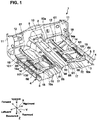
- FIG. 1 is a perspective view showing a lower vehicle-body structure according to the embodiment of the present invention.
- FIG. 2 is a plan view showing the lower vehicle-body structure.
- FIG. 3 is a bottom view showing the lower vehicle-body structure.
- a vehicle width direction, a vehicle longitudinal direction, and a vehicle vertical direction of an automotive vehicle 1 which is provided with the lower vehicle-body structure according to the present embodiment are respectively referred to as an X direction, a Y direction, and a Z direction.
- the automotive vehicle 1 provided with the lower vehicle-body structure comprises a vehicle floor 2 which constitutes a floor face of a space of a cabin, a pair of side sills 4 which extend substantially in the Y direction along both-side portions, in the X direction, of the vehicle floor 2, and a dash panel 10 which is provided in front of the vehicle floor 2.
- Each of the side sills 4 comprises a side sill inner 5 and a side sill outer (not illustrated).
- the side sill inner 5 is configured to have a hat-shaped cross section which is opened to an outward side in the X direction in a cross section perpendicular to the Y direction.
- the side sill outer is configured to have a hat-shaped cross section which is opened to an inward side in the X direction in the cross section perpendicular to the Y direction.
- the side sill inner 5 and the side sill outer are joined together such that a closed cross section which is continuous substantially in the Y direction is formed therebetween.
- the automotive vehicle 1 further comprises a pair of hinge pillars 11 which rise from respective front end portions of the right-and-left side sills 4 and extend substantially in the Z direction, and the dash panel 10 is provided between the pair of hinge pillars 11.
- a cabin space and an engine are partitioned from each other substantially in the Y direction by the dash panel 10.
- the vehicle floor 2 comprises a bottom face portion 3 and a floor tunnel 50 which is configured to protrude upwardly, substantially in the Z direction, from the bottom face portion 3 and extend substantially in the Y direction.
- the floor tunnel 50 is provided to extend substantially in the Y direction at a central portion, in the X direction, of the vehicle floor 2.
- a shape of a cross section of the floor tunnel 50, when viewed from the Y direction, is U-shaped which is opened to a downward side of the Z direction.
- a opening portion 50a for insertion of a shift lever (not illustrated) is formed at an upper face portion of the floor tunnel 50.
- a pair of reinforcing members 8 which are configured to extend substantially in the Y direction are joined to both-side portions, in the X direction, of the upper face portion of the floor tunnel 50 by welding, for example, whereby the rigidity of the floor tunnel 50 is increased.
- a pair of right-and-left floor frames 12 which extend substantially in the Y direction can be joined to the bottom face portion 3 of the vehicle floor 2.
- Each of the floor frames 12 particularly is provided between the floor tunnel 50 and the side sill 4 in the X direction.
- each of the floor frames 12 particularly is provided on an inward side, in the X direction, of the side sill 4.
- the floor frame 12 particularly is connected to a front end portion of the side sill 4 via a torque box 22 (shown in FIG. 3 ).
- the floor frame 12 particularly comprises an upper frame member 61 which can be joined to an upper face of the vehicle floor 2, for example by welding, and a lower frame member 62 which particularly is joined to a lower face of the vehicle floor 2, for example by welding.
- the upper frame member 61 and the lower frame member 62 are provided to face each other, interposing the vehicle floor 2 therebetween.
- the upper frame member 61 and the lower frame member 62 are provided to extend substantially in the Y direction, respectively.
- the lower frame member 62 and the bottom face portion 3 of the vehicle floor 2 jointly form a closed cross section which is continuous substantially in the Y direction. Referring to FIG.
- the upper frame member 61 of the present embodiment particularly is provided between a second floor cross member 16, which will be described later, and the dash panel 10 substantially in the Y direction.
- the upper frame member 61 particularly is not provided on a rearward side, substantially in the Y direction, of the second floor cross member 16.
- a pair of right-and-left first cross members 14 and a pair of right-and-left second floor cross members 16 particularly are joined to the upper face of the bottom face portion 3 of the vehicle floor 2 as floor cross members extending in the X direction, respectively.
- the second floor cross members 16 are provided to be spaced apart, rearwardly substantially in the Y direction, from the first floor cross members 14.
- An inside seat rail 99 and an outside seat rail 100 can be provided between the first floor cross member 14 and the second floor cross member 16.
- the first floor cross member 14 particularly is provided to extend between the floor tunnel 50 and the side sill 4.
- the right-and-left first floor cross members 14 particularly are provided on both sides, in the X direction, of the floor tunnel 50.
- These both cross members 14 can be arranged substantially at the same position substantially in the Y direction.
- the first floor cross member 14 can be a pressed part which is, for example, made of steel and can be configured to have a hat-shaped cross section which is opened downwardly in a cross section perpendicular to the X direction.
- the first floor cross member 14 and the vehicle floor 2 can jointly form a closed cross section which particularly is continuous in the X direction.
- the first floor cross member 14 particularly includes an upper face portion 14a which substantially upwardly can face the bottom face portion 3 of the vehicle floor 2; in other words, an upper face portion 14a of the first floor cross member 14 particularly is arranged distanced from the bottom face portion 3 of the vehicle floor 2 and facing the bottom face portion 3.
- the upper face portion 14a of the first floor cross member 14 particularly is provided to extend in the X direction.
- a first front-side ridgeline L1 which extends in the X direction particularly is formed at a front edge portion of the upper face portion 14a
- a first rear-side ridgeline L2 which extends in the X direction particularly is formed at a rear edge portion of the upper face portion 14a.
- a first inside seat bracket (attaching member) 65 to support the inside seat rail 99 particularly is joined to an inside end portion, in the X direction, of the first floor cross member 14.
- the first floor cross member 14 particularly is connected to the floor tunnel 50 via the first inside seat bracket 65.
- a first outside seat bracket (attaching member) 66 can be joined to an outside end portion, in the X direction, of the first floor cross member 14.
- the first floor cross member 14 can be connected to the side sill 5 via the first outside seat bracket 66.
- the first inside seat bracket 65 and the first outside seat bracket 66 can be respectively a pressed part, which is, for example made of steel.
- the second floor cross member 16 particularly is provided to extend between the floor tunnel 50 and the side sill 4.
- the right-and-left first floor cross members 16 are provided on both sides, in the X direction, of the floor tunnel 50. These both cross members 16 are arranged substantially at the same position substantially in the Y direction.
- the second floor cross member 16 can be a pressed part which is, for example, made of steel can be configured to have a hat-shaped cross section which is opened downwardly in a cross section perpendicular to the X direction.
- the second floor cross member 16 and the vehicle floor 2 can jointly form a closed cross section which particularly is continuous in the X direction.
- the second floor cross member 16 particularly includes an upper face portion 16a which substantially upwardly can face the bottom face portion 3 of the vehicle floor 2; in other words, an upper face portion 16a of the second floor cross member 16 can be arranged distanced from the bottom face portion 3 of the vehicle floor 2 and facing the bottom face portion 3.
- the upper face portion 16a of the second floor cross member 16 particularly is provided to extend in the X direction.
- a second front-side ridgeline L3 which extends in the X direction can be formed at a front edge portion of the upper face portion 16a
- a second rear-side ridgeline L4 which extends in the X direction is formed at a rear edge portion of the upper face portion 16a.
- a connecting member 17 particularly is joined to an inside end portion, in the X direction, of the second floor cross member 16, for example by welding.
- the connecting member 17 can be a pressed part, which is, for example, made of steel and can be configured to have a hat-shaped cross section opened downwardly in the cross section perpendicular to the X direction.
- the connecting member 17 and the vehicle floor 2 can jointly form a closed cross section which particularly is continuous in the X direction.
- the connecting member 17 particularly includes an upper face portion which extends in the X direction, and two ridgelines which particularly are respectively continuous to the second front-side ridgeline L3 and the second rear-side ridgeline L4 of the second floor cross member 16 can be formed at this upper face portion.
- the connecting member 17 may be formed integrally with the second floor cross member 16.
- a frame structure can be formed at the vehicle floor 2 by means of the first floor cross members 14 and the second floor cross members 16 which extend in the X direction and the floor frames 12 and the side sills 4 which extend substantially in the Y direction.
- a second inside seat bracket (attaching member) 68 to particularly support the inside seat rail 99 can be joined to the connecting member 17, which particularly is joined to the inside end portion, in the X direction, of the second floor cross member 16.
- the second floor cross member 16 particularly is connected to the floor tunnel 50 via the second inside seat bracket 68 and/or the connecting member 17.
- a second outside seat bracket (attaching member) 69 particularly is joined to an outside end portion, in the X direction, of the second floor cross member 16.
- the second floor cross member 16 particularly is connected to the side sill inner 5 via the second outside seat bracket 69.
- the second inside seat bracket 68 and the second outside seat bracket 69 can be respectively a pressed part, which is, for example made of steel.
- a pair of inside seat rails 99 are provided at both sides (right side and left side), in the X direction, of the floor tunnel 50.
- a pair of outside seat rails 100 are provided at both sides (right side and left side), in the X direction, of the floor tunnel 50.
- a pair of front seats (not illustrated) which are provided on the right-and-left sides of the floor tunnel 50 are supported at the inside seat rails 99 and the outside seat rails 100 from a downward side so as to slide substantially in the Y direction.
- Each of the inside seat rail 99 and each of the outside seat rails 100 are provided to be spaced apart from each other in the X direction and extend substantially in the Y direction.
- the inside seat rail 99 and the outside seat rail 100 are respectively a pressed part made of steel, for example, and configured to have a roughly C-shaped cross section which is opened upwardly in the cross section perpendicular to the Y direction.
- the inside seat rail 99 particularly is fixed to the first inside seat bracket 65 at its front end portion and fixed to the second inside seat bracket 68 at its rear end portion.
- the outside seat rail 100 particularly is fixed to the first outside seat bracket 66 at its front end portion and fixed to the second outside seat bracket 69 at its rear end portion.
- a pair of right-and-left oblique frames 18 are joined to the upper face portion 3 of the vehicle floor 2 by welding, for example.
- This oblique frame 18 is provided to extend obliquely inwardly and rearwardly in front of the first floor cross member 14.
- the oblique frame 18 is provided to interconnect the floor frame 12 and the side sill 4.
- a connection portion of the oblique frame 18 to the side sill 4 is provided to at least partially overlap the hinge pillar substantially in the Y direction.
- the oblique frame 18 is configured to have a hat-shaped cross section opened downwardly in a cross section which is perpendicular to a longitudinal direction of the oblique frame 18, and the oblique frame 18 and the vehicle floor 2 jointly form a closed cross section which is continuous in the longitudinal direction of the oblique frame 18.
- a mount member 70 and a tunnel member 80 as connecting members are joined to the lower face of the vehicle floor 2.
- the mount member 70 is provided to extend in the X direction and located at a position which corresponds to the first floor cross member 14 substantially in the Y direction.
- the tunnel member 80 is provided to extend in the X direction and located at a position which corresponds to the second floor cross member 16 substantially in the Y direction.
- a substantially ladder-shaped structure particularly is formed at the vehicle floor 2 by means of the first floor cross members 14, the second floor cross member 16, the mount member 70 and/or the tunnel member 80 which respectively extend in the X direction, and a pair of an upper step portions 51 (described later), a pair of floor frames 12 and/or a pair of side sills 4 which respectively extend substantially in the Y direction.
- This substantially ladder-shaped structure particularly is configured to extend in the X direction across the floor tunnel 50.
- a pair of tunnel side reinforcements (reinforcing member) 81 which extend substantially in the Y direction particularly are provided at the lower face of the vehicle floor 2.
- Each of the tunnel side reinforcements 81 and the vehicle floor 2 jointly form a closed cross section.
- Each of the tunnel side reinforcements 81 is located at a position which at least partially overlaps the mount member 70 substantially in the Y direction.
- at least one of the tunnel side reinforcements 81 particularly is arranged such as to at least partially overlap the mount member 70 at least partially substantially in the Y direction.
- the automotive vehicle 1 provided with the lower vehicle-body structure of the present embodiment is a FR type of automotive vehicle equipped with a longitudinally-disposed type of powertrain, for example.
- the powertrain of the present lower vehicle-body structure comprises an engine (not illustrated) as a power source which is installed in the engine room at a position located in front of the dash panel 10 (see FIG. 1 ) and a transmission 24 which is rearwardly coupled to the engine.
- the transmission 24 is a longitudinally-disposed type of automatic transmission, for example, and comprises an output shaft (not illustrated) which extends substantially in the Y direction. However, this transmission 24 may be a manual transmission. A rear end portion of the output shaft of the transmission 24 is coupled to a propeller shaft 30 which extends substantially in the Y direction via a flexible joint 28. Thus, a power of the engine is transmittable to rear wheels through a power transmitting mechanism, such as the transmission 24 and the propeller shaft 30.
- the propeller shaft 30 is disposed inside the floor tunnel 50.
- the propeller shaft 30 is supported at a lower face of the floor tunnel 50 via a shaft bearing 32 and a support member 34.
- At least a part of a rear-end side of the transmission 24 is disposed inside the floor tunnel 50 as well.
- a supported portion 26 which is supported by the mount member 70 (first connecting member) from an downward side of the floor panel 50 is provided at a rear end of the transmission 24. This supported portion 26 is provided near the rear end portion of the transmission 24.
- the mount member 70 is fixed to the vehicle floor 2 at a position which at least partially overlaps the first floor cross member 14 substantially in the Y direction.
- the mount member 70 is fixed to the vehicle floor 2 such as to at least partially overlap the first floor cross member 14 - or at least one of the a pair of right-and-left first cross members 14 - substantially in the Y direction.
- a rear portion of the transmission 24 is supported at a vehicle body via the mount member 70.
- a front portion of the transmission 24 is supported at the vehicle body (a front suspension member, for example) via the engine and an engine mount (not illustrated).
- the mount member 70 and its fixation structure will be described later.
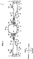
- FIG. 4 is a sectional view taken along line A-A of FIG. 2 .
- FIG. 5 is a partial enlarged sectional view of FIG. 4 . Referring to FIGS. 4 and 5 , a portion, substantially in the Y direction, of the vehicle floor 2 where the mount member 70 and the first floor cross member 14 are provided and its surrounding area will be described.
- the vehicle floor 2 comprises a tunnel panel 40 which constitutes the floor tunnel 50 and a pair of right-and-left bottom face panels 42 which constitute the bottom face portion 3.
- the tunnel panel 40 is provided at a central portion, in the X direction, of the vehicle floor 2 between the right-and-left side sills 4.
- Each of the bottom face panels 42 is provided to interconnect the tunnel panel 40 and the side sill 4.
- the tunnel panel 40 and the bottom face panel 42 can be respectively a pressed part, which is, for example made of steel. It is preferable that the tunnel panel 40 have the higher rigidity and strength than the bottom face panel 42, whereby the rigidity and strength of the floor tunnel 50 can be improved.
- the vehicle floor 2 may further include a pair of upper step portions 51 which particularly are configured to rise inwardly, in the X direction, from the bottom face portion 3 and be continuous to a lower edge portion of the floor tunnel 50.
- the upper step portion 51 particularly is configured to extend substantially in the Y direction along the lower edge portion of the floor tunnel 50 from a forward side of the first floor cross member 14 to a rearward side of the second floor cross member 16.
- a ridgeline L5 can be formed at the upper step portion 51.
- the mount member 70 particularly is fixed to the upper step portion 51.
- the upper step portion 51 which can be integrally formed with the vehicle floor 2, is provided at a boundary area between the bottom face portion 3 and the lower edge portion of the floor tunnel 50, whereby the rigidity is increased.
- the tunnel side reinforcement 81 is provided along the boundary area of the bottom face portion 3 and the lower edge portion of the front tunnel 50.
- the tunnel side reinforcement 81 is located at the position which at least partially overlaps the mount member 70 of the upper step portion 51.
- the tunnel side reinforcement 81 is arranged such as to at least partially overlap the mount member 70 and/or the upper step portion 51.
- the upper step portion 51 particularly comprises a first lateral plate portion 51a which is configured to extend outwardly, in the X direction, from the lower end portion of the floor tunnel 50 and a first slant portion 51b which can be configured to extend obliquely downwardly, substantially in the Z direction, from an outside end portion, in the X direction, of the first lateral plate portion 51a.
- the first slant portion 51b may be configured to extend downwardly, substantially in the Z direction.
- the mount member 70 particularly is fixed to the first lateral plate portion 51a of the upper step portion 51.
- the first lateral plate portion 51a and the first slant portion 51b of the upper step portion 51 particularly are constituted by a part of the tunnel panel 40.
- the tunnel panel 40 may further comprise an extension portion 51c which extends outwardly, in the X direction, from a lower end portion of the first slant portion 51b.
- the extension portion 51c particularly is joined to the bottom face panel 42, for example by welding.
- the upper step portion 51 may be configured by a part of the bottom face panel 42 or a different member from the tunnel panel 40 and the bottom face panel 42.
- the bottom face portion 3 of the vehicle floor 2 particularly comprises a pair of right-and-left middle step portions 52 which can be continuous to an outside portion, in the X direction, of the upper step portion 51, a pair of right-and-left lower step portions 53 which can be continuous to an outside portion, in the X direction, of the middle step portion 52, and/or a joined portion 54 which can be joined to the side sill 4 on the outside, in the X direction, of the lower step portion 53.
- the middle step portion 52 particularly comprises a second lateral plate portion 52a which can be configured to extend in the X direction and a second slant portion 52b which can be configured to extend obliquely outwardly, in the X direction, and downwardly, substantially in the Z direction, from an outside end portion of the second lateral plate portion 52a.
- the middle step portion 52 particularly comprises a third lateral plate portion 52c which can be configured to extend outwardly, in the X direction, from an outside end portion, in the X direction, of the second slant portion 52c and a third slant portion 52d which can be configured to extend obliquely outwardly, in the X direction, and downwardly, substantially in the Z direction, from an outside end portion of the third lateral plate portion 52c.
- the second lateral plate portion 52a of the middle step portion 52 particularly is joined to an upper face of the extension portion 51c of the tunnel panel 40.
- an inside end portion, in the X direction, of the second lateral plate portion 52a of the middle step portion 52 particularly is connected to a lower end portion of the first slant portion 51b of the upper step portion 51 via the extension portion 51c.
- the upper frame member 61 and the lower frame member 62 which constitute the floor frame 12 particularly are provided to face each other, interposing the third lateral plate portion 52c and the third slant portion 52d of the middle step portion 52 therebetween.
- the lower step portion 53 particularly comprises a fourth lateral plate portion 53a which extends outwardly, in the X direction, from a lower end portion of the third slant portion 52d of the middle step portion 52.
- the fourth lateral plate portion 53a of the lower step portion 53 constitutes a lowermost part of the vehicle floor 2.
- the upper frame member 61 and the lower frame member 62 of the floor frame 12 particularly are joined to the third lateral plate portion 52c of the middle step portion 52 and the fourth lateral plate portion 53a of the lower step portion 53 by welding, whereby the members 61, 62 can be fixed to the bottom face panel 42.
- the joined portion 54 particularly is provided to extend upwardly from an outside end portion, in the X direction, of the lower step portion 53.
- the joined portion 54 particularly is joined to a cabin-side face of the side sill inner 5 of the side sill 4, for example by welding.
- the lower step portion 53 particularly is located at a lower level than the joined portion 54 joined to the side sill 4 substantially in the Z direction. Accordingly, a sectional area of the closed cross section formed between the vehicle floor 2 and the first floor cross member 14 particularly is enlarged in an area of the X direction where the lower step portion 53 is provided, so that the rigidity improvement of the first floor cross member 14 is attained.
- the sectional shape of the vehicle floor 2 taken along line A-A of FIG. 2 is not limited to the structure shown in FIGS. 4 and 5 but changeable.
- the middle step portion 52 provided between the upper step portion 51 and the lower step portion 53 may be formed in one stage or three or more stages, or may be omitted.
- the lower step portion 53 can be located at the lower level than the joined portion 54 in the present embodiment
- the fourth lateral plate portion 53a of the lower step portion 53 may be located at a level which at least partially overlaps the joined portion 54 or at a higher level than the joined portion 54.
- the fourth lateral plate portion 53a of the lower step portion 53 particularly is arranged such as to at least partially overlap the joined portion 54 or at a higher level than the joined portion 54.
- the upper face portion 14a of the first floor cross member 14 with the first front-side ridgeline L1 and the first rear-side ridgeline L2 particularly is located at a higher level than the middle step portion 52 and the lower step portion 53 of the vehicle floor 2 and/or also substantially at the same level as the first lateral plate portion 51a of the upper step portion 51.
- the floor frame 12, the first floor cross member 14, and/or the side sill 4 particularly are positioned such that these at least partially overlap substantially in the Z direction.
- the first inside seat bracket 65 particularly is joined to an outside face of the floor tunnel 50, for example, by welding at an inside end portion, in the X direction, thereof.
- an outside end portion, in the X direction, of the first inside seat bracket 65 particularly is jointly fastened with the first floor cross member 14, the first lateral plate portion 51a of the upper step portion 51, and/or the mount member 70.
- the first floor cross member 14 can be connected to the floor tunnel 50 via the first inside seat bracket 65.
- an inside end portion, in the X direction, of the first outside seat bracket 66 particularly is joined to the upper face portion 14a of the first floor cross member 14, for example by welding.
- An outside end portion, in the X direction, of the first outside seat bracket 66 particularly is joined to the inside face of the side sill inner 5 of the side sill 4, for example by welding.
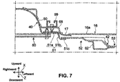
- FIG. 6 is a sectional view taken along line B-B of FIG. 2 .
- FIG. 7 is a partial enlarged sectional view of FIG. 6 . Referring to FIGS. 6 and 7 , a portion, substantially in the Y direction, of the vehicle floor 2 where the tunnel member 80 and the second floor cross member 16 are provided and its surrounding area will be described.
- the cross section of the vehicle floor 2 shown in FIGS. 6 and 7 is similar to the cross section of the vehicle floor 2, specific description of which is omitted here.
- the tunnel member 80 particularly is fixed to the upper step portion 51. More specifically, the tunnel member 80 particularly is fixed to a lower face of the first lateral plate portion 51a of the upper step portion 51 as shown in FIG. 7 .
- the connecting member 17 particularly is joined to the inside end portion, in the X direction, of the second floor cross member 16 as described above.
- the inside end portion, in the X direction, of the connecting member 17 can be fixed to the first lateral plate portion 51a of the upper step portion 51 and the tunnel member 80, whereby the upper step portion 16a of the second floor cross member 16 particularly is connected to the first lateral plate portion 51a of the upper step portion 51.
- the connecting member 17 may be formed integrally with the second floor cross member 16.
- the upper frame member 61 particularly is provided on the forward side, substantially in the Y direction, of the second floor cross member 16 as described above (see FIG. 2 ), the upper frame member 61 which can constitute the floor frame 12 particularly is not provided in the cross section shown in FIGS. 6 and 7 .
- the closed cross section can be formed by the bottom face panel 42 and the lower frame member 62.
- the upper face portion 16a of the second floor cross member 16 with the second front-side ridgeline L3 and the second rear-side ridgeline L4 particularly is located at a higher level than the middle step portion 52 and/or the lower step portion 53 of the vehicle floor 2 and also substantially at the same level as the first lateral plate portion 51a of the upper step portion 51.
- the second inside seat bracket 68 particularly is joined to the outside face of the floor tunnel 50, for example, by welding at an inside end portion, in the X direction, thereof, and connected to the connecting member 17, for example, by welding at an outside end portion, in the X direction, thereof.
- the second floor cross member 16 particularly is connected to the floor tunnel 50 via the second inside seat bracket 68 and/or the connecting member 17.
- an inside end portion, in the X direction, of the second outside seat bracket 69 particularly is joined to the upper face portion 16a of the second floor cross member 16, for example by welding.
- An outside end portion, in the X direction, of the second outside seat bracket 69 particularly is joined to the inside face of the side sill inner 5 of the side sill 4, for example by welding.
- the floor frame 12, the first floor cross member 14, the second floor cross member 16, and/or the side sill 4 particularly are provided such that these at least partially overlap substantially in the Z direction. That is, a frame-shaped structure which can be formed, at the vehicle floor 2, by the floor frame 12 and the side sill 4 which respectively extend substantially in the Y direction and the first floor cross member 14 and the second floor cross member 16 which respectively extend in the X direction particularly is configured such that it is not offset substantially in the Z direction.
- FIG. 8 is a perspective view of the mount member 70 according to the present embodiment.
- FIG. 9 is a side view of the mount member 70 of the present embodiment, when viewed from a right side in the X direction, of the vehicle body. A structure of the mount member 70 will be described referring to FIGS. 8 and 9 .
- the vehicle width direction, the vehicle longitudinal direction, and the vehicle vertical direction in a case where the mount member 70 is attached to the vehicle floor 2 are shown as the X direction, the Y direction, and the Z direction, respectively.
- the mount member 70 is a casting part, which is, for example made of aluminum alloy.
- the mount member 70 comprises a base part 71 which extends in the X direction and a fixation part 72 which is provided at both end portions, in the X direction, of the base part 71.
- the base part 71 is configured to protrude downwardly substantially in the Z direction, which is of a curved shape, when viewed from the Y direction.
- the transmission 24 (shown in FIG. 3 ) is supported at the vehicle floor 2 (shown in FIG. 3 ) via the base part 71 of the mount member 70.
- Each of the fixation parts 72 comprises a first protrusion portion 73 which is provided at a central portion, substantially in the Y direction, of the base part 71, a second protrusion portion 74 which is provided to be forwardly spaced, substantially in the Y direction, apart from the first protrusion portion 73, and a third protrusion portion 75 which is provided to be rearwardly spaced, substantially in the Y direction, apart from the first protrusion portion 73.
- the first protrusion portion 73 is configured to protrude outwardly, in the X direction, from the base part 71.
- the first protrusion portion 73 includes an outside fixation point 73a and an inside fixation point 73b, where the mount member 70 is fixed to the vehicle floor 2.
- the outside fixation point 73a is positioned at an outside end portion, in the X direction, of the first protrusion portion 73.
- the outside fixation point 73a has a through (penetration) hole where the first protrusion portion 73 is inserted substantially in the Z direction.
- the inside fixation point 73b is provided to be spaced, in the X direction, apart from the outside fixation point 73a.
- a through hole where the first protrusion portion 73 is inserted substantially in the Z direction is formed at the inside fixation point 73b.
- the inside fixation point 73b is located substantially at the same level, substantially in the Z direction, as the outside fixation point 73a.
- the second protrusion portion 74 is configured to protrude outwardly, in the X direction, and forwardly, substantially in the Y direction, from the base part 71.
- An outside end portion, in the X direction, of the second protrusion portion 74 has a fixation point 74a where the mount member 70 is fixed to the vehicle floor 2.
- This fixation point 74a has a through hole where the second protrusion portion 74 is inserted substantially in the Z direction.
- the third protrusion portion 75 is configured to protrude outwardly, in the X direction, and rearwardly, substantially in the Y direction, from the base part 71.
- An outside end portion, in the X direction, of the third protrusion portion 75 has a fixation point 75a where the mount member 70 is fixed to the vehicle floor 2.
- This fixation point 75a has a through hole where the third protrusion portion 75 is inserted substantially in the Z direction.
- the outside fixation point 73a of the first protrusion portion 73, the fixation point 74a of the second protrusion portion 74, and the fixation point 75a of the third protrusion portion 75 are located at different levels, substantially in the Z direction, from each other in a state where the mount member 70 is attached to the vehicle floor 2 (shown in FIG. 3 ).
- the outside fixation point 73a of the first protrusion portion 73 is located a higher level than the fixation point 74a of the second protrusion portion 74 and the fixation point 75a of the third protrusion portion 75.
- the inside fixation point 73b shown in FIG.
- the first protrusion portion 73 is located substantially at the same level, substantially in the Z direction, as the outside fixation point 73a as described above, this point 73b is provided on an upward side, substantially in the Z direction, of the fixation point 74a of the second protrusion portion 74 and the fixation point 75a of the third protrusion portion 75.
- fixation point 74a of the second protrusion portion 74 and the fixation point 75a of the third fixation portion 75 are located substantially at the same position substantially in the Z direction.
- FIG. 10 is a perspective view showing a surrounding area of the mount member 70.
- FIG. 11 is an exploded perspective view showing the surrounding area of the mount member 70. An attachment structure of the mount member 70 to the vehicle floor 2 will be described referring to FIGS. 10 and 11 .
- the mount member 70 is fixed to the vehicle floor 2 at plural (four, in the present embodiment) fixation positions P1, P2, P3, P4 at both sides, in the X direction, thereof.
- Plural bolts are used for attachment of the mount member 70 to the vehicle floor 2.
- the mount member 70 is attached to the vehicle floor directly or via the tunnel side reinforcements 81.
- the first lateral plate portion 51a of the upper step portion 51 of the vehicle floor 2 are formed through holes which respectively correspond to the outside fixation portion 73a and the inside fixation point 73b of the first protrusion portion 73 of the mount member 70. Further, a through hole which corresponds to the fixation portion 74a of the second protrusion portion 74 of the mount member 70 and a through hole which corresponds to the fixation portion 75a of the third protrusion portion 75 of the mount member 70 are formed at the first lateral plate portion 51a of the upper step portion 51 of the vehicle floor 2.
- the tunnel side reinforcement 81 is attached to the first lateral plate portion 51a of the upper step portion 51 as described above.
- the tunnel side reinforcement 81 which extends substantially in the Y direction, comprises a first attachment portion 81a which corresponds to the first protrusion portion 73 of the mount member 70, a second attachment portion 81b which corresponds to the second protrusion portion 74 of the mount member 70, and a third attachment portion 81c which corresponds to the third protrusion portion 75.
- the first attachment portion 81a of the tunnel side reinforcement 81 is a flat-plate shaped part which extends along the first lateral plate portion 51a of the upper step portion 51, and a through hole (not illustrated) is formed at a position which corresponds to the inside fixation point 73b of the first protrusion portion 73.
- the second attachment portion 81b of the tunnel side reinforcement 81 is configured to protrude downwardly, substantially in the Z direction, so as to form a closed cross section together with the first lateral plate portion 51a of the upper step portion 51.
- a through hole (not illustrated) is formed at the second attachment portion 81b of the tunnel side reinforcement 81 at a position corresponding to the fixation point 74a of the second protrusion portion 74.
- the third attachment portion 81c of the tunnel side reinforcement 81 is configured to protrude downwardly, substantially in the Z direction, so as to form a closed cross section together with the first lateral plate portion 51a of the upper step portion 51.
- a through hole (not illustrated) is formed at the third attachment portion 81c of the tunnel side reinforcement 81 at a position corresponding to the fixation point 75a of the third protrusion portion 75.
- the mount member 70 is fixed to the first lateral plate portion 51a of the upper step portion 51 at the outside fixation point 73a of the first protrusion portion 73 (the fixation position P1 of FIG. 10 ) and also fixed to the first attachment portion 81a of the tunnel side reinforcement 81 at the inside fixation point 73b (shown in FIG. 8 ) of the first protrusion portion 73 (the fixation position P4 of FIG. 10 ). Further, the mount member 70 is fixed to the second lateral plate portion 81b of the tunnel side reinforcement 81 at the fixation point 74a of the second protrusion portion 74 (the fixation position P2 of FIG.
- the second attachment portion 81b and the third attachment portion 81c of the tunnel side reinforcement 81 are positioned on the downward side, substantially in the Z direction, of the first lateral plate portion 51a of the upper step portion 51.
- fixation positions P1, P2, P3, P4 of the mount member 70 to the vehicle floor 2 are set at different positions, substantially in the Z direction, from each other.
- the fixation position P1 which is located at a center, substantially in the Y direction, of three positions is provided at the first lateral plate portion 51a of the upper step portion 51, and the other two fixation positions P2, P3 are provided at the tunnel side reinforcement 81. That is, the central fixation position P1, substantially in the Y direction, is provided to at least partially overlap the upper face portion 14a of the first floor cross member 14 substantially in the Z direction (see FIG. 4 ).
- the fixation part 72 of the mount member 70 is positioned in a range of a height, substantially in the Z direction, of the first floor cross member 14. That is, the four fixation positions P1, P2, P3, P4 of the mount member 70 to vehicle floor 2 are positioned in the range of the height, substantially in the Z direction, of the first floor cross member 14.
- the tunnel member 80 is a hollow extruded one which is configured to extend in the X direction and have a closed cross section in the cross section perpendicular to the X direction.
- the tunnel member 80 is made of aluminum alloy, for example.
- the tunnel member 80 is fixed to the first lateral plate portions 51a of the upper step portions 51 at both end portion, in the X direction, thereof.
- the tunnel member 80 is located in a rage of a height, substantially in the Z direction, of the second floor cross member 16.
- the tunnel member 80 is positioned substantially in the Z direction so that it at least partially overlaps the upper face portion 16a of the second floor cross member 16.
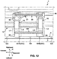
- FIG. 12 is a plan view showing a surrounding area of the inside seat rail 99 and the outside seat rail 100. Referring to FIGS. 1 , 4 , 6 and 12 , a structure of the side sill 4 around the inside seat rail 99 will be described.
- the side sill 4 of the present embodiment particularly has plural (five in the present embodiment) gussets 101 which particularly are provided inside the side sill inner 5.
- the gusset 101 particularly is a flat-plate shaped member which extends along a plane crossing the Y direction, and particularly is fixed to the side sill inner 5, for example by welding. As apparently shown in FIG. 12 , a gusset 101A particularly is located at a position which at least partially overlaps the first floor cross member 14 substantially in the Y direction. In other words, the gusset 101A can be arranged such as to at least partially overlap the first floor cross member 14 substantially in the Y direction. Specifically, the gusset 101A particularly is provided on the side of the second floor cross member 16 of a center of the first floor cross member 14 substantially in the Y direction, particularly at a position which at least partially overlaps the first rear-side ridgeline L2.
- the gusset 101A particularly is arranged on the side of the second floor cross member 16 of a center of the first floor cross member 14 in the Y direction such as to at least partially overlap the first rear-side ridgeline L2.
- a gusset 101B is located at a position which at least partially overlaps the second floor cross member 16 substantially in the Y direction.
- the gusset 101B is provided on the side of the first floor cross member 14 of a center of the second floor cross member 16 substantially in the Y direction, particularly at a position which at least partially overlaps the second front-side ridgeline L3.
- the gusset 101B particularly is arranged on the side of the first floor cross member 14 of a center of the second floor cross member 16 substantially in the Y direction such as to at least partially overlap the second front-side ridgeline L3.
- the gusset 101 particularly is provided such that it at least partially overlaps the first floor cross member 14 and/or the floor frame 12 substantially in the Z direction.
- the gusset 101 particularly is provided such that it at least partially overlaps the second floor cross member 16 and/or the floor frame 12 substantially in the Z direction.
- the substantially ladder-shaped structure particularly is formed by means of the first floor cross members 14 and the second floor cross member 16 which respectively extend in the X direction and the upper step portions 51, the floor frames 12, and/or the side sills 4 which respectively extend substantially in the Y direction.
- the first inside seat bracket 65, the outside seat bracket 66, the second inside seat bracket 68, and/or the second outside seat bracket 69 particularly are fixed to the above-described substantially ladder-shaped structure. That is, the inside seat rail 99 and the outside seat rail 100 can be fixed to the substantially ladder-shaped structure.
- the frame structure particularly is formed at the vehicle floor 2 by means of the side sill 4 and the floor frame 12 which respectively extend substantially in the Y direction and having the closed cross section and the first floor cross member 14 and the second floor cross member 16 which respectively extend in the X direction and having the closed cross section.
- the members of this frame structure particularly are configured not to be offset substantially in the Z direction. Accordingly, the support rigidity of the vehicle floor 2 for attaching the seat can be properly improved, and also a sense of unity between the vehicle body and the seat can be improved by fixing the first inside seat bracket 65, the second inside seat bracket 68, and/or the second outside seat bracket 69 for attaching the seat to the frame structure.
- the gusset 101 extending along the plane crossing the Y direction particularly is provided at the side sill 4, the strength, substantially in the Z direction and in the X direction, of the side sill 4 can be improved.
- the gusset 101A particularly is located at the position at least partially overlapping the first floor cross member 14 substantially in the Y direction and/or the gusset 101B particularly is located at the position at least partially overlapping the second floor cross member 16 substantially in the Y direction.
- the gusset 101A particularly is particularly is arranged such as to at least partially overlap the first floor cross member 14 substantially in the Y direction and/or the gusset 101B particularly is arranged such as to least partially overlap the second floor cross member 16 substantially in the Y direction. Accordingly, the rigidity of the frame structure formed by means of the side sill 4, the floor frame 12, the first floor cross member 14, and/or the second floor cross member 16 can be improved.
- the gusset 101A particularly is located at the position which at least partially overlaps the first floor cross member 14 substantially in the Y direction, and also located at the position which is offset, toward the second floor cross member 16, from a center, substantially in the Y direction, of the first floor cross member 14.
- the gusset 101A can be arranged such as to at least partially overlap the first floor cross member 14 substantially in the Y direction and also arranged such as to be positioned offset, toward the second floor cross member 16, from a center, substantially in the Y direction, of the first floor cross member 14.
- a load applied from the seat can be effectively transmitted to the first floor cross member 14 by way of the gusset 101A because the seat is generally arranged between the first floor cross member 14 and the second floor cross member 16 substantially in the Y direction.
- the gusset 101B is located at the position which at least partially overlaps the second floor cross member 16 substantially in the Y direction, and also located at the position which is offset, toward the first floor cross member 14, from a center, substantially in the Y direction, of the second floor cross member 16.
- the gusset 101B can be arranged such as to at least partially overlap the second floor cross member 16 in the Y direction and also arranged such as to be offset, toward the first floor cross member 14, from a center, substantially in the Y direction, of the second floor cross member 16.
- the load applied from the seat can be effectively transmitted to the second floor cross member 16 by way of the gusset 101A because the seat is generally arranged between the first floor cross member 14 and the second floor cross member 16 substantially in the Y direction.
- the frame structure particularly is formed at the vehicle floor 2 by means of the side sill 4, the floor frame 12, the first floor cross member 14, and/or the second floor cross member 16.
- the first outside seat bracket 66 particularly is fixed to the side sill 4 and/or the first floor cross member 14, and can be fixed to a corner portion which particularly is formed by the side sill 4 and the first floor cross member 14. Accordingly, the support rigidity of the vehicle floor 2 for attaching the seat can be properly improved.
- the second outside seat bracket 69 particularly is fixed to the side sill 4 and the second floor cross member 16, and can be fixed to a corner portion which particularly is formed by the side sill 4 and the second floor cross member 16. Accordingly, the support rigidity of the vehicle floor 2 for attaching the seat can be properly improved.
- the substantially ladder-shaped structure particularly is formed at the vehicle floor 2 by means of the side sill 4, the upper step portion 51, and/or the floor frame 12 which respectively extend substantially in the Y direction and the first floor cross member 14 and the second floor cross member 16 which respectively extend in the X direction.
- the first inside seat bracket 65 particularly is fixed to the upper step portion 51 and the first floor cross member 14, and therefore this bracket 65 is fixed to a corner portion which is formed by the upper step portion 51 and the first floor cross member 14. Accordingly, the support rigidity of the vehicle floor 2 for attaching the seat can be properly improved.
- the second inside seat bracket 68 particularly is fixed to the upper step portion 51 and the second floor cross member 16, and therefore this bracket 68 is fixed to the corner portion which is formed by the upper step portion 51 and the second floor cross member 16. Accordingly, the support rigidity of the vehicle floor 2 for attaching the seat can be properly improved.
- the upper step portion 51 can be configured to rise substantially upwardly particularly is provided between the bottom face portion 3 of the vehicle floor 2 and the floor tunnel 50, the rigidity of the boundary area between the bottom face portion 3 of the vehicle floor 2 and the floor tunnel 50 can be improved. Since the first inside seat bracket 65 and the second inside seat bracket 68 particularly are fixed to the upper step portion 51, the support rigidity of the vehicle floor 2 for attaching the seat can be properly improved.
- the inside seat rail 99 of the modified example particularly is fastened together with the first inside seat bracket 65, the upper step portion 51, and/or the mount member 70.
- a tall nut (spacer) 91 can be provided to penetrate the mount member 70 and/or the first lateral plate portion 51a of the upper step portion 51, and a bolt 92 which is provided to penetrate the first inside seat bracket 65 and/or the inside seat rail 99 is screwed to the tall nut 91.
- the inside seat rail 99 of the modified example particularly is fastened together with the second inside seat bracket 68, the upper step portion 51, and/or the connecting member 17.
- a tall nut (spacer) 93 particularly is provided to penetrate the connecting member 17 and/or the first lateral plate portion 51a of the upper step portion 51, and a bolt 94 which can be provided to penetrate the second inside seat bracket 68 and/or the inside seat rail 99 is screwed to the tall nut 93.
- the strength of the first inside seat bracket 65 against compression which particularly is generated substantially in the Z direction by the load applied from the inside seat rail 99 can be improved.
- the second inside seat bracket 68 and the first lateral plate portion 51a of the upper step portion 51 are interconnected by the tall nut 93, the strength of the second inside seat bracket 68 against compression which particularly is generated substantially in the Z direction by the load applied from the inside seat rail 99 can be improved.
- tall nut 91 can be used as the spacer which is provided between the vehicle floor 2 and the first inside seat bracket 65 according to the above-described modified example, a collar having no screw hole may be applied instead of the spacer in the present invention.
Landscapes
- Engineering & Computer Science (AREA)
- Transportation (AREA)
- Mechanical Engineering (AREA)
- Chemical & Material Sciences (AREA)
- Combustion & Propulsion (AREA)
- Aviation & Aerospace Engineering (AREA)
- Body Structure For Vehicles (AREA)
Abstract
Description
- The present invention relates to a lower vehicle-body structure.
- A floor cross member extending in a vehicle with direction and a floor frame extending substantially in a vehicle longitudinal direction are provided on an upper face of a vehicle floor of an automotive vehicle for improving the vehicle-body rigidity or the like. Further, a seat rail to guide a slide move of a seat is generally provided on the vehicle floor such that it extends substantially in the vehicle longitudinal direction. In general, this seat rail is fixed to a vehicle body via brackets having the high rigidity. Thereby, the heavy seat can be stably supported.
- In order to secure the attachment rigidity of the seat rail, as disclosed in Japanese Patent Laid-Open Publication No.
2010-228482 - However, in a structure disclosed in the above-described patent document, there is still room for improvement on the support rigidity of the vehicle body for properly supporting the seat rail from a viewpoint of a sense of unity between the vehicle body and the seat.
- Accordingly, an object of the present invention is to provide a lower vehicle-body structure which can properly improve the support rigidity of the vehicle floor for supporting the seat rail.
- This object is solved by the lower vehicle-body structure according to the present invention of the independent claim. Preferred embodiments of the present invention are subject of the other dependent claims.
- An aspect relates to a lower vehicle-body structure which comprises a vehicle floor comprising a bottom face portion, a first floor cross member extending in a vehicle width direction and provided on the bottom face portion of the vehicle floor, the first floor cross member forming a closed cross section between the bottom face portion of the vehicle floor and the first floor cross member in a cross section perpendicular to the vehicle width direction, a second floor cross member extending in the vehicle width direction and provided on the bottom face portion of the vehicle floor, the second floor cross member forming a closed cross section between the bottom face portion of the vehicle floor and the second floor cross member in a cross section perpendicular to the vehicle width direction, the second floor cross member being spaced, substantially in a vehicle longitudinal direction, apart from the first floor cross member, a side sill extending substantially in the vehicle longitudinal direction and provided at an end portion, in the vehicle width direction, of the bottom face portion of the vehicle floor, the side sill forming a closed cross section between the bottom face portion of the vehicle floor and the side sill in a cross section perpendicular to the vehicle longitudinal direction, a floor frame extending substantially in the vehicle longitudinal direction and provided on the bottom face portion of the vehicle floor at a position which is located on an inward side, in the vehicle width direction, of the side sill, the floor frame forming a closed cross section between the bottom face portion of the vehicle floor and the floor frame in a cross section perpendicular to the vehicle longitudinal direction, and an attaching member attaching a seat to a vehicle body, wherein the first floor cross member, the second floor cross member, the side sill, and/or the floor frame are located at respective positions which overlap each other at least partially substantially in a vehicle vertical direction, and the attaching member is fixed to the side sill, the first floor cross member, and/or the second floor cross member.
- In this aspect, in other words, the first floor cross member, the second floor cross member, the side sill, and/or the floor frame are arranged at respective positions such as to at least partially overlap each other substantially in the vehicle vertical direction and the attaching member is fixed to the side sill, the first floor cross member, and/or the second floor cross member.
- According to this aspect, a frame structure is formed at the vehicle floor particularly by means of the side sill and the floor frame which respectively extend substantially in the vehicle longitudinal direction and having the closed cross section and the first floor cross member and the second floor cross member which respectively extend in the vehicle width direction and having the closed cross section. Further, the members of this frame structure particularly are configured not to be offset substantially in the vehicle vertical direction. Accordingly, the support rigidity of the vehicle floor for attaching the seat can be properly improved, and also a sense of unity between the vehicle body and the seat can be improved by fixing the attaching member for attaching the seat to the frame structure.
- Further, the side sill particularly includes a reinforcing plate which extends along a plane crossing the vehicle longitudinal direction inside the closed cross section of the side sill, and the reinforcing plate can be located at a position which at least partially overlaps at least one of the first floor cross member and the second floor cross member substantially in the vehicle longitudinal direction. In other words, the reinforcing plate particularly is arranged such as to at least partially overlap at least one of the first floor cross member and the second floor cross member substantially in the vehicle longitudinal direction.
- Since the reinforcing plate extending along the plane crossing the vehicle longitudinal direction particularly is provided at the side sill, the strength, in the vehicle vertical direction and in the vehicle width direction, of the side sill can be improved. Moreover, since the reinforcing plate particularly is located at the position at least partially overlapping at least one of the first floor cross member and the second floor cross member substantially in the vehicle longitudinal direction, the rigidity of the frame structure formed by means of the side sill, the floor frame, the first floor cross member, and/or the second floor cross member can be improved.
- Further, the reinforcing plate particularly is located at a position which at least partially overlaps the first floor cross member substantially in the vehicle longitudinal direction, and the reinforcing plate particularly is located at a position which is offset, toward the second floor cross member, from a center, substantially in the vehicle longitudinal direction, of the first floor cross member. In other words, the reinforcing plate particularly is arranged such as to at least partially overlap the first floor cross member substantially in the vehicle longitudinal direction and the reinforcing plate particularly is arranged such as to be positioned offset, toward the second floor cross member, from a center, substantially in the vehicle longitudinal direction, of the first floor cross member.
- With this configuration, a load applied from the seat can be effectively transmitted to the first floor cross member by way of the reinforcing plate because the seat is generally arranged between the first floor cross member and the second floor cross member substantially in the vehicle longitudinal direction.
- Further, the reinforcing plate particularly is located at a position which at least partially overlaps the second floor cross member substantially in the vehicle longitudinal direction, and the reinforcing plate particularly is located at a position which is offset, toward the first floor cross member, from a center, substantially in the vehicle longitudinal direction, of the second floor cross member. In other words, the reinforcing plate particularly is arranged such as to at least partially overlap the second floor cross member substantially in the vehicle longitudinal direction and the reinforcing plate particularly is arranged such as to be positioned offset, toward the first floor cross member, from a center, substantially in the vehicle longitudinal direction, of the second floor cross member.
- With this configuration, a load applied from the seat can be effectively transmitted to the second floor cross member by way of the reinforcing plate because the seat is generally arranged between the first floor cross member and the second floor cross member substantially in the vehicle longitudinal direction.
- The reinforcing plate particularly is formed as a gusset.
- In particular, the attaching member can be fixed to the side sill and any one of the first floor cross member and the second floor cross member. In other words, the attaching member can be fixed to the side sill and at least one of the first floor cross members and/or the second floor cross members.
- With this configuration, since the attaching member can be fixed to a corner portion which particularly is formed by the side sill and any one of the first floor cross member and the second floor cross member, the support rigidity of the vehicle floor for attaching the seat can be properly improved.
- The vehicle floor particularly comprises a floor tunnel which is configured to protrude substantially upwardly from the bottom face portion and extend substantially in the vehicle longitudinal direction and an upper step portion which particularly is configured to rise substantially upwardly toward the floor tunnel from the bottom face portion in the vehicle width direction. Further, the attaching member particularly is attached to the upper step portion and any one of the first floor cross member and the second floor cross member. In other words, the attaching member particularly is attached to the upper step portion and at least one of the first floor cross members and/or the second floor cross members.
- With this configuration, a substantially ladder-shaped structure particularly is formed at the vehicle floor by means of the side sill, the upper step portion, and/or the floor frame which respectively extend substantially in the vehicle longitudinal direction and the first floor cross member and/or the second floor cross member which respectively extend in the vehicle width direction. Since the attaching member can be fixed to a corner portion which particularly is formed by the upper step portion and any one of the first floor cross member and the second floor cross member, the support rigidity of the vehicle floor for attaching the seat can be properly improved.
- Moreover, since the upper step portion particularly configured to rise substantially upwardly can be provided between the vehicle floor and the floor tunnel, the rigidity of a boundary area between the vehicle floor and the floor tunnel can be improved. Since the attaching member particularly is fixed to the upper step portion, the support rigidity of the vehicle floor for attaching the seat can be properly improved.
- Further, the lower vehicle-body structure particularly further comprises a spacer which can be interposed between the attaching member and the upper step portion and interconnects the attaching member and the upper step portion.
- With this configuration, since the spacer can be provided between the attaching member for attaching the seat and the upper step portion, the strength of the attaching member against compression which is generated in the vehicle vertical direction by the load applied from the seat can be improved.
- Other features, aspects, and advantages of the present invention will become apparent from the following description which refers to the accompanying drawings.
-
FIG. 1 is a perspective view showing a lower vehicle-body structure according to an embodiment of the present invention. -
FIG. 2 is a plan view showing the lower vehicle-body structure according to the embodiment. -
FIG. 3 is a bottom view showing the lower vehicle-body structure according to the embodiment. -
FIG. 4 is a sectional view taken along line A-A ofFIG. 2 . -
FIG. 5 is a partial enlarged sectional view ofFIG. 4 . -
FIG. 6 is a sectional view taken along line B-B ofFIG. 2 . -
FIG. 7 is a partial enlarged sectional view ofFIG. 6 . -
FIG. 8 is a perspective view of a mount member according to the embodiment. -
FIG. 9 is a side view of the mount member according to the embodiment. -
FIG. 10 is a perspective view showing a surrounding area of the mount member according to the embodiment. -
FIG. 11 is an exploded perspective view showing the surrounding area of the mount member according to the embodiment. -
FIG. 12 is a plan view showing a surrounding area of a seat rail according to the embodiment. -
FIG. 13 is a partial enlarged sectional view of a modified example of the embodiment, which is similar toFIG. 5 . -
FIG. 14 is a partial enlarged sectional view of the modified example of the embodiment, which is similar toFIG. 7 . - Hereafter, an embodiment of the present invention will be described referring to the attached drawings.
-
FIG. 1 is a perspective view showing a lower vehicle-body structure according to the embodiment of the present invention.FIG. 2 is a plan view showing the lower vehicle-body structure.FIG. 3 is a bottom view showing the lower vehicle-body structure. In the following description, a vehicle width direction, a vehicle longitudinal direction, and a vehicle vertical direction of an automotive vehicle 1 which is provided with the lower vehicle-body structure according to the present embodiment are respectively referred to as an X direction, a Y direction, and a Z direction. - Referring to
FIG. 1 , the automotive vehicle 1 provided with the lower vehicle-body structure according to the present embodiment comprises avehicle floor 2 which constitutes a floor face of a space of a cabin, a pair ofside sills 4 which extend substantially in the Y direction along both-side portions, in the X direction, of thevehicle floor 2, and adash panel 10 which is provided in front of thevehicle floor 2. - Each of the
side sills 4 comprises a side sill inner 5 and a side sill outer (not illustrated). The side sill inner 5 is configured to have a hat-shaped cross section which is opened to an outward side in the X direction in a cross section perpendicular to the Y direction. The side sill outer is configured to have a hat-shaped cross section which is opened to an inward side in the X direction in the cross section perpendicular to the Y direction. The side sill inner 5 and the side sill outer are joined together such that a closed cross section which is continuous substantially in the Y direction is formed therebetween. - The automotive vehicle 1 further comprises a pair of
hinge pillars 11 which rise from respective front end portions of the right-and-left side sills 4 and extend substantially in the Z direction, and thedash panel 10 is provided between the pair ofhinge pillars 11. A cabin space and an engine are partitioned from each other substantially in the Y direction by thedash panel 10. - The
vehicle floor 2 comprises abottom face portion 3 and afloor tunnel 50 which is configured to protrude upwardly, substantially in the Z direction, from thebottom face portion 3 and extend substantially in the Y direction. Thefloor tunnel 50 is provided to extend substantially in the Y direction at a central portion, in the X direction, of thevehicle floor 2. A shape of a cross section of thefloor tunnel 50, when viewed from the Y direction, is U-shaped which is opened to a downward side of the Z direction. - A
opening portion 50a for insertion of a shift lever (not illustrated) is formed at an upper face portion of thefloor tunnel 50. A pair of reinforcingmembers 8 which are configured to extend substantially in the Y direction are joined to both-side portions, in the X direction, of the upper face portion of thefloor tunnel 50 by welding, for example, whereby the rigidity of thefloor tunnel 50 is increased. - A pair of right-and-left floor frames 12 which extend substantially in the Y direction can be joined to the
bottom face portion 3 of thevehicle floor 2. Each of the floor frames 12 particularly is provided between thefloor tunnel 50 and theside sill 4 in the X direction. In other words, each of the floor frames 12 particularly is provided on an inward side, in the X direction, of theside sill 4. Thefloor frame 12 particularly is connected to a front end portion of theside sill 4 via a torque box 22 (shown inFIG. 3 ). - The
floor frame 12 particularly comprises anupper frame member 61 which can be joined to an upper face of thevehicle floor 2, for example by welding, and alower frame member 62 which particularly is joined to a lower face of thevehicle floor 2, for example by welding. Theupper frame member 61 and thelower frame member 62 are provided to face each other, interposing thevehicle floor 2 therebetween. Theupper frame member 61 and thelower frame member 62 are provided to extend substantially in the Y direction, respectively. Thelower frame member 62 and thebottom face portion 3 of thevehicle floor 2 jointly form a closed cross section which is continuous substantially in the Y direction. Referring toFIG. 2 as well, theupper frame member 61 of the present embodiment particularly is provided between a secondfloor cross member 16, which will be described later, and thedash panel 10 substantially in the Y direction. In other words, theupper frame member 61 particularly is not provided on a rearward side, substantially in the Y direction, of the secondfloor cross member 16. - Referring to
FIGS. 1 and2 , a pair of right-and-leftfirst cross members 14 and a pair of right-and-left secondfloor cross members 16 particularly are joined to the upper face of thebottom face portion 3 of thevehicle floor 2 as floor cross members extending in the X direction, respectively. The secondfloor cross members 16 are provided to be spaced apart, rearwardly substantially in the Y direction, from the firstfloor cross members 14. Aninside seat rail 99 and anoutside seat rail 100 can be provided between the firstfloor cross member 14 and the secondfloor cross member 16. - The first
floor cross member 14 particularly is provided to extend between thefloor tunnel 50 and theside sill 4. In other words, the right-and-left firstfloor cross members 14 particularly are provided on both sides, in the X direction, of thefloor tunnel 50. These bothcross members 14 can be arranged substantially at the same position substantially in the Y direction. - The first
floor cross member 14 can be a pressed part which is, for example, made of steel and can be configured to have a hat-shaped cross section which is opened downwardly in a cross section perpendicular to the X direction. The firstfloor cross member 14 and thevehicle floor 2 can jointly form a closed cross section which particularly is continuous in the X direction. The firstfloor cross member 14 particularly includes anupper face portion 14a which substantially upwardly can face thebottom face portion 3 of thevehicle floor 2; in other words, anupper face portion 14a of the firstfloor cross member 14 particularly is arranged distanced from thebottom face portion 3 of thevehicle floor 2 and facing thebottom face portion 3. - The
upper face portion 14a of the firstfloor cross member 14 particularly is provided to extend in the X direction. As shown inFIG. 2 , a first front-side ridgeline L1 which extends in the X direction particularly is formed at a front edge portion of theupper face portion 14a, and a first rear-side ridgeline L2 which extends in the X direction particularly is formed at a rear edge portion of theupper face portion 14a. - Referring to
FIGS. 1 and2 , a first inside seat bracket (attaching member) 65 to support theinside seat rail 99 particularly is joined to an inside end portion, in the X direction, of the firstfloor cross member 14. The firstfloor cross member 14 particularly is connected to thefloor tunnel 50 via the firstinside seat bracket 65. Further, a first outside seat bracket (attaching member) 66 can be joined to an outside end portion, in the X direction, of the firstfloor cross member 14. The firstfloor cross member 14 can be connected to theside sill 5 via the firstoutside seat bracket 66. The firstinside seat bracket 65 and the firstoutside seat bracket 66 can be respectively a pressed part, which is, for example made of steel. - The second
floor cross member 16 particularly is provided to extend between thefloor tunnel 50 and theside sill 4. In other words, the right-and-left firstfloor cross members 16 are provided on both sides, in the X direction, of thefloor tunnel 50. These bothcross members 16 are arranged substantially at the same position substantially in the Y direction. - The second
floor cross member 16 can be a pressed part which is, for example, made of steel can be configured to have a hat-shaped cross section which is opened downwardly in a cross section perpendicular to the X direction. The secondfloor cross member 16 and thevehicle floor 2 can jointly form a closed cross section which particularly is continuous in the X direction. The secondfloor cross member 16 particularly includes anupper face portion 16a which substantially upwardly can face thebottom face portion 3 of thevehicle floor 2; in other words, anupper face portion 16a of the secondfloor cross member 16 can be arranged distanced from thebottom face portion 3 of thevehicle floor 2 and facing thebottom face portion 3. - The
upper face portion 16a of the secondfloor cross member 16 particularly is provided to extend in the X direction. As shown inFIG. 2 , a second front-side ridgeline L3 which extends in the X direction can be formed at a front edge portion of theupper face portion 16a, and a second rear-side ridgeline L4 which extends in the X direction is formed at a rear edge portion of theupper face portion 16a. - A connecting
member 17 particularly is joined to an inside end portion, in the X direction, of the secondfloor cross member 16, for example by welding. The connectingmember 17 can be a pressed part, which is, for example, made of steel and can be configured to have a hat-shaped cross section opened downwardly in the cross section perpendicular to the X direction. The connectingmember 17 and thevehicle floor 2 can jointly form a closed cross section which particularly is continuous in the X direction. Further, the connectingmember 17 particularly includes an upper face portion which extends in the X direction, and two ridgelines which particularly are respectively continuous to the second front-side ridgeline L3 and the second rear-side ridgeline L4 of the secondfloor cross member 16 can be formed at this upper face portion. Herein, the connectingmember 17 may be formed integrally with the secondfloor cross member 16. - As shown in
FIG. 2 , a frame structure can be formed at thevehicle floor 2 by means of the firstfloor cross members 14 and the secondfloor cross members 16 which extend in the X direction and the floor frames 12 and theside sills 4 which extend substantially in the Y direction. - A second inside seat bracket (attaching member) 68 to particularly support the
inside seat rail 99 can be joined to the connectingmember 17, which particularly is joined to the inside end portion, in the X direction, of the secondfloor cross member 16. The secondfloor cross member 16 particularly is connected to thefloor tunnel 50 via the second insideseat bracket 68 and/or the connectingmember 17. Further, a second outside seat bracket (attaching member) 69 particularly is joined to an outside end portion, in the X direction, of the secondfloor cross member 16. The secondfloor cross member 16 particularly is connected to the side sill inner 5 via the secondoutside seat bracket 69. The secondinside seat bracket 68 and the secondoutside seat bracket 69 can be respectively a pressed part, which is, for example made of steel. - A pair of inside seat rails 99 are provided at both sides (right side and left side), in the X direction, of the
floor tunnel 50. Likewise, a pair of outside seat rails 100 are provided at both sides (right side and left side), in the X direction, of thefloor tunnel 50. A pair of front seats (not illustrated) which are provided on the right-and-left sides of thefloor tunnel 50 are supported at the inside seat rails 99 and the outside seat rails 100 from a downward side so as to slide substantially in the Y direction. Each of theinside seat rail 99 and each of the outside seat rails 100 are provided to be spaced apart from each other in the X direction and extend substantially in the Y direction. Theinside seat rail 99 and theoutside seat rail 100 are respectively a pressed part made of steel, for example, and configured to have a roughly C-shaped cross section which is opened upwardly in the cross section perpendicular to the Y direction. - The
inside seat rail 99 particularly is fixed to the firstinside seat bracket 65 at its front end portion and fixed to the secondinside seat bracket 68 at its rear end portion. Theoutside seat rail 100 particularly is fixed to the firstoutside seat bracket 66 at its front end portion and fixed to the secondoutside seat bracket 69 at its rear end portion. - Further, a pair of right-and-left oblique frames 18 are joined to the
upper face portion 3 of thevehicle floor 2 by welding, for example. Thisoblique frame 18 is provided to extend obliquely inwardly and rearwardly in front of the firstfloor cross member 14. Theoblique frame 18 is provided to interconnect thefloor frame 12 and theside sill 4. A connection portion of theoblique frame 18 to theside sill 4 is provided to at least partially overlap the hinge pillar substantially in the Y direction. Theoblique frame 18 is configured to have a hat-shaped cross section opened downwardly in a cross section which is perpendicular to a longitudinal direction of theoblique frame 18, and theoblique frame 18 and thevehicle floor 2 jointly form a closed cross section which is continuous in the longitudinal direction of theoblique frame 18. - Referring to
FIG. 3 , amount member 70 and atunnel member 80 as connecting members are joined to the lower face of thevehicle floor 2. Themount member 70 is provided to extend in the X direction and located at a position which corresponds to the firstfloor cross member 14 substantially in the Y direction. Thetunnel member 80 is provided to extend in the X direction and located at a position which corresponds to the secondfloor cross member 16 substantially in the Y direction. - Further, a substantially ladder-shaped structure particularly is formed at the
vehicle floor 2 by means of the firstfloor cross members 14, the secondfloor cross member 16, themount member 70 and/or thetunnel member 80 which respectively extend in the X direction, and a pair of an upper step portions 51 (described later), a pair of floor frames 12 and/or a pair ofside sills 4 which respectively extend substantially in the Y direction. This substantially ladder-shaped structure particularly is configured to extend in the X direction across thefloor tunnel 50. - Herein, as shown in
FIG. 3 , a pair of tunnel side reinforcements (reinforcing member) 81 which extend substantially in the Y direction particularly are provided at the lower face of thevehicle floor 2. Each of thetunnel side reinforcements 81 and thevehicle floor 2 jointly form a closed cross section. Each of thetunnel side reinforcements 81 is located at a position which at least partially overlaps themount member 70 substantially in the Y direction. In other words, at least one of thetunnel side reinforcements 81 particularly is arranged such as to at least partially overlap themount member 70 at least partially substantially in the Y direction. - The automotive vehicle 1 provided with the lower vehicle-body structure of the present embodiment is a FR type of automotive vehicle equipped with a longitudinally-disposed type of powertrain, for example. The powertrain of the present lower vehicle-body structure comprises an engine (not illustrated) as a power source which is installed in the engine room at a position located in front of the dash panel 10 (see
FIG. 1 ) and atransmission 24 which is rearwardly coupled to the engine. - The
transmission 24 is a longitudinally-disposed type of automatic transmission, for example, and comprises an output shaft (not illustrated) which extends substantially in the Y direction. However, thistransmission 24 may be a manual transmission. A rear end portion of the output shaft of thetransmission 24 is coupled to apropeller shaft 30 which extends substantially in the Y direction via a flexible joint 28. Thus, a power of the engine is transmittable to rear wheels through a power transmitting mechanism, such as thetransmission 24 and thepropeller shaft 30. - The
propeller shaft 30 is disposed inside thefloor tunnel 50. Thepropeller shaft 30 is supported at a lower face of thefloor tunnel 50 via ashaft bearing 32 and asupport member 34. - At least a part of a rear-end side of the
transmission 24 is disposed inside thefloor tunnel 50 as well. A supportedportion 26 which is supported by the mount member 70 (first connecting member) from an downward side of thefloor panel 50 is provided at a rear end of thetransmission 24. This supportedportion 26 is provided near the rear end portion of thetransmission 24. - As described above, the
mount member 70 is fixed to thevehicle floor 2 at a position which at least partially overlaps the firstfloor cross member 14 substantially in the Y direction. In other words, themount member 70 is fixed to thevehicle floor 2 such as to at least partially overlap the first floor cross member 14 - or at least one of the a pair of right-and-left first cross members 14 - substantially in the Y direction. Thus, a rear portion of thetransmission 24 is supported at a vehicle body via themount member 70. Herein, a front portion of thetransmission 24 is supported at the vehicle body (a front suspension member, for example) via the engine and an engine mount (not illustrated). Themount member 70 and its fixation structure will be described later. -
FIG. 4 is a sectional view taken along line A-A ofFIG. 2 .FIG. 5 is a partial enlarged sectional view ofFIG. 4 . Referring toFIGS. 4 and5 , a portion, substantially in the Y direction, of thevehicle floor 2 where themount member 70 and the firstfloor cross member 14 are provided and its surrounding area will be described. - As shown in
FIG. 4 , thevehicle floor 2 comprises atunnel panel 40 which constitutes thefloor tunnel 50 and a pair of right-and-leftbottom face panels 42 which constitute thebottom face portion 3. Thetunnel panel 40 is provided at a central portion, in the X direction, of thevehicle floor 2 between the right-and-left side sills 4. Each of thebottom face panels 42 is provided to interconnect thetunnel panel 40 and theside sill 4. - The
tunnel panel 40 and thebottom face panel 42 can be respectively a pressed part, which is, for example made of steel. It is preferable that thetunnel panel 40 have the higher rigidity and strength than thebottom face panel 42, whereby the rigidity and strength of thefloor tunnel 50 can be improved. - The
vehicle floor 2 may further include a pair ofupper step portions 51 which particularly are configured to rise inwardly, in the X direction, from thebottom face portion 3 and be continuous to a lower edge portion of thefloor tunnel 50. Referring toFIGS. 1 through 3 , theupper step portion 51 particularly is configured to extend substantially in the Y direction along the lower edge portion of thefloor tunnel 50 from a forward side of the firstfloor cross member 14 to a rearward side of the secondfloor cross member 16. Further, as shown inFIGS. 2 and3 , a ridgeline L5 can be formed at theupper step portion 51. As shown inFIG. 3 , themount member 70 particularly is fixed to theupper step portion 51. - Thus, the
upper step portion 51, which can be integrally formed with thevehicle floor 2, is provided at a boundary area between thebottom face portion 3 and the lower edge portion of thefloor tunnel 50, whereby the rigidity is increased. - Herein, referring to
FIG. 3 , thetunnel side reinforcement 81 is provided along the boundary area of thebottom face portion 3 and the lower edge portion of thefront tunnel 50. Thetunnel side reinforcement 81 is located at the position which at least partially overlaps themount member 70 of theupper step portion 51. In other words, thetunnel side reinforcement 81 is arranged such as to at least partially overlap themount member 70 and/or theupper step portion 51. - Referring to
FIG. 5 , theupper step portion 51 particularly comprises a firstlateral plate portion 51a which is configured to extend outwardly, in the X direction, from the lower end portion of thefloor tunnel 50 and afirst slant portion 51b which can be configured to extend obliquely downwardly, substantially in the Z direction, from an outside end portion, in the X direction, of the firstlateral plate portion 51a. Herein, thefirst slant portion 51b may be configured to extend downwardly, substantially in the Z direction. Themount member 70 particularly is fixed to the firstlateral plate portion 51a of theupper step portion 51. - In the present embodiment, the first
lateral plate portion 51a and thefirst slant portion 51b of theupper step portion 51 particularly are constituted by a part of thetunnel panel 40. Thetunnel panel 40 may further comprise anextension portion 51c which extends outwardly, in the X direction, from a lower end portion of thefirst slant portion 51b. Theextension portion 51c particularly is joined to thebottom face panel 42, for example by welding. - Herein, the
upper step portion 51 may be configured by a part of thebottom face panel 42 or a different member from thetunnel panel 40 and thebottom face panel 42. - Referring to
FIG. 4 , thebottom face portion 3 of thevehicle floor 2 particularly comprises a pair of right-and-leftmiddle step portions 52 which can be continuous to an outside portion, in the X direction, of theupper step portion 51, a pair of right-and-leftlower step portions 53 which can be continuous to an outside portion, in the X direction, of themiddle step portion 52, and/or a joinedportion 54 which can be joined to theside sill 4 on the outside, in the X direction, of thelower step portion 53. - Referring to
FIG. 5 , themiddle step portion 52 particularly comprises a secondlateral plate portion 52a which can be configured to extend in the X direction and asecond slant portion 52b which can be configured to extend obliquely outwardly, in the X direction, and downwardly, substantially in the Z direction, from an outside end portion of the secondlateral plate portion 52a. Further, themiddle step portion 52 particularly comprises a thirdlateral plate portion 52c which can be configured to extend outwardly, in the X direction, from an outside end portion, in the X direction, of thesecond slant portion 52c and athird slant portion 52d which can be configured to extend obliquely outwardly, in the X direction, and downwardly, substantially in the Z direction, from an outside end portion of the thirdlateral plate portion 52c. The secondlateral plate portion 52a of themiddle step portion 52 particularly is joined to an upper face of theextension portion 51c of thetunnel panel 40. Thus, an inside end portion, in the X direction, of the secondlateral plate portion 52a of themiddle step portion 52 particularly is connected to a lower end portion of thefirst slant portion 51b of theupper step portion 51 via theextension portion 51c. - The
upper frame member 61 and thelower frame member 62 which constitute thefloor frame 12 particularly are provided to face each other, interposing the thirdlateral plate portion 52c and thethird slant portion 52d of themiddle step portion 52 therebetween. - The
lower step portion 53 particularly comprises a fourthlateral plate portion 53a which extends outwardly, in the X direction, from a lower end portion of thethird slant portion 52d of themiddle step portion 52. The fourthlateral plate portion 53a of thelower step portion 53 constitutes a lowermost part of thevehicle floor 2. - The
upper frame member 61 and thelower frame member 62 of thefloor frame 12 particularly are joined to the thirdlateral plate portion 52c of themiddle step portion 52 and the fourthlateral plate portion 53a of thelower step portion 53 by welding, whereby themembers bottom face panel 42. - Referring to
FIG. 4 , the joinedportion 54 particularly is provided to extend upwardly from an outside end portion, in the X direction, of thelower step portion 53. The joinedportion 54 particularly is joined to a cabin-side face of theside sill inner 5 of theside sill 4, for example by welding. - Thus, the
lower step portion 53 particularly is located at a lower level than the joinedportion 54 joined to theside sill 4 substantially in the Z direction. Accordingly, a sectional area of the closed cross section formed between thevehicle floor 2 and the firstfloor cross member 14 particularly is enlarged in an area of the X direction where thelower step portion 53 is provided, so that the rigidity improvement of the firstfloor cross member 14 is attained. - Herein, the sectional shape of the
vehicle floor 2 taken along line A-A ofFIG. 2 is not limited to the structure shown inFIGS. 4 and5 but changeable. For example, themiddle step portion 52 provided between theupper step portion 51 and thelower step portion 53 may be formed in one stage or three or more stages, or may be omitted. Further, while thelower step portion 53 can be located at the lower level than the joinedportion 54 in the present embodiment, the fourthlateral plate portion 53a of thelower step portion 53 may be located at a level which at least partially overlaps the joinedportion 54 or at a higher level than the joinedportion 54. In other words, the fourthlateral plate portion 53a of thelower step portion 53 particularly is arranged such as to at least partially overlap the joinedportion 54 or at a higher level than the joinedportion 54. - As shown in
FIG. 5 , theupper face portion 14a of the firstfloor cross member 14 with the first front-side ridgeline L1 and the first rear-side ridgeline L2 (seeFIGS. 1 and2 ) particularly is located at a higher level than themiddle step portion 52 and thelower step portion 53 of thevehicle floor 2 and/or also substantially at the same level as the firstlateral plate portion 51a of theupper step portion 51. - Further, as shown in
FIG. 4 , thefloor frame 12, the firstfloor cross member 14, and/or theside sill 4 particularly are positioned such that these at least partially overlap substantially in the Z direction. - Referring to
FIGS. 4 and5 , the firstinside seat bracket 65 particularly is joined to an outside face of thefloor tunnel 50, for example, by welding at an inside end portion, in the X direction, thereof. As shown the most apparently inFIG. 5 , an outside end portion, in the X direction, of the firstinside seat bracket 65 particularly is jointly fastened with the firstfloor cross member 14, the firstlateral plate portion 51a of theupper step portion 51, and/or themount member 70. Thereby, the firstfloor cross member 14 can be connected to thefloor tunnel 50 via the firstinside seat bracket 65. - Referring to
FIG. 4 , an inside end portion, in the X direction, of the firstoutside seat bracket 66 particularly is joined to theupper face portion 14a of the firstfloor cross member 14, for example by welding. An outside end portion, in the X direction, of the firstoutside seat bracket 66 particularly is joined to the inside face of theside sill inner 5 of theside sill 4, for example by welding. -
FIG. 6 is a sectional view taken along line B-B ofFIG. 2 .FIG. 7 is a partial enlarged sectional view ofFIG. 6 . Referring toFIGS. 6 and7 , a portion, substantially in the Y direction, of thevehicle floor 2 where thetunnel member 80 and the secondfloor cross member 16 are provided and its surrounding area will be described. The cross section of thevehicle floor 2 shown inFIGS. 6 and7 is similar to the cross section of thevehicle floor 2, specific description of which is omitted here. - Referring to
FIG. 6 , thetunnel member 80 particularly is fixed to theupper step portion 51. More specifically, thetunnel member 80 particularly is fixed to a lower face of the firstlateral plate portion 51a of theupper step portion 51 as shown inFIG. 7 . - Referring to
FIGS. 6 and7 , the connectingmember 17 particularly is joined to the inside end portion, in the X direction, of the secondfloor cross member 16 as described above. The inside end portion, in the X direction, of the connectingmember 17 can be fixed to the firstlateral plate portion 51a of theupper step portion 51 and thetunnel member 80, whereby theupper step portion 16a of the secondfloor cross member 16 particularly is connected to the firstlateral plate portion 51a of theupper step portion 51. Herein, the connectingmember 17 may be formed integrally with the secondfloor cross member 16. - Since the
upper frame member 61 particularly is provided on the forward side, substantially in the Y direction, of the secondfloor cross member 16 as described above (seeFIG. 2 ), theupper frame member 61 which can constitute thefloor frame 12 particularly is not provided in the cross section shown inFIGS. 6 and7 . The closed cross section can be formed by thebottom face panel 42 and thelower frame member 62. - As shown in
FIG. 7 , theupper face portion 16a of the secondfloor cross member 16 with the second front-side ridgeline L3 and the second rear-side ridgeline L4 (seeFIGS. 1 and2 ) particularly is located at a higher level than themiddle step portion 52 and/or thelower step portion 53 of thevehicle floor 2 and also substantially at the same level as the firstlateral plate portion 51a of theupper step portion 51. - The second
inside seat bracket 68 particularly is joined to the outside face of thefloor tunnel 50, for example, by welding at an inside end portion, in the X direction, thereof, and connected to the connectingmember 17, for example, by welding at an outside end portion, in the X direction, thereof. Thereby, the secondfloor cross member 16 particularly is connected to thefloor tunnel 50 via the second insideseat bracket 68 and/or the connectingmember 17. - As shown in
FIG. 6 , an inside end portion, in the X direction, of the secondoutside seat bracket 69 particularly is joined to theupper face portion 16a of the secondfloor cross member 16, for example by welding. An outside end portion, in the X direction, of the secondoutside seat bracket 69 particularly is joined to the inside face of theside sill inner 5 of theside sill 4, for example by welding. - Referring to
FIG. 6 , thefloor frame 12, the firstfloor cross member 14, the secondfloor cross member 16, and/or theside sill 4 particularly are provided such that these at least partially overlap substantially in the Z direction. That is, a frame-shaped structure which can be formed, at thevehicle floor 2, by thefloor frame 12 and theside sill 4 which respectively extend substantially in the Y direction and the firstfloor cross member 14 and the secondfloor cross member 16 which respectively extend in the X direction particularly is configured such that it is not offset substantially in the Z direction. -
FIG. 8 is a perspective view of themount member 70 according to the present embodiment.FIG. 9 is a side view of themount member 70 of the present embodiment, when viewed from a right side in the X direction, of the vehicle body. A structure of themount member 70 will be described referring toFIGS. 8 and9 . InFIGS. 8 and9 , the vehicle width direction, the vehicle longitudinal direction, and the vehicle vertical direction in a case where themount member 70 is attached to the vehicle floor 2 (seeFIG. 3 ) are shown as the X direction, the Y direction, and the Z direction, respectively. - Referring to
FIG. 8 , themount member 70 is a casting part, which is, for example made of aluminum alloy. Themount member 70 comprises abase part 71 which extends in the X direction and afixation part 72 which is provided at both end portions, in the X direction, of thebase part 71. - The
base part 71 is configured to protrude downwardly substantially in the Z direction, which is of a curved shape, when viewed from the Y direction. The transmission 24 (shown inFIG. 3 ) is supported at the vehicle floor 2 (shown inFIG. 3 ) via thebase part 71 of themount member 70. - Each of the
fixation parts 72 comprises afirst protrusion portion 73 which is provided at a central portion, substantially in the Y direction, of thebase part 71, asecond protrusion portion 74 which is provided to be forwardly spaced, substantially in the Y direction, apart from thefirst protrusion portion 73, and athird protrusion portion 75 which is provided to be rearwardly spaced, substantially in the Y direction, apart from thefirst protrusion portion 73. - The
first protrusion portion 73 is configured to protrude outwardly, in the X direction, from thebase part 71. Thefirst protrusion portion 73 includes anoutside fixation point 73a and aninside fixation point 73b, where themount member 70 is fixed to thevehicle floor 2. - The
outside fixation point 73a is positioned at an outside end portion, in the X direction, of thefirst protrusion portion 73. Theoutside fixation point 73a has a through (penetration) hole where thefirst protrusion portion 73 is inserted substantially in the Z direction. - The
inside fixation point 73b is provided to be spaced, in the X direction, apart from theoutside fixation point 73a. A through hole where thefirst protrusion portion 73 is inserted substantially in the Z direction is formed at theinside fixation point 73b. Theinside fixation point 73b is located substantially at the same level, substantially in the Z direction, as theoutside fixation point 73a. - The
second protrusion portion 74 is configured to protrude outwardly, in the X direction, and forwardly, substantially in the Y direction, from thebase part 71. An outside end portion, in the X direction, of thesecond protrusion portion 74 has afixation point 74a where themount member 70 is fixed to thevehicle floor 2. Thisfixation point 74a has a through hole where thesecond protrusion portion 74 is inserted substantially in the Z direction. - The
third protrusion portion 75 is configured to protrude outwardly, in the X direction, and rearwardly, substantially in the Y direction, from thebase part 71. An outside end portion, in the X direction, of thethird protrusion portion 75 has afixation point 75a where themount member 70 is fixed to thevehicle floor 2. Thisfixation point 75a has a through hole where thethird protrusion portion 75 is inserted substantially in the Z direction. - As shown in
FIG. 9 , theoutside fixation point 73a of thefirst protrusion portion 73, thefixation point 74a of thesecond protrusion portion 74, and thefixation point 75a of thethird protrusion portion 75 are located at different levels, substantially in the Z direction, from each other in a state where themount member 70 is attached to the vehicle floor 2 (shown inFIG. 3 ). Specifically, theoutside fixation point 73a of thefirst protrusion portion 73 is located a higher level than thefixation point 74a of thesecond protrusion portion 74 and thefixation point 75a of thethird protrusion portion 75. Herein, since theinside fixation point 73b (shown inFIG. 8 ) of thefirst protrusion portion 73 is located substantially at the same level, substantially in the Z direction, as theoutside fixation point 73a as described above, thispoint 73b is provided on an upward side, substantially in the Z direction, of thefixation point 74a of thesecond protrusion portion 74 and thefixation point 75a of thethird protrusion portion 75. - The
fixation point 74a of thesecond protrusion portion 74 and thefixation point 75a of thethird fixation portion 75 are located substantially at the same position substantially in the Z direction. -
FIG. 10 is a perspective view showing a surrounding area of themount member 70.FIG. 11 is an exploded perspective view showing the surrounding area of themount member 70. An attachment structure of themount member 70 to thevehicle floor 2 will be described referring toFIGS. 10 and11 . - Referring to
FIG. 10 , themount member 70 is fixed to thevehicle floor 2 at plural (four, in the present embodiment) fixation positions P1, P2, P3, P4 at both sides, in the X direction, thereof. Plural bolts are used for attachment of themount member 70 to thevehicle floor 2. Further, themount member 70 is attached to the vehicle floor directly or via thetunnel side reinforcements 81. - Referring to
FIG. 11 , at the firstlateral plate portion 51a of theupper step portion 51 of thevehicle floor 2 are formed through holes which respectively correspond to theoutside fixation portion 73a and theinside fixation point 73b of thefirst protrusion portion 73 of themount member 70. Further, a through hole which corresponds to thefixation portion 74a of thesecond protrusion portion 74 of themount member 70 and a through hole which corresponds to thefixation portion 75a of thethird protrusion portion 75 of themount member 70 are formed at the firstlateral plate portion 51a of theupper step portion 51 of thevehicle floor 2. - The
tunnel side reinforcement 81 is attached to the firstlateral plate portion 51a of theupper step portion 51 as described above. Thetunnel side reinforcement 81, which extends substantially in the Y direction, comprises afirst attachment portion 81a which corresponds to thefirst protrusion portion 73 of themount member 70, asecond attachment portion 81b which corresponds to thesecond protrusion portion 74 of themount member 70, and athird attachment portion 81c which corresponds to thethird protrusion portion 75. - The
first attachment portion 81a of thetunnel side reinforcement 81 is a flat-plate shaped part which extends along the firstlateral plate portion 51a of theupper step portion 51, and a through hole (not illustrated) is formed at a position which corresponds to theinside fixation point 73b of thefirst protrusion portion 73. - The
second attachment portion 81b of thetunnel side reinforcement 81 is configured to protrude downwardly, substantially in the Z direction, so as to form a closed cross section together with the firstlateral plate portion 51a of theupper step portion 51. A through hole (not illustrated) is formed at thesecond attachment portion 81b of thetunnel side reinforcement 81 at a position corresponding to thefixation point 74a of thesecond protrusion portion 74. - The
third attachment portion 81c of thetunnel side reinforcement 81 is configured to protrude downwardly, substantially in the Z direction, so as to form a closed cross section together with the firstlateral plate portion 51a of theupper step portion 51. A through hole (not illustrated) is formed at thethird attachment portion 81c of thetunnel side reinforcement 81 at a position corresponding to thefixation point 75a of thethird protrusion portion 75. - Referring to
FIG. 9 , themount member 70 is fixed to the firstlateral plate portion 51a of theupper step portion 51 at theoutside fixation point 73a of the first protrusion portion 73 (the fixation position P1 ofFIG. 10 ) and also fixed to thefirst attachment portion 81a of thetunnel side reinforcement 81 at theinside fixation point 73b (shown inFIG. 8 ) of the first protrusion portion 73 (the fixation position P4 ofFIG. 10 ). Further, themount member 70 is fixed to the secondlateral plate portion 81b of thetunnel side reinforcement 81 at thefixation point 74a of the second protrusion portion 74 (the fixation position P2 ofFIG. 10 ) and also fixed to thethird attachment portion 81c of thetunnel side reinforcement 81 at thefixation point 75a of the third protrusion portion 75 (the fixation position P3 ofFIG. 10 ). As apparent fromFIG. 9 , thesecond attachment portion 81b and thethird attachment portion 81c of thetunnel side reinforcement 81 are positioned on the downward side, substantially in the Z direction, of the firstlateral plate portion 51a of theupper step portion 51. - In other words, the fixation positions P1, P2, P3, P4 of the
mount member 70 to thevehicle floor 2 are set at different positions, substantially in the Z direction, from each other. - Further, in the three fixation positions P1, P2, P3 which are arranged substantially in the Y direction, the fixation position P1 which is located at a center, substantially in the Y direction, of three positions is provided at the first
lateral plate portion 51a of theupper step portion 51, and the other two fixation positions P2, P3 are provided at thetunnel side reinforcement 81. That is, the central fixation position P1, substantially in the Y direction, is provided to at least partially overlap theupper face portion 14a of the firstfloor cross member 14 substantially in the Z direction (seeFIG. 4 ). - Further, referring to
FIG. 4 , thefixation part 72 of themount member 70 is positioned in a range of a height, substantially in the Z direction, of the firstfloor cross member 14. That is, the four fixation positions P1, P2, P3, P4 of themount member 70 tovehicle floor 2 are positioned in the range of the height, substantially in the Z direction, of the firstfloor cross member 14. - Referring to
FIGS. 6 and10 , thetunnel member 80 is a hollow extruded one which is configured to extend in the X direction and have a closed cross section in the cross section perpendicular to the X direction. Thetunnel member 80 is made of aluminum alloy, for example. Thetunnel member 80 is fixed to the firstlateral plate portions 51a of theupper step portions 51 at both end portion, in the X direction, thereof. As shown inFIG. 6 , thetunnel member 80 is located in a rage of a height, substantially in the Z direction, of the secondfloor cross member 16. Specifically, thetunnel member 80 is positioned substantially in the Z direction so that it at least partially overlaps theupper face portion 16a of the secondfloor cross member 16. -
FIG. 12 is a plan view showing a surrounding area of theinside seat rail 99 and theoutside seat rail 100. Referring toFIGS. 1 ,4 ,6 and12 , a structure of theside sill 4 around theinside seat rail 99 will be described. - Referring to
FIG. 1 , theside sill 4 of the present embodiment particularly has plural (five in the present embodiment)gussets 101 which particularly are provided inside theside sill inner 5. - The
gusset 101 particularly is a flat-plate shaped member which extends along a plane crossing the Y direction, and particularly is fixed to the side sill inner 5, for example by welding. As apparently shown inFIG. 12 , agusset 101A particularly is located at a position which at least partially overlaps the firstfloor cross member 14 substantially in the Y direction. In other words, thegusset 101A can be arranged such as to at least partially overlap the firstfloor cross member 14 substantially in the Y direction. Specifically, thegusset 101A particularly is provided on the side of the secondfloor cross member 16 of a center of the firstfloor cross member 14 substantially in the Y direction, particularly at a position which at least partially overlaps the first rear-side ridgeline L2. In other words, thegusset 101A particularly is arranged on the side of the secondfloor cross member 16 of a center of the firstfloor cross member 14 in the Y direction such as to at least partially overlap the first rear-side ridgeline L2. Further, agusset 101B is located at a position which at least partially overlaps the secondfloor cross member 16 substantially in the Y direction. Specifically, thegusset 101B is provided on the side of the firstfloor cross member 14 of a center of the secondfloor cross member 16 substantially in the Y direction, particularly at a position which at least partially overlaps the second front-side ridgeline L3. In other words, thegusset 101B particularly is arranged on the side of the firstfloor cross member 14 of a center of the secondfloor cross member 16 substantially in the Y direction such as to at least partially overlap the second front-side ridgeline L3. - Referring to
FIG. 4 , thegusset 101 particularly is provided such that it at least partially overlaps the firstfloor cross member 14 and/or thefloor frame 12 substantially in the Z direction. Referring toFIG. 6 , thegusset 101 particularly is provided such that it at least partially overlaps the secondfloor cross member 16 and/or thefloor frame 12 substantially in the Z direction. - Referring to
FIG. 12 , as described above, the substantially ladder-shaped structure particularly is formed by means of the firstfloor cross members 14 and the secondfloor cross member 16 which respectively extend in the X direction and theupper step portions 51, the floor frames 12, and/or theside sills 4 which respectively extend substantially in the Y direction. The firstinside seat bracket 65, theoutside seat bracket 66, the secondinside seat bracket 68, and/or the secondoutside seat bracket 69 particularly are fixed to the above-described substantially ladder-shaped structure. That is, theinside seat rail 99 and theoutside seat rail 100 can be fixed to the substantially ladder-shaped structure. - According to this structure, the frame structure particularly is formed at the
vehicle floor 2 by means of theside sill 4 and thefloor frame 12 which respectively extend substantially in the Y direction and having the closed cross section and the firstfloor cross member 14 and the secondfloor cross member 16 which respectively extend in the X direction and having the closed cross section. Further, the members of this frame structure particularly are configured not to be offset substantially in the Z direction. Accordingly, the support rigidity of thevehicle floor 2 for attaching the seat can be properly improved, and also a sense of unity between the vehicle body and the seat can be improved by fixing the firstinside seat bracket 65, the secondinside seat bracket 68, and/or the secondoutside seat bracket 69 for attaching the seat to the frame structure. - Further, since the
gusset 101 extending along the plane crossing the Y direction particularly is provided at theside sill 4, the strength, substantially in the Z direction and in the X direction, of theside sill 4 can be improved. Moreover, thegusset 101A particularly is located at the position at least partially overlapping the firstfloor cross member 14 substantially in the Y direction and/or thegusset 101B particularly is located at the position at least partially overlapping the secondfloor cross member 16 substantially in the Y direction. In other words, thegusset 101A particularly is particularly is arranged such as to at least partially overlap the firstfloor cross member 14 substantially in the Y direction and/or thegusset 101B particularly is arranged such as to least partially overlap the secondfloor cross member 16 substantially in the Y direction. Accordingly, the rigidity of the frame structure formed by means of theside sill 4, thefloor frame 12, the firstfloor cross member 14, and/or the secondfloor cross member 16 can be improved. - The
gusset 101A particularly is located at the position which at least partially overlaps the firstfloor cross member 14 substantially in the Y direction, and also located at the position which is offset, toward the secondfloor cross member 16, from a center, substantially in the Y direction, of the firstfloor cross member 14. In other words, thegusset 101A can be arranged such as to at least partially overlap the firstfloor cross member 14 substantially in the Y direction and also arranged such as to be positioned offset, toward the secondfloor cross member 16, from a center, substantially in the Y direction, of the firstfloor cross member 14. A load applied from the seat can be effectively transmitted to the firstfloor cross member 14 by way of thegusset 101A because the seat is generally arranged between the firstfloor cross member 14 and the secondfloor cross member 16 substantially in the Y direction. - The
gusset 101B is located at the position which at least partially overlaps the secondfloor cross member 16 substantially in the Y direction, and also located at the position which is offset, toward the firstfloor cross member 14, from a center, substantially in the Y direction, of the secondfloor cross member 16. In other words, thegusset 101B can be arranged such as to at least partially overlap the secondfloor cross member 16 in the Y direction and also arranged such as to be offset, toward the firstfloor cross member 14, from a center, substantially in the Y direction, of the secondfloor cross member 16. The load applied from the seat can be effectively transmitted to the secondfloor cross member 16 by way of thegusset 101A because the seat is generally arranged between the firstfloor cross member 14 and the secondfloor cross member 16 substantially in the Y direction. - The frame structure particularly is formed at the
vehicle floor 2 by means of theside sill 4, thefloor frame 12, the firstfloor cross member 14, and/or the secondfloor cross member 16. The firstoutside seat bracket 66 particularly is fixed to theside sill 4 and/or the firstfloor cross member 14, and can be fixed to a corner portion which particularly is formed by theside sill 4 and the firstfloor cross member 14. Accordingly, the support rigidity of thevehicle floor 2 for attaching the seat can be properly improved. - Likewise, the second
outside seat bracket 69 particularly is fixed to theside sill 4 and the secondfloor cross member 16, and can be fixed to a corner portion which particularly is formed by theside sill 4 and the secondfloor cross member 16. Accordingly, the support rigidity of thevehicle floor 2 for attaching the seat can be properly improved. - Further, the substantially ladder-shaped structure particularly is formed at the
vehicle floor 2 by means of theside sill 4, theupper step portion 51, and/or thefloor frame 12 which respectively extend substantially in the Y direction and the firstfloor cross member 14 and the secondfloor cross member 16 which respectively extend in the X direction. The firstinside seat bracket 65 particularly is fixed to theupper step portion 51 and the firstfloor cross member 14, and therefore thisbracket 65 is fixed to a corner portion which is formed by theupper step portion 51 and the firstfloor cross member 14. Accordingly, the support rigidity of thevehicle floor 2 for attaching the seat can be properly improved. - Likewise, the second
inside seat bracket 68 particularly is fixed to theupper step portion 51 and the secondfloor cross member 16, and therefore thisbracket 68 is fixed to the corner portion which is formed by theupper step portion 51 and the secondfloor cross member 16. Accordingly, the support rigidity of thevehicle floor 2 for attaching the seat can be properly improved. - Moreover, since the
upper step portion 51 can be configured to rise substantially upwardly particularly is provided between thebottom face portion 3 of thevehicle floor 2 and thefloor tunnel 50, the rigidity of the boundary area between thebottom face portion 3 of thevehicle floor 2 and thefloor tunnel 50 can be improved. Since the firstinside seat bracket 65 and the secondinside seat bracket 68 particularly are fixed to theupper step portion 51, the support rigidity of thevehicle floor 2 for attaching the seat can be properly improved. - Referring to
FIGS. 13 and14 , a modified example of the fixation structure of theinside seat rail 99 will be described. - Referring to
FIG. 13 , theinside seat rail 99 of the modified example particularly is fastened together with the firstinside seat bracket 65, theupper step portion 51, and/or themount member 70. Specifically, a tall nut (spacer) 91 can be provided to penetrate themount member 70 and/or the firstlateral plate portion 51a of theupper step portion 51, and abolt 92 which is provided to penetrate the firstinside seat bracket 65 and/or theinside seat rail 99 is screwed to thetall nut 91. - Further, referring to
FIG. 14 , theinside seat rail 99 of the modified example particularly is fastened together with the secondinside seat bracket 68, theupper step portion 51, and/or the connectingmember 17. Specifically, a tall nut (spacer) 93 particularly is provided to penetrate the connectingmember 17 and/or the firstlateral plate portion 51a of theupper step portion 51, and abolt 94 which can be provided to penetrate the secondinside seat bracket 68 and/or theinside seat rail 99 is screwed to thetall nut 93. - According to this modified example, since the second
inside seat bracket 68 and the firstlateral plate portion 51a of theupper step portion 51 are interconnected by thetall nut 91, the strength of the firstinside seat bracket 65 against compression which particularly is generated substantially in the Z direction by the load applied from theinside seat rail 99 can be improved. Likewise, since the secondinside seat bracket 68 and the firstlateral plate portion 51a of theupper step portion 51 are interconnected by thetall nut 93, the strength of the secondinside seat bracket 68 against compression which particularly is generated substantially in the Z direction by the load applied from theinside seat rail 99 can be improved. - The present invention should not be limited to the above-described embodiment and modified example and any other modifications or improvements may be applied within the scope of a spirit of the present invention.
- For example, while the
tall nut 91 can be used as the spacer which is provided between thevehicle floor 2 and the firstinside seat bracket 65 according to the above-described modified example, a collar having no screw hole may be applied instead of the spacer in the present invention.
Claims (8)
- A lower vehicle-body structure, comprising:a vehicle floor (2) comprising a bottom face portion (3);a first floor cross member (14) extending in a vehicle width direction (X) and provided on the bottom face portion (3) of the vehicle floor (2), the first floor cross member (14) forming a closed cross section between the bottom face portion (3) of the vehicle floor (2) and the first floor cross member (14) in a cross section perpendicular to the vehicle width direction (X);a second floor cross member (16) extending in the vehicle width direction (X) and provided on the bottom face portion (3) of the vehicle floor (2), the second floor cross member (16) forming a closed cross section between the bottom face portion (3) of the vehicle floor (2) and the second floor cross member (16) in a cross section perpendicular to the vehicle width direction (X), the second floor cross member (16) being spaced, substantially in a vehicle longitudinal direction (Y), apart from the first floor cross member (14);a side sill (4) extending substantially in the vehicle longitudinal direction (Y) and provided at an end portion, in the vehicle width direction (X), of the bottom face portion (3) of the vehicle floor (2), the side sill (4) forming a closed cross section between the bottom face portion (3) of the vehicle floor (2) and the side sill (4) in a cross section perpendicular to the vehicle longitudinal direction (Y);a floor frame (12) extending substantially in the vehicle longitudinal direction (Y) and provided on the bottom face portion (3) of the vehicle floor (2) at a position which is located on an inward side, in the vehicle width direction (X), of the side sill (4), the floor frame (12) forming a closed cross section between the bottom face portion (3) of the vehicle floor (2) and the floor frame (12) in a cross section perpendicular to the vehicle longitudinal direction (Y); andan attaching member (65, 66, 68, 69) attaching a seat to a vehicle body,wherein said first floor cross member (14), said second floor cross member (16), said side sill (4), and/or said floor frame (12) are located at respective positions which at least partially overlap each other substantially in a vehicle vertical direction (Z), and said attaching member (65, 66, 68, 69) is fixed to the side sill (4), the first floor cross member (14), and/or the second floor cross member (16).
- The lower vehicle-body structure of claim 1, said side sill (4) includes a reinforcing plate (101, 101A, 101B) which extends along a plane crossing the vehicle longitudinal direction (Y) inside the closed cross section of the side sill (4), and the reinforcing plate (101, 101A, 101B) is located at a position which at least partially overlaps at least one of said first floor cross member (14) and said second floor cross member (16) substantially in the vehicle longitudinal direction (Y).
- The lower vehicle-body structure of claim 2, wherein said reinforcing plate (101A) is located at a position which at least partially overlaps said first floor cross member (14) substantially in the vehicle longitudinal direction (Y), and the reinforcing plate (101A) is located at a position which is offset, toward said second floor cross member (16), from a center, substantially in the vehicle longitudinal direction (Y), of the first floor cross member (14).
- The lower vehicle-body structure of claims 2 or 3, wherein said reinforcing plate (101B) is located at a position which at least partially overlaps said second floor cross member (16) substantially in the vehicle longitudinal direction (Y), and the reinforcing plate (101B) is located at a position which is offset, toward said first floor cross member (14), from a center, substantially in the vehicle longitudinal direction (Y), of the second floor cross member (16).
- The lower vehicle-body structure of any of claims 1 through 4, wherein said attaching member (65, 66, 68, 69) is fixed to said side sill (4) and any one of said first floor cross member (14) and said second floor cross member (16).
- The lower vehicle-body structure of any of claims 1 through 4, wherein said vehicle floor (2) comprises a floor tunnel (50) which is configured to protrude substantially upwardly from said bottom face portion (3) and extend substantially in the vehicle longitudinal direction (Y) and an upper step portion (51) which is configured to rise substantially upwardly toward said floor tunnel (50) from the bottom face portion (3) in the vehicle width direction (X), and said attaching member (65, 66, 68, 69) is attached to said upper step portion (51) and any one of said first floor cross member (14) and said second floor cross member (16).
- The lower vehicle-body structure of claim 6, further comprising a spacer which is interposed between said attaching member (65, 66, 68, 69) and said upper step portion and interconnects the attaching member (65, 66, 68, 69) and the upper step portion.
- Method of producing a lower vehicle-body structure comprising the steps of:providing a vehicle floor (2) comprising a bottom face portion (3);providing a first floor cross member (14) extending in a vehicle width direction (X) on the bottom face portion (3) of the vehicle floor (2), the first floor cross member (14) forming a closed cross section between the bottom face portion (3) of the vehicle floor (2) and the first floor cross member (14) in a cross section perpendicular to the vehicle width direction (X);providing a second floor cross member (16) extending in the vehicle width direction (X) on the bottom face portion (3) of the vehicle floor (2), the second floor cross member (16) forming a closed cross section between the bottom face portion (3) of the vehicle floor (2) and the second floor cross member (16) in a cross section perpendicular to the vehicle width direction (X);spacing of the second floor cross member (16), substantially in a vehicle longitudinal direction (Y), apart from the first floor cross member (14);providing a side sill (4) extending substantially in the vehicle longitudinal direction (Y) at an end portion, in the vehicle width direction (X), of the bottom face portion (3) of the vehicle floor (2), the side sill (4) forming a closed cross section between the bottom face portion (3) of the vehicle floor (2) and the side sill (4) in a cross section perpendicular to the vehicle longitudinal direction (Y);providing a floor frame (12) extending substantially in the vehicle longitudinal direction (Y) on the bottom face portion (3) of the vehicle floor (2) at a position which is located on an inward side, in the vehicle width direction (X), of the side sill (4), the floor frame (12) forming a closed cross section between the bottom face portion (3) of the vehicle floor (2) and the floor frame (12) in a cross section perpendicular to the vehicle longitudinal direction (Y);attaching a seat to a vehicle body by means of an attaching member (65, 66, 68, 69);locating said first floor cross member (14), said second floor cross member (16), said side sill (4), and/or said floor frame (12) at respective positions which at least partially overlap each other substantially in a vehicle vertical direction (Z);fixing said attaching member (65, 66, 68, 69) to the side sill (4), the first floor cross member (14), and/or the second floor cross member (16).
Applications Claiming Priority (1)
| Application Number | Priority Date | Filing Date | Title |
|---|---|---|---|
| JP2018114725A JP6915592B2 (en) | 2018-06-15 | 2018-06-15 | Lower body structure |
Publications (1)
| Publication Number | Publication Date |
|---|---|
| EP3581472A1 true EP3581472A1 (en) | 2019-12-18 |
Family
ID=66793828
Family Applications (1)
| Application Number | Title | Priority Date | Filing Date |
|---|---|---|---|
| EP19178995.7A Withdrawn EP3581472A1 (en) | 2018-06-15 | 2019-06-07 | Lower vehicle-body structure and method of producing a lower vehicle-body structure |
Country Status (4)
| Country | Link |
|---|---|
| US (1) | US11046369B2 (en) |
| EP (1) | EP3581472A1 (en) |
| JP (1) | JP6915592B2 (en) |
| CN (1) | CN110606133B (en) |
Cited By (1)
| Publication number | Priority date | Publication date | Assignee | Title |
|---|---|---|---|---|
| EP4667330A1 (en) * | 2024-06-17 | 2025-12-24 | Mazda Motor Corporation | Vehicle body structure and method of manufacturing vehicle body structure |
Families Citing this family (8)
| Publication number | Priority date | Publication date | Assignee | Title |
|---|---|---|---|---|
| JP2019177705A (en) * | 2016-07-11 | 2019-10-17 | 本田技研工業株式会社 | Vehicle body substructure |
| JP6915592B2 (en) * | 2018-06-15 | 2021-08-04 | マツダ株式会社 | Lower body structure |
| JP6881404B2 (en) * | 2018-08-13 | 2021-06-02 | マツダ株式会社 | Lower body structure |
| JP7316513B2 (en) * | 2019-09-11 | 2023-07-28 | マツダ株式会社 | vehicle body structure |
| JP2021041817A (en) * | 2019-09-11 | 2021-03-18 | マツダ株式会社 | Vehicle body structure |
| JP7295075B2 (en) * | 2020-09-04 | 2023-06-20 | トヨタ自動車株式会社 | Trailing arm mounting structure |
| JP7821021B2 (en) * | 2022-03-31 | 2026-02-26 | 本田技研工業株式会社 | Tunnel reinforcement structure |
| DE102024126340A1 (en) * | 2024-06-11 | 2025-12-11 | Rheinmetall MAN Military Vehicles Österreich GesmbH | COMMERCIAL VEHICLE |
Citations (7)
| Publication number | Priority date | Publication date | Assignee | Title |
|---|---|---|---|---|
| US20100156146A1 (en) * | 2008-12-19 | 2010-06-24 | Honda Motor Co., Ltd. | Floor structure for vehicle body |
| JP2010228482A (en) | 2009-03-26 | 2010-10-14 | Mazda Motor Corp | Lower body structure of the vehicle |
| US20120256448A1 (en) * | 2011-04-07 | 2012-10-11 | Honda Motor Co., Ltd | Vehicle body lower structure |
| DE102011051622A1 (en) * | 2011-07-07 | 2013-01-10 | Dr. Ing. H.C. F. Porsche Aktiengesellschaft | Reinforcement element for a vehicle structure, in particular for a sill of a motor vehicle |
| DE102012015938A1 (en) * | 2011-08-31 | 2013-02-28 | Mazda Motor Corporation | Vehicle structure of a vehicle and manufacturing method thereof |
| DE202015008168U1 (en) * | 2014-12-05 | 2016-04-18 | Mazda Motor Corporation | Lower vehicle body structure of a motor vehicle and seat mounting structure |
| WO2018055855A1 (en) * | 2016-09-21 | 2018-03-29 | 本田技研工業株式会社 | Seat mounting structure |
Family Cites Families (44)
| Publication number | Priority date | Publication date | Assignee | Title |
|---|---|---|---|---|
| JP3591296B2 (en) * | 1998-04-14 | 2004-11-17 | 日産自動車株式会社 | Car floor body structure |
| JP4207806B2 (en) * | 2004-03-02 | 2009-01-14 | 日産自動車株式会社 | Body floor structure |
| US7270369B2 (en) * | 2004-09-22 | 2007-09-18 | Mazda Motor Corporation | Automobile underbody structure |
| JP4747812B2 (en) * | 2005-12-01 | 2011-08-17 | マツダ株式会社 | Lower body structure of the vehicle |
| DE102006031452A1 (en) * | 2006-07-07 | 2008-01-17 | Dr.Ing.H.C. F. Porsche Ag | Transverse bridge for stiffening the tunnel area of a floor structure of a motor vehicle |
| JP2008279889A (en) * | 2007-05-10 | 2008-11-20 | Honda Motor Co Ltd | Body side structure |
| JP4900095B2 (en) * | 2007-07-06 | 2012-03-21 | 日産自動車株式会社 | Auto body floor structure |
| US8292356B2 (en) * | 2009-03-17 | 2012-10-23 | Mazda Motor Corporation | Lower vehicle-body structure of vehicle |
| JP5493773B2 (en) * | 2009-11-26 | 2014-05-14 | トヨタ自動車株式会社 | Vehicle lower structure |
| JP5604996B2 (en) * | 2010-06-07 | 2014-10-15 | 日産自動車株式会社 | Body panel reinforcement structure |
| JP5776450B2 (en) * | 2011-08-31 | 2015-09-09 | マツダ株式会社 | Vehicle body structure |
| KR101734575B1 (en) * | 2011-09-22 | 2017-05-11 | 현대자동차주식회사 | Seat cross member for vehicle |
| JP5799747B2 (en) * | 2011-10-21 | 2015-10-28 | マツダ株式会社 | Car body floor panel structure and design method thereof |
| US9108682B2 (en) * | 2012-01-18 | 2015-08-18 | Toyota Jidosha Kabushiki Kaisha | Vehicle underbody structure |
| BR112014020026A8 (en) * | 2012-02-13 | 2017-07-11 | Honda Motor Co Ltd | VEHICLE BODY LOWER STRUCTURE |
| US8985681B2 (en) * | 2012-06-21 | 2015-03-24 | Honda Motor Co., Ltd. | Vehicle body floor structure |
| JP5888560B2 (en) * | 2012-11-05 | 2016-03-22 | 本田技研工業株式会社 | Car floor structure |
| DE102013103729A1 (en) * | 2013-04-15 | 2014-10-16 | Dr. Ing. H.C. F. Porsche Aktiengesellschaft | Tunnel arrangement for a floor assembly of a vehicle body and a floor assembly |
| JP6171911B2 (en) * | 2013-12-13 | 2017-08-02 | マツダ株式会社 | Vehicle side body structure |
| JP6485200B2 (en) * | 2015-05-12 | 2019-03-20 | スズキ株式会社 | Vehicle floor structure |
| JP6319215B2 (en) * | 2015-07-17 | 2018-05-09 | トヨタ自動車株式会社 | Vehicle skeleton structure |
| JP6197841B2 (en) * | 2015-08-24 | 2017-09-20 | マツダ株式会社 | Vehicle body structure |
| ES2871019T3 (en) * | 2015-09-15 | 2021-10-28 | Mubea Carbo Tech Gmbh | Automotive body box |
| JP6600873B2 (en) * | 2016-02-19 | 2019-11-06 | 本田技研工業株式会社 | Body structure |
| DE102016203673A1 (en) * | 2016-03-07 | 2017-09-21 | Volkswagen Aktiengesellschaft | Body floor structure for a vehicle |
| BR112018069368B1 (en) * | 2016-03-22 | 2023-01-17 | Nissan Motor Co., Ltd | VEHICLE BODY LOWER STRUCTURE |
| JP6612684B2 (en) * | 2016-06-16 | 2019-11-27 | 本田技研工業株式会社 | Car body side structure |
| JP2019177705A (en) * | 2016-07-11 | 2019-10-17 | 本田技研工業株式会社 | Vehicle body substructure |
| JP6278072B2 (en) * | 2016-07-22 | 2018-02-14 | マツダ株式会社 | Lower body structure of automobile |
| CN206734108U (en) * | 2017-02-13 | 2017-12-12 | 奇瑞汽车股份有限公司 | A kind of automobile seat mounting structure and automobile |
| US11077881B2 (en) * | 2017-03-10 | 2021-08-03 | Mazda Motor Corporation | Lower vehicle body structure for vehicle |
| CN207015453U (en) * | 2017-06-12 | 2018-02-16 | 奇瑞汽车股份有限公司 | A kind of front floor body structure of vehicle |
| CN109204505B (en) * | 2017-06-30 | 2021-12-07 | 比亚迪股份有限公司 | Vehicle body structure and vehicle |
| JP6597724B2 (en) * | 2017-07-06 | 2019-10-30 | マツダ株式会社 | Lower body structure of automobile |
| JP6572964B2 (en) * | 2017-12-28 | 2019-09-11 | マツダ株式会社 | Lower body structure |
| JP6881325B2 (en) * | 2018-01-16 | 2021-06-02 | マツダ株式会社 | Lower body structure |
| JP6881326B2 (en) * | 2018-01-16 | 2021-06-02 | マツダ株式会社 | Lower body structure |
| JP6915592B2 (en) * | 2018-06-15 | 2021-08-04 | マツダ株式会社 | Lower body structure |
| JP6881396B2 (en) * | 2018-06-15 | 2021-06-02 | マツダ株式会社 | Lower body structure |
| JP6881395B2 (en) * | 2018-06-15 | 2021-06-02 | マツダ株式会社 | Lower body structure |
| JP6881404B2 (en) * | 2018-08-13 | 2021-06-02 | マツダ株式会社 | Lower body structure |
| US11091016B2 (en) * | 2019-03-06 | 2021-08-17 | Mazda Motor Corporation | Lower vehicle-body structure of vehicle |
| JP7275836B2 (en) * | 2019-05-15 | 2023-05-18 | マツダ株式会社 | Lower body structure of electric vehicle |
| CN111942480B (en) * | 2019-05-15 | 2022-11-22 | 马自达汽车株式会社 | Lower vehicle body structure of electric vehicle |
-
2018
- 2018-06-15 JP JP2018114725A patent/JP6915592B2/en active Active
-
2019
- 2019-06-07 EP EP19178995.7A patent/EP3581472A1/en not_active Withdrawn
- 2019-06-10 US US16/435,767 patent/US11046369B2/en active Active
- 2019-06-10 CN CN201910495767.9A patent/CN110606133B/en active Active
Patent Citations (7)
| Publication number | Priority date | Publication date | Assignee | Title |
|---|---|---|---|---|
| US20100156146A1 (en) * | 2008-12-19 | 2010-06-24 | Honda Motor Co., Ltd. | Floor structure for vehicle body |
| JP2010228482A (en) | 2009-03-26 | 2010-10-14 | Mazda Motor Corp | Lower body structure of the vehicle |
| US20120256448A1 (en) * | 2011-04-07 | 2012-10-11 | Honda Motor Co., Ltd | Vehicle body lower structure |
| DE102011051622A1 (en) * | 2011-07-07 | 2013-01-10 | Dr. Ing. H.C. F. Porsche Aktiengesellschaft | Reinforcement element for a vehicle structure, in particular for a sill of a motor vehicle |
| DE102012015938A1 (en) * | 2011-08-31 | 2013-02-28 | Mazda Motor Corporation | Vehicle structure of a vehicle and manufacturing method thereof |
| DE202015008168U1 (en) * | 2014-12-05 | 2016-04-18 | Mazda Motor Corporation | Lower vehicle body structure of a motor vehicle and seat mounting structure |
| WO2018055855A1 (en) * | 2016-09-21 | 2018-03-29 | 本田技研工業株式会社 | Seat mounting structure |
Cited By (1)
| Publication number | Priority date | Publication date | Assignee | Title |
|---|---|---|---|---|
| EP4667330A1 (en) * | 2024-06-17 | 2025-12-24 | Mazda Motor Corporation | Vehicle body structure and method of manufacturing vehicle body structure |
Also Published As
| Publication number | Publication date |
|---|---|
| CN110606133B (en) | 2021-12-28 |
| US11046369B2 (en) | 2021-06-29 |
| JP2019217814A (en) | 2019-12-26 |
| CN110606133A (en) | 2019-12-24 |
| US20190382052A1 (en) | 2019-12-19 |
| JP6915592B2 (en) | 2021-08-04 |
Similar Documents
| Publication | Publication Date | Title |
|---|---|---|
| US11046369B2 (en) | Lower vehicle-body structure | |
| EP3581471A1 (en) | Lower vehicle-body structure and method of producing a lower vehicle-body structure | |
| EP3581470A1 (en) | Lower vehicle-body structure and method of producing a lower vehicle-body structure | |
| EP3702251B1 (en) | Rear vehicle-body structure and vehicle | |
| US11192594B2 (en) | Rear vehicle-body structure of vehicle | |
| US9016747B2 (en) | Attachment structure of door mirror | |
| EP2281732B1 (en) | Body structure of vehicle and assembling method therefor | |
| EP3508400B1 (en) | Vehicle body structure, vehicle, mount member, and method of manufacturing | |
| US8814248B2 (en) | Motor vehicle body with reinforcing structure | |
| US9187130B2 (en) | Vehicle body lateral structure | |
| US8690227B2 (en) | Lower vehicle-body structure of vehicle | |
| US9381944B2 (en) | Upper vehicle-body structure of automotive vehicle provided with sun roof | |
| US11192593B2 (en) | Vehicle body structure of vehicle | |
| CN111824268B (en) | Rear body structure of vehicle | |
| JP2016196203A (en) | Vehicular rear part structure | |
| JP5402010B2 (en) | Lower body structure of the vehicle | |
| JP4556320B2 (en) | Lower body structure of the vehicle | |
| JP2010167819A (en) | Lower vehicle body structure of vehicle | |
| JP2007216903A (en) | Lower body structure of automobile | |
| JP5321081B2 (en) | Lower body structure of the vehicle | |
| JP4236741B2 (en) | Rear pillar structure of automobile | |
| JP2005239075A (en) | Vehicle side door structure |
Legal Events
| Date | Code | Title | Description |
|---|---|---|---|
| PUAI | Public reference made under article 153(3) epc to a published international application that has entered the european phase |
Free format text: ORIGINAL CODE: 0009012 |
|
| STAA | Information on the status of an ep patent application or granted ep patent |
Free format text: STATUS: THE APPLICATION HAS BEEN PUBLISHED |
|
| AK | Designated contracting states |
Kind code of ref document: A1 Designated state(s): AL AT BE BG CH CY CZ DE DK EE ES FI FR GB GR HR HU IE IS IT LI LT LU LV MC MK MT NL NO PL PT RO RS SE SI SK SM TR |
|
| AX | Request for extension of the european patent |
Extension state: BA ME |
|
| STAA | Information on the status of an ep patent application or granted ep patent |
Free format text: STATUS: REQUEST FOR EXAMINATION WAS MADE |
|
| 17P | Request for examination filed |
Effective date: 20200604 |
|
| RBV | Designated contracting states (corrected) |
Designated state(s): AL AT BE BG CH CY CZ DE DK EE ES FI FR GB GR HR HU IE IS IT LI LT LU LV MC MK MT NL NO PL PT RO RS SE SI SK SM TR |
|
| GRAP | Despatch of communication of intention to grant a patent |
Free format text: ORIGINAL CODE: EPIDOSNIGR1 |
|
| STAA | Information on the status of an ep patent application or granted ep patent |
Free format text: STATUS: GRANT OF PATENT IS INTENDED |
|
| RIC1 | Information provided on ipc code assigned before grant |
Ipc: B62D 25/20 20060101AFI20210215BHEP Ipc: B62D 25/02 20060101ALI20210215BHEP |
|
| INTG | Intention to grant announced |
Effective date: 20210303 |
|
| STAA | Information on the status of an ep patent application or granted ep patent |
Free format text: STATUS: THE APPLICATION IS DEEMED TO BE WITHDRAWN |
|
| 18D | Application deemed to be withdrawn |
Effective date: 20210714 |