EP3581445B1 - Foreign material removing device and vehicle provided with this foreign material removing device - Google Patents
Foreign material removing device and vehicle provided with this foreign material removing device Download PDFInfo
- Publication number
- EP3581445B1 EP3581445B1 EP19189402.1A EP19189402A EP3581445B1 EP 3581445 B1 EP3581445 B1 EP 3581445B1 EP 19189402 A EP19189402 A EP 19189402A EP 3581445 B1 EP3581445 B1 EP 3581445B1
- Authority
- EP
- European Patent Office
- Prior art keywords
- generation unit
- pressure air
- vehicle
- nozzle
- lens
- Prior art date
- Legal status (The legal status is an assumption and is not a legal conclusion. Google has not performed a legal analysis and makes no representation as to the accuracy of the status listed.)
- Active
Links
Images



Classifications
-
- B—PERFORMING OPERATIONS; TRANSPORTING
- B60—VEHICLES IN GENERAL
- B60S—SERVICING, CLEANING, REPAIRING, SUPPORTING, LIFTING, OR MANOEUVRING OF VEHICLES, NOT OTHERWISE PROVIDED FOR
- B60S1/00—Cleaning of vehicles
- B60S1/02—Cleaning windscreens, windows or optical devices
- B60S1/54—Cleaning windscreens, windows or optical devices using gas, e.g. hot air
-
- B—PERFORMING OPERATIONS; TRANSPORTING
- B05—SPRAYING OR ATOMISING IN GENERAL; APPLYING FLUENT MATERIALS TO SURFACES, IN GENERAL
- B05B—SPRAYING APPARATUS; ATOMISING APPARATUS; NOZZLES
- B05B1/00—Nozzles, spray heads or other outlets, with or without auxiliary devices such as valves, heating means
- B05B1/005—Nozzles or other outlets specially adapted for discharging one or more gases
-
- B—PERFORMING OPERATIONS; TRANSPORTING
- B05—SPRAYING OR ATOMISING IN GENERAL; APPLYING FLUENT MATERIALS TO SURFACES, IN GENERAL
- B05B—SPRAYING APPARATUS; ATOMISING APPARATUS; NOZZLES
- B05B9/00—Spraying apparatus for discharge of liquids or other fluent material, without essentially mixing with gas or vapour
- B05B9/03—Spraying apparatus for discharge of liquids or other fluent material, without essentially mixing with gas or vapour characterised by means for supplying liquid or other fluent material
- B05B9/04—Spraying apparatus for discharge of liquids or other fluent material, without essentially mixing with gas or vapour characterised by means for supplying liquid or other fluent material with pressurised or compressible container; with pump
- B05B9/0403—Spraying apparatus for discharge of liquids or other fluent material, without essentially mixing with gas or vapour characterised by means for supplying liquid or other fluent material with pressurised or compressible container; with pump with pumps for liquids or other fluent material
- B05B9/0413—Spraying apparatus for discharge of liquids or other fluent material, without essentially mixing with gas or vapour characterised by means for supplying liquid or other fluent material with pressurised or compressible container; with pump with pumps for liquids or other fluent material with reciprocating pumps, e.g. membrane pump, piston pump, bellow pump
-
- B—PERFORMING OPERATIONS; TRANSPORTING
- B60—VEHICLES IN GENERAL
- B60S—SERVICING, CLEANING, REPAIRING, SUPPORTING, LIFTING, OR MANOEUVRING OF VEHICLES, NOT OTHERWISE PROVIDED FOR
- B60S1/00—Cleaning of vehicles
- B60S1/02—Cleaning windscreens, windows or optical devices
- B60S1/56—Cleaning windscreens, windows or optical devices specially adapted for cleaning other parts or devices than front windows or windscreens
-
- B—PERFORMING OPERATIONS; TRANSPORTING
- B60—VEHICLES IN GENERAL
- B60S—SERVICING, CLEANING, REPAIRING, SUPPORTING, LIFTING, OR MANOEUVRING OF VEHICLES, NOT OTHERWISE PROVIDED FOR
- B60S1/00—Cleaning of vehicles
- B60S1/62—Other vehicle fittings for cleaning
-
- F—MECHANICAL ENGINEERING; LIGHTING; HEATING; WEAPONS; BLASTING
- F04—POSITIVE - DISPLACEMENT MACHINES FOR LIQUIDS; PUMPS FOR LIQUIDS OR ELASTIC FLUIDS
- F04B—POSITIVE-DISPLACEMENT MACHINES FOR LIQUIDS; PUMPS
- F04B35/00—Piston pumps specially adapted for elastic fluids and characterised by the driving means to their working members, or by combination with, or adaptation to, specific driving engines or motors, not otherwise provided for
- F04B35/01—Piston pumps specially adapted for elastic fluids and characterised by the driving means to their working members, or by combination with, or adaptation to, specific driving engines or motors, not otherwise provided for the means being mechanical
-
- H—ELECTRICITY
- H04—ELECTRIC COMMUNICATION TECHNIQUE
- H04N—PICTORIAL COMMUNICATION, e.g. TELEVISION
- H04N23/00—Cameras or camera modules comprising electronic image sensors; Control thereof
- H04N23/50—Constructional details
- H04N23/52—Elements optimising image sensor operation, e.g. for electromagnetic interference [EMI] protection or temperature control by heat transfer or cooling elements
-
- H—ELECTRICITY
- H04—ELECTRIC COMMUNICATION TECHNIQUE
- H04N—PICTORIAL COMMUNICATION, e.g. TELEVISION
- H04N23/00—Cameras or camera modules comprising electronic image sensors; Control thereof
- H04N23/80—Camera processing pipelines; Components thereof
- H04N23/81—Camera processing pipelines; Components thereof for suppressing or minimising disturbance in the image signal generation
- H04N23/811—Camera processing pipelines; Components thereof for suppressing or minimising disturbance in the image signal generation by dust removal, e.g. from surfaces of the image sensor or processing of the image signal output by the electronic image sensor
-
- H—ELECTRICITY
- H04—ELECTRIC COMMUNICATION TECHNIQUE
- H04N—PICTORIAL COMMUNICATION, e.g. TELEVISION
- H04N7/00—Television systems
- H04N7/18—Closed-circuit television [CCTV] systems, i.e. systems in which the video signal is not broadcast
-
- B—PERFORMING OPERATIONS; TRANSPORTING
- B60—VEHICLES IN GENERAL
- B60R—VEHICLES, VEHICLE FITTINGS, OR VEHICLE PARTS, NOT OTHERWISE PROVIDED FOR
- B60R11/00—Arrangements for holding or mounting articles, not otherwise provided for
- B60R11/04—Mounting of cameras operative during drive; Arrangement of controls thereof relative to the vehicle
Definitions
- the present invention relates to a vehicle having a foreign matter removal device for removing foreign matters adhering to a lens of an in-vehicle camera by injecting high-pressure air or the like from a nozzle.
- Patent Document 1 discloses a configuration in which a compressed air generation unit is installed in the vicinity of an in-vehicle camera, compressed air generated by the compressed air generation unit is injected from a nozzle so that high-pressure air is blown to a front glass of the in-vehicle camera, thereby removing water droplets adhering to the front glass.
- EP 3 239 006 A1 relates to a foreign body removal device is equipped with: a piston 27 that is movably supported in a cylinder 18; a nozzle 6 that jets the high-pressure air delivered by the piston; a biasing spring 33 that biases the piston; and a moving mechanism 8 that moves the piston.
- the direction in which high-pressure air is delivered is a delivery direction
- the direction in the opposite direction from the delivery direction is a force accumulation direction.
- the piston is moved in the force accumulation direction by the moving mechanism, and moved in the delivery direction by the biasing force of the biasing spring in response to the release of the moving force exerted by the moving mechanism.
- the cylinder is provided with: a piston supporting portion 19 that supports the piston; and a connection protrusion 20 that has a delivery path 20a for delivering the high-pressure air to the nozzle.
- the inner surface of an end of the piston supporting portion in the delivery direction is formed as a closed surface 22a.
- the delivery path is located further toward the force accumulation direction than the closed surface is.
- EP 2 878 999 A1 relates to a vehicle-mounted camera device that is mounted on a vehicle and captures a surrounding image from which lights are collected by a lens (1a), in which the lens (1a) is set so as to have the surface having a contact angle less than or equal to 100, preferably less than or equal to 60 so that water attached on the surface is made into a form of a film.
- the surface of the lens (1a) has high hydrophilicity, and if water droplets are attached when it is raining, the water droplets extend over the surface of the lens (1a) to form a water film.
- mud or other attached matter is attached on the surface of the lens (1a), it is possible to remove the attached matter without delay, and it is possible to always keep the surface of the lens (1a) in a clean state.
- the present invention aims to provide a vehicle provided with a foreign matter removal device which is capable of achieving the size reduction and simplification of the structure while maintaining the performance of removing foreign matters and preventing the reverse flow of water or the like.
- a vehicle provided with a foreign matter removal device which is capable of achieving the size reduction and simplification of the structure while maintaining the performance of removing foreign matters and preventing the reverse flow of water or the like.
- a foreign matter removal device of the present invention is applied as a device for removing foreign matters such as water droplets, mud and dust adhering to a lens of an in-vehicle camera, for example.
- a foreign matter removal device 1 is attached to a back door 200A of a vehicle V, for example.
- the foreign matter removal device 1 is provided with a drive unit 55, and a power supply terminal of the drive unit 55 is connected to a power supply line of a vehicle.
- a vehicle control unit ECU; not shown
- ECU causes an in-vehicle camera 100 (to be described later) to start photographing
- the foreign matter removal device 1 is controlled to operate by the vehicle control unit (ECU) within several seconds at the start of photographing, for example.
- the in-vehicle camera 100 is a camera for confirming, for example, the rear side of the vehicle V and, as shown in FIG. 1C , a lens 101 of the in-vehicle camera 100 is attached to the back door 200A so that it is exposed toward the outside of the back door 200A of the vehicle V
- the in-vehicle camera 100 is provided with an imaging unit (not shown), and the lens 101 covers the imaging unit.
- the lens 101 a simple translucent cover that does not converge or diffuse light is also included in the lens of this example.
- a foreign matter removal device 1A may be attached to a rear bumper 200B of the vehicle V, for example.
- the position at which the in-vehicle camera 100 is attached is not limited to the rear end side of the vehicle but may be a body panel such as the front side or lateral side of the vehicle.
- the in-vehicle camera 100 may be attached to a vehicle body via a vehicle mounted component such as a lamp, a door knob, a mirror, a bumper attached to the body panel, or the in-vehicle camera 100 may be mounted as a part (as an integral body) of these components.
- the foreign matter removal device 1 includes a nozzle unit 2, a joint member 3, a hose 4, and a high-pressure air generation unit 5.
- the nozzle unit 2 is configured to be removably attached to the in-vehicle camera 100.
- the nozzle unit 2 includes an attachment part 21 and a nozzle 22.
- the nozzle unit 2 is formed of resin material, for example.
- the attachment part 21 is attached to a housing 102 of the in-vehicle camera 100 so as to cover a top surface of the in-vehicle camera 100.
- the nozzle 22 injects high-pressure air toward a lens 101 of the in-vehicle camera 100.
- the nozzle 22 is formed integrally with the attachment part 21.
- the nozzle 22 is provided in such a way that an ejection port of the nozzle 22 faces the lens 101 when the attachment part 21 is attached to the housing 102.
- the phrase, "formed integrally with,” means that an operator can handle the nozzle 22 and the attachment part 21 as an integral part during assembly work.
- the nozzle 22 and the attachment part 21 may be molded of the same material and in the same mold.
- the nozzle 22 and the attachment part 21 may be respectively molded of separate materials, and then, fitted together and formed integrally, thereby constituting the nozzle unit 2.
- the joint member 3 is a member for joining the nozzle 22 of the nozzle unit 2 and the hose 4. One end portion of the joint member 3 is connected to the nozzle 22 and the opposite end portion thereof is connected to the hose 4.
- the joint member 3 is formed of resin material, for example.
- the hose 4 is a piping member that connects, together with the joint member 3, the nozzle 22 and a high-pressure air generation unit 5. One end portion of the hose 4 is connected to the joint member 3 and the opposite end portion thereof is connected to a discharge port 50 of the high-pressure air generation unit 5.
- the hose 4 is formed of, for example, a material such as resin or rubber.
- the high-pressure air generation unit 5 is a unit for generating high-pressure air to be fed to the nozzle 22, and is, for example, a single-cylinder type reciprocating pump.
- the high-pressure air generation unit 5 is attached to a part of a vehicle body at the inside of a vehicle.
- the high-pressure air generation unit 5 includes a case body 51 and a moving mechanism disposed inside the case body 51.
- a moving direction of a piston 52 in the high-pressure air generation unit 5 a rearward direction that is a direction of feeding out air refers to a feeding direction, and a forward direction that is opposite to the feeding direction refers to a force accumulation direction.
- the high-pressure air generation unit 5 includes a piston 52 for feeding out high-pressure air, an urging spring 58 for urging the piston 52 in a feeding direction of the high-pressure air, and a rack-and-pinion gear mechanism for allowing the piston 52 to slide according to the feeding direction of the high-pressure air.
- the piston 52 In an initial state before high-pressure air is fed out, the piston 52 is positioned on the feeding direction side by an urging force of the urging spring 58, and a rack 53 is positioned in a state where a rack portion 53a is engageable with a gear portion 54a of a pinion 54.
- a volume Vo of the internal space 60 of the piston support portion 59 of the high-pressure air generation unit 5 is 10cm 3 or less.
- the volume Vo is a volume of the first space 60a in a state in which the piston 52 is positioned at the bottom dead center (see FIG 4 ).
- FIGS. 5A to 5C are image views of a flow rate-time curve of high-pressure air generated by the high-pressure air generation unit 5 and exhausted from a tip end of the nozzle 22 toward the lens 101 of the in-vehicle camera 100.
- the high-pressure air generated by the high-pressure air generation unit 5 flows into the nozzle 22 and is exhausted from a tip end of the nozzle 22 toward the lens 101 of the in-vehicle camera 100.
- the maximum flow rate is represented as Q1 (cm 3 /s)
- the time required for every exhaust is represented as t1(s).
- the exhaust time t1(s) per cycle of the air in the first space 60a is desirably set to 0.03 seconds or less in order to remove water droplets adhering on the lens 101 of the in-vehicle camera 100 by using the small high-pressure air generation unit 5 (single-cylinder type reciprocating pump) in which the volume Vo of the internal space 60 of the piston support portion 59 is 10cm 3 or less.
- the exhaust time t1(s) per cycle is longer than 0.03 seconds, it is difficult to sufficiently secure the flow velocity or maximum flow rate Q1 of the high-pressure air, and therefore, it is difficult to properly blow away water droplets adhering on the lens 101.
- the maximum flow rate Q1 in the exhaust per cycle is preferably 100cm 3 /s or more, more preferably 150cm 3 /s or more.
- the maximum flow rate Q1 is preferably 100cm 3 /s or more, more preferably 150cm 3 /s or more.
- the high-pressure air generation unit 5 is controlled so as to repeatedly exhaust the high-pressure air.
- the exhausting of the high-pressure air from the high-pressure air generation unit 5 is performed at least once per one second.
- the exhaust interval t3(s) of the high-pressure air is set as the time between the timings when the maximum flow rate of each exhaust time t1 is reached.
- the time during which the piston 52 in the high-pressure air generation unit 5 moves from the top dead center (a state in which the end portion 52A is located at the imaginary line L of the first space 60a) to the bottom dead center (a state shown in FIG. 4 ) is defined as a force accumulation time t4(s), and the time during which the piston 52 moves from the bottom dead center to the top dead center is defined as an exhaust time (feeding time) t1.
- the force accumulation time t4 is ten times or more the feeding time t1.
- the nozzle unit 2 is configured to be removably attached to the in-vehicle camera 100.
- the nozzle 22 is positioned with respect to the lens 101 so that the angle ⁇ is 0° or more but 60° or less.
- the angle ⁇ is 5° or more but 30° or less.
- the high-pressure air can be easily blown onto the entire surface of the lens 101, thereby enhancing the performance of removing water droplets.
- a line along the surface of the planar lens is considered as the above tangential line, and the nozzle 22 may be positioned with respect to the planar lens so that the angle ⁇ formed by the surface of the lens and the center line C of the ejecting port 24 of the nozzle 22 is 0° or more but 60° or less.
- the center line C of the ejecting port 24 of the nozzle 22 intersects with the second region 101B which is the second portion from the top of the lens 101.
- the high-pressure air flows into the nozzle 22, is injected from the ejecting port 24 of the nozzle 22 and is blown toward the lens 101 of the in-vehicle camera 100 at a predetermined angle.
- the high-pressure air ejected from the ejecting port 24 is blown toward the lens 101 of the in-vehicle camera 100. In this way, foreign matters adhering to the lens 101 are blown away, so that the dirt of the lens 101 is eliminated.
- FIG 7 is a flow rate-time graph according to Example 1 of high-pressure air exhausted from the high-pressure air generation unit
- FIG 8 is a flow rate-pressure-time graph according to Example 1.
- the high-pressure air generation unit having a volume Vo of 10cm 3 or less is used, and the nozzle having a tip end opening with a diameter of ⁇ 1.2mm is used.
- the exhaust time per cycle is about 10ms (0.01s)
- the maximum flow rate is about 275cm 3 /s
- the exhaust interval is 550ms.
- the maximum pressure during the exhaust is about 80kPa.
- FIG 9 is a flow rate-time graph according to Example 2 of high-pressure air exhausted from the high-pressure air generation unit. Also in Example 2, similar to Example 1, the high-pressure air generation unit having a volume Vo of 10cm 3 or less is used, and the nozzle having a tip end opening with a diameter of ⁇ 1.2mm is used.
- Example 2 the exhaust time per cycle is about 10ms (0.01s) similar to Example 1, but the maximum flow rate is about 200cm 3 /s and the exhaust interval is 280ms.
- the kinetic energy F for moving water of 3cm 3 on the lens by 15mm is obtained by the following equation (1).
- the flow rate Q required for the high-pressure air generation unit is obtained by the following equation (4).
- the flow rate Q required for the high-pressure air generation unit 5 in order to appropriately remove water droplets or the like adhering to the surface of the lens can be obtained.
- a preferable range of the exhaust time t1, the exhaust interval t3 and the minimum required flow rate Q2 or the like has been found in order to achieve the compatibility between the size reduction of the high-pressure air generation unit 5 and the foreign matter removal performance.
- FIG 10 is a flow rate-pressure-time graph of high-pressure air exhausted from a high-pressure air generation unit according to a reference example.
- the nozzle having a tip end opening with a diameter of ⁇ 1.2mm is used.
- the exhaust time per cycle is about 200ms (0.2s), the maximum flow rate is about 125cm 3 /s, and the pressure during the exhaust is about 50kPa.
- the exhaust time per cycle is lengthened in order to remove water adhering on the lens, and the exhaust is performed at a relatively small flow rate. In this case, it is necessary to increase the volume of the high-pressure air generation unit (e.g., single-cylinder type reciprocating pump), and space saving cannot be achieved.
- the high-pressure air generation unit e.g., single-cylinder type reciprocating pump
- the air in the high-pressure air generation unit 5 having a small volume of 10cm 3 or less is adapted to be instantaneously exhausted, and water droplets on the surface of the lens 101 can be appropriately moved without causing an increase in the volume Vo of the high-pressure air generation unit 5, so that it is possible to achieve the compatibility between the maintaining of the foreign matter removal performance and the size reduction of the device.
- the exhaust form the high-pressure air generation unit is set so that the air flow rate Q2 is maintained at 50cm 3 /s or more during 0.02s of the exhaust time t1. In this way, since the high-pressure air generation unit 5 is driven so as to maintain a high flow rate region for a certain period of time, water droplets can be more reliably removed.
- the exhaust from the high-pressure air generation unit 5 is performed a plurality of times in a short cycle of at least one per second. Therefore, for example, it is possible to quickly remove water droplets newly adhering to the surface of the lens 101 after removing water droplets without giving any discomfort to a driver.
- the foreign matter removal device of the present embodiment is configured such that the angle ⁇ formed by the line C passing through the center of the ejecting port 24 of the nozzle 22 and the tangential line of the apex of the lens 101 is 0° or more but 60° or less, and, the center line C of the ejecting port 24 of the nozzle 22 intersects with the second region 101B which is the second portion from the top of the lens 101 when the lens 101 is divided into six equal parts in the upper and lower direction. Furthermore, the time (force accumulation time) t4 when the piston 52 in the high-pressure air generation unit 5 is at the bottom dead center is ten times or more the time (exhaust time) t1 when the piston 52 is at the top dead center. With these configurations, it is possible to more reliably remove water droplets on the lens 101 even when the high-pressure air generation unit 5 having a small volume and a small power is used.
- FIG 11 is a partial sectional view as seen from the side of the foreign matter removal device 1.
- the high-pressure air generation unit 5 and the in-vehicle camera 100 to which the nozzle unit 2 is attached are arranged such that the high-pressure air generation unit 5 is located above the nozzle unit 2 in the upper and lower direction of the vehicle body.
- the shape of the piston support portion 59 and the diameter and length of the hose 4 are set such that a volume Vh of an internal space 43 of the hose 4 is larger than the volume Vo of the first space 60a of the piston support portion 59.
- the volume Vo corresponds to the volume of the first space 60a in a state (see FIGS. 3 and 4 ) in which the piston 52 is located at the bottom dead center.
- the hose 4 connecting the high-pressure air generation unit 5 and the nozzle unit 2 has a function of preventing the reverse flow of water.
- the volume Vh of the internal space 43 of the hose 4 is larger than the volume Vo of the first space 60a of the piston support portion 59. Therefore, even when foreign matters such as water are introduced from the tip end of the nozzle 22 at the time of generating high-pressure air by the high-pressure air generation unit 5, it is possible to prevent foreign matters from entering into the piston support portion 59 of the high-pressure air generation unit 5. As a result, the desired high-pressure air can be generated without causing the failure or breakage of the high-pressure air generation unit 5, and can be injected from the nozzle 22 toward the lens 101.
- the high-pressure air generation unit 5 is located above the nozzle unit 2 in the upper and lower direction of the vehicle body, it is possible to more reliably prevent the reverse flow of water or the like, and it is possible to maintain the performance of removing foreign matters adhering to the lens 101 of the in-vehicle camera 100. Furthermore, an intake pipeline for intake is provided in the high-pressure air generation unit 5 and a water reverse flow prevention mechanism can be provided without mounting a new component such as a check valve on the hose 4 or the intake pipeline, for example. In this way, the configuration of the foreign matter removal device 1 is very simple.
- the foreign matter removal device 1A may be attached to the rear bumper 200B of the vehicle V, for example.
- the high-pressure air generation unit 5 it may be necessary to arrange the high-pressure air generation unit 5 so as to be located on the lower side of the vehicle body than the in-vehicle camera 100 to which the nozzle unit 2 is attached.
- a hose 4A of the foreign matter removal device 1A has an intermediate portion 44 which is located below a rear end portion 41 connected to the joint member 3 and a front end portion 42 connected to the high-pressure air generation unit 5 in the upper and lower direction of the vehicle. Further, from the rear end portion 41 connected to the joint member 3, the hose 4A is temporarily disposed on the upper side. And then, the hose 4A is bent in a substantially U shape, and the front end portion 42 is connected to the high-pressure air generation unit 5. That is, the hose 4A is composed of a mountain portion 45 and a valley portion 46.
- the hose 4A secures a volume of the internal space 43 larger than the volume Vo of the first space 60a of the piston support portion 59 at a position higher than the nozzle 22. That is, in the foreign matter removal device 1A, a volume Vh1 of the internal space 43 from the rear end portion 41 of the hose 4A to an inflection point L1 where the hose 4A is inflected downward is set to be larger than the volume Vo of the first space 60a of the piston support portion 59.
- the foreign matter removal device 1A is configured such that a volume Vh2 of the internal space 43 from an inflection point L2 where the hose 4A is inflected upward at the intermediate portion 44 of the hose 4A to the front end portion 42 connected to the high-pressure air generation unit 5 is larger than the volume Vo of the first space 60a of the piston support portion 59. According to this configuration, for example, even when water enters the valley portion 46 of the hose 4A from the nozzle 22, the water does not flow backward to the inside of the high-pressure air generation unit 5, and thus, it is possible to maintain the performance of the foreign matter removal device 1A.
- the joint member 3 is provided as a member for joining the nozzle 22 of the nozzle unit 2 and the hose 4.
- the hose 4 may be directly attached to the nozzle 22 without providing the joint member 3.
- the application to the camera (not limited to visible light) has been described.
- the sensor to which the present invention is applied is not limited to this.
- the present invention may be applied to sensors attachable to vehicles, such as LIDAE (laser radar), millimeter wave radars, and ultrasonic sensors.
- the target portion from which the foreign matter removal device removes foreign matters is not limited to the lens of the camera.
- the present invention can be applied to a foreign matter removal device for removing foreign matters adhering on "partition wall" which is defined as a concept including an optical lens of a sensor element, a cover for covering a front surface of an optical lens, a cover for covering a vehicle mounted component such as a lamp having a part serving as a communication window of a sensor, a mirror, a bumper, a grill and a door knob, and a vehicle window when a sensor is mounted in a vehicle compartment.
- this partition wall is not limited to a transparent member (translucency), but may not be transparent in an ultrasonic sensor, a millimeter wave radar or the like.
- the object to which the present invention is applied is not limited as long as it is a camera used outdoors.
- a camera mounted so as to be exposed to the outside of an airplane, a railroad, a ship, a robot, an outdoor installation object, a building and the like may be included.
Landscapes
- Engineering & Computer Science (AREA)
- Mechanical Engineering (AREA)
- Multimedia (AREA)
- Signal Processing (AREA)
- General Engineering & Computer Science (AREA)
- Physics & Mathematics (AREA)
- Electromagnetism (AREA)
- Studio Devices (AREA)
Description
- The present invention relates to a vehicle having a foreign matter removal device for removing foreign matters adhering to a lens of an in-vehicle camera by injecting high-pressure air or the like from a nozzle.
- Recently, the number of vehicles equipped with in-vehicle cameras for photographing the situations around the vehicle is increasing. In the in-vehicle cameras, there is a case that a lens as an imaging surface becomes dirty due to rain, mud or the like. Therefore, conventionally, a foreign matter removal device for removing foreign matters by blowing cleaning liquid or high-pressure air or the like to the lens of the in-vehicle camera in order to remove foreign matters such as water droplets adhering on the lens has been known (see Patent Document 1).
- In such a foreign matter removal device, the performance of removing foreign matters may be deteriorated when the positioning accuracy of the tip end of the nozzle with respect to the lens of the camera is low. Therefore, for example, a structure has been proposed in which a dedicated bracket for attaching a camera on a body panel of a vehicle is provided, and a nozzle is positioned with respect to an upper surface of a housing of a camera via the dedicated bracket (see Patent Document 2).
- Further,
Patent Document 1 discloses a configuration in which a compressed air generation unit is installed in the vicinity of an in-vehicle camera, compressed air generated by the compressed air generation unit is injected from a nozzle so that high-pressure air is blown to a front glass of the in-vehicle camera, thereby removing water droplets adhering to the front glass. -
- Patent Document 1:
Japanese Patent Laid-Open Publication No. 2001-171491 - Patent Document 2:
Japanese Patent Laid-Open Publication No. 2014-69586 -
EP 3 239 006 A1cylinder 18; a nozzle 6 that jets the high-pressure air delivered by the piston; a biasing spring 33 that biases the piston; and a moving mechanism 8 that moves the piston. Of the moving directions of the piston, the direction in which high-pressure air is delivered is a delivery direction, and the direction in the opposite direction from the delivery direction is a force accumulation direction. The piston is moved in the force accumulation direction by the moving mechanism, and moved in the delivery direction by the biasing force of the biasing spring in response to the release of the moving force exerted by the moving mechanism. The cylinder is provided with: a piston supporting portion 19 that supports the piston; and a connection protrusion 20 that has a delivery path 20a for delivering the high-pressure air to the nozzle. The inner surface of an end of the piston supporting portion in the delivery direction is formed as a closed surface 22a. The delivery path is located further toward the force accumulation direction than the closed surface is. -
EP 2 878 999 A1 - In the case of removing foreign matters by blowing compressed air onto a lens of a camera, means for temporarily increasing the wind speed by decreasing an opening area of a nozzle or arranging a check valve in an air flow passage to accumulate pressure can be considered in order to increase the flow velocity of air blown onto the lens. However, since the range where air can be blown onto the lens becomes narrow when the opening area of the nozzle is decreased, it is necessary to increase the size of a pump. Further, when a check valve is mounted, a pump structure capable of withstanding accumulated pressure is required, and thus, the configuration is complicated.
- Further, in the configuration as disclosed in
Patent Document 1, when compressed air is generated by the compressed air generation unit, water or the like may flow backward from a nozzle and enter the compressed air generation unit. Accordingly, there is a possibility that the compressed air generation unit is damaged or broken and compressed air with a desired pressure cannot be generated. - The present invention aims to provide a vehicle provided with a foreign matter removal device which is capable of achieving the size reduction and simplification of the structure while maintaining the performance of removing foreign matters and preventing the reverse flow of water or the like.
- The object of the present invention is solved by the subject matter of claims and 5.
- According to the present invention, it is possible to provide a vehicle provided with a foreign matter removal device which is capable of achieving the size reduction and simplification of the structure while maintaining the performance of removing foreign matters and preventing the reverse flow of water or the like.
-
-
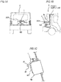
FIG 1A is a rear view (a foreign matter removal device is shown in a perspective view) of a vehicle,FIG 1B is a side view (the foreign matter removal device is shown in a perspective view) of a rear part of the vehicle, andFIG 1C is a partial enlarged view of the rear part of the vehicle. -
FIGS. 2A and 2B are views showing another example of a position where the foreign matter removal device is attached. -
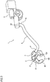
FIG 3 is a perspective view of a foreign matter removal device according to an embodiment of the present invention. -
FIG 4 is a configuration view of a high-pressure air generation unit included in the foreign matter removal device. -
FIGS. 5A to 5C are image views of a flow rate-time curve of high-pressure air generated by the high-pressure air generation unit and exhausted toward a nozzle. -
FIGS. 6A and 6B are schematic configuration views showing a positional relationship between the nozzle included in the foreign matter removal device and a lens of an in-vehicle camera. -
FIG 7 is a flow rate-time graph according to Example 1 of high-pressure air exhausted from the high-pressure air generation unit. -
FIG 8 is a flow rate-pressure-time graph according to Example 1. -
FIG 9 is a flow rate-time graph according to Example 2 of high-pressure air exhausted from the high-pressure air generation unit. -
FIG 10 is a flow rate-pressure-time graph of air exhausted from a pump according to a reference example. -
FIG 11 is a partial sectional view as seen from the side of the foreign matter removal device. -
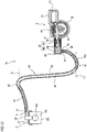
FIG 12 is a partial sectional view as seen from the side of the foreign matter removal device shown inFIGS. 2A and 2B . - Hereinafter, an example of an embodiment of the present invention will be described in detail with reference to the drawings.
- A foreign matter removal device of the present invention is applied as a device for removing foreign matters such as water droplets, mud and dust adhering to a lens of an in-vehicle camera, for example.
- As shown in
FIGS. 1A and 1B , a foreignmatter removal device 1 is attached to aback door 200A of a vehicle V, for example. The foreignmatter removal device 1 is provided with adrive unit 55, and a power supply terminal of thedrive unit 55 is connected to a power supply line of a vehicle. For example, with the triggering that a gear of the vehicle V has entered the reverse, a vehicle control unit (ECU; not shown) causes an in-vehicle camera 100 (to be described later) to start photographing, and the foreignmatter removal device 1 is controlled to operate by the vehicle control unit (ECU) within several seconds at the start of photographing, for example. - The in-
vehicle camera 100 is a camera for confirming, for example, the rear side of the vehicle V and, as shown inFIG. 1C , alens 101 of the in-vehicle camera 100 is attached to theback door 200A so that it is exposed toward the outside of theback door 200A of the vehicle V The in-vehicle camera 100 is provided with an imaging unit (not shown), and thelens 101 covers the imaging unit. As thelens 101, a simple translucent cover that does not converge or diffuse light is also included in the lens of this example. - Meanwhile, as shown in
FIGS. 2A and 2B , a foreignmatter removal device 1A may be attached to arear bumper 200B of the vehicle V, for example. Meanwhile, the position at which the in-vehicle camera 100 is attached is not limited to the rear end side of the vehicle but may be a body panel such as the front side or lateral side of the vehicle. Further, the in-vehicle camera 100 may be attached to a vehicle body via a vehicle mounted component such as a lamp, a door knob, a mirror, a bumper attached to the body panel, or the in-vehicle camera 100 may be mounted as a part (as an integral body) of these components. - As shown in
FIG 3 , the foreignmatter removal device 1 includes anozzle unit 2, ajoint member 3, ahose 4, and a high-pressureair generation unit 5. - The
nozzle unit 2 is configured to be removably attached to the in-vehicle camera 100. Thenozzle unit 2 includes anattachment part 21 and anozzle 22. Thenozzle unit 2 is formed of resin material, for example. - The
attachment part 21 is attached to ahousing 102 of the in-vehicle camera 100 so as to cover a top surface of the in-vehicle camera 100. Thenozzle 22 injects high-pressure air toward alens 101 of the in-vehicle camera 100. Thenozzle 22 is formed integrally with theattachment part 21. Thenozzle 22 is provided in such a way that an ejection port of thenozzle 22 faces thelens 101 when theattachment part 21 is attached to thehousing 102. Here, the phrase, "formed integrally with," means that an operator can handle thenozzle 22 and theattachment part 21 as an integral part during assembly work. Specifically, for example, thenozzle 22 and theattachment part 21 may be molded of the same material and in the same mold. Alternatively, thenozzle 22 and theattachment part 21 may be respectively molded of separate materials, and then, fitted together and formed integrally, thereby constituting thenozzle unit 2. - The
joint member 3 is a member for joining thenozzle 22 of thenozzle unit 2 and thehose 4. One end portion of thejoint member 3 is connected to thenozzle 22 and the opposite end portion thereof is connected to thehose 4. Thejoint member 3 is formed of resin material, for example. - The
hose 4 is a piping member that connects, together with thejoint member 3, thenozzle 22 and a high-pressureair generation unit 5. One end portion of thehose 4 is connected to thejoint member 3 and the opposite end portion thereof is connected to adischarge port 50 of the high-pressureair generation unit 5. Thehose 4 is formed of, for example, a material such as resin or rubber. - The high-pressure
air generation unit 5 is a unit for generating high-pressure air to be fed to thenozzle 22, and is, for example, a single-cylinder type reciprocating pump. The high-pressureair generation unit 5 is attached to a part of a vehicle body at the inside of a vehicle. - As shown in
FIG 4 , the high-pressureair generation unit 5 includes acase body 51 and a moving mechanism disposed inside thecase body 51. Of a moving direction of apiston 52 in the high-pressureair generation unit 5, a rearward direction that is a direction of feeding out air refers to a feeding direction, and a forward direction that is opposite to the feeding direction refers to a force accumulation direction. - The high-pressure
air generation unit 5 includes apiston 52 for feeding out high-pressure air, an urgingspring 58 for urging thepiston 52 in a feeding direction of the high-pressure air, and a rack-and-pinion gear mechanism for allowing thepiston 52 to slide according to the feeding direction of the high-pressure air. In an initial state before high-pressure air is fed out, thepiston 52 is positioned on the feeding direction side by an urging force of the urgingspring 58, and arack 53 is positioned in a state where arack portion 53a is engageable with agear portion 54a of apinion 54. - When the driving of the motor (drive unit) 55 is started and a driving force of the
motor 55 is transmitted to aworm wheel 57 via aworm 56, thegear portion 54a of thepinion 54 is meshed with therack portion 53a of therack 53. Therefore, therack 53 moves in the force accumulation direction against an urging force of an urgingspring 58 in accordance with the rotation of thepinion 54. As therack 53 moves in the force accumulation direction, the meshing between thegear portion 54a and therack portion 53a is released at a predetermined position. The position (position shown inFIG 4 ) where the meshing between thegear portion 54a and therack portion 53a is released is set as the bottom dead center of thepiston 52. In a state in which thepiston 52 is positioned at the bottom dead center, the air (outside air) flowing into a substantially front half portion (second space) 60b of aninternal space 60 of apiston support portion 59 passes through agap 61b along astep 61a and flows toward a substantially rear half portion (first space) 60a of theinternal space 60. - When the
piston 52 is moved to the bottom dead center, the meshing between thegear portion 54a and therack portion 53a is released, and thepiston 52 is moved in the feeding direction at a speed higher than the moving speed in the force accumulation direction by an urging force of the urgingspring 58. Meanwhile, the position where anend portion 52A of thepiston 52 is moved to an imaginary line L of thefirst space 60a is defined as the top dead center. In this way, the air flowing from thesecond space 60b to thefirst space 60a passes through thedischarge port 50 of aconnection protrusion 62 from thefirst space 60a and is fed toward thenozzle 22 of thenozzle unit 2 via thehose 4. At this time, since the diameter of thedischarge port 50 is smaller than that of thepiston support portion 59, the air discharged from thefirst space 60a through thedischarge port 50 is compressed into high-pressure air and is fed out. - In the present embodiment, a volume Vo of the
internal space 60 of thepiston support portion 59 of the high-pressureair generation unit 5 is 10cm3 or less. The volume Vo is a volume of thefirst space 60a in a state in which thepiston 52 is positioned at the bottom dead center (seeFIG 4 ). -
FIGS. 5A to 5C are image views of a flow rate-time curve of high-pressure air generated by the high-pressureair generation unit 5 and exhausted from a tip end of thenozzle 22 toward thelens 101 of the in-vehicle camera 100. - As shown in
FIG 5A , the high-pressure air generated by the high-pressureair generation unit 5 flows into thenozzle 22 and is exhausted from a tip end of thenozzle 22 toward thelens 101 of the in-vehicle camera 100. At this time, the maximum flow rate is represented as Q1 (cm3/s), and the time required for every exhaust is represented as t1(s). As a result of intensive study by the inventors, it has been found that the exhaust time t1(s) per cycle of the air in thefirst space 60a is desirably set to 0.03 seconds or less in order to remove water droplets adhering on thelens 101 of the in-vehicle camera 100 by using the small high-pressure air generation unit 5 (single-cylinder type reciprocating pump) in which the volume Vo of theinternal space 60 of thepiston support portion 59 is 10cm3 or less. When the exhaust time t1(s) per cycle is longer than 0.03 seconds, it is difficult to sufficiently secure the flow velocity or maximum flow rate Q1 of the high-pressure air, and therefore, it is difficult to properly blow away water droplets adhering on thelens 101. Further, the maximum flow rate Q1 in the exhaust per cycle is preferably 100cm3/s or more, more preferably 150cm3/s or more. By setting the maximum flow rate Q1 to 100cm3/s or more, it is possible to reliably remove water droplets or the like on thelens 101. Meanwhile, inFIG 5A , the amount of air exhausted at the maximum flow rate Q1 within the exhaust time t1 per cycle corresponds to the volume Vo of thefirst space 60a of thepiston support portion 59. - Further, as shown in
FIG 5B , during a predetermined time t2(s) of the exhaust time t1(s) per cycle, it is preferable that high-pressure air is discarded so as to maintain a predetermined flow rate Q2 (cm3/s). Specifically, during at least 0.02 seconds (time t2) of the exhaust time t1 per cycle, it is preferable to exhaust the high-pressure air so that the flow rate Q2 of the high-pressure air becomes 50cm3/s or more. The reason is that, in order to remove water droplets, it is preferable to perform the exhaust for a certain time in a region where the flow rate of the high-pressureair generation unit 5 is somewhat high. - The high-pressure
air generation unit 5 is controlled so as to repeatedly exhaust the high-pressure air. Preferably, the exhausting of the high-pressure air from the high-pressureair generation unit 5 is performed at least once per one second. For example, as shown inFIG 5C , the exhaust interval t3(s) of the high-pressure air is set as the time between the timings when the maximum flow rate of each exhaust time t1 is reached. By evacuating the high-pressure air generation unit 5 a plurality of times in a short cycle, it is possible to quickly remove water droplets newly adhering to the surface of thelens 101 after removing water droplets. - In
FIG 5C , the time during which thepiston 52 in the high-pressureair generation unit 5 moves from the top dead center (a state in which theend portion 52A is located at the imaginary line L of thefirst space 60a) to the bottom dead center (a state shown inFIG. 4 ) is defined as a force accumulation time t4(s), and the time during which thepiston 52 moves from the bottom dead center to the top dead center is defined as an exhaust time (feeding time) t1. At this time, as shown inFIG 5C , it is preferable that the force accumulation time t4 is ten times or more the feeding time t1. In this way, by slowly moving thepiston 52 from the top dead center to the bottom dead center while instantaneously moving thepiston 52 from the bottom dead center to the top dead center, that is, by instantaneously exhausting the air within the feeding time t1 while securing the force accumulation time t4 which is sufficiently longer than the feeding time t1, it is possible to reliably move water droplets adhering to thelens 101 even in the high-pressureair generation unit 5 where an urging force of the urgingspring 58 is small. - As described above, the
nozzle unit 2 is configured to be removably attached to the in-vehicle camera 100. However, as shown inFIG 6A , when an angle formed by a line C passing through the center of the ejectingport 24 of thenozzle 22 and a tangential line of the apex of thelens 101 is defined as θ, thenozzle 22 is positioned with respect to thelens 101 so that the angle θ is 0° or more but 60° or less. Preferably, the angle θ is 5° or more but 30° or less. In this way, by arranging the ejectingport 24 of thenozzle 22 with respect to thelens 101 while maintaining a predetermined slope, the high-pressure air can be easily blown onto the entire surface of thelens 101, thereby enhancing the performance of removing water droplets. Meanwhile, in the case where the lens mounted on the in-vehicle camera is a planar lens (e.g., plano-concave lens) instead of thecurved lens 101 as in the present embodiment, a line along the surface of the planar lens is considered as the above tangential line, and thenozzle 22 may be positioned with respect to the planar lens so that the angle θ formed by the surface of the lens and the center line C of the ejectingport 24 of thenozzle 22 is 0° or more but 60° or less. - Further, as shown in
FIG 6B , when thelens 101 is divided into six equal parts in the upper and lower direction, and afirst region 101A, asecond region 101B, athird region 101C, afourth region 101D, afifth region 101E and asixth region 101F from the upper are defined, the center line C of the ejectingport 24 of thenozzle 22 intersects with thesecond region 101B which is the second portion from the top of thelens 101. In this way, by positioning the ejectingport 24 of thenozzle 22 toward a certain region (second region 101B) on the upper side of thelens 101, the high-pressure air can be easily blown onto the entire surface of thelens 101, thereby enhancing the performance of removing water droplets. - Next, an operation of the foreign
matter removal device 1 will be described with reference toFIGS. 3 and4 again. - When the driving of the
motor 55 in the high-pressureair generation unit 5 is started, first, air (outside air) for generating high-pressure air is sucked. The air is sucked into the high-pressureair generation unit 5 from the ejectingport 24 of thenozzle 22. The sucked air is fed out, as high-pressure air, from thedischarge port 50 of the high-pressureair generation unit 5 to thehose 4 by piston motion due to an urging force of the urgingspring 58. The high-pressure air is fed from thehose 4 to thenozzle 22 of thenozzle unit 2 through thejoint member 3. - The high-pressure air flows into the
nozzle 22, is injected from the ejectingport 24 of thenozzle 22 and is blown toward thelens 101 of the in-vehicle camera 100 at a predetermined angle. The high-pressure air ejected from the ejectingport 24 is blown toward thelens 101 of the in-vehicle camera 100. In this way, foreign matters adhering to thelens 101 are blown away, so that the dirt of thelens 101 is eliminated. -
FIG 7 is a flow rate-time graph according to Example 1 of high-pressure air exhausted from the high-pressure air generation unit, andFIG 8 is a flow rate-pressure-time graph according to Example 1. In Example 1, the high-pressure air generation unit having a volume Vo of 10cm3 or less is used, and the nozzle having a tip end opening with a diameter of ϕ 1.2mm is used. - As shown in
FIGS. 7 and 8 , in Example 1, the exhaust time per cycle is about 10ms (0.01s), the maximum flow rate is about 275cm3/s, and the exhaust interval is 550ms. Further, the maximum pressure during the exhaust is about 80kPa. - It was confirmed that water adhering on the lens can be appropriately removed by evacuating the nozzle at the flow rate, the exhaust time, and the exhaust interval shown in the flow rate-time graph of Example 1.
-
FIG 9 is a flow rate-time graph according to Example 2 of high-pressure air exhausted from the high-pressure air generation unit. Also in Example 2, similar to Example 1, the high-pressure air generation unit having a volume Vo of 10cm3 or less is used, and the nozzle having a tip end opening with a diameter of ϕ 1.2mm is used. - As shown in
FIG 9 , in Example 2, the exhaust time per cycle is about 10ms (0.01s) similar to Example 1, but the maximum flow rate is about 200cm3/s and the exhaust interval is 280ms. - It was confirmed that water adhering on the lens can be appropriately removed by evacuating the nozzle at the flow rate, the exhaust time, and the exhaust interval shown in the flow rate-time graph of Example 2. Further, it can be confirmed that, by making the exhaust interval of Example 2 shorter than Example 1, i.e., performing the exhaust more frequently, the performance of removing foreign matters can be maintained even when the maximum flow rate per cycle is suppressed lower than in Example 1.
- Meanwhile, the necessary flow rate Q at the exhaust time t1 per cycle is obtained as follows.
- For example, in an in-vehicle camera having a lens with a predetermined outer diameter (e.g., 15mm), assuming that the total amount of water droplets adhering to the surface of the lens is 3cm3, the kinetic energy F for moving water of 3cm3 on the lens by 15mm is obtained by the following equation (1).
- [Equation 1]

- On the other hand, the energy W of air (wind) injected from the nozzle toward the lens is obtained by the following equation (2).
- [Equation 2]

- From the kinetic energy F obtained by the equation (1) and the energy W of the air (wind) obtained by the equation (2), a wind velocity V for moving water of 3cm3 on the lens by 15mm is obtained by the following equation (3). Meanwhile, at this time, the unit time t is 0.01s.
- [Equation 3]

- Based on the wind velocity W obtained by the equation (3), the flow rate Q required for the high-pressure air generation unit is obtained by the following equation (4).
- [Equation 4]

- In this way, by appropriately setting the surface area of the lens, the total amount of water droplets adhering to the lens, the opening area of the nozzle, and the unit time or the like, the flow rate Q required for the high-pressure
air generation unit 5 in order to appropriately remove water droplets or the like adhering to the surface of the lens can be obtained. In the present embodiment, as a result of intensive study by the inventors based on the necessary flow rate Q of the high-pressureair generation unit 5, a preferable range of the exhaust time t1, the exhaust interval t3 and the minimum required flow rate Q2 or the like has been found in order to achieve the compatibility between the size reduction of the high-pressureair generation unit 5 and the foreign matter removal performance. -
FIG 10 is a flow rate-pressure-time graph of high-pressure air exhausted from a high-pressure air generation unit according to a reference example. In the reference example, similar to Example 1, the nozzle having a tip end opening with a diameter of ϕ 1.2mm is used. - In the reference example, the exhaust time per cycle is about 200ms (0.2s), the maximum flow rate is about 125cm3/s, and the pressure during the exhaust is about 50kPa. As shown in the reference example, conventionally, the exhaust time per cycle is lengthened in order to remove water adhering on the lens, and the exhaust is performed at a relatively small flow rate. In this case, it is necessary to increase the volume of the high-pressure air generation unit (e.g., single-cylinder type reciprocating pump), and space saving cannot be achieved.
- On the contrary, according to the foreign
matter removal device 1 of the present embodiment, the high-pressureair generation unit 5 in which the volume Vo of the internal space (first space) 60a is 10cm3 or less is used, and the high-pressure air is injected so that the exhaust time t1 per cycle required for exhausting the air in theinternal space 60a is 0.03s or less. In this way, in the present embodiment, the air in the high-pressureair generation unit 5 having a small volume of 10cm3 or less is adapted to be instantaneously exhausted, and water droplets on the surface of thelens 101 can be appropriately moved without causing an increase in the volume Vo of the high-pressureair generation unit 5, so that it is possible to achieve the compatibility between the maintaining of the foreign matter removal performance and the size reduction of the device. - Further, according to the present embodiment, the exhaust form the high-pressure air generation unit is set so that the air flow rate Q2 is maintained at 50cm3/s or more during 0.02s of the exhaust time t1. In this way, since the high-pressure
air generation unit 5 is driven so as to maintain a high flow rate region for a certain period of time, water droplets can be more reliably removed. - Further, according to the present embodiment, the exhaust from the high-pressure
air generation unit 5 is performed a plurality of times in a short cycle of at least one per second. Therefore, for example, it is possible to quickly remove water droplets newly adhering to the surface of thelens 101 after removing water droplets without giving any discomfort to a driver. - Further, the foreign matter removal device of the present embodiment is configured such that the angle θ formed by the line C passing through the center of the ejecting
port 24 of thenozzle 22 and the tangential line of the apex of thelens 101 is 0° or more but 60° or less, and, the center line C of the ejectingport 24 of thenozzle 22 intersects with thesecond region 101B which is the second portion from the top of thelens 101 when thelens 101 is divided into six equal parts in the upper and lower direction. Furthermore, the time (force accumulation time) t4 when thepiston 52 in the high-pressureair generation unit 5 is at the bottom dead center is ten times or more the time (exhaust time) t1 when thepiston 52 is at the top dead center. With these configurations, it is possible to more reliably remove water droplets on thelens 101 even when the high-pressureair generation unit 5 having a small volume and a small power is used. -
FIG 11 is a partial sectional view as seen from the side of the foreignmatter removal device 1. - As shown in
FIG 11 , in the foreignmatter removal device 1, the high-pressureair generation unit 5 and the in-vehicle camera 100 to which thenozzle unit 2 is attached are arranged such that the high-pressureair generation unit 5 is located above thenozzle unit 2 in the upper and lower direction of the vehicle body. Then, the shape of thepiston support portion 59 and the diameter and length of thehose 4 are set such that a volume Vh of aninternal space 43 of thehose 4 is larger than the volume Vo of thefirst space 60a of thepiston support portion 59. Meanwhile, the volume Vo corresponds to the volume of thefirst space 60a in a state (seeFIGS. 3 and4 ) in which thepiston 52 is located at the bottom dead center. In this way, thehose 4 connecting the high-pressureair generation unit 5 and the nozzle unit 2 (joint member 3) has a function of preventing the reverse flow of water. - By the way, when the driving of the drive motor in the high-pressure
air generation unit 5 is started and air (outside air) for generating high-pressure air is sucked from the tip end of thenozzle 22, water or mud or the like may be introduced from the tip end of thenozzle 22, and these foreign matters may enter the high-pressureair generation unit 5. Therefore, conventionally, in addition to the hose (exhaust pipeline) connecting the nozzle and the high-pressure air generation unit that is an air pump, an intake pipeline is provided in the high-pressure air generation unit and a one way valve (check valve) is provided in each of the exhaust pipeline and the intake pipeline, thereby preventing water or the like from entering the high-pressureair generation unit 5. - On the contrary, in the present embodiment, the volume Vh of the
internal space 43 of thehose 4 is larger than the volume Vo of thefirst space 60a of thepiston support portion 59. Therefore, even when foreign matters such as water are introduced from the tip end of thenozzle 22 at the time of generating high-pressure air by the high-pressureair generation unit 5, it is possible to prevent foreign matters from entering into thepiston support portion 59 of the high-pressureair generation unit 5. As a result, the desired high-pressure air can be generated without causing the failure or breakage of the high-pressureair generation unit 5, and can be injected from thenozzle 22 toward thelens 101. Further, since the high-pressureair generation unit 5 is located above thenozzle unit 2 in the upper and lower direction of the vehicle body, it is possible to more reliably prevent the reverse flow of water or the like, and it is possible to maintain the performance of removing foreign matters adhering to thelens 101 of the in-vehicle camera 100. Furthermore, an intake pipeline for intake is provided in the high-pressureair generation unit 5 and a water reverse flow prevention mechanism can be provided without mounting a new component such as a check valve on thehose 4 or the intake pipeline, for example. In this way, the configuration of the foreignmatter removal device 1 is very simple. - Next, modified examples of the foreign
matter removal device 1 will be described with reference toFIGS. 2 and12 . - As described above, as shown in
FIGS. 2A and 2B , the foreignmatter removal device 1A may be attached to therear bumper 200B of the vehicle V, for example. At this time, due to the structure of the vehicle, it may be necessary to arrange the high-pressureair generation unit 5 so as to be located on the lower side of the vehicle body than the in-vehicle camera 100 to which thenozzle unit 2 is attached. - As shown in
FIG 12 , ahose 4A of the foreignmatter removal device 1A has anintermediate portion 44 which is located below arear end portion 41 connected to thejoint member 3 and afront end portion 42 connected to the high-pressureair generation unit 5 in the upper and lower direction of the vehicle. Further, from therear end portion 41 connected to thejoint member 3, thehose 4A is temporarily disposed on the upper side. And then, thehose 4A is bent in a substantially U shape, and thefront end portion 42 is connected to the high-pressureair generation unit 5. That is, thehose 4A is composed of amountain portion 45 and avalley portion 46. - In this way, when the high-pressure
air generation unit 5 is arranged at a position lower than thenozzle 22, thehose 4A secures a volume of theinternal space 43 larger than the volume Vo of thefirst space 60a of thepiston support portion 59 at a position higher than thenozzle 22. That is, in the foreignmatter removal device 1A, a volume Vh1 of theinternal space 43 from therear end portion 41 of thehose 4A to an inflection point L1 where thehose 4A is inflected downward is set to be larger than the volume Vo of thefirst space 60a of thepiston support portion 59. Therefore, even when the air in thehose 4A is sucked into thepiston support portion 59 at the time of generating high-pressure air by the high-pressureair generation unit 5, it is possible to prevent the water flowing backward from the tip end of thenozzle 22 from flowing toward the high-pressureair generation unit 5 beyond themountain portion 45 of thehose 4A. In this way, it is possible to maintain the performance of the foreignmatter removal device 1A. - Further, preferably, the foreign
matter removal device 1A is configured such that a volume Vh2 of theinternal space 43 from an inflection point L2 where thehose 4A is inflected upward at theintermediate portion 44 of thehose 4A to thefront end portion 42 connected to the high-pressureair generation unit 5 is larger than the volume Vo of thefirst space 60a of thepiston support portion 59. According to this configuration, for example, even when water enters thevalley portion 46 of thehose 4A from thenozzle 22, the water does not flow backward to the inside of the high-pressureair generation unit 5, and thus, it is possible to maintain the performance of the foreignmatter removal device 1A. - Although the embodiments of the present invention have been illustratively described above, the present invention is not limited to these embodiments, and other configurations can be adopted as necessary.
- In the above embodiments, the
joint member 3 is provided as a member for joining thenozzle 22 of thenozzle unit 2 and thehose 4. However, in the case where there is no need to change the posture of thehose 4 with respect to thenozzle 22, thehose 4 may be directly attached to thenozzle 22 without providing thejoint member 3. - Further, in the above-described examples, the application to the camera (not limited to visible light) has been described. However, the sensor to which the present invention is applied is not limited to this. The present invention may be applied to sensors attachable to vehicles, such as LIDAE (laser radar), millimeter wave radars, and ultrasonic sensors.
- Further, the target portion from which the foreign matter removal device removes foreign matters is not limited to the lens of the camera. For example, the present invention can be applied to a foreign matter removal device for removing foreign matters adhering on "partition wall" which is defined as a concept including an optical lens of a sensor element, a cover for covering a front surface of an optical lens, a cover for covering a vehicle mounted component such as a lamp having a part serving as a communication window of a sensor, a mirror, a bumper, a grill and a door knob, and a vehicle window when a sensor is mounted in a vehicle compartment. Meanwhile, this partition wall is not limited to a transparent member (translucency), but may not be transparent in an ultrasonic sensor, a millimeter wave radar or the like.
- For example, in the above embodiments, the application of the foreign matter removal device to the in-vehicle camera has been described. However, the object to which the present invention is applied is not limited as long as it is a camera used outdoors. For example, a camera mounted so as to be exposed to the outside of an airplane, a railroad, a ship, a robot, an outdoor installation object, a building and the like may be included.
- The present application is based on
Japanese Patent Application (Patent Application No. 2015-131789) filed on June 30, 2015 Japanese Patent Application (Patent Application No. 2015-131790) filed on June 30, 2015
Claims (5)
- A vehicle (V) comprising a foreign matter removal device (1, 1A) configured to remove foreign matter on a lens (101) of a camera (100), the foreign matter removal device (1, 1A) comprising:a generation unit (5) configured to generate high-pressure air;a nozzle (22) configured to inject the high-pressure air toward the in-vehicle camera (100); anda piping (4) connecting the generation unit (5) and the nozzle (22),wherein the piping (4) has a function of preventing reverse flow of water, andwherein a volume (Vh, Vh2) of an internal space (60) of the piping is larger than a volume (Vo) of an internal space (60) of the generation unit (5),characterized in thatan intermediate portion (44) of the piping (4) is located below one end portion (42) of the piping (4) connected to the generation unit (5) and the other end portion (41) of the piping (4) connected to the nozzle (22) in the upper and lower direction of the vehicle (V).
- The vehicle (V) according to claim 1, whereinthe generation unit (5) is configured of a pump using a piston (52), andthe volume (Vh, Vh2) of the internal space of the piping (4) is larger than a volume of an internal space of the pump.
- The vehicle (V) according to claims 1 or 2, wherein the generation unit (5) is arranged above the nozzle (22) in upper and lower direction of the vehicle (V).
- The vehicle according to claim 1, wherein the camera is an in-vehicle camera (100) attached to the vehicle (V) so that the lens (101) of the in-vehicle camera (100) is exposed toward an outside of a body panel of the vehicle.
- A vehicle (V) comprising a foreign matter removal device (1, 1A) configured to remove foreign matters adhering to a partition wall interposed between an in-vehicle sensor and a measuring target of the in-vehicle sensor, the foreign matter removal device (1, 1A) comprising:a generation unit (5) configured to generate high-pressure air;a nozzle (22) configured to inject the high-pressure air toward the partition wall; anda piping(4) connecting the generation unit (5) and the nozzle (22),wherein the piping (4) has a function of preventing reverse flow of water, andwherein a volume (Vh, Vh2) of an internal space (60) of the piping is larger than a volume (Vo) of an internal space (60) of the generation unit (5),characterized in thatan intermediate portion (44) of the piping (4) is located below one end portion (42) of the piping (4) connected to the generation unit (5) and the other end portion (41) of the piping (4) connected to the nozzle (22) in the upper and lower direction of the vehicle (V).
Applications Claiming Priority (4)
| Application Number | Priority Date | Filing Date | Title |
|---|---|---|---|
| JP2015131789 | 2015-06-30 | ||
| JP2015131790 | 2015-06-30 | ||
| EP16817987.7A EP3318455B1 (en) | 2015-06-30 | 2016-06-29 | Foreign material removing device and vehicle provided with this foreign material removing device |
| PCT/JP2016/069336 WO2017002879A1 (en) | 2015-06-30 | 2016-06-29 | Foreign material removing device and vehicle provided with this foreign material removing device |
Related Parent Applications (2)
| Application Number | Title | Priority Date | Filing Date |
|---|---|---|---|
| EP16817987.7A Division EP3318455B1 (en) | 2015-06-30 | 2016-06-29 | Foreign material removing device and vehicle provided with this foreign material removing device |
| EP16817987.7A Division-Into EP3318455B1 (en) | 2015-06-30 | 2016-06-29 | Foreign material removing device and vehicle provided with this foreign material removing device |
Publications (2)
| Publication Number | Publication Date |
|---|---|
| EP3581445A1 EP3581445A1 (en) | 2019-12-18 |
| EP3581445B1 true EP3581445B1 (en) | 2021-11-03 |
Family
ID=57608578
Family Applications (2)
| Application Number | Title | Priority Date | Filing Date |
|---|---|---|---|
| EP19189402.1A Active EP3581445B1 (en) | 2015-06-30 | 2016-06-29 | Foreign material removing device and vehicle provided with this foreign material removing device |
| EP16817987.7A Active EP3318455B1 (en) | 2015-06-30 | 2016-06-29 | Foreign material removing device and vehicle provided with this foreign material removing device |
Family Applications After (1)
| Application Number | Title | Priority Date | Filing Date |
|---|---|---|---|
| EP16817987.7A Active EP3318455B1 (en) | 2015-06-30 | 2016-06-29 | Foreign material removing device and vehicle provided with this foreign material removing device |
Country Status (5)
| Country | Link |
|---|---|
| US (2) | US11155244B2 (en) |
| EP (2) | EP3581445B1 (en) |
| JP (1) | JP6846346B2 (en) |
| CN (2) | CN111497788B (en) |
| WO (1) | WO2017002879A1 (en) |
Families Citing this family (19)
| Publication number | Priority date | Publication date | Assignee | Title |
|---|---|---|---|---|
| US10350647B2 (en) | 2011-03-10 | 2019-07-16 | Dlhbowles, Inc. | Integrated automotive system, nozzle assembly and remote control method for cleaning an image sensor's exterior or objective lens surface |
| WO2012138455A1 (en) | 2011-03-10 | 2012-10-11 | Bowles Fluidics Corporation | Integrated automotive system, nozzle assembly and remote control method for cleaning an image sensor's lens |
| JP2017513772A (en) | 2014-04-11 | 2017-06-01 | ディエルエイチ・ボウルズ・インコーポレイテッドdlhBOWLES Inc. | Compact thin nozzle assembly and compact fluid circuit as an integrated automotive system for wide-angle image sensor exterior cleaning |
| WO2015161097A1 (en) | 2014-04-16 | 2015-10-22 | Bowles Fludics Corporation | Integrated multi image sensor and lens washing nozzle assembly and method for simultaneously cleaning multiple image sensors |
| JP6764385B2 (en) * | 2017-01-20 | 2020-09-30 | 株式会社ニフコ | Fluid spraying device for vehicle cameras |
| JP6948696B2 (en) * | 2017-06-29 | 2021-10-13 | フジクス株式会社 | Camera device with dirt removal function |
| US11403865B2 (en) * | 2017-07-25 | 2022-08-02 | Nec Corporation | Number-of-occupants detection system, number-of-occupants detection method, and program |
| CN107765113B (en) * | 2017-09-12 | 2021-01-05 | 江西洪都航空工业集团有限责任公司 | Method for shunting aircraft test signal |
| US20190106085A1 (en) * | 2017-10-10 | 2019-04-11 | GM Global Technology Operations LLC | System and method for automated decontamination of vehicle optical sensor lens covers |
| US10549723B2 (en) * | 2018-05-04 | 2020-02-04 | Ford Global Technologies, Llc | Vehicle object-detection sensor assembly |
| FR3089185B1 (en) * | 2018-11-29 | 2022-06-10 | Thales Sa | DIRT EVACUATION DEVICE ON A LASER DOPPLER ANEMOMETRY SENSOR PORTHOLE FOR A ROTARY WING AIRCRAFT |
| US10802121B1 (en) * | 2019-10-09 | 2020-10-13 | Ford Global Technologies, Llc | Cleaning apparatus for sensor |
| CN111762017A (en) * | 2020-06-28 | 2020-10-13 | 阜阳常阳汽车部件有限公司 | Truck frame with integrated configuration |
| TWI750901B (en) * | 2020-11-18 | 2021-12-21 | 同致電子企業股份有限公司 | Superficial foreign bodies detecting system for ultrasonic sensor |
| US12019460B2 (en) | 2021-06-24 | 2024-06-25 | Apple Inc. | Shared compressor |
| US12285769B2 (en) | 2021-07-06 | 2025-04-29 | Abc Technologies Inc. | Pulsating spray cleaning nozzle assembly and method |
| US12099147B2 (en) * | 2022-05-12 | 2024-09-24 | GM Global Technology Operations LLC | Surface cleaning system to clean lidar sensor of an autonomous vehicle |
| KR20240087957A (en) | 2022-12-13 | 2024-06-20 | 현대자동차주식회사 | Cleaning device |
| KR20240140277A (en) | 2023-03-16 | 2024-09-24 | 현대자동차주식회사 | Sensor cleaning system |
Citations (1)
| Publication number | Priority date | Publication date | Assignee | Title |
|---|---|---|---|---|
| EP3239006A1 (en) * | 2014-12-22 | 2017-11-01 | Koito Manufacturing Co., Ltd. | Foreign body removal device and removal drive device |
Family Cites Families (29)
| Publication number | Priority date | Publication date | Assignee | Title |
|---|---|---|---|---|
| US1122544A (en) * | 1914-02-24 | 1914-12-29 | Disinfectant And Utilities Corp | Automatic spraying device. |
| BE501701A (en) * | 1950-04-15 | |||
| FR1472032A (en) * | 1965-03-12 | 1967-03-10 | Reciprocating drive machine with electromagnetic control | |
| JPS5950201A (en) * | 1982-09-14 | 1984-03-23 | Nissan Motor Co Ltd | Reserve tank device |
| JP3010863B2 (en) * | 1991-12-06 | 2000-02-21 | 松下電器産業株式会社 | Bath bubble generator |
| JPH09292656A (en) * | 1996-02-27 | 1997-11-11 | Fuji Photo Optical Co Ltd | Water drop remover for camera lens |
| KR19990024944U (en) * | 1997-12-16 | 1999-07-05 | 홍종만 | Water Droplet Removal Device for Door Glass |
| JPH11321585A (en) * | 1998-05-12 | 1999-11-24 | Honda Motor Co Ltd | Water droplet removal control device for vehicles |
| JP2001171491A (en) * | 1999-12-16 | 2001-06-26 | Matsushita Electric Ind Co Ltd | Vehicle-mounted camera device and method of cleaning vehicle-mounted camera |
| JP2002263154A (en) * | 2001-03-07 | 2002-09-17 | Sankyo:Kk | Bubble-generating body supporting device for bathtub |
| DE10149337A1 (en) * | 2001-10-06 | 2003-04-17 | Bosch Gmbh Robert | Device for a front cover unit of a motor vehicle removes solid or liquid material and/or prevents their adhesion to a given zone of the front cover unit |
| JP2004202145A (en) * | 2002-12-26 | 2004-07-22 | Yamanouchi Trading:Kk | Piston cylinder apparatus for air gun, and air gun |
| CN2776773Y (en) * | 2005-03-08 | 2006-05-03 | 程也坦 | Car rear mirror water removal device |
| JP2012201122A (en) * | 2011-03-23 | 2012-10-22 | Asmo Co Ltd | Nozzle device for vehicle-mounted camera, vehicle-mounted camera with cleaning device, and cleaning system for vehicle-mounted camera |
| JP5494743B2 (en) | 2011-10-14 | 2014-05-21 | 株式会社デンソー | Camera cleaning device |
| US20130146577A1 (en) * | 2011-12-08 | 2013-06-13 | Continental Automotive Systems, Inc. | Vehicle mounted optical and sensor cleaning system |
| JP2013154771A (en) * | 2012-01-30 | 2013-08-15 | Asmo Co Ltd | On-vehicle camera device |
| US9796359B2 (en) * | 2012-02-23 | 2017-10-24 | The Raymond Corporation | Method and apparatus for removing and preventing lens surface contamination on a vehicle lens |
| EP2873572B1 (en) * | 2012-07-11 | 2017-05-10 | Nissan Motor Co., Ltd. | Vehicle-mounted-camera cleaning device, and vehicle-mounted-camera cleaning method |
| MY154239A (en) * | 2012-07-27 | 2015-05-29 | Nissan Motor | Vehicle-mounted camera device |
| JP2014069586A (en) * | 2012-09-27 | 2014-04-21 | Asmo Co Ltd | Washer nozzle for on-vehicle camera |
| JP3182524U (en) * | 2013-01-17 | 2013-04-04 | 有限会社鹿屋ヂーゼル機器 | Vehicle disinfectant heating device |
| JP6213266B2 (en) | 2013-01-30 | 2017-10-18 | 住友化学株式会社 | Amide compounds and their use for controlling harmful arthropods |
| CN103362570B (en) * | 2013-05-04 | 2016-02-10 | 武汉宇宙源新型动力技术有限公司 | Air engine |
| JP6417757B2 (en) | 2013-09-19 | 2018-11-07 | 株式会社デンソー | In-vehicle optical sensor cleaning device |
| JP6338880B2 (en) | 2013-12-09 | 2018-06-06 | 株式会社ポーラファルマ | Pharmaceutical composition for external use |
| EP3132984B1 (en) | 2014-04-14 | 2019-11-20 | Koito Manufacturing Co., Ltd. | In vehicle device with foreign material removal |
| EP2949520B1 (en) | 2014-05-27 | 2018-03-21 | Fico Transpar, S.A. | System for cleaning a vehicle-mounted optic lens |
| US10059280B2 (en) * | 2014-06-06 | 2018-08-28 | Joseph Richard Cooper | Obstruction-removal system and method for vehicle-camera lens |
-
2016
- 2016-06-29 EP EP19189402.1A patent/EP3581445B1/en active Active
- 2016-06-29 CN CN202010241979.7A patent/CN111497788B/en active Active
- 2016-06-29 WO PCT/JP2016/069336 patent/WO2017002879A1/en not_active Ceased
- 2016-06-29 JP JP2017526413A patent/JP6846346B2/en active Active
- 2016-06-29 US US15/740,877 patent/US11155244B2/en active Active
- 2016-06-29 EP EP16817987.7A patent/EP3318455B1/en active Active
- 2016-06-29 CN CN201680038322.2A patent/CN107709107B/en active Active
-
2021
- 2021-08-05 US US17/394,559 patent/US11827188B2/en active Active
Patent Citations (1)
| Publication number | Priority date | Publication date | Assignee | Title |
|---|---|---|---|---|
| EP3239006A1 (en) * | 2014-12-22 | 2017-11-01 | Koito Manufacturing Co., Ltd. | Foreign body removal device and removal drive device |
Also Published As
| Publication number | Publication date |
|---|---|
| EP3318455A4 (en) | 2019-02-13 |
| CN111497788B (en) | 2023-09-29 |
| CN107709107A (en) | 2018-02-16 |
| US20180194330A1 (en) | 2018-07-12 |
| US11155244B2 (en) | 2021-10-26 |
| CN107709107B (en) | 2022-01-18 |
| JPWO2017002879A1 (en) | 2018-04-26 |
| CN111497788A (en) | 2020-08-07 |
| EP3318455A1 (en) | 2018-05-09 |
| EP3581445A1 (en) | 2019-12-18 |
| JP6846346B2 (en) | 2021-03-24 |
| EP3318455B1 (en) | 2021-04-07 |
| WO2017002879A1 (en) | 2017-01-05 |
| US20210362689A1 (en) | 2021-11-25 |
| US11827188B2 (en) | 2023-11-28 |
Similar Documents
| Publication | Publication Date | Title |
|---|---|---|
| US11827188B2 (en) | Foreign material removing device and vehicle provided with this foreign material removing device | |
| EP3318454B1 (en) | Foreign matter removal device and vehicle provided with same | |
| US11505163B2 (en) | Foreign matter removal device and vehicle equipped with foreign matter removal device | |
| JP7358595B2 (en) | Vehicle cleaner systems and vehicles equipped with vehicle cleaner systems | |
| EP3132984B1 (en) | In vehicle device with foreign material removal | |
| JP7555707B2 (en) | License plate lamp unit and vehicle equipped with the license plate lamp unit | |
| US12162442B2 (en) | Vehicular cleaner | |
| JP2012201122A (en) | Nozzle device for vehicle-mounted camera, vehicle-mounted camera with cleaning device, and cleaning system for vehicle-mounted camera | |
| CN108884976A (en) | Vehicle camera, vehicle lamp, and vehicle foreign matter removal system | |
| US20220126790A1 (en) | Vehicular cleaner and vehicular cleaner unit | |
| US12157440B2 (en) | Cleaner for vehicles, bracket for cleaners for vehicles, and cleaner unit for vehicles | |
| CN108238009B (en) | Washer and vehicle comprising a washer |
Legal Events
| Date | Code | Title | Description |
|---|---|---|---|
| PUAI | Public reference made under article 153(3) epc to a published international application that has entered the european phase |
Free format text: ORIGINAL CODE: 0009012 |
|
| STAA | Information on the status of an ep patent application or granted ep patent |
Free format text: STATUS: REQUEST FOR EXAMINATION WAS MADE |
|
| 17P | Request for examination filed |
Effective date: 20190731 |
|
| AC | Divisional application: reference to earlier application |
Ref document number: 3318455 Country of ref document: EP Kind code of ref document: P |
|
| AK | Designated contracting states |
Kind code of ref document: A1 Designated state(s): AL AT BE BG CH CY CZ DE DK EE ES FI FR GB GR HR HU IE IS IT LI LT LU LV MC MK MT NL NO PL PT RO RS SE SI SK SM TR |
|
| RBV | Designated contracting states (corrected) |
Designated state(s): AL AT BE BG CH CY CZ DE DK EE ES FI FR GB GR HR HU IE IS IT LI LT LU LV MC MK MT NL NO PL PT RO RS SE SI SK SM TR |
|
| STAA | Information on the status of an ep patent application or granted ep patent |
Free format text: STATUS: EXAMINATION IS IN PROGRESS |
|
| 17Q | First examination report despatched |
Effective date: 20200831 |
|
| GRAP | Despatch of communication of intention to grant a patent |
Free format text: ORIGINAL CODE: EPIDOSNIGR1 |
|
| STAA | Information on the status of an ep patent application or granted ep patent |
Free format text: STATUS: GRANT OF PATENT IS INTENDED |
|
| INTG | Intention to grant announced |
Effective date: 20210525 |
|
| GRAS | Grant fee paid |
Free format text: ORIGINAL CODE: EPIDOSNIGR3 |
|
| GRAA | (expected) grant |
Free format text: ORIGINAL CODE: 0009210 |
|
| STAA | Information on the status of an ep patent application or granted ep patent |
Free format text: STATUS: THE PATENT HAS BEEN GRANTED |
|
| AC | Divisional application: reference to earlier application |
Ref document number: 3318455 Country of ref document: EP Kind code of ref document: P |
|
| AK | Designated contracting states |
Kind code of ref document: B1 Designated state(s): AL AT BE BG CH CY CZ DE DK EE ES FI FR GB GR HR HU IE IS IT LI LT LU LV MC MK MT NL NO PL PT RO RS SE SI SK SM TR |
|
| REG | Reference to a national code |
Ref country code: GB Ref legal event code: FG4D |
|
| REG | Reference to a national code |
Ref country code: AT Ref legal event code: REF Ref document number: 1443697 Country of ref document: AT Kind code of ref document: T Effective date: 20211115 Ref country code: CH Ref legal event code: EP |
|
| REG | Reference to a national code |
Ref country code: IE Ref legal event code: FG4D |
|
| REG | Reference to a national code |
Ref country code: DE Ref legal event code: R096 Ref document number: 602016065902 Country of ref document: DE |
|
| REG | Reference to a national code |
Ref country code: LT Ref legal event code: MG9D |
|
| REG | Reference to a national code |
Ref country code: NL Ref legal event code: MP Effective date: 20211103 |
|
| REG | Reference to a national code |
Ref country code: AT Ref legal event code: MK05 Ref document number: 1443697 Country of ref document: AT Kind code of ref document: T Effective date: 20211103 |
|
| PG25 | Lapsed in a contracting state [announced via postgrant information from national office to epo] |
Ref country code: RS Free format text: LAPSE BECAUSE OF FAILURE TO SUBMIT A TRANSLATION OF THE DESCRIPTION OR TO PAY THE FEE WITHIN THE PRESCRIBED TIME-LIMIT Effective date: 20211103 Ref country code: LT Free format text: LAPSE BECAUSE OF FAILURE TO SUBMIT A TRANSLATION OF THE DESCRIPTION OR TO PAY THE FEE WITHIN THE PRESCRIBED TIME-LIMIT Effective date: 20211103 Ref country code: FI Free format text: LAPSE BECAUSE OF FAILURE TO SUBMIT A TRANSLATION OF THE DESCRIPTION OR TO PAY THE FEE WITHIN THE PRESCRIBED TIME-LIMIT Effective date: 20211103 Ref country code: BG Free format text: LAPSE BECAUSE OF FAILURE TO SUBMIT A TRANSLATION OF THE DESCRIPTION OR TO PAY THE FEE WITHIN THE PRESCRIBED TIME-LIMIT Effective date: 20220203 Ref country code: AT Free format text: LAPSE BECAUSE OF FAILURE TO SUBMIT A TRANSLATION OF THE DESCRIPTION OR TO PAY THE FEE WITHIN THE PRESCRIBED TIME-LIMIT Effective date: 20211103 |
|
| PG25 | Lapsed in a contracting state [announced via postgrant information from national office to epo] |
Ref country code: IS Free format text: LAPSE BECAUSE OF FAILURE TO SUBMIT A TRANSLATION OF THE DESCRIPTION OR TO PAY THE FEE WITHIN THE PRESCRIBED TIME-LIMIT Effective date: 20220303 Ref country code: SE Free format text: LAPSE BECAUSE OF FAILURE TO SUBMIT A TRANSLATION OF THE DESCRIPTION OR TO PAY THE FEE WITHIN THE PRESCRIBED TIME-LIMIT Effective date: 20211103 Ref country code: PT Free format text: LAPSE BECAUSE OF FAILURE TO SUBMIT A TRANSLATION OF THE DESCRIPTION OR TO PAY THE FEE WITHIN THE PRESCRIBED TIME-LIMIT Effective date: 20220303 Ref country code: PL Free format text: LAPSE BECAUSE OF FAILURE TO SUBMIT A TRANSLATION OF THE DESCRIPTION OR TO PAY THE FEE WITHIN THE PRESCRIBED TIME-LIMIT Effective date: 20211103 Ref country code: NO Free format text: LAPSE BECAUSE OF FAILURE TO SUBMIT A TRANSLATION OF THE DESCRIPTION OR TO PAY THE FEE WITHIN THE PRESCRIBED TIME-LIMIT Effective date: 20220203 Ref country code: NL Free format text: LAPSE BECAUSE OF FAILURE TO SUBMIT A TRANSLATION OF THE DESCRIPTION OR TO PAY THE FEE WITHIN THE PRESCRIBED TIME-LIMIT Effective date: 20211103 Ref country code: LV Free format text: LAPSE BECAUSE OF FAILURE TO SUBMIT A TRANSLATION OF THE DESCRIPTION OR TO PAY THE FEE WITHIN THE PRESCRIBED TIME-LIMIT Effective date: 20211103 Ref country code: HR Free format text: LAPSE BECAUSE OF FAILURE TO SUBMIT A TRANSLATION OF THE DESCRIPTION OR TO PAY THE FEE WITHIN THE PRESCRIBED TIME-LIMIT Effective date: 20211103 Ref country code: GR Free format text: LAPSE BECAUSE OF FAILURE TO SUBMIT A TRANSLATION OF THE DESCRIPTION OR TO PAY THE FEE WITHIN THE PRESCRIBED TIME-LIMIT Effective date: 20220204 Ref country code: ES Free format text: LAPSE BECAUSE OF FAILURE TO SUBMIT A TRANSLATION OF THE DESCRIPTION OR TO PAY THE FEE WITHIN THE PRESCRIBED TIME-LIMIT Effective date: 20211103 |
|
| PG25 | Lapsed in a contracting state [announced via postgrant information from national office to epo] |
Ref country code: SM Free format text: LAPSE BECAUSE OF FAILURE TO SUBMIT A TRANSLATION OF THE DESCRIPTION OR TO PAY THE FEE WITHIN THE PRESCRIBED TIME-LIMIT Effective date: 20211103 Ref country code: SK Free format text: LAPSE BECAUSE OF FAILURE TO SUBMIT A TRANSLATION OF THE DESCRIPTION OR TO PAY THE FEE WITHIN THE PRESCRIBED TIME-LIMIT Effective date: 20211103 Ref country code: RO Free format text: LAPSE BECAUSE OF FAILURE TO SUBMIT A TRANSLATION OF THE DESCRIPTION OR TO PAY THE FEE WITHIN THE PRESCRIBED TIME-LIMIT Effective date: 20211103 Ref country code: EE Free format text: LAPSE BECAUSE OF FAILURE TO SUBMIT A TRANSLATION OF THE DESCRIPTION OR TO PAY THE FEE WITHIN THE PRESCRIBED TIME-LIMIT Effective date: 20211103 Ref country code: DK Free format text: LAPSE BECAUSE OF FAILURE TO SUBMIT A TRANSLATION OF THE DESCRIPTION OR TO PAY THE FEE WITHIN THE PRESCRIBED TIME-LIMIT Effective date: 20211103 Ref country code: CZ Free format text: LAPSE BECAUSE OF FAILURE TO SUBMIT A TRANSLATION OF THE DESCRIPTION OR TO PAY THE FEE WITHIN THE PRESCRIBED TIME-LIMIT Effective date: 20211103 |
|
| REG | Reference to a national code |
Ref country code: DE Ref legal event code: R097 Ref document number: 602016065902 Country of ref document: DE |
|
| PLBE | No opposition filed within time limit |
Free format text: ORIGINAL CODE: 0009261 |
|
| STAA | Information on the status of an ep patent application or granted ep patent |
Free format text: STATUS: NO OPPOSITION FILED WITHIN TIME LIMIT |
|
| 26N | No opposition filed |
Effective date: 20220804 |
|
| PG25 | Lapsed in a contracting state [announced via postgrant information from national office to epo] |
Ref country code: AL Free format text: LAPSE BECAUSE OF FAILURE TO SUBMIT A TRANSLATION OF THE DESCRIPTION OR TO PAY THE FEE WITHIN THE PRESCRIBED TIME-LIMIT Effective date: 20211103 |
|
| PG25 | Lapsed in a contracting state [announced via postgrant information from national office to epo] |
Ref country code: SI Free format text: LAPSE BECAUSE OF FAILURE TO SUBMIT A TRANSLATION OF THE DESCRIPTION OR TO PAY THE FEE WITHIN THE PRESCRIBED TIME-LIMIT Effective date: 20211103 |
|
| PG25 | Lapsed in a contracting state [announced via postgrant information from national office to epo] |
Ref country code: MC Free format text: LAPSE BECAUSE OF FAILURE TO SUBMIT A TRANSLATION OF THE DESCRIPTION OR TO PAY THE FEE WITHIN THE PRESCRIBED TIME-LIMIT Effective date: 20211103 |
|
| REG | Reference to a national code |
Ref country code: CH Ref legal event code: PL |
|
| REG | Reference to a national code |
Ref country code: BE Ref legal event code: MM Effective date: 20220630 |
|
| GBPC | Gb: european patent ceased through non-payment of renewal fee |
Effective date: 20220629 |
|
| PG25 | Lapsed in a contracting state [announced via postgrant information from national office to epo] |
Ref country code: LU Free format text: LAPSE BECAUSE OF NON-PAYMENT OF DUE FEES Effective date: 20220629 Ref country code: LI Free format text: LAPSE BECAUSE OF NON-PAYMENT OF DUE FEES Effective date: 20220630 Ref country code: IE Free format text: LAPSE BECAUSE OF NON-PAYMENT OF DUE FEES Effective date: 20220629 Ref country code: CH Free format text: LAPSE BECAUSE OF NON-PAYMENT OF DUE FEES Effective date: 20220630 |
|
| PG25 | Lapsed in a contracting state [announced via postgrant information from national office to epo] |
Ref country code: IT Free format text: LAPSE BECAUSE OF FAILURE TO SUBMIT A TRANSLATION OF THE DESCRIPTION OR TO PAY THE FEE WITHIN THE PRESCRIBED TIME-LIMIT Effective date: 20211103 Ref country code: GB Free format text: LAPSE BECAUSE OF NON-PAYMENT OF DUE FEES Effective date: 20220629 Ref country code: BE Free format text: LAPSE BECAUSE OF NON-PAYMENT OF DUE FEES Effective date: 20220630 |
|
| P01 | Opt-out of the competence of the unified patent court (upc) registered |
Effective date: 20230509 |
|
| PG25 | Lapsed in a contracting state [announced via postgrant information from national office to epo] |
Ref country code: MK Free format text: LAPSE BECAUSE OF FAILURE TO SUBMIT A TRANSLATION OF THE DESCRIPTION OR TO PAY THE FEE WITHIN THE PRESCRIBED TIME-LIMIT Effective date: 20211103 Ref country code: CY Free format text: LAPSE BECAUSE OF FAILURE TO SUBMIT A TRANSLATION OF THE DESCRIPTION OR TO PAY THE FEE WITHIN THE PRESCRIBED TIME-LIMIT Effective date: 20211103 |
|
| PG25 | Lapsed in a contracting state [announced via postgrant information from national office to epo] |
Ref country code: HU Free format text: LAPSE BECAUSE OF FAILURE TO SUBMIT A TRANSLATION OF THE DESCRIPTION OR TO PAY THE FEE WITHIN THE PRESCRIBED TIME-LIMIT; INVALID AB INITIO Effective date: 20160629 |
|
| PG25 | Lapsed in a contracting state [announced via postgrant information from national office to epo] |
Ref country code: TR Free format text: LAPSE BECAUSE OF FAILURE TO SUBMIT A TRANSLATION OF THE DESCRIPTION OR TO PAY THE FEE WITHIN THE PRESCRIBED TIME-LIMIT Effective date: 20211103 |
|
| PG25 | Lapsed in a contracting state [announced via postgrant information from national office to epo] |
Ref country code: MT Free format text: LAPSE BECAUSE OF FAILURE TO SUBMIT A TRANSLATION OF THE DESCRIPTION OR TO PAY THE FEE WITHIN THE PRESCRIBED TIME-LIMIT Effective date: 20211103 |
|
| PGFP | Annual fee paid to national office [announced via postgrant information from national office to epo] |
Ref country code: DE Payment date: 20250507 Year of fee payment: 10 |
|
| PGFP | Annual fee paid to national office [announced via postgrant information from national office to epo] |
Ref country code: FR Payment date: 20250508 Year of fee payment: 10 |