JP6764385B2 - Fluid spraying device for vehicle cameras - Google Patents
Fluid spraying device for vehicle cameras Download PDFInfo
- Publication number
- JP6764385B2 JP6764385B2 JP2017182228A JP2017182228A JP6764385B2 JP 6764385 B2 JP6764385 B2 JP 6764385B2 JP 2017182228 A JP2017182228 A JP 2017182228A JP 2017182228 A JP2017182228 A JP 2017182228A JP 6764385 B2 JP6764385 B2 JP 6764385B2
- Authority
- JP
- Japan
- Prior art keywords
- piston
- valve
- fluid
- vehicle camera
- pressure chamber
- Prior art date
- Legal status (The legal status is an assumption and is not a legal conclusion. Google has not performed a legal analysis and makes no representation as to the accuracy of the status listed.)
- Active
Links
Images


Classifications
-
- B—PERFORMING OPERATIONS; TRANSPORTING
- B60—VEHICLES IN GENERAL
- B60S—SERVICING, CLEANING, REPAIRING, SUPPORTING, LIFTING, OR MANOEUVRING OF VEHICLES, NOT OTHERWISE PROVIDED FOR
- B60S1/00—Cleaning of vehicles
- B60S1/02—Cleaning windscreens, windows or optical devices
- B60S1/56—Cleaning windscreens, windows or optical devices specially adapted for cleaning other parts or devices than front windows or windscreens
-
- B—PERFORMING OPERATIONS; TRANSPORTING
- B05—SPRAYING OR ATOMISING IN GENERAL; APPLYING FLUENT MATERIALS TO SURFACES, IN GENERAL
- B05B—SPRAYING APPARATUS; ATOMISING APPARATUS; NOZZLES
- B05B12/00—Arrangements for controlling delivery; Arrangements for controlling the spray area
- B05B12/08—Arrangements for controlling delivery; Arrangements for controlling the spray area responsive to condition of liquid or other fluent material to be discharged, of ambient medium or of target ; responsive to condition of spray devices or of supply means, e.g. pipes, pumps or their drive means
- B05B12/085—Arrangements for controlling delivery; Arrangements for controlling the spray area responsive to condition of liquid or other fluent material to be discharged, of ambient medium or of target ; responsive to condition of spray devices or of supply means, e.g. pipes, pumps or their drive means responsive to flow or pressure of liquid or other fluent material to be discharged
- B05B12/087—Flow or presssure regulators, i.e. non-electric unitary devices comprising a sensing element, e.g. a piston or a membrane, and a controlling element, e.g. a valve
-
- B—PERFORMING OPERATIONS; TRANSPORTING
- B08—CLEANING
- B08B—CLEANING IN GENERAL; PREVENTION OF FOULING IN GENERAL
- B08B3/00—Cleaning by methods involving the use or presence of liquid or steam
- B08B3/02—Cleaning by the force of jets or sprays
-
- B—PERFORMING OPERATIONS; TRANSPORTING
- B60—VEHICLES IN GENERAL
- B60S—SERVICING, CLEANING, REPAIRING, SUPPORTING, LIFTING, OR MANOEUVRING OF VEHICLES, NOT OTHERWISE PROVIDED FOR
- B60S1/00—Cleaning of vehicles
- B60S1/02—Cleaning windscreens, windows or optical devices
- B60S1/54—Cleaning windscreens, windows or optical devices using gas, e.g. hot air
-
- G—PHYSICS
- G02—OPTICS
- G02B—OPTICAL ELEMENTS, SYSTEMS OR APPARATUS
- G02B27/00—Optical systems or apparatus not provided for by any of the groups G02B1/00 - G02B26/00, G02B30/00
- G02B27/0006—Optical systems or apparatus not provided for by any of the groups G02B1/00 - G02B26/00, G02B30/00 with means to keep optical surfaces clean, e.g. by preventing or removing dirt, stains, contamination, condensation
-
- B—PERFORMING OPERATIONS; TRANSPORTING
- B08—CLEANING
- B08B—CLEANING IN GENERAL; PREVENTION OF FOULING IN GENERAL
- B08B5/00—Cleaning by methods involving the use of air flow or gas flow
- B08B5/02—Cleaning by the force of jets, e.g. blowing-out cavities
-
- B—PERFORMING OPERATIONS; TRANSPORTING
- B60—VEHICLES IN GENERAL
- B60R—VEHICLES, VEHICLE FITTINGS, OR VEHICLE PARTS, NOT OTHERWISE PROVIDED FOR
- B60R11/00—Arrangements for holding or mounting articles, not otherwise provided for
- B60R11/04—Mounting of cameras operative during drive; Arrangement of controls thereof relative to the vehicle
Description
この発明は、乗用車などの車両に備えられる車両用カメラに対し、この車両用カメラの入光部に流体を吹き付けるように組み合わされて、かかる流体によって前記入光部に付着した水滴や塵埃などを取り除く流体の吹き付け装置に関する。 The present invention is combined with a vehicle camera provided in a vehicle such as a passenger car so as to blow a fluid onto the light receiving portion of the vehicle camera, and the fluid causes water droplets, dust, and the like adhering to the light receiving portion. Regarding the fluid spraying device to be removed.
車載カメラのレンズに圧縮空気を吹き付けこれを洗浄する装置として特許文献1に示されるものがある。しかるに、この特許文献1の洗浄装置は、車載カメラに組み合わされるノズルユニットに対し、これとは別体のエアポンプをホースにより接続させてる構成のものである。すなわち、特許文献1の洗浄装置にあっては、車両への洗浄装置の取り付けにあたっては、ノズルユニットの配置スペースの他に、エアポンプの配置スペースを必要とするものであった。
この発明が解決しようとする主たる問題点は、この種の流体の吹き付け装置(洗浄装置)を、車両用カメラの入光部に流体を吹き付ける機能を全て納めたユニットとして、車両用カメラに組み合わせるだけでこの車両用カメラないしはこの車両用カメラを備える車両に対し前記入光部に付着した水滴や塵埃などを取り除く機能を容易且つ確実に付加できるようにする点にある。 The main problem to be solved by the present invention is simply to combine this type of fluid spraying device (cleaning device) with the vehicle camera as a unit that has all the functions of spraying the fluid onto the light inlet of the vehicle camera. The point is to make it possible to easily and surely add a function of removing water droplets and dust adhering to the light receiving portion to the vehicle camera or the vehicle equipped with the vehicle camera.
前記課題を達成するために、この発明にあっては、車両用カメラに対する流体の吹き付け装置を、
流体の吸入部と、
流体の吐出部と、
前記吸入部と前記吐出部とを連絡する流路と、
ピストンの前方の圧力室を前記流路に連通させたシリンダと、
モータを含んだ前記ピストンの駆動機構と、
前記吸入部と、前記圧力室と前記流路との連通箇所との間にあって、前記ピストンの後退時には開弁し、前記ピストンの前進時には閉弁するように機能する第一バルブと、
前記圧力室と前記流路との連通箇所と、前記吐出部との間にあって、前記ピストンの前進によって前記圧力室の圧力が所定値になったときに開弁するように機能する第二バルブと、
これらを納めると共に、前記吐出部から吐出される流体が車両用カメラの入光部に吹き付けられるように前記車両用カメラに組み合わされるケーシングとを備えており、
しかも、前記ピストンは前後方向に移動するようになっていると共に、
前記ケーシングは、前後方向に長く、上下方向を厚さとした扁平であり、前記ケーシングの長さ方向に沿った一方の厚さ側側面を、前後方向に長く上下方向を厚さとし自動車の車室外に前記入光部を位置させる前記車両用カメラにおける車室側に位置される側面に接し合わせるようにして、前記車両用カメラに組み合わされるようにしてなる、ものとした。
In order to achieve the above object, in the present invention, a fluid spraying device for a vehicle camera is used.
The fluid suction part and
The fluid discharge part and
A flow path connecting the suction unit and the discharge unit,
A cylinder that communicates the pressure chamber in front of the piston with the flow path,
The drive mechanism of the piston including the motor and
And the suction unit, be between the communicating portion between the flow path and the pressure chamber, opens during retraction of the piston, a first valve serving to closed during forward movement of the piston,
And communicating portion between said flow path and the pressure chamber, there between the discharge portion, and a second valve functioning to open when the pressure in the pressure chamber by advancing the piston has reached a predetermined value ,
In addition to accommodating these, it is provided with a casing that is combined with the vehicle camera so that the fluid discharged from the discharge unit is sprayed onto the light input portion of the vehicle camera .
Moreover, the piston moves in the front-rear direction and also
The casing is flat and long in the front-rear direction and thick in the vertical direction, and one side surface on the thickness side along the length direction of the casing is long in the front-rear direction and thick in the vertical direction to the outside of the passenger compartment of the automobile. It is assumed that the vehicle camera is combined with the vehicle camera so as to be in contact with the side surface of the vehicle camera in which the light receiving portion is located and which is located on the vehicle interior side .
前記ピストンの駆動機構は、前記ピストンを後退方向に付勢する付勢手段と、前記付勢により前記ピストンの後端部が当接するカム部を備えると共に前記モータにより回転駆動される回転体とを備え、
前記回転体の回転時に前記カム部の形状によって前記ピストンを前後動させるようにしてなる、ものとすることが、この発明の態様の一つとされる。
The driving mechanism of the piston includes a urging means for urging the piston in the backward direction, a cam portion with which the rear end portion of the piston comes into contact with the urging, and a rotating body rotationally driven by the motor. Prepare,
One aspect of the present invention is to make the piston move back and forth according to the shape of the cam portion when the rotating body rotates.
また、前記ピストンの側部には、周回溝が形成されていると共に、この周回溝を利用してシールリングが装着されており、
前記ピストンの前記圧力室に臨んだ前端部と前記周回溝における前記シールリングの内側に位置される箇所との間に連絡路を形成させてなる、ものとすることが、この発明の態様の一つとされる。
Further, a circumferential groove is formed on the side portion of the piston, and a seal ring is mounted using the circumferential groove.
One aspect of the present invention is to form a connecting path between the front end of the piston facing the pressure chamber and a portion of the circumferential groove located inside the seal ring. It is said to be.
また、前記ピストンは、前記圧力室に臨んだ前端部と、前記前端部の後方に位置される首部と、前記首部の後方に位置される胴部とを備えていると共に、前記ピストンには前記首部を利用してシールリングが装着されており、
前記前端部と前記シールリングの内側に位置される箇所との間に連絡路を形成させてなる、ものとすることが、この発明の態様の一つとされる。
Further, the piston includes a front end portion facing the pressure chamber, a neck portion located behind the front end portion, and a body portion located behind the neck portion, and the piston includes the piston. A seal ring is attached using the neck,
It is one of the aspects of the present invention that a connecting path is formed between the front end portion and a portion located inside the seal ring.
また、前記ピストンの前端部に傾斜面を形成させ、この傾斜面に前記連絡路の入り口を形成させてなる、ものとすることが、この発明の態様の一つとされる。 Further, it is one of the aspects of the present invention that an inclined surface is formed on the front end portion of the piston and the entrance of the connecting path is formed on the inclined surface.
また、前記第二バルブは、
前記吐出部側に位置される大径室と、前記圧力室側に位置される小径室とを有し、前記大径室内における前記小径室との連通箇所を弁座としたボディ部と、
弁頭部を前記大径室内に位置させると共に、前記弁頭部から延び出す軸部を前記小径室に挿入させた弁体と、
前記ピストンの前進によって前記圧力室の圧力が所定値になるまで前記弁体を前記弁頭部を前記弁座に密着させる閉弁位置に保持する保持手段と、
を備えており、
前記弁体の前記軸部の外径と前記小径室の径とは実質的に等しくなっていると共に、前記軸部の側部に前記軸部の長さ方向に沿った一条の溝を形成させてなる、ものとすることが、この発明の態様の一つとされる。
In addition, the second valve is
A body portion having a large-diameter chamber located on the discharge portion side and a small-diameter chamber located on the pressure chamber side, and having a communication point with the small-diameter chamber in the large-diameter chamber as a valve seat.
A valve body in which the valve head is positioned in the large-diameter chamber and a shaft portion extending from the valve head is inserted into the small-diameter chamber.
A holding means for holding the valve body in a valve closing position where the valve head is brought into close contact with the valve seat until the pressure in the pressure chamber reaches a predetermined value due to the advancement of the piston.
Is equipped with
The outer diameter of the shaft portion of the valve body and the diameter of the small diameter chamber are substantially equal to each other, and a single groove is formed on the side portion of the shaft portion along the length direction of the shaft portion. It is considered as one of the aspects of the present invention.
また、前記保持手段は、磁石及びこの磁石が吸着される強磁性材の一方を前記弁体側に、他方を前記ボディ部側に備えさせてなる、ものとすることが、この発明の態様の一つとされる。 Further, one aspect of the present invention is that the holding means is provided with one of a magnet and a ferromagnetic material to which the magnet is attracted on the valve body side and the other on the body portion side. It is said to be a magnet.
また、前記流体を、エアとすることが、この発明の態様の一つとされる。 Further, it is one of the aspects of the present invention that the fluid is air.
この発明によれば、流体の吹き付け装置を、車両用カメラの入光部に流体を吹き付ける機能を全て納めたユニットとして、車両用カメラに組み合わせるだけでこの車両用カメラないしはこの車両用カメラを備える車両に対し前記入光部に付着した水滴や塵埃などを取り除く機能を容易且つ確実に付加することができる。 According to the present invention, the vehicle camera or the vehicle equipped with the vehicle camera is provided only by combining the fluid spraying device with the vehicle camera as a unit containing all the functions of spraying the fluid onto the light input portion of the vehicle camera. On the other hand, it is possible to easily and surely add a function of removing water droplets and dust adhering to the light receiving portion.
以下、図1〜図19に基づいて、この発明の典型的な実施の形態について、説明する。この実施の形態にかかる流体の吹き付け装置Aは、乗用車などの車両に備えられる車両用カメラCに対し、この車両用カメラCの入光部1に流体を吹き付けるように組み合わされて、かかる流体によって前記入光部1に付着した水滴や塵埃などを取り除くものである。
Hereinafter, a typical embodiment of the present invention will be described with reference to FIGS. 1 to 19. The fluid spraying device A according to this embodiment is combined with a vehicle camera C provided in a vehicle such as a passenger car so as to spray the fluid onto the
典型的には、かかる流体の吹き付け装置Aは、自動車の車室外に入光部1を位置させる車両用カメラCに組み合わされて用いられる。
Typically, such a fluid spraying device A is used in combination with a vehicle camera C that positions the
図示の例では、かかる流体の吹き付け装置Aは、従前のドアミラーなどに替わって自動車の後方を監視する電子ミラーを構成する車両用カメラCに組み合わされるのに適した形態のものとなっている。 In the illustrated example, the fluid spraying device A is in a form suitable for being combined with a vehicle camera C constituting an electronic mirror that monitors the rear of the automobile in place of the conventional door mirror or the like.
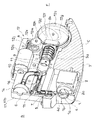
図1中、符号Cは車両用カメラを、符号Aは流体の吹き付け装置を示している。図示の例では、車両用カメラCは、符号3で示すケーシング内に、符号2で示すカメラ本体を内蔵させた構造となっている(なお、各図においては、車両用カメラCにおけるカメラ本体2以外の内蔵部品の図示は省略している。)。車両用カメラCは、前後方向xに長く、上下方向zを厚さとし、後方に向かうに連れて左右方向yの幅を漸増させ、後端面4に円形の前記入光部1を備えている。入光部1は前記カメラ本体2のレンズ部2aの後方に位置され、円形の穴1aを、光を通過させるシールド1bで塞いだ構造となっている。前記後端面4は、車室側に位置される第一面4aと、それより外側でかつ前方に位置される第二面4bとを有し、入光部1は第二面4bに形成されている。第一面4aと第二面4bとの間には段差面4cが形成されている。段差面4cと第二面4bとが接し会う箇所には、流体の吹き付け装置Aの吐出部7にチューブ5を介して連絡された吹き出し孔4dが形成されており、流体の吹き付け装置Aの吐出部7から吐出された流体は前記吹き出し孔4dを通じて前記入光部1に吹き付けられるようになっている。図示のようなシールド1bがなく、車両用カメラCを構成するカメラ本体2のレンズ部2aがケーシング3の外側に露出する構成の場合、入光部1はレンズ部2aそのものとなる。
In FIG. 1, reference numeral C indicates a vehicle camera, and reference numeral A indicates a fluid spraying device. In the illustrated example, the vehicle camera C has a structure in which the camera body indicated by the
前記流体の吹き付け装置Aは、
(1)前記流体の吸入部6と、
(2)前記流体の吐出部7と、
(3)前記吸入部6と前記吐出部7とを連絡する流路8と、
(4)ピストン9の前方の圧力室10(ピストン9の移動により容積を変化させるシリンダ11内の空間)を前記流路8に連通させたシリンダ11と、
(5)モータ12aを含んだ前記ピストン9の駆動機構12と、
(6)前記吸入部6と、前記圧力室10と前記流路8との連通箇所13との間にあって前記ピストン9の後退時には開弁して前記流路8を開放し、前記ピストン9の前進時には閉弁して前記流路8を閉鎖するように機能する第一バルブ14と、
(7)前記圧力室10と前記流路8との連通箇所13と、前記吐出部7との間にあって前記ピストン9の前進によって前記圧力室10の圧力が所定値になったときに開弁して前記流路8を開放するように機能する第二バルブ15と、
(8)これらを納めると共に、前記吐出部7から吐出される流体が車両用カメラCの入光部1に吹き付けられるように前記車両カメラに組み合わされるケーシング17とを備えてなる。
The fluid spraying device A
(1) The
(2) The
(3) A flow path 8 connecting the
(4) A
(5) The
(6) Located between the
(7) The valve is opened when the pressure in the
(8) In addition to accommodating these, the
図示の例では、前記流体としてのエアを前記吸入部6から吸入し、前記吐出部7から入光部1に吹き付ける構成となっている。前記流体は、洗浄液とすることも可能であり、また、エアに洗浄液を混合させたものとすることも可能である。
In the illustrated example, the air as the fluid is sucked from the
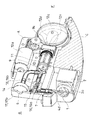
図示の例では、流体の吹き付け装置Aは、前後方向xに長く、左右方向yに短く、上下方向zを厚さとした扁平のケーシング17に前記(1)〜(7)の要素を内蔵させてなる。
In the illustrated example, the fluid spraying device A has the elements (1) to (7) built in a
図示の例では、流体の吹き付け装置Aは、そのケーシング17の長さ方向に沿った一方の厚さ側側面17aを、車両用カメラCのケーシングにおける車室側に位置される側面3aに接し合わせるようにして、車両用カメラCに組み合わされるようになっている。
In the illustrated example, the fluid spraying device A brings one
また、図示の例では、流体の吹き付け装置Aのケーシング17は、その厚さ方向の中程の位置で分離可能な、ロア部17bとアッパー部17cとを組み合わせてなる。
Further, in the illustrated example, the
前記ピストン9は、前後方向xに沿って、移動するようになっている。
The
図4に示されるように、前記吸入部6は、前記ピストン9の中心軸を含む仮想の中心線L1を挟んだ前記車両用カメラCの組み合わせ側と反対の側であって、前記中心線L1に直交し且つ前記圧力室10と前記流路8との連通箇所13を通る仮想の直線L2よりも後方Bとなる領域に備えられている。
As shown in FIG. 4, the
前記吐出部7は、前記中心線L1を挟んだ前記車両用カメラCの組み合わせ側であって、前記直線L2よりも後方Bとなる領域に備えられている。
The
前記流路8は、前記中心線L1に沿った中央流路8aを有している。中央流路8aの断面積は圧力室10の断面積より小さく、中央流路8aはその前端において圧力室10に連通している。すなわち、この中央流路8aの前端が前記圧力室10と前記流路8との連通箇所13となっている。
The flow path 8 has a central flow path 8a along the center line L1. The cross section of the central flow path 8a is smaller than the cross section of the
吸入部6は、ケーシング17の後端面17dに形成されている。吸入部6と中央流路8aとは、第一側方流路8bによって連絡されている。第一側方流路8bは、その後端を前記吸入部6とし、その前端8cを前記中央流路8aの前端(連通箇所13)よりもやや後方Bとなる位置において中央流路8aに連絡させている。
The
第一バルブ14は、前記第一側方流路8b内に形成されている。第一バルブ14を構成するボディ部14aは、第一側方流路8bの一部となる拡径室であり、第一バルブ14を構成する弁体14cは、このボディ部14a内に前後動可能に納められている。ボディ部14aにおける後方内壁14bとケーシング17の後端面17dとの間に形成された貫通穴が前記吸入部6として機能し、ボディ部14aにおける後方内壁14bが弁座として機能するようになっている。弁体14cは、円板状をなす頭部14dと、この頭部14dの前側の中央より前方に突き出す脚部14eとを有している。弁体14cは、前記吸入部6としての貫通穴より大径の頭部14dをボディ部14a内に位置させ、脚部14eをボディ部14aと第一側方流路8bの前端8c間にある第一側方流路8bの細径部8dに挿入させた状態で、第一側方流路8b内に位置している。前記ピストン9の後退時、図示の例では、ピストン9が前方Fに移動し圧力室10の容積が拡大していくとき、圧力室10の圧力変化により、第一バルブ14を構成する弁体14cは前方Fに移動して前記ボディ部14aの弁座としての後方内壁14bから離れ吸入部6は開放されて第一側方流路8bと中央流路8aを通じて圧力室10内に外気が引き込まれるようになっている。一方、前記ピストン9の前進時、図示の例では、ピストン9が後方Bに移動し圧力室10の容積が減少していくとき、圧力室10の圧力変化により、第一バルブ14を構成する弁体14cは後方Bに移動して前記ボディ部14aの弁座としての後方内壁14bに密着し吸入部6は閉鎖されるようになっている。すなわち、第一バルブ14は一方向弁となっている。
The
前記シリンダ11は、前記直線L2より前方Fとなる領域に備えられている。
The
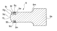
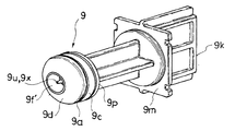
一方、前記ピストン9の側部9aには、前記中心軸xを周回する周回溝9bが形成されていると共に、この周回溝9bを利用してピストン9とシリンダ11との間をシールするシールリング9cが装着されている(図7、図8参照)。
On the other hand, the
それと共に、前記ピストン9の前記圧力室10に臨んだ前端部9dと前記周回溝9bにおける前記シールリング9cの内側に位置される箇所9eとの間には連絡路9f(通気路)が形成されている。
At the same time, a connecting
図示の例では、ピストン9は、その前端部9d側を、シリンダ11の内径よりもやや小径の短寸円柱状部9hによって構成させている。前記周回溝9bは、この短寸円柱状部9hの側部に形成されている。前記シールリング9cの外径はシリンダ11の内径と実質的に等しく、内径は短寸円柱状部9hの外径よりやや小さくなっている。
In the illustrated example, the
前記連絡路9fは、ピストン9の中心軸を巡る方向において隣り合う連絡路9fとの間に等しい間隔を開けて三箇所に設けられている。各連絡路9fはいずれも前記中心線L1に平行をなすように続く貫通穴となっている。
The connecting
ピストン9の前進時(往動時)は、連絡路9fによって圧力室10同様シールリング9c内方の周回溝9b内の圧力も高まることから、シールリング9cは外径を拡大する向きに弾性変形され、ピストン9とシリンダ11の内壁11aとの間のシール性が高められる。
When the
一方、ピストン9の後退時(復動時)は、連絡路9fによって圧力室10同様シールリング9c内方の周回溝9b内の圧力も低下することから、シールリング9cは外径を縮小する向きに弾性復帰され、ピストン9の後退時にはシールリング9cとシリンダ11の内壁11aとの間にできるだけ抵抗が生じないようにしてある。これにより、ピストン9の後退には過大な力を要しないようになっている。
On the other hand, when the
また、この実施の形態にあっては、前記ピストン9の前端部9dには傾斜面9iが形成されており、この傾斜面9iに前記連絡路9fの入り口9gを形成させている。図示の例では、前記前端部9dは、中央にピストン9の中心軸に直交する頂面9jを有すると共に、この頂面9jとピストン9の側部9aとの間を、頂面9jの側を傾斜上とする周回状をなす傾斜面9iとしている。これにより、連絡路9fの入り口9gの面積を、その余の箇所の断面積に比較して大きくして、ピストン9の前進時に連絡路9fに効果的にエアを取り込めるようになっている。
Further, in this embodiment, an
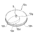
前記ピストン9の駆動機構12は、前記ピストン9を後退方向に付勢する付勢手段12bと、前記付勢により前記ピストン9の後端部9kが当接するカム部12dを備えると共に前記モータ12aにより回転駆動される回転体12cとを備えたものとなっている。そして、前記回転体12cの回転時に前記カム部12dの形状によって前記ピストン9を前後動させるようにしている。
The
図示の例では、前記駆動機構12を構成するモータ12aは、前記中心線L1を挟んだ前記車両用カメラCの組み合わせ側と反対の側において前記ピストン9に並ぶように配されている。
In the illustrated example, the
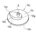
前記回転体12cは、前記ピストン9におけるシリンダ11から前方Fに突き出した後端部9kと、ケーシング17の前端面17eとの間に、前記中心線L1上においてその回転軸Sを上下方向zに沿わせるようにして配されている。
The
図示の例では、モータ12aの出力軸と一体化されたウォーム12jに噛み合うギア12kと、回転体12cの外周に形成されたギア部12hに噛み合うギア12mとを、かみ合わせることで、モータ12aの駆動により回転体12cが回転されるようになっている。
In the illustrated example, the
回転体12cの一面、図示の例では下面12iに、カム部12dが形成されている。カム部12dは回転体12cの下面12iから突出した形態となっており、回転体12cの下面12iとの間に周回段差面としてのカム面12eを形成させている。カム面12eは回転体12cの回転軸Sとの距離を最大とする第一部分12fと、回転体12cの回転軸を挟んで第一部分12fと反対の側に位置する第二部分12gとを有している。
A
前記付勢手段12bは、図示の例では、圧縮コイルバネとなっている。もっとも、かかる付勢手段12bはピストン9を後退方向に付勢可能なものであれば足り、圧縮コイルバネ以外の各種のバネやバネと同じような反発力を発揮する弾性体を用いて構わない。バネの一端は、シリンダ11の圧力室10側と反対の開口を巡る部分に形成された段差11bに圧接され、バネの他端はピストン9の前端部9dと後端部9kとの間に形成された鍔部9mに圧接されている。
The urging means 12b is a compression coil spring in the illustrated example. However, the urging means 12b suffices as long as it can urge the
ピストン9の後端部9kは、図示の例では、上下方向zを厚さとした板状をなし、回転体12cの下面12i下に入り込んで前記カム部12dのカム面12eに前記付勢手段12bの付勢により常時圧接されるようになっている。
In the illustrated example, the
回転体12cがカム面12eの第二部分12gをピストン9の後端部9kに圧接させる回転位置にあるときは、前記圧縮コイルバネの付勢によりピストン9は最も後退した位置となるようになっている。一方、回転体12cがカム面12eの第一部分12fをピストン9の後端部9kに圧接させる回転位置にあるときは、ピストン9は最も前進した位置となり、前記圧縮コイルバネは最も圧縮された状態となる。
When the
ピストン9の前進は回転体12cの回転によるカム部12dの作用によりなされ、ピストン9の後退は回転体12cの回転に伴った付勢手段12bの作用によりなされる。ピストン9の往復動にクランクシャフトを用いた場合に比べ上下死点がなく、回転体12cがどの回転位置にあってもモータ12aの駆動と同時に円滑にピストン9を動作させることが可能となっている。また、前記ピストン9の連絡路9fによりピストン9の後退には過大な力を要しないようになっていることから、前記付勢手段12bの付勢力は最小化することができ、したがって、ピストン9の前進時のモータ12aの負荷も最小化することができる。
The forward movement of the
また、前記第二バルブ15は、前記中央流路8a内に形成されている。
Further, the
前記第二バルブ15は、
前記吐出部7側に位置される大径室15aと、前記圧力室10側に位置される小径室15bとを有し、前記大径室15a内における前記小径室15bとの連通箇所を弁座15cとしたボディ部15’と、
弁頭部15iを前記大径室15a内に位置させると共に、前記弁頭部15iから延び出す軸部15jを前記小径室15bに挿入させた弁体15hと、
前記ピストン9の前進によって前記圧力室10の圧力が所定値になるまで前記弁体15hを前記弁頭部15iを前記弁座15cに密着させる閉弁位置に保持する保持手段16と、
を備えている。
The
It has a large-
A
A holding means 16 for holding the
Is equipped with.
また、前記弁体15hの前記軸部15jの外径と前記小径室15bの径とは実質的に等しくなっていると共に、前記軸部15jの側部に前記軸部15jの長さ方向に沿ってその全長に亘る一条の溝15k(通気溝)を形成させている。
Further, the outer diameter of the
図11及び図12に示されるように、図示の例では、ボディ部15’は、主体部15dとキャップ15eとを組み合わせてなる。主体部15dは、前記中心線L1に沿うように形成された小径室15bを前方Fに、その後方Bに大径室15aを有し、大径室15aの側部には前記中心線L1に直交する向きに延びる管部15fが連通されており、この管部15fの先端が前記吐出部7として機能するようになっている。弁座15cは大径室15aと小径室15bとの寸法差により形成された主体部15d内の段差面となっており、大径室15aに臨んだ大径室15aと小径室15bとを連通させる開口を巡っている。この弁座15cとの間に大径室15aを形成させるようにして、主体部15d内に弁体15hを納めた後に主体部15dにキャップ15eを組み合わせている。
As shown in FIGS. 11 and 12, in the illustrated example, the body portion 15'is formed by combining the
弁体15hは、円板状をなす弁頭部15iと、この弁頭部15iの一面側の中央から前方Fに突き出す筒状の軸部15jとを有している。弁頭部15iの外径は大径室15aに納まるが小径室15bには入り込まない大きさとなっている。弁体15hは、前記弁頭部15iを大径室15a内に位置させ、前記軸部15jを小径室15b内に差し込んだ状態で、前後動可能にボディ部15’内に保持される。図示の例ではまた、軸部15jの基部には弁頭部15iの一部をなすシールリング15mが嵌め付けられており、前記弁座15cにはこのシールリング15mで接するようになっている。
The
この実施の形態にあっては、前記ピストン9の前進によって前記圧力室10の圧力が所定値になるまで前記弁体15hを前記弁頭部15iを前記弁座15cに密着させる閉弁位置に保持手段16により保持するようになっている。
In this embodiment, the
前記圧力室10の圧力が所定値となると前記保持手段16による保持が解かれ、前記弁体15hは開弁位置、図示の例では、後方Bに移動し、圧縮されたエアが吐出部7を通じて吹き出される。かかる開弁状態において、ボディ部15’の小径室15bのエアの通過箇所は、弁体15hの軸部に形成された一条の溝15kに実質的に限定されることから、吐出されるエアの流速は効果的に高められる。
When the pressure in the
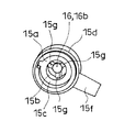
この実施の形態にあっては、前記保持手段16を、磁石及びこの磁石が吸着される強磁性材の一方を前記弁体15h側に、他方を前記ボディ部15’側に備えさせてなるものとしている。
In this embodiment, the holding means 16 is provided with one of the magnet and the ferromagnetic material to which the magnet is attracted on the
図示の例では、第一円柱状体16aを弁体15hの軸部15j内にこの第一円柱状体16aの端面が軸部15jの先端と同面になるようにしてはめ込んでいる。
In the illustrated example, the first columnar body 16a is fitted into the
また、ボディ部15’の小径室15b内に第二円柱状体16bをはめ込んでいる。図示の例では、小径室15b内には、前記中心線L1に沿う向きに続くリブ15gがこの中心線L1を巡る方向において隣り合うリブ15gとの間を中央流路8aの一部をなす連絡路とするようにして三箇所形成されている。この三箇所のリブ15gの先端間を利用して小径室15b内に第二円柱状体16bをはめ込ませている。第二円柱状体16bの端面は閉弁位置において弁体15hの軸部15jの先端が位置される箇所に位置されている。
Further, the second columnar body 16b is fitted in the
第一円柱状体16a及び第二円柱状体16bの一方が磁石とされ、他方が強磁性材となっている。 One of the first columnar body 16a and the second columnar body 16b is a magnet, and the other is a ferromagnetic material.
これにより、この実施の形態にあっては、前記ピストン9の前進によって前記圧力室10の圧力が所定値になるまでは前記弁体15hを前記弁頭部15iを前記弁座15cに密着させる閉弁位置に保持手段16により保持し、前記圧力室10の圧力が所定値を越えた瞬間に前記弁体15hを開弁位置に移動させて圧力室10内のエアを所定の流速をもって吐出部7から吹き出させることができるようになっている。また、一回のエアの吹き出しが終了したときは、磁石の吸着力により直ちに前記弁体15hを閉弁位置に移動させることができる。
As a result, in this embodiment, the
この実施の形態にかかる流体の吹き付け装置Aは、前述のようにピストン9の前進時のモータ12aの負荷が最小化され、吹き出されるエアの流速を効率的に高められる構造を備えていることから、ピストン9、シリンダ11、モータ12aを支障少なく可及的に小型化可能であり、もって流体の吹き付け装置Aの全体としての小型化に寄与する特長を有している。
As described above, the fluid spraying device A according to this embodiment has a structure in which the load on the
この実施の形態にかかる流体の吹き付け装置Aは、ケーシング内に車両用カメラCの入光部1にエアを吹き付ける機能を全て納めたユニットとなっており、車両カメラに組み合わせることで、この車両用カメラCないしはこの車両用カメラCを備える車両に対し前記入光部1に付着した水滴や塵埃などを取り除く機能を容易且つ確実に付加させることができる。
The fluid spraying device A according to this embodiment is a unit in which all the functions of blowing air to the
図14〜図16に示される例は、図1〜図13に示される例のピストンの構成変更例(以下、第二例と称する。)を示している。この第二例では、前記図1〜図13に示される例の連絡路9fに対応する連絡路9f’は、ピストン9の中心軸を巡る方向において隣り合う連絡路9f’との間に等しい間隔を開けて四箇所に設けられている。各連絡路9f’はいずれも前記中心線L1に平行をなすように続く貫通穴となっている。
The examples shown in FIGS. 14 to 16 show examples of changing the piston configuration (hereinafter, referred to as a second example) of the examples shown in FIGS. 1 to 13. In this second example, the connecting paths 9f'corresponding to the connecting
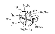
前記第二例では、前記ピストン9は、前記圧力室10に臨んだ前端部9dと、前記前端部9dの後方に位置される首部9oと、前記首部9oの後方に位置される胴部9pとを備えている。そして、前記首部9oを利用して、前記ピストン9の側部にシールリング9cが装着されている。
In the second example, the
前記第二例では、首部9oは、前端部9dと胴部9pとをつなぐと共に、前端部9d及び胴部9pの外径よりもやや直径を小さくする仮想の円rの円弧上に位置される前記シールリング9cの支持部分9qを、ピストン9の中心軸を巡る向きにおいて隣り合う支持部分9qとの間に間隔を開けて四カ所備えている。各支持部分9qは首部9oの中心から放射方向に突き出すリブ状部9rの外端9sによって形成されており、隣り合う支持部分9q間にはそれぞれ、シールリング9cと首部9oの中心との間に空間9uが形成されている。空間9uは四カ所形成され、各空間9uは同じ広さとなっている。
In the second example, the neck portion 9o is located on an arc of a virtual circle r that connects the
前記第二例にあっては、前記前端部9dと前記空間9uとの間に亘るように前記連絡路9f’が形成されており、四つの前記空間9uがそれぞれ、前記連絡路9f’を通じて圧力室10と連通されるようになっている。
In the second example, the connecting path 9f'is formed so as to extend between the
これにより、前記第二例にあっては、ピストン9の前進時(往動時)に、連絡路9f’によってシールリング9c内方の空間9uの圧力をシールリング9cの周方向における各位置において偏り少なく高めることができ、シールリング9cの外径をシールリング9cの周方向における各位置において偏り少なく拡大させることができるようになっている。
As a result, in the second example, when the
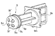
図17〜図19に示される例は、図1〜図13に示される例のピストン9の構成のさらに別の変更例(以下、第三例と称する。)を示している。この第三例では、前記第一例の連絡路9fに対応する前記連絡路9f’は、ピストン9の中心軸位置に形成されている。
The examples shown in FIGS. 17 to 19 show still another modified example (hereinafter, referred to as a third example) of the configuration of the
前記第三例では、前記ピストン9は、前記圧力室10に臨んだ前端部9dと、前記前端部9dの後方に位置される首部9oと、前記首部9oの後方に位置される胴部9pとを備えている。そして、前記首部9oを利用して、前記ピストン9の側部にシールリング9cが装着されている。
In the third example, the
前記第三例では、連絡路9f’内には、連絡路9f’の径よりも外径を小さくする柱部9vが位置されている。柱部9vは胴部9pに基部9wを一体化させて前記ピストン9の中心軸に沿って圧力室10側に突き出すように形成されている。柱部9vは先端9xに近づくに連れて次第に外径を細める断面円形の針状を呈していると共に、柱部9vと連絡路9f’の内面と間には前記ピストン9の中心軸を巡る各位置において略等しい間隔が形成されるようになっている。
In the third example, a
前記第三例では、首部9oは、前端部9dと胴部9pとをつなぐと共に、前端部9d及び胴部9pの外径よりもやや直径を小さくする仮想の円rの円弧上に位置される前記シールリング9cの支持部分9qを、ピストン9の中心軸を巡る向きにおいて隣り合う支持部分9qとの間に間隔を開けて四カ所備えている。各支持部分9qは前記柱部9v側から放射方向に突き出すリブ状部9rの外端9sによって形成されている。リブ状部9rの内端9tと柱部9vとの間には隙間が形成されている。隣り合うリブ状部9r間にはそれぞれ、シールリング9cと柱部9vとの間に空間9uが形成されている。空間9uは四カ所形成され、各空間9uは同じ広さとなっている。
In the third example, the neck portion 9o is located on an arc of a virtual circle r that connects the
前記第三例にあっては、前記のように形成された連絡路9f’によって、四つの前記空間9uがそれぞれ、前記圧力室10と連通されるようになっている。
In the third example, each of the four
これにより、前記第四例にあっては、ピストン9の前進時(往動時)に、連絡路9f’によってシールリング9c内方の空間9uの圧力をシールリング9cの周方向における各位置において偏り少なく高めることができ、シールリング9cの外径をシールリングの周方向における各位置において偏り少なく拡大させることができるようになっている。
As a result, in the fourth example, when the
なお、当然のことながら、本発明は以上に説明した実施態様に限定されるものではなく、本発明の目的を達成し得るすべての実施態様を含むものである。 As a matter of course, the present invention is not limited to the embodiments described above, but includes all embodiments that can achieve the object of the present invention.
C 車両用カメラ
1 入光部
6 吸入部
7 吐出部
8 流路
9 ピストン
10 圧力室
11 シリンダ
12 駆動機構
12a モータ
14 第一バルブ
15 第二バルブ
17 ケーシング
Claims (8)
流体の吐出部と、
前記吸入部と前記吐出部とを連絡する流路と、
ピストンの前方の圧力室を前記流路に連通させたシリンダと、
モータを含んだ前記ピストンの駆動機構と、
前記吸入部と、前記圧力室と前記流路との連通箇所との間にあって、前記ピストンの後退時には開弁し、前記ピストンの前進時には閉弁するように機能する第一バルブと、
前記圧力室と前記流路との連通箇所と、前記吐出部との間にあって、前記ピストンの前進によって前記圧力室の圧力が所定値になったときに開弁するように機能する第二バルブと、
これらを納めると共に、前記吐出部から吐出される流体が車両用カメラの入光部に吹き付けられるように前記車両用カメラに組み合わされるケーシングとを備えており、
しかも、前記ピストンは前後方向に移動するようになっていると共に、
前記ケーシングは、前後方向に長く、上下方向を厚さとした扁平であり、前記ケーシングの長さ方向に沿った一方の厚さ側側面を、前後方向に長く上下方向を厚さとし自動車の車室外に前記入光部を位置させる前記車両用カメラにおける車室側に位置される側面に接し合わせるようにして、前記車両用カメラに組み合わされるようにしてなる、車両用カメラに対する流体の吹き付け装置。 The fluid suction part and
The fluid discharge part and
A flow path connecting the suction unit and the discharge unit,
A cylinder that communicates the pressure chamber in front of the piston with the flow path,
The drive mechanism of the piston including the motor and
And the suction unit, be between the communicating portion between the flow path and the pressure chamber, opens during retraction of the piston, a first valve serving to closed during forward movement of the piston,
And communicating portion between said flow path and the pressure chamber, there between the discharge portion, and a second valve functioning to open when the pressure in the pressure chamber by advancing the piston has reached a predetermined value ,
In addition to accommodating these, it is provided with a casing that is combined with the vehicle camera so that the fluid discharged from the discharge unit is sprayed onto the light input portion of the vehicle camera .
Moreover, the piston moves in the front-rear direction and also
The casing is flat and long in the front-rear direction and thick in the vertical direction, and one side surface on the thickness side along the length direction of the casing is long in the front-rear direction and thick in the vertical direction to the outside of the passenger compartment of the automobile. A device for spraying fluid on a vehicle camera so as to be in contact with a side surface of the vehicle camera in which the light receiving portion is located and located on the vehicle interior side so as to be combined with the vehicle camera.
前記回転体の回転時に前記カム部の形状によって前記ピストンを前後動させるようにしてなる、請求項1に記載の車両用カメラに対する流体の吹き付け装置。 The driving mechanism of the piston includes a urging means for urging the piston in the backward direction, a cam portion with which the rear end portion of the piston comes into contact with the urging, and a rotating body rotationally driven by the motor. Prepare,
The fluid spraying device for a vehicle camera according to claim 1, wherein the piston is moved back and forth according to the shape of the cam portion when the rotating body rotates.
前記ピストンの前記圧力室に臨んだ前端部と前記周回溝における前記シールリングの内側に位置される箇所との間に連絡路を形成させてなる、請求項1又は請求項2に記載の車両用カメラに対する流体の吹き付け装置。 A circumferential groove is formed on the side portion of the piston, and a seal ring is mounted using the circumferential groove.
The vehicle according to claim 1 or 2, wherein a connecting path is formed between the front end of the piston facing the pressure chamber and a portion of the circumferential groove located inside the seal ring. A device that sprays fluid on the camera.
前記前端部と前記シールリングの内側に位置される箇所との間に連絡路を形成させてなる、請求項1又は請求項2に記載の車両用カメラに対する流体の吹き付け装置。 The piston includes a front end portion facing the pressure chamber, a neck portion located behind the front end portion, and a body portion located behind the neck portion, and the piston has the neck portion. The seal ring is attached using it,
The fluid spraying device for a vehicle camera according to claim 1 or 2, wherein a connecting path is formed between the front end portion and a portion located inside the seal ring.
前記吐出部側に位置される大径室と、前記圧力室側に位置される小径室とを有し、前記大径室内における前記小径室との連通箇所を弁座としたボディ部と、
弁頭部を前記大径室内に位置させると共に、前記弁頭部から延び出す軸部を前記小径室に挿入させた弁体と、
前記ピストンの前進によって前記圧力室の圧力が所定値になるまで前記弁体を前記弁頭部を前記弁座に密着させる閉弁位置に保持する保持手段と、
を備えており、
前記弁体の前記軸部の外径と前記小径室の径とは実質的に等しくなっていると共に、前記軸部の側部に前記軸部の長さ方向に沿った一条の溝を形成させてなる、請求項1〜請求項5のいずれか1項に記載の車両用カメラに対する流体の吹き付け装置。 The second valve is
A body portion having a large-diameter chamber located on the discharge portion side and a small-diameter chamber located on the pressure chamber side, and having a communication point with the small-diameter chamber in the large-diameter chamber as a valve seat.
A valve body in which the valve head is positioned in the large-diameter chamber and a shaft portion extending from the valve head is inserted into the small-diameter chamber.
A holding means for holding the valve body in a valve closing position where the valve head is brought into close contact with the valve seat until the pressure in the pressure chamber reaches a predetermined value due to the advancement of the piston.
Is equipped with
The outer diameter of the shaft portion of the valve body and the diameter of the small diameter chamber are substantially equal to each other, and a single groove is formed on the side portion of the shaft portion along the length direction of the shaft portion. The fluid spraying device for a vehicle camera according to any one of claims 1 to 5.
Priority Applications (4)
| Application Number | Priority Date | Filing Date | Title |
|---|---|---|---|
| CN201880007654.3A CN110191825B (en) | 2017-01-20 | 2018-01-05 | Fluid injection device for vehicle camera |
| US16/476,707 US11345319B2 (en) | 2017-01-20 | 2018-01-05 | Device for spraying fluid on vehicle camera |
| PCT/JP2018/000103 WO2018135322A1 (en) | 2017-01-20 | 2018-01-05 | Device for spraying fluid on vehicle camera |
| DE112018000461.9T DE112018000461T5 (en) | 2017-01-20 | 2018-01-05 | Apparatus for spraying a fluid on a vehicle camera |
Applications Claiming Priority (2)
| Application Number | Priority Date | Filing Date | Title |
|---|---|---|---|
| JP2017008155 | 2017-01-20 | ||
| JP2017008155 | 2017-01-20 |
Publications (3)
| Publication Number | Publication Date |
|---|---|
| JP2018118717A JP2018118717A (en) | 2018-08-02 |
| JP2018118717A5 JP2018118717A5 (en) | 2019-11-28 |
| JP6764385B2 true JP6764385B2 (en) | 2020-09-30 |
Family
ID=63044751
Family Applications (1)
| Application Number | Title | Priority Date | Filing Date |
|---|---|---|---|
| JP2017182228A Active JP6764385B2 (en) | 2017-01-20 | 2017-09-22 | Fluid spraying device for vehicle cameras |
Country Status (3)
| Country | Link |
|---|---|
| JP (1) | JP6764385B2 (en) |
| CN (1) | CN110191825B (en) |
| DE (1) | DE112018000461T5 (en) |
Families Citing this family (7)
| Publication number | Priority date | Publication date | Assignee | Title |
|---|---|---|---|---|
| WO2019044113A1 (en) * | 2017-08-30 | 2019-03-07 | 株式会社小糸製作所 | Vehicle cleaner unit, and vehicle provided with vehicle cleaner unit |
| JP6792534B2 (en) * | 2017-10-11 | 2020-11-25 | 株式会社ニフコ | Fluid discharge mechanism and fluid spraying device for vehicle cameras or sensors |
| JP7110755B2 (en) | 2018-06-22 | 2022-08-02 | コニカミノルタ株式会社 | Inkjet recording liquid set, method for producing pretreatment liquid for inkjet recording, printed matter and inkjet recording method |
| JP2020032821A (en) * | 2018-08-28 | 2020-03-05 | 本田技研工業株式会社 | Vehicular imaging unit arrangement structure |
| CN110935690B (en) * | 2019-11-28 | 2021-12-07 | 维沃移动通信有限公司 | Electronic device |
| DE102020132253A1 (en) | 2020-12-04 | 2022-06-09 | Zf Cv Systems Global Gmbh | Module housing, mirror replacement system, vehicle |
| DE102022112927A1 (en) | 2022-05-23 | 2023-11-23 | Webasto SE | Roof module for forming a vehicle roof with a cleaning device |
Family Cites Families (19)
| Publication number | Priority date | Publication date | Assignee | Title |
|---|---|---|---|---|
| JPS4033115Y1 (en) * | 1963-08-02 | 1965-11-19 | ||
| JPS5058622A (en) * | 1973-09-27 | 1975-05-21 | ||
| JPS5372229A (en) * | 1976-12-10 | 1978-06-27 | Shinei Seisakusho Kk | Pilot check valve |
| JPS53113951U (en) * | 1977-02-21 | 1978-09-11 | ||
| CN2154922Y (en) * | 1993-02-02 | 1994-02-02 | 丰余实业股份有限公司 | Piston leakage-proof ring of inflator |
| GB9925648D0 (en) * | 1999-10-29 | 1999-12-29 | Boc Group Plc | Improvements in valves |
| JP2005133744A (en) * | 2003-10-28 | 2005-05-26 | Wako Denshi Kk | Valve device |
| CN2660228Y (en) * | 2003-12-22 | 2004-12-01 | 王宗泽 | Strongly sealed piston |
| DE102008061311A1 (en) * | 2008-12-11 | 2010-06-24 | Doukas Ag | Device for conveying a gas |
| US8864392B2 (en) * | 2012-02-15 | 2014-10-21 | GM Global Technology Operations LLC | Camera system |
| CN203421237U (en) * | 2013-08-29 | 2014-02-05 | 彭中 | Fluid non-contact one-way valve |
| JP6417757B2 (en) | 2013-09-19 | 2018-11-07 | 株式会社デンソー | In-vehicle optical sensor cleaning device |
| EP3132984B1 (en) * | 2014-04-14 | 2019-11-20 | Koito Manufacturing Co., Ltd. | In vehicle device with foreign material removal |
| EP2949520B1 (en) * | 2014-05-27 | 2018-03-21 | Fico Transpar, S.A. | System for cleaning a vehicle-mounted optic lens |
| FR3027008B1 (en) * | 2014-10-10 | 2017-12-08 | Valeo Systemes Dessuyage | DEVICE FOR CLEANING A DRIVING CAMERA FOR DRIVING A MOTOR VEHICLE |
| JP6597334B2 (en) * | 2015-05-28 | 2019-10-30 | 株式会社デンソー | In-vehicle optical sensor cleaning device |
| JP6650125B2 (en) | 2015-06-18 | 2020-02-19 | Dic株式会社 | Polyester modified epoxy resin and adhesive |
| CN107709107B (en) * | 2015-06-30 | 2022-01-18 | 株式会社小糸制作所 | Foreign matter removing device and vehicle with same |
| JP6776578B2 (en) | 2016-03-29 | 2020-10-28 | セイコーエプソン株式会社 | Input device, input method, computer program |
-
2017
- 2017-09-22 JP JP2017182228A patent/JP6764385B2/en active Active
-
2018
- 2018-01-05 CN CN201880007654.3A patent/CN110191825B/en active Active
- 2018-01-05 DE DE112018000461.9T patent/DE112018000461T5/en active Pending
Also Published As
| Publication number | Publication date |
|---|---|
| CN110191825B (en) | 2022-08-30 |
| CN110191825A (en) | 2019-08-30 |
| DE112018000461T5 (en) | 2019-09-26 |
| JP2018118717A (en) | 2018-08-02 |
Similar Documents
| Publication | Publication Date | Title |
|---|---|---|
| JP6764385B2 (en) | Fluid spraying device for vehicle cameras | |
| WO2018135322A1 (en) | Device for spraying fluid on vehicle camera | |
| US10654451B2 (en) | System for cleaning on-vehicle optical sensor and method for the same | |
| US10738771B2 (en) | Electric pump and cleaning device for on-vehicle optical sensor | |
| JP6641369B2 (en) | Foreign matter removing device and vehicle equipped with the foreign matter removing device | |
| JP6263316B2 (en) | Integrated in-vehicle vehicle visibility and cleaning system | |
| JP6654430B2 (en) | Injection device and injection system | |
| JP6333465B2 (en) | Integrated vehicle vision and cleaning system | |
| JP6576686B2 (en) | In-vehicle optical surface cleaning device and cleaning system, and in-vehicle optical sensor having cleaning device | |
| JP2021508595A (en) | Cleaning and drying system for automobile image sensor surface | |
| JP6439589B2 (en) | In-vehicle optical sensor cleaning system and in-vehicle optical sensor cleaning method | |
| US10587784B2 (en) | Cleaner and vehicle with cleaner | |
| US20190084530A1 (en) | Vehicle cleaning apparatus | |
| JP6792534B2 (en) | Fluid discharge mechanism and fluid spraying device for vehicle cameras or sensors | |
| CN111051157A (en) | Foreign matter removing device | |
| US20190145411A1 (en) | Gas ejection apparatus | |
| JP2020152326A (en) | Cleaning equipment for vehicle | |
| JP2016217250A (en) | air pump |
Legal Events
| Date | Code | Title | Description |
|---|---|---|---|
| A521 | Request for written amendment filed |
Free format text: JAPANESE INTERMEDIATE CODE: A523 Effective date: 20191017 |
|
| A621 | Written request for application examination |
Free format text: JAPANESE INTERMEDIATE CODE: A621 Effective date: 20191017 |
|
| A131 | Notification of reasons for refusal |
Free format text: JAPANESE INTERMEDIATE CODE: A131 Effective date: 20200630 |
|
| A521 | Request for written amendment filed |
Free format text: JAPANESE INTERMEDIATE CODE: A523 Effective date: 20200817 |
|
| TRDD | Decision of grant or rejection written | ||
| A01 | Written decision to grant a patent or to grant a registration (utility model) |
Free format text: JAPANESE INTERMEDIATE CODE: A01 Effective date: 20200908 |
|
| A61 | First payment of annual fees (during grant procedure) |
Free format text: JAPANESE INTERMEDIATE CODE: A61 Effective date: 20200911 |
|
| R150 | Certificate of patent or registration of utility model |
Ref document number: 6764385 Country of ref document: JP Free format text: JAPANESE INTERMEDIATE CODE: R150 |
|
| R250 | Receipt of annual fees |
Free format text: JAPANESE INTERMEDIATE CODE: R250 |