EP3580743B1 - Rahmenständer für poster - Google Patents
Rahmenständer für poster Download PDFInfo
- Publication number
- EP3580743B1 EP3580743B1 EP17704233.0A EP17704233A EP3580743B1 EP 3580743 B1 EP3580743 B1 EP 3580743B1 EP 17704233 A EP17704233 A EP 17704233A EP 3580743 B1 EP3580743 B1 EP 3580743B1
- Authority
- EP
- European Patent Office
- Prior art keywords
- frame
- base plate
- cover frame
- latch
- frame stand
- Prior art date
- Legal status (The legal status is an assumption and is not a legal conclusion. Google has not performed a legal analysis and makes no representation as to the accuracy of the status listed.)
- Active
Links
Images


Classifications
-
- G—PHYSICS
- G09—EDUCATION; CRYPTOGRAPHY; DISPLAY; ADVERTISING; SEALS
- G09F—DISPLAYING; ADVERTISING; SIGNS; LABELS OR NAME-PLATES; SEALS
- G09F15/00—Boards, hoardings, pillars, or like structures for notices, placards, posters, or the like
- G09F15/0006—Boards, hoardings, pillars, or like structures for notices, placards, posters, or the like planar structures comprising one or more panels
- G09F15/0056—Boards, hoardings, pillars, or like structures for notices, placards, posters, or the like planar structures comprising one or more panels portable display standards
- G09F15/0062—Boards, hoardings, pillars, or like structures for notices, placards, posters, or the like planar structures comprising one or more panels portable display standards collapsible
-
- G—PHYSICS
- G09—EDUCATION; CRYPTOGRAPHY; DISPLAY; ADVERTISING; SEALS
- G09F—DISPLAYING; ADVERTISING; SIGNS; LABELS OR NAME-PLATES; SEALS
- G09F15/00—Boards, hoardings, pillars, or like structures for notices, placards, posters, or the like
- G09F15/0006—Boards, hoardings, pillars, or like structures for notices, placards, posters, or the like planar structures comprising one or more panels
- G09F15/0012—Boards, hoardings, pillars, or like structures for notices, placards, posters, or the like planar structures comprising one or more panels frames therefor
Definitions
- the invention relates to a frame stand for posters, especially a V-shape or an A-shape stand frame.
- Display frames are widely used in advertisement, announcement, traffic signs, safety warnings, information bulletins, etc.
- a displaying sheet (such as a poster, a sign, a picture, an information sheet, etc.) is attached or inserted in the display frame. And most of the time, the displaying sheet therein needs to be changed from time to time according to different scenarios.
- the "poster” is used hereafter as a sample of the displaying sheet which is not limited to pictures or photos but also cover any instructing signs, document sheets, and so on.
- a frame stand which can stand on the ground by itself after assembly, is widely used, because it is easy to be put into use at any place.
- V-shape frame stands and A-shape frame stands are popular.
- a V-shape frame stand may comprise two frames connected together and appears as an inverted "V" when deployed.
- the two frames are connected to each other at one end by one or more hinges, permitting the two frames to be folded flat for transportation or storage, and permitting the two frames to be configured in the shape of an inverted "V" when deployed.
- the frames may have legs to stand on the ground.
- An A-shape frame stand is similar to the V-shape frame stand, except that a connecting member is placed on the middle or lower part between the two frames.
- This connecting member may be either a rigid member (like a bar or a rod) or a flexible member (like a rope or a cord or a chain or a strap).
- A-shape frame stand two frames are connected via hinges disposed along the top of the respective panels, and the lower portions of the frame can be spread apart.
- a flexible member is connected between adjacent legs on opposing frames, the flexible member being dimensioned such that the maximum angle between the frames of the sign stand can be restricted.
- A-shape frame stands can be seen in US 2075401 , US6615523 B1 or US 6131320 .
- US 20110239506 A1 discloses a V-shape frame stand, which has advantages like simple constructions and easy manipulations. However, it also has disadvantages. For example, the poster in display is liable to be contaminated by water and dust. Besides, the size of the poster suitable to be inserted into the frame is limited. It can be expected that only a poster with designated size can be directly inserted into the panel. When the size of the poster is smaller than the displaying area, extra tapes or adhesive would probably be needed to attach the poster on the frame.
- US2075401 discloses an A-shape frame stand which comprises a removable frame (17, 18) by which the poster is held in place.
- posters can be held in a taut position to present a good appearance.
- the posters may be held for display without need of employing any adhesive.
- its manipulation is relatively troublesome, especially when two end bars 18 have to be aligned and inserted into the recesses 16 of the base plate.
- a frame stand for posters comprising two frames is known from US 1,487,500 .
- the bottom edges of the two frames are connected with each other by a hinge.
- Each frame comprises a plurality of eyelets at the top.
- a rod can be inserted through the eyelets.
- Further stands comprising frames or plates which are are connected with each other by a hinge are known from the documents DE 203 15 284 U1 , US 2,454,648 and US 2,073,403 .
- a frame stand for posters according to the main claim comprises a base plate and a cover frame.
- the cover frame has a bottom edge which is rotatable connected to the base plate. The bottom edge is the edge at the bottom when the frame stand stands on a ground in the intended manner.
- the base plate as well as the frame can be formed from plastic or a metal like aluminum.
- the cover frame can be moved between a closed and an opened position. It is possible to grip a top portion of the frame in order to move the frame by hand which facilitates the handling. Top portion means a portion at the top of the cover frame when the frame stand stands on a ground in the intended manner.
- a poster In the opened position, a poster can be inserted between the base plate and the cover frame from the top and thus in an easy and reliable manner. In the closed position, an inserted poster can be held by the base plate and the cover frame in a reliable manner.
- the frame stand comprises a locking mechanism at the top for the cover frame.
- “Top” refers to the situation when the frame stand stands on a ground in the intended manner.
- the locking mechanism comprises a locking element to lock the cover frame and the base plate together.
- the locking mechanism can lock the cover frame in its closed position. It is not possible to move the cover frame to the opened position, when the cover frame is locked in its closed position.
- the locking element is capable of locking the upper edge of the cover frame with the base plate in order to facilitate the handling.
- the locking mechanism is arranged adjacent to a handle of the frame stand. This makes it easier to unlock the locking mechanism.
- a groove is provided in the upper portion of the base plate, and the groove is so arranged that an inner edge of the upper edge of the cover frame can be inserted into the groove for stability reasons.
- the locking element comprises a latch which has a projection suitable to be inserted into a slot of the upper edge of the cover frame.
- the above mentioned inner edge of the upper edge comprises the slot which allows arranging the locking mechanism in a more appropriate manner so that the handling is convenient.
- one end of the latch can move upwardly or downwardly when the frame stand stands on a ground. Due to this embodiment, it is very easy to lock and/or to unlock the locking mechanism.
- the latch is mounted in rotatable manner.
- one end of the latch is mounted in rotatable manner in order to facilitate the handling of the locking mechanism.
- the locking mechanism comprises a pre-stressed spring which can move the locking mechanism into its locked position and/or which can hold the locking mechanism in its locked position.
- the locking mechanism comprises a grip bar which is attached to a latch.
- the grip bar is bent forward or backward relative to the latch and/or the latch and the grip bar forms angle of preferably 90°. The grip facilitates the handling of the locking mechanism.
- a hole is provided on the top portion of the base plate to form a handle for the frame stand, and the hole is so adapted that a user's hand can pass through the hole to lift the latch.
- the locking mechanism is covered by at least one plate and thus well-protected. On the other side, it is easy to lock or to unlock the locking mechanism.
- the base plate comprises a circumferential projection which surrounds the cover frame when the cover frame is in its closed position.
- the outer surfaces of the circumferential projection and the cover frame are flush with each other when the cover frame is in its closed position or the circumferential projection stands out against the cover frame.
- the cover frame is well-protected.
- the cover frame surrounds a transparent plate.
- the plate can protect an inserted poster in addition.
- the plate can held the poster in addition and thus a more reliable manner independent from the size of the poster.
- the transparent plate can be formed from plastic or glass.
- the base plate has an inclined display surface when the frame stand stands on the ground.
- the cover frame can remain in its closed position only due to gravity. This further facilitates the handling of the frame stand.
- the frame stand is an A- or a V-shape frame stand.
- the frame stand may comprise two base plates or the above mentioned base plate and a base frame. Such a stand can stand on a ground in a very stable manner.
- the two base plates respectively the base plate and the base frame can be connected together by a hinge.
- the base plates respectively the base plate and the base frame can swing out to present an inverted "V" or an A.
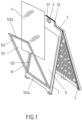
- FIG. 1 A detailed embodiment of the present invention is illustrated in Fig. 1 .
- a V-shape frame stand comprises two frames 1 and 2, which form an inverted "V" when deployed.
- the two frames 1 and 2 are hinged on the upper part.
- the two frames 1 and 2 are made of an artificial material and molded in such a shape that the hinge elements on the upper parts of the two base plates can be engaged together, by which the frame stand can be folded or deployed.
- hinge elements are integrally molded with the frames.
- extra accessories such as metal axis to connect the molded hinge elements may be used.
- the first frame 1 surrounds a base plate 11.
- the second frame may also surround a base plate for example for stability reasons.
- each frame 1 comprising the base plate 11 and hinge elements are preferably made in one piece as shown in the figures.
- Figure 1 shows the frame stand standing on a ground in an intended manner.
- a top portion 31 and 32 is provided on top of the frames 1 and 2 respectively, and located above the hinge elements.
- Each top portion 31 or 32 has preferably two side edges of an acute angle.
- each top portion 31 and 32 comprises a hole 5, so that the top portions 31 and 32 comprise a handle for the V-shape frame stand.
- the holes 5 form a handle.
- the frame 1 includes a base plate 11 and a cover frame 12.
- the cover frame 12 comprises a transparent plate 121 and a peripheral frame 122 surrounding the transparent plate 121.
- the base plate 11 may be made of plastic, metal, wood or other materials known in the art.
- the transparent plate 121 can be made of plastic material like PMMA.
- a glass plate can be also used as the transparent plate, however, glass is not preferred if the frame stand has to be moved frequently, since the weight of glass is relatively heavy.
- the peripheral frame 122 surrounding the transparent plate 121 is preferred to be a metal frame, for example, made of stainless steel, aluminum, or aluminum alloy.
- the bottom edge 122a of the cover frame 12 is rotatable connected to the base plate 11 or the frame 1, so that the cover frame 12 can pivot around an axis located at the bottom part of the base plate 11.
- the frame 1 forms a circumferential projection 125 which surrounds the cover frame 12 when the cover frame 12 is in its closed position.
- the outer surfaces of the circumferential projection 125 and the cover frame are flush with each other when the cover frame is in its closed position (see Fig. 2b ).
- the circumferential projection 125 stands out against the cover frame 12 when the cover frame 12 is in its closed position. As a result, the cover frame is well-protected in its closed position.
- a poster 4 can be inserted into the frame stand.
- the frame 2 has a similar structure compared with the frame 1, namely also comprising a base plate 21 and a cover frame 22, wherein the bottom edge 222a of the cover frame 22 is rotatable connected to the base plate 21.
- An example of this embodiment can be seen in Fig. 2a .
- Fig. 2a illustrates a frame stand with an opened cover frame and showing how to insert a poster 4 into the frame stand.
- Fig. 2b illustrates a frame stand with closed cover frame.
- a process of inserting a poster into the frame stand can be as follows.
- the cover frame 12 is rotated outwardly, so that the receptacle to receive the poster is open.
- the cover frame 12 is the in its opened position.
- the poster 4 is inserted and spread on the base plate 11 of the frame 1.
- the cover frame 12 is rotated inwardly.
- the upper edge 122b of the cover frame 12 comes into contact with the base plate 11, a closed status is achieved.
- the cover frame is in its closed position.
- the poster therein can be removed or changed.
- FIG. 2c A preferred embodiment is presented in Fig. 2c .
- the groove 30 is so arranged that an inner edge 123 of the upper edge 122b of the cover frame 12 can be inserted into the groove 30, to keep the cover frame 12 in a closed status and stable position. Further, this embodiment allows locking the cover frame 12 in its closed position in a simple and convenient manner.
- a locking element is provided to lock the cover frame 12 and the frame 1 together, and thus further restrain the cover frame 12 from rotating.
- a locking element is capable of locking the upper edge 122a of the cover frame 12 with the frame 1. More preferably, the locking element can be moved into a slot of the inner edge 123 for locking the cover frame in a simple and convenient manner.
- stepped profile 124 provided at the outside of the upper edge 122b of the cover frame 12.
- the stepped profile 124 can work as a grip which facilitates opening and closing the cover frame.
- Fig. 3 shows an exemplary structure of the pivot portion to achieve the above function.
- the bottom edge 122a of the peripheral frame 122 has an almost rectangular profile so that a female pivoting member 21 is provided at the inner side of the cover frame 12.
- the female pivoting member 21 matches with the male pivoting member 22 of the bar 23 so that the female pivoting member 21 can pivot around the axis of the male pivoting member 22.
- the bar 23 is fixed to the base plate 11 respectively the fram1 1 by a fastener 24, for example, a screw fastener.
- the bar 23 may have the form of a rail which can hold the fastener 24 in a displaceable manner.
- a groove 20 is formed adjacent to the bottom part of the base plate 11, and many components including the bottom edge 122a, the female pivoting member 21, the male pivoting member 22, the bar 23, a portion of the fastener 24, etc., are located in the groove 20. These parts are on one side well-protected. On the other side, these parts are nearly invisible.
- the male pivoting member 22 is an integrated part of the molded base plate 11.
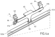
- Fig. 4a is an enlarged partial perspective view showing the locking element in the locked position.
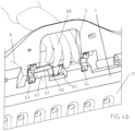
- Fig. 4a is an enlarged partial perspective view showing how to unlock the locking mechanism.
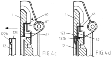
- Fig. 4c and Fig. 4d are enlarged partial cut views showing the locking element in the unlocked and locked position.
- Fig. 4a to Fig. 4d illustrates a preferred embodiment to lock the upper edge 122a of the cover frame 12 with the frame 1.
- a latch 61 mounted to the frame 1.
- the latch 61 has a projection 62 so adapted to be inserted into the slot 60 of the cover frame 12.
- One end 61a of the latch 61 is connected to the cover frame 11 through a fastening piece 63, while the other end 61b of the latch 61 is free, so that the latch 61 can pivot around the axis X.
- the frame 1 comprise a groove 67 at its backside adjacent to the hole 5.
- the latch 61 is placed within the groove 67 so that a user's hand 68 can easily grip for example a grip bar 65 for lifting the latch 61 as shown in Fig. 4b by a rotation movement around the axis X.
- the spring 66 mounted behind the end 61a of the latch 61.
- the spring 66 surrounds the axis X and is pre-stressed in such a manner that the latch 61 is kept in a lower position and thereby inserted into the slot 60 if no extra force is applied. Owing to the pre-stressed spring 66, the user has to overcome the spring force for lifting the latch 61 in its unlocked position. In other word, the spring 66 further ensues that the cover frame 12 is kept in a locked status in its closed position.
- the latch 61 is provided with a grip bar 65, so that the user can grip and move the latch 61 in an easy manner.
- the grip bar 65 and the latch 61 form an angle of 90°.
- the grip bar 65, the latch 61 and the projection 62 are formed from one metal sheet and are thus made in one piece for stability reasons.
- the grip bar 65, the latch 61 and the projection 62 can be formed from an artificial material.
- a further restricting piece 64 is also mounted to the base plate 1, but not fastened with the latch 61.
- the restricting piece 64 just works to restrict the movement range of the latch 61.
- the latch 61 has a free end 61b that can move within the space between the base plate 11 and the restricting piece 64. Thereby, the end 61b of the latch 61 is limited to move upwardly and downwardly within a defined room.
- the projection 62 of the latch 61 is inserted into the slot 60 of the cover frame 12 as shown in the Figs. 4a and 4d , and thereby restrains the cover frame 12 from rotating.
- the above mentioned inner edge 123 comprises the slot 60.
- a user has to push or pull the latch 61 upwardly as illustrated in Fig. 4b .
- the hole 5 is preferred to be big enough so that a user's hand 68 can pass through the hole 5 to contact respectively to grip the grip bar 65 of the latch 61.
- the latch 61, 62, 65 is in a lifted position and the cover frame 12 is able to rotate into its opened position.
- the user raises the latch 61 to unlock, and drops latch 61 and thus the projection 62 into the slot 60 to lock. If there is a corresponding pre-stressed spring 66 (see Fig. 4a ), the spring would move the latch 61 into its locked position. In this case, it is not necessary that a user has to drop the latch 61 for locking the locking mechanism comprising the latch 61.
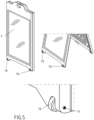
- Fig. 5 shows another embodiment of the frame stand, wherein some wheels 70, for example, two wheels 70 are provided at the bottom of one base frame 1 or base plate, for example, at the two feet of the frame 1. Owing to the wheels 70, it is much easier to move the folded frame stand from one place to another place.
- the wheel may be mounted by screws 71.
- Fig. 6a to Fig. 6d show some further embodiments of the frame stand, in order to enhance its stability in deployed status.
- a connecting rod 9 is installed between the two frames 1 and 2, at the bottom part of the frames.
- cover frame 12 surrounding a transparent plate Since the cover frame 12 surrounding a transparent plate is provided, inserted posters can be protected from water, dust and wind.
- the posters therein can be stretched over the surface of the cover frame in a taut position, and meanwhile be held in a substantially fixed position.
- the opening for inserting a poster is arranged at the upper side of the frame stand, so that the user only has to rotate the cover frame over a small angle, and a small opening is sufficient to remove and to insert a poster.
- the bottom edge of the cover frame is connected to the base plate, which forms a V-shape container.
- a user can finish the manipulation of changing posters in a very easy manner.
- One hand can handle the poster 4 and the other hand can handle the cover frame 12. There is no need for an of adhesive. The user has not to change his standing position.
- Fig. 2a and Fig. 2b explains how to insert a poster into the frame stand when the frame stand is in deployed status.
- the poster therein can also be changed when the frames are in folded flat status.
- various posters having various sizes can be spread on the base plate at one's disposal.
- the cover frame is closed, the poster therein is held in a substantially fixed position. Then, the frame stand is ready to be deployed for display.
- the stand frame according to our invention is preferred to have an inclined display surface when it is standing on the ground.
- the display surface generally has an acute angle relative to the ground.
- the gravity of the cover frame helps to close the cover frame and helps to keep the frame in a closed state.
- the gravity of the cover frame helps to press the poster to be in a tauter position.
- the weight of the cover frame can be burden by the base plate, which guarantees the stability and durability of the stand frame.
- the frame When a locking element is applied, the frame can be locked to a closed state.
- the manipulation is maintained to be simple.
- One hand unlocks the latch, and the other hand opens the cover frame.
- the two manipulations occur within a small distance and it is therefore easy to be finished at the same time.
- a detailed locking element is provided. It can be understood that many other locking element may be also applied. But the embodiment shown in Fig. 4 is specially easy in manipulation, simple in structure, and reliable in repeated use.
Landscapes
- Physics & Mathematics (AREA)
- General Physics & Mathematics (AREA)
- Engineering & Computer Science (AREA)
- Theoretical Computer Science (AREA)
- Mirrors, Picture Frames, Photograph Stands, And Related Fastening Devices (AREA)
Claims (12)
- Ein Rahmenständer für Plakate, umfassend einen Rahmen (1), der eine Grundplatte (11) umgibt, und einen Abdeckrahmen (12), wobei der Abdeckrahmen (12) eine Unterkante (122a) aufweist, die drehbar mit der Grundplatte (11) verbunden ist, wobei ein Verriegelungselement (61, 62, 65) eines Verriegelungsmechanismus an der Oberseite für den Abdeckrahmen (12) bereitgestellt ist, um den Abdeckrahmen (12) und die Grundplatte (11) miteinander zu verriegeln, dadurch gekennzeichnet, dass das Verriegelungselement (61, 62, 65) einen am Rahmen (1) angebrachten Riegel (61) umfasst, die einen Vorsprung (62) aufweist, der geeignet ist, in einen Schlitz (60) der Oberkante (122b) des Abdeckrahmens (12) eingesetzt zu werden, wobei der Verriegelungsmechanismus neben einem Griff des Rahmenständers angeordnet ist, wobei der Verriegelungsmechanismus eine vorgespannte Feder (66) umfasst, die den Verriegelungsmechanismus in seine verriegelte Position bewegen kann und den Verriegelungsmechanismus in seiner verriegelten Position halten kann.
- Der Rahmenständer gemäß einem der vorhergehenden Ansprüche, wobei eine Nut (30) in dem oberen Abschnitt der Grundplatte (11) vorgesehen ist und die Nut (30) so angeordnet ist, dass die Innenkante (123) der Oberkante (122b) des Abdeckrahmens (12) in die Nut (30) eingesetzt werden kann
- Der Rahmenständer gemäß einem der vorhergehenden Ansprüche, wobei das Verriegelungselement in der Lage ist, die Oberkante (122a) des Abdeckrahmens (12) mit der Grundplatte (11) zu verriegeln.
- Der Rahmenständer gemäß einem der vorhergehenden Ansprüche, wobei der Riegel (61) drehbar gelagert ist.
- Der Rahmenständer gemäß einem der vorhergehenden Ansprüche, wobei der Verriegelungsmechanismus eine Griffstange (65) umfasst, die an einem Riegel (61) angebracht und relativ zum Riegel nach vorne oder hinten gebogen ist und/oder wobei der Riegel und die Griffstange einen Winkel von vorzugsweise 90° bilden.
- Der Rahmenständer gemäß einem der vorhergehenden Ansprüche, wobei ein Loch (5) am Oberteil (3) der Grundplatte (11) zum Bilden eines Griffs für den Rahmenständer und zum Ermöglichen, dass die Hand (68) eines Benutzers durch das Loch (5) hindurchgeht, um den Riegel (61) anzuheben, vorgesehen ist.
- Der Rahmenständer gemäß dem vorhergehenden Anspruch, wobei die Grundplatte (1) eine Nut (67) an der Rückseite neben dem Loch (5) umfasst und wobei das Verriegelungselement (61, 62, 65) des Verriegelungsmechanismus in der Nut (67) angeordnet ist.
- Der Rahmenständer gemäß einem der vorhergehenden Ansprüche, dadurch gekennzeichnet, dass die Grundplatte einen umlaufenden Vorsprung (125) umfasst, der den Abdeckrahmen (12) umgibt, wenn sich der Abdeckrahmen (12) in seiner geschlossenen Position befindet.
- Der Rahmenständer gemäß einem der vorhergehenden Ansprüche, dadurch gekennzeichnet, dass der Abdeckrahmen (12) eine transparente Platte (121) umgibt.
- Der Rahmenständer gemäß einem der vorhergehenden Ansprüche, wobei die Grundplatte (11) eine geneigte Anzeigefläche aufweist, wenn der Rahmenständer in der vorgesehenen Weise auf einem Boden steht.
- Der Rahmenständer gemäß einem der vorhergehenden Ansprüche, wobei der Rahmenständer ein A- oder ein V-förmiger Rahmenständer ist, wobei der Rahmenständer eine zweite Grundplatte oder einen Grundrahmen umfasst.
- Der Rahmenständer nach dem vorhergehendem Anspruch, wobei die erste Grundplatte und die zweite Grundplatte bzw. die erste Grundplatte und der Grundrahmen durch ein Scharnier miteinander verbunden sind.
Priority Applications (2)
| Application Number | Priority Date | Filing Date | Title |
|---|---|---|---|
| PL17704233.0T PL3580743T3 (pl) | 2017-02-08 | 2017-02-08 | Stojak ramkowy na plakaty |
| HUE17704233A HUE071141T2 (hu) | 2017-02-08 | 2017-02-08 | Keretes állvány plakátokhoz |
Applications Claiming Priority (1)
| Application Number | Priority Date | Filing Date | Title |
|---|---|---|---|
| PCT/EP2017/052765 WO2018145741A1 (en) | 2017-02-08 | 2017-02-08 | A frame stand for posters |
Publications (3)
| Publication Number | Publication Date |
|---|---|
| EP3580743A1 EP3580743A1 (de) | 2019-12-18 |
| EP3580743B1 true EP3580743B1 (de) | 2025-04-02 |
| EP3580743C0 EP3580743C0 (de) | 2025-04-02 |
Family
ID=58009823
Family Applications (1)
| Application Number | Title | Priority Date | Filing Date |
|---|---|---|---|
| EP17704233.0A Active EP3580743B1 (de) | 2017-02-08 | 2017-02-08 | Rahmenständer für poster |
Country Status (6)
| Country | Link |
|---|---|
| US (1) | US10832601B2 (de) |
| EP (1) | EP3580743B1 (de) |
| ES (1) | ES3024657T3 (de) |
| HU (1) | HUE071141T2 (de) |
| PL (1) | PL3580743T3 (de) |
| WO (1) | WO2018145741A1 (de) |
Families Citing this family (8)
| Publication number | Priority date | Publication date | Assignee | Title |
|---|---|---|---|---|
| WO2020163135A1 (en) * | 2019-02-04 | 2020-08-13 | SmartSign LLC | A-frame sign support |
| CN110288928B (zh) * | 2019-08-13 | 2021-11-05 | 上海升煊医药科技有限公司 | 一种基于铰接传动的可折叠广告支架 |
| US11605317B2 (en) * | 2020-03-27 | 2023-03-14 | American Louver Company | Portable sign frame |
| US11688311B2 (en) | 2021-02-05 | 2023-06-27 | Timessquarednyc Corp | Y-frame digital signage system |
| US12431044B2 (en) | 2021-02-17 | 2025-09-30 | M.T Reklam Anonim Sirketi | Poster display device and manufacturing method |
| US11779119B1 (en) * | 2021-05-25 | 2023-10-10 | Beth Metsch Goldman | Folding chair with user interchangeable frame and coat rack adapted for hanging on a wall |
| JP2023167638A (ja) * | 2022-05-12 | 2023-11-24 | アラオ株式会社 | シート状物の保持板 |
| USD1085619S1 (en) * | 2022-08-24 | 2025-07-22 | Tawanna D. Tyler | Dolly |
Citations (8)
| Publication number | Priority date | Publication date | Assignee | Title |
|---|---|---|---|---|
| US1487500A (en) * | 1923-01-11 | 1924-03-18 | Clifford Allday | Changeable sign with locking device |
| US2073403A (en) * | 1935-11-23 | 1937-03-09 | Abraham G Goldberg | Display device |
| US2454648A (en) * | 1946-06-11 | 1948-11-23 | City Tank Corp | Sign stand for displaying posters |
| FR2417153A1 (en) * | 1978-02-09 | 1979-09-07 | World Acrilux | Publicity display support panel - consists of transparent window and back plate hinged together at turned-over edges |
| US4337590A (en) * | 1980-09-18 | 1982-07-06 | Harold Jackson | Reflective device for carrying variable information for example for advertising purposes |
| US4949483A (en) * | 1988-11-14 | 1990-08-21 | William R. Dobson | Adjustable thickness display frame |
| DE20315284U1 (de) * | 2003-10-04 | 2003-12-11 | Hans Dragon & Co. Werbemittel Gmbh | Aufstelltafel bzw. A-Ständer mit Klapptasche(n) für Plakate und/oder insbesondere Presseprodukte (Zeitungen, Zeitschriften usw.) |
| US20060032098A1 (en) * | 2004-08-13 | 2006-02-16 | Glass Geoffrey M | Portable sign frame assembly with changeable signage |
Family Cites Families (5)
| Publication number | Priority date | Publication date | Assignee | Title |
|---|---|---|---|---|
| US1573264A (en) * | 1924-03-15 | 1926-02-16 | Harry A Mankameyer | Self-closing case |
| US2075401A (en) | 1935-06-15 | 1937-03-30 | American Machine & Metals Inc | Display stand |
| US6131320A (en) * | 1997-10-14 | 2000-10-17 | American Allsafe Company | Floor sign |
| US6615523B1 (en) | 1999-12-06 | 2003-09-09 | Adrian Curbelo | Reversible A-frame sign |
| US20110239506A1 (en) | 2010-04-06 | 2011-10-06 | Glass Jr Geoffrey M | Sign frame |
-
2017
- 2017-02-08 WO PCT/EP2017/052765 patent/WO2018145741A1/en not_active Ceased
- 2017-02-08 ES ES17704233T patent/ES3024657T3/es active Active
- 2017-02-08 US US16/480,883 patent/US10832601B2/en active Active
- 2017-02-08 EP EP17704233.0A patent/EP3580743B1/de active Active
- 2017-02-08 PL PL17704233.0T patent/PL3580743T3/pl unknown
- 2017-02-08 HU HUE17704233A patent/HUE071141T2/hu unknown
Patent Citations (9)
| Publication number | Priority date | Publication date | Assignee | Title |
|---|---|---|---|---|
| US1487500A (en) * | 1923-01-11 | 1924-03-18 | Clifford Allday | Changeable sign with locking device |
| US2073403A (en) * | 1935-11-23 | 1937-03-09 | Abraham G Goldberg | Display device |
| US2454648A (en) * | 1946-06-11 | 1948-11-23 | City Tank Corp | Sign stand for displaying posters |
| FR2417153A1 (en) * | 1978-02-09 | 1979-09-07 | World Acrilux | Publicity display support panel - consists of transparent window and back plate hinged together at turned-over edges |
| US4337590A (en) * | 1980-09-18 | 1982-07-06 | Harold Jackson | Reflective device for carrying variable information for example for advertising purposes |
| US4949483A (en) * | 1988-11-14 | 1990-08-21 | William R. Dobson | Adjustable thickness display frame |
| DE20315284U1 (de) * | 2003-10-04 | 2003-12-11 | Hans Dragon & Co. Werbemittel Gmbh | Aufstelltafel bzw. A-Ständer mit Klapptasche(n) für Plakate und/oder insbesondere Presseprodukte (Zeitungen, Zeitschriften usw.) |
| US20060032098A1 (en) * | 2004-08-13 | 2006-02-16 | Glass Geoffrey M | Portable sign frame assembly with changeable signage |
| US7337569B2 (en) * | 2004-08-13 | 2008-03-04 | American Louver Company | Portable sign frame assembly with changeable signage |
Also Published As
| Publication number | Publication date |
|---|---|
| ES3024657T3 (en) | 2025-06-05 |
| HUE071141T2 (hu) | 2025-08-28 |
| US10832601B2 (en) | 2020-11-10 |
| EP3580743A1 (de) | 2019-12-18 |
| US20190392738A1 (en) | 2019-12-26 |
| PL3580743T3 (pl) | 2025-07-21 |
| WO2018145741A1 (en) | 2018-08-16 |
| EP3580743C0 (de) | 2025-04-02 |
Similar Documents
| Publication | Publication Date | Title |
|---|---|---|
| EP3580743B1 (de) | Rahmenständer für poster | |
| US7380563B2 (en) | Collapsible canopy having wheels | |
| US7748151B2 (en) | Stabilized A-frame sign stand | |
| US5215379A (en) | Information storage envelope | |
| US5752736A (en) | Collapsible truck bed cover | |
| US5464115A (en) | Molded plastic footlocker | |
| US6349426B1 (en) | Portable outdoor toilet with advertising indicia | |
| JPH08511632A (ja) | ポスター及び表示看板組立体 | |
| KR101997586B1 (ko) | 현수막 게시대 | |
| US4411085A (en) | Slit-tube sign stand | |
| US6082570A (en) | Foldable box assembly | |
| US20070138368A1 (en) | Stabilized a-frame sign stand | |
| US20050108911A1 (en) | Flip-open floor sign | |
| US4756108A (en) | Display frame | |
| WO1993014484A1 (en) | Portable sign | |
| US20100133401A1 (en) | Flexible support apparatus | |
| CA2551353A1 (en) | Folding shelf unit for a locker | |
| US8033041B2 (en) | Display panel tensioner and assemblies thereof | |
| AU2011100546A4 (en) | Improvements to portable signs | |
| US9303373B1 (en) | Collapsible pylon | |
| CA2597968A1 (en) | Case for holding signs | |
| JPH1074057A (ja) | 折畳み収納型移動標示板 | |
| EP2131344B1 (de) | Staffeleiförmiges zweiseitiges Baustellen- und Warnsignal mit verbesserter Bündelung | |
| AU667501B2 (en) | Portable sign | |
| KR200352348Y1 (ko) | 절첩식 안내 표시구 |
Legal Events
| Date | Code | Title | Description |
|---|---|---|---|
| STAA | Information on the status of an ep patent application or granted ep patent |
Free format text: STATUS: UNKNOWN |
|
| STAA | Information on the status of an ep patent application or granted ep patent |
Free format text: STATUS: THE INTERNATIONAL PUBLICATION HAS BEEN MADE |
|
| PUAI | Public reference made under article 153(3) epc to a published international application that has entered the european phase |
Free format text: ORIGINAL CODE: 0009012 |
|
| STAA | Information on the status of an ep patent application or granted ep patent |
Free format text: STATUS: REQUEST FOR EXAMINATION WAS MADE |
|
| 17P | Request for examination filed |
Effective date: 20190703 |
|
| AK | Designated contracting states |
Kind code of ref document: A1 Designated state(s): AL AT BE BG CH CY CZ DE DK EE ES FI FR GB GR HR HU IE IS IT LI LT LU LV MC MK MT NL NO PL PT RO RS SE SI SK SM TR |
|
| AX | Request for extension of the european patent |
Extension state: BA ME |
|
| DAV | Request for validation of the european patent (deleted) | ||
| DAX | Request for extension of the european patent (deleted) | ||
| STAA | Information on the status of an ep patent application or granted ep patent |
Free format text: STATUS: EXAMINATION IS IN PROGRESS |
|
| 17Q | First examination report despatched |
Effective date: 20210512 |
|
| GRAP | Despatch of communication of intention to grant a patent |
Free format text: ORIGINAL CODE: EPIDOSNIGR1 |
|
| STAA | Information on the status of an ep patent application or granted ep patent |
Free format text: STATUS: GRANT OF PATENT IS INTENDED |
|
| INTG | Intention to grant announced |
Effective date: 20241021 |
|
| GRAS | Grant fee paid |
Free format text: ORIGINAL CODE: EPIDOSNIGR3 |
|
| GRAA | (expected) grant |
Free format text: ORIGINAL CODE: 0009210 |
|
| STAA | Information on the status of an ep patent application or granted ep patent |
Free format text: STATUS: THE PATENT HAS BEEN GRANTED |
|
| AK | Designated contracting states |
Kind code of ref document: B1 Designated state(s): AL AT BE BG CH CY CZ DE DK EE ES FI FR GB GR HR HU IE IS IT LI LT LU LV MC MK MT NL NO PL PT RO RS SE SI SK SM TR |
|
| REG | Reference to a national code |
Ref country code: GB Ref legal event code: FG4D |
|
| REG | Reference to a national code |
Ref country code: CH Ref legal event code: EP |
|
| REG | Reference to a national code |
Ref country code: IE Ref legal event code: FG4D |
|
| U01 | Request for unitary effect filed |
Effective date: 20250402 |
|
| U07 | Unitary effect registered |
Designated state(s): AT BE BG DE DK EE FI FR IT LT LU LV MT NL PT RO SE SI Effective date: 20250408 |
|
| REG | Reference to a national code |
Ref country code: ES Ref legal event code: FG2A Ref document number: 3024657 Country of ref document: ES Kind code of ref document: T3 Effective date: 20250605 |
|
| REG | Reference to a national code |
Ref country code: HU Ref legal event code: AG4A Ref document number: E071141 Country of ref document: HU |
|
| PG25 | Lapsed in a contracting state [announced via postgrant information from national office to epo] |
Ref country code: GR Free format text: LAPSE BECAUSE OF FAILURE TO SUBMIT A TRANSLATION OF THE DESCRIPTION OR TO PAY THE FEE WITHIN THE PRESCRIBED TIME-LIMIT Effective date: 20250703 Ref country code: NO Free format text: LAPSE BECAUSE OF FAILURE TO SUBMIT A TRANSLATION OF THE DESCRIPTION OR TO PAY THE FEE WITHIN THE PRESCRIBED TIME-LIMIT Effective date: 20250702 |
|
| PG25 | Lapsed in a contracting state [announced via postgrant information from national office to epo] |
Ref country code: HR Free format text: LAPSE BECAUSE OF FAILURE TO SUBMIT A TRANSLATION OF THE DESCRIPTION OR TO PAY THE FEE WITHIN THE PRESCRIBED TIME-LIMIT Effective date: 20250402 |
|
| PG25 | Lapsed in a contracting state [announced via postgrant information from national office to epo] |
Ref country code: RS Free format text: LAPSE BECAUSE OF FAILURE TO SUBMIT A TRANSLATION OF THE DESCRIPTION OR TO PAY THE FEE WITHIN THE PRESCRIBED TIME-LIMIT Effective date: 20250702 |
|
| PG25 | Lapsed in a contracting state [announced via postgrant information from national office to epo] |
Ref country code: IS Free format text: LAPSE BECAUSE OF FAILURE TO SUBMIT A TRANSLATION OF THE DESCRIPTION OR TO PAY THE FEE WITHIN THE PRESCRIBED TIME-LIMIT Effective date: 20250802 |