EP3580032B1 - Internally hollow body, mold and method thereof - Google Patents
Internally hollow body, mold and method thereof Download PDFInfo
- Publication number
- EP3580032B1 EP3580032B1 EP18709080.8A EP18709080A EP3580032B1 EP 3580032 B1 EP3580032 B1 EP 3580032B1 EP 18709080 A EP18709080 A EP 18709080A EP 3580032 B1 EP3580032 B1 EP 3580032B1
- Authority
- EP
- European Patent Office
- Prior art keywords
- punch
- impression
- die
- mold
- main
- Prior art date
- Legal status (The legal status is an assumption and is not a legal conclusion. Google has not performed a legal analysis and makes no representation as to the accuracy of the status listed.)
- Active
Links
Images


Classifications
-
- B—PERFORMING OPERATIONS; TRANSPORTING
- B29—WORKING OF PLASTICS; WORKING OF SUBSTANCES IN A PLASTIC STATE IN GENERAL
- B29C—SHAPING OR JOINING OF PLASTICS; SHAPING OF MATERIAL IN A PLASTIC STATE, NOT OTHERWISE PROVIDED FOR; AFTER-TREATMENT OF THE SHAPED PRODUCTS, e.g. REPAIRING
- B29C45/00—Injection moulding, i.e. forcing the required volume of moulding material through a nozzle into a closed mould; Apparatus therefor
- B29C45/17—Component parts, details or accessories; Auxiliary operations
- B29C45/26—Moulds
-
- B—PERFORMING OPERATIONS; TRANSPORTING
- B29—WORKING OF PLASTICS; WORKING OF SUBSTANCES IN A PLASTIC STATE IN GENERAL
- B29C—SHAPING OR JOINING OF PLASTICS; SHAPING OF MATERIAL IN A PLASTIC STATE, NOT OTHERWISE PROVIDED FOR; AFTER-TREATMENT OF THE SHAPED PRODUCTS, e.g. REPAIRING
- B29C45/00—Injection moulding, i.e. forcing the required volume of moulding material through a nozzle into a closed mould; Apparatus therefor
- B29C45/0053—Injection moulding, i.e. forcing the required volume of moulding material through a nozzle into a closed mould; Apparatus therefor combined with a final operation, e.g. shaping
- B29C45/006—Joining parts moulded in separate cavities
- B29C45/0062—Joined by injection moulding
-
- B—PERFORMING OPERATIONS; TRANSPORTING
- B29—WORKING OF PLASTICS; WORKING OF SUBSTANCES IN A PLASTIC STATE IN GENERAL
- B29C—SHAPING OR JOINING OF PLASTICS; SHAPING OF MATERIAL IN A PLASTIC STATE, NOT OTHERWISE PROVIDED FOR; AFTER-TREATMENT OF THE SHAPED PRODUCTS, e.g. REPAIRING
- B29C45/00—Injection moulding, i.e. forcing the required volume of moulding material through a nozzle into a closed mould; Apparatus therefor
- B29C45/14—Injection moulding, i.e. forcing the required volume of moulding material through a nozzle into a closed mould; Apparatus therefor incorporating preformed parts or layers, e.g. injection moulding around inserts or for coating articles
- B29C45/14467—Joining articles or parts of a single article
-
- B—PERFORMING OPERATIONS; TRANSPORTING
- B29—WORKING OF PLASTICS; WORKING OF SUBSTANCES IN A PLASTIC STATE IN GENERAL
- B29C—SHAPING OR JOINING OF PLASTICS; SHAPING OF MATERIAL IN A PLASTIC STATE, NOT OTHERWISE PROVIDED FOR; AFTER-TREATMENT OF THE SHAPED PRODUCTS, e.g. REPAIRING
- B29C45/00—Injection moulding, i.e. forcing the required volume of moulding material through a nozzle into a closed mould; Apparatus therefor
- B29C45/16—Making multilayered or multicoloured articles
- B29C45/1615—The materials being injected at different moulding stations
- B29C45/162—The materials being injected at different moulding stations using means, e.g. mould parts, for transferring an injected part between moulding stations
-
- B—PERFORMING OPERATIONS; TRANSPORTING
- B65—CONVEYING; PACKING; STORING; HANDLING THIN OR FILAMENTARY MATERIAL
- B65D—CONTAINERS FOR STORAGE OR TRANSPORT OF ARTICLES OR MATERIALS, e.g. BAGS, BARRELS, BOTTLES, BOXES, CANS, CARTONS, CRATES, DRUMS, JARS, TANKS, HOPPERS, FORWARDING CONTAINERS; ACCESSORIES, CLOSURES, OR FITTINGS THEREFOR; PACKAGING ELEMENTS; PACKAGES
- B65D11/00—Containers having bodies formed by interconnecting or uniting two or more rigid, or substantially rigid, components made wholly or mainly of plastics material
- B65D11/10—Containers having bodies formed by interconnecting or uniting two or more rigid, or substantially rigid, components made wholly or mainly of plastics material of polygonal cross-section and all parts being permanently connected to each other
-
- B—PERFORMING OPERATIONS; TRANSPORTING
- B65—CONVEYING; PACKING; STORING; HANDLING THIN OR FILAMENTARY MATERIAL
- B65D—CONTAINERS FOR STORAGE OR TRANSPORT OF ARTICLES OR MATERIALS, e.g. BAGS, BARRELS, BOTTLES, BOXES, CANS, CARTONS, CRATES, DRUMS, JARS, TANKS, HOPPERS, FORWARDING CONTAINERS; ACCESSORIES, CLOSURES, OR FITTINGS THEREFOR; PACKAGING ELEMENTS; PACKAGES
- B65D21/00—Nestable, stackable or joinable containers; Containers of variable capacity
- B65D21/02—Containers specially shaped, or provided with fittings or attachments, to facilitate nesting, stacking, or joining together
- B65D21/0209—Containers specially shaped, or provided with fittings or attachments, to facilitate nesting, stacking, or joining together stackable or joined together one-upon-the-other in the upright or upside-down position
- B65D21/023—Closed containers provided with local cooperating elements in the top and bottom surfaces, e.g. projection and recess
- B65D21/0231—Bottles, canisters or jars whereby the neck or handle project into a cooperating cavity in the bottom
-
- B—PERFORMING OPERATIONS; TRANSPORTING
- B29—WORKING OF PLASTICS; WORKING OF SUBSTANCES IN A PLASTIC STATE IN GENERAL
- B29C—SHAPING OR JOINING OF PLASTICS; SHAPING OF MATERIAL IN A PLASTIC STATE, NOT OTHERWISE PROVIDED FOR; AFTER-TREATMENT OF THE SHAPED PRODUCTS, e.g. REPAIRING
- B29C45/00—Injection moulding, i.e. forcing the required volume of moulding material through a nozzle into a closed mould; Apparatus therefor
- B29C45/17—Component parts, details or accessories; Auxiliary operations
- B29C45/26—Moulds
- B29C2045/2683—Plurality of independent mould cavities in a single mould
-
- B—PERFORMING OPERATIONS; TRANSPORTING
- B29—WORKING OF PLASTICS; WORKING OF SUBSTANCES IN A PLASTIC STATE IN GENERAL
- B29C—SHAPING OR JOINING OF PLASTICS; SHAPING OF MATERIAL IN A PLASTIC STATE, NOT OTHERWISE PROVIDED FOR; AFTER-TREATMENT OF THE SHAPED PRODUCTS, e.g. REPAIRING
- B29C66/00—General aspects of processes or apparatus for joining preformed parts
- B29C66/01—General aspects dealing with the joint area or with the area to be joined
- B29C66/05—Particular design of joint configurations
- B29C66/20—Particular design of joint configurations particular design of the joint lines, e.g. of the weld lines
- B29C66/24—Particular design of joint configurations particular design of the joint lines, e.g. of the weld lines said joint lines being closed or non-straight
- B29C66/242—Particular design of joint configurations particular design of the joint lines, e.g. of the weld lines said joint lines being closed or non-straight said joint lines being closed, i.e. forming closed contours
- B29C66/2424—Particular design of joint configurations particular design of the joint lines, e.g. of the weld lines said joint lines being closed or non-straight said joint lines being closed, i.e. forming closed contours being a closed polygonal chain
- B29C66/24243—Particular design of joint configurations particular design of the joint lines, e.g. of the weld lines said joint lines being closed or non-straight said joint lines being closed, i.e. forming closed contours being a closed polygonal chain forming a quadrilateral
- B29C66/24244—Particular design of joint configurations particular design of the joint lines, e.g. of the weld lines said joint lines being closed or non-straight said joint lines being closed, i.e. forming closed contours being a closed polygonal chain forming a quadrilateral forming a rectangle
-
- B—PERFORMING OPERATIONS; TRANSPORTING
- B29—WORKING OF PLASTICS; WORKING OF SUBSTANCES IN A PLASTIC STATE IN GENERAL
- B29C—SHAPING OR JOINING OF PLASTICS; SHAPING OF MATERIAL IN A PLASTIC STATE, NOT OTHERWISE PROVIDED FOR; AFTER-TREATMENT OF THE SHAPED PRODUCTS, e.g. REPAIRING
- B29C66/00—General aspects of processes or apparatus for joining preformed parts
- B29C66/50—General aspects of joining tubular articles; General aspects of joining long products, i.e. bars or profiled elements; General aspects of joining single elements to tubular articles, hollow articles or bars; General aspects of joining several hollow-preforms to form hollow or tubular articles
- B29C66/51—Joining tubular articles, profiled elements or bars; Joining single elements to tubular articles, hollow articles or bars; Joining several hollow-preforms to form hollow or tubular articles
- B29C66/54—Joining several hollow-preforms, e.g. half-shells, to form hollow articles, e.g. for making balls, containers; Joining several hollow-preforms, e.g. half-cylinders, to form tubular articles
- B29C66/542—Joining several hollow-preforms, e.g. half-shells, to form hollow articles, e.g. for making balls, containers; Joining several hollow-preforms, e.g. half-cylinders, to form tubular articles joining hollow covers or hollow bottoms to open ends of container bodies
-
- B—PERFORMING OPERATIONS; TRANSPORTING
- B29—WORKING OF PLASTICS; WORKING OF SUBSTANCES IN A PLASTIC STATE IN GENERAL
- B29L—INDEXING SCHEME ASSOCIATED WITH SUBCLASS B29C, RELATING TO PARTICULAR ARTICLES
- B29L2031/00—Other particular articles
- B29L2031/712—Containers; Packaging elements or accessories, Packages
- B29L2031/7172—Fuel tanks, jerry cans
Definitions
- the present invention relates to the production of internally hollow bodies.
- the invention relates to a particular type of internally hollow body made of plastic, such as for example a container, the manufacturing method thereof and the related mold adapted to be used during the manufacturing method.
- Plastic hollow containers made by means of rotational molding or blow molding techniques, designed to contain a plurality of liquid, solid or gaseous substances belonging to many sectors of industry (food, chemical, pharmaceutical, etc.) are known in the art.
- included in this type of containers are those designed to contain substances that must not escape uncontrollably and which therefore must be provided with closure systems (screw caps, pressure covers, valves, etc.)
- the internally hollow bodies of the prior art produced using traditional molding techniques such as bottles, barrels, jerrycans, flasks, bins, tanks, small cisterns have the disadvantage of being difficult to make in square shapes, for example box-shaped or approximable to those of a parallelepiped with slightly rounded edges.
- blow molding does not allow the production of details with constant thickness and, consequently, products made with such technology have areas that require a greater amount of plastic material for producing the container, with a consequent greater demand for resources (financial and material). Furthermore, blow-molding technology and, in particular, rotational molding technology are less productive than other technologies, such as injection molding.
- One of the objects of the present invention is to improve the robustness of hollow bodies made of plastic, made by molding two half-shells (a main body and a closure body) joined together.
- a further object of the present invention is to improve the efficiency and effectiveness of production of such internally hollow bodies.
- an internally hollow plastic body having an inner cavity 2, preferably adapted to contain liquid, solid or gaseous material is collectively indicated at 1.
- the term “internally” means that the cavity 2 of the hollow body is internal to the body, which is to say that, for example, the body has an inner surface that defines, at least partially, such cavity and that is in contact with a liquid, solid or gaseous material that flows, or is contained, at least partially, in the cavity, and an outer surface of the hollow body that instead is in contact with the external environment or, for example, with a different or other element with respect to the one contained, or that flows, in the cavity.
- This type of internally hollow bodies includes, for example conduits, channels, pipes or container bodies.
- the internally hollow body 1 comprises a main body 4 shaped so as to comprise side walls 6, having an inner surface 8 which at least partially defines said cavity 2 and which ends with a shaped edge 10 which delimits an engagement opening 12 to the cavity 2.
- the internally hollow body 1 further comprises a closure body 14, comprising side closure walls 16 having an inner sealing surface 18. Such inner sealing surface 18 is engaged at least partially with the inner surface 8 of the side walls 6 of the main body 4, and the closure body 14 at least partially closes the cavity 2 at the engagement opening 12.
- such closure body 14 is the bottom of a container, as in the embodiment shown in figure 1 and figure 1a , or the cover, as in the embodiment shown in the document WO2016092407 , or one of the two half-shapes that, when joined, form the entire internally hollow body, or simply a portion of the internally hollow body or an ancillary portion (for example a handle of a container, an inlet mouth and the like).
- the internally hollow body 1 comprises a joining element 20, also made of plastic, having the function of securely joining the main body 4 and the closure body 14.
- the plastic material with which the joining element 20 is made is adapted to fuse and weld with the plastic material with which the main body 4 or the closure body 14 is made.
- the joining element is made of the same plastic material as the main body 4 and/or the closure body 14 or with a different plastic but one adapted to fuse with the plastic of the closure body 14 and/or of the main body 4.
- plastic material or plastic means a polymer, for example a synthetic resin, or an elastomer, or a thermoplastic or thermosetting polymer preferably selected from the group of polyethylenes, polypropylenes, methacrylates, polycarbonates or polyamides.
- the main body 4 is joined to the closure body 14 at least partially along the shaped edge 10 by means of said joining element 20 or preferably along the entire shaped edge 10.
- the overmolding of the joining element 20 on the closure body 14 and on the main body 4 occurs by injection molding, for example through a step of injection molding of a synthetic resin melted in the overmolding seat 22, when the closure body 14 and the main body 4 are mutually engaged and inserted in a mold 500 for overmolding the joining element 20.
- the closure body 14 is adapted to close completely and sealingly the cavity 2, at the engagement opening 12.
- hollow containers are created able to contain, for example, liquid, solid or gaseous substances, such as vials, barrels, jerrycans, flasks, bins, tanks, floats, buoys, lifebuoys, fenders, small cisterns, or bottles, wherein the closure body 14 is preferably the bottom or the cover of such containers.
- the closure body 14 and the main body 4 respectively represent each of the two half-shells (preferably equal to each other) to be joined by the joining element to form the buoy, float, lifebuoy or fender.
- the closure body 14 has, moreover, a mold engagement cavity 30 in which a mold 500 for injection molding or a part thereof is adapted to counteract the pressure generated in the overmolding seat 22 by injection means during an overmolding step of the joining element 20 and is at least partially couplable by shape-coupling.
- This mold engagement cavity 30 is preferably formed externally of the cavity 2 of the hollow body 1, i.e. it is at least partially delimited from the outer surface of the closure body opposite the inner surface facing the cavity 2 of the hollow body 1.
- the mold engagement cavity 30 is arranged on the opposite side with respect to the inner cavity 2 of the hollow body and is defined at least in part (or totally) by the outer surface adapted to be in contact with the external environment or in any case with a different element than that which is contained or flows into the cavity 2 (i.e. the mold engagement cavity 30 does not face into the cavity 2).
- such mold engagement cavity 30 is delimited by the outer closure surface 17 of the side closure walls 16 of the closure body, opposite the inner sealing surface 18 towards the mold engagement cavity 30. In this way, one avoids that, during the overmolding step, the injection of the resin forming the joining element 20, causes a disengagement between the inner sealing surface 18 of the closure body 14 and the inner surface 8 of the side walls 6 the main body 4.
- the outer closure surface 17 that defines the mold engagement cavity 30 faces the opposite side with respect to the cavity 2. It follows that the mold 500 engages the mold engagement cavity 30 externally with respect to the cavity 2 of the hollow body 1 obtained at the end of the molding step. In this way, the molding steps are reduced, and it is also possible to produce totally closed hollow bodies 1.
- the mold engagement cavity 30 were formed in the cavity part 2 of the hollow body 1, in the case of totally closed hollow bodies, the mold portion inside the mold cavity 30 and the cavity 2 would not allow the total closure of the hollow body 1. In effect, in this latter case, it would be necessary to leave an access to the cavity 2 free for removing the overmolding mold 500 (or part of it, for example, the die or the punch).
- the inner sealing surface 18 of the closure body 14 is engaged at least partially in abutment with the inner surface 8 of the main body 4 along the engagement portion 8' of such inner surface 8 in such a way as to counteract a mechanical stress between the closure body 14 and the main body 4 along a preferential direction X' (for example a main vertical direction of extension of the hollow body) and in the direction of insertion of the closure body 14 in the inner cavity 2.
- a preferential direction X' for example a main vertical direction of extension of the hollow body
- the engagement between the inner sealing surface 18 and the inner surface of the main body 4 allows any compressive stress between the closure body 14 and the main body 4 to be distributed along the side walls 6 of the main body. This advantageously allows any impulsive loads acting between the main body 4 and the closure body 14, for example, the hollow body accidental falling, to be supported.
- the mechanical stress along the preferential direction X', due to the jerrycan accidently falling with impact on the closure body 14, would be directly distributed by the closure body 14 to the side walls 6 of the main body 4, ensuring greater impact strength.
- the engagement portion 8' is an engagement surface inclined with respect to the preferential direction X', even more preferably perpendicular to the preferential direction X'.
- the engagement portion 8' is the rise of a step 81 formed on the side walls 6 of the main body 4.
- the inner sealing surface 18 of the closure body 14 comprises an abutment portion 18', inclined (preferably perpendicular) with respect to the preferential direction X' and sealingly resting on the engagement portion 8' of the main body 4.
- This allows both a sealed joint to be obtained between the closure body 14 and the main body 4 (particularly advantageous in the case of hollow bodies of solid, liquid or gaseous substances) and any mechanical stress to be distributed along an extended contact surface.
- the joining element 20 is contained along its sides between the side walls 6 of the main body and the side closure walls 16. In this way, the joining element remains hidden from the view of an observer looking at the hollow body along a direction perpendicular to the side walls. Moreover, preferably, having defined a transverse plane P perpendicular to the preferential direction X' (for example perpendicular to the side walls 6), the joining element 20 is in contact with the external environment only along an outer surface 201, having at least a virtual tangent plane V parallel to said transverse plane P.
- the joining element 20 is preferably in contact with the outside only along a surface thereof facing outwards on the opposite side of the bottom of the container or the jerrycan (for example as shown in figures 2a to 2f ).
- the outer surface 201 of the joining element is in contact with the outside in a discontinuous manner, i.e. only in regions spaced from one another, as shown for example in figure 2a .
- the joining element is totally contained between the side walls 6 of the main body and the side closure walls 16 of the main body, except at such regions spaced apart from one another in contact with the external environment.
- these spaced regions of the outer surface 21 are preferably located at the entry points of the resin during the overmolding step of the joining element 20 inside the mold 500.
- the joining element 20 is in contact with the external environment only along its outer surface 201, flat and parallel to said transverse plane P.
- guide ribs 140 are preferably formed on the closure body 14, adapted to guide the closure body 14 during the step of coupling with the main body 4 towards the inner cavity 2.
- the guide ribs are spaced from one another and protrude from the main body 14 towards the inner cavity 2.
- the guide ribs 140 comprise an inclined surface 141 adapted to slide along an edge of the side walls 6 of the main body during the coupling step.
- Such inclined surface 141 is, for example, connected to the abutment portion 18', so as to facilitate the engagement of the closure body 14 during the insertion step in the main body 4 until it abuts the abutment portion 18' with the engagement portion 8' of the main body 4.
- the internally hollow body 1 described up to now may be obtained by means of the mold 500 and through a production method according to the continuation of the present description.
- Mold 500 means a mold for injection molding, for example formed of two or more half-molds, for example a punch 50' and a die 50'', each bearing an impression designed to engage according to shape-coupling with the main body 4 or with the closure body 14.
- the main body 4 is inserted in the die 50" of the overmolding mold 500 according to shape-coupling and the closure body 14 is inserted into the punch 50' of the mold 500 according to shape-coupling.
- a part of the walls forming the punch and/or a part of the walls forming the die are adapted to counteract the pressure generated on the overmolding seat 22 by the injection means during an overmolding step of the joining element 20.
- a die wall or only a punch wall 50a (and not both at the same time) is in contact with the synthetic resin during the overmolding step of the joining element, and, in addition to counteracting the pressure during the step of injecting the synthetic resin, such die or punch wall 50a defines an outer closure wall of the overmolding seat of the joining element.
- the outer surface portion 201 of the joining element 20 is formed. In this way, the joining element 20 is contained along its sides between the side walls 6 of the main body and the side closure walls 16, avoiding making the structure of the mold 500 complex.
- the mold engagement cavity 30 comprises an abutment surface 50 adapted to receive in abutment a portion of the mold and side walls forming the outer closure surface 17 on which the mold walls 51 are at least partially engaged to counteract the pressure generated by the injection means during the overmolding step of the joining element 20.
- the mold engagement cavity 30 has an annular shape with a "U" cross-section.
- the joining element 20 completely fills the overmolding seat 22, so as to allow stable welding between the main body 4 and the closure body 14.
- the overmolding seat 22 (and therefore the joining element 20, once molded), is delimited both on the top and on the side by the inner surface 8 of the side walls 6 of the main body 4 and, on the side facing the inner cavity 2, by the side closure walls 16.
- the joining element 20 annularly wraps the hollow body 1, creating a sealing welded ring between the main body 4 and the closure body 14.
- closure body 14 or the main body 4 also acts as the bottom of a container
- main body 4 or the closure body 14 comprises a bottom wall, preferably integral with the side closure walls 16, having an upper bottom surface 15a, which faces the cavity 2 of the container and which constitutes the inner bottom surface of the container.
- the bottom wall 15 further comprises an outer bottom surface 15b, opposite the upper bottom surface 15a, not communicating with the cavity 2, but facing the outside of the container.
- the internally hollow body 1 comprises at least one reinforcing wall 300, arranged transversely between two walls 17a, 17b facing each other and defining the mold engagement cavity 30.
- the method for producing the plastic, internally hollow body provides for joining the main body 4 and the closure body 14 in the same step wherein occurs the molding of a second closure body 14' and/or of a second main body to be used in a subsequent union step to obtain a second internally hollow body.
- an internally hollow body 1 is defined in independent claim 3.
- the main body 4 shaped in plastic and the closure body 14 are made by injection molding.
- the mold 500 is inserted at least partially according to shape-coupling with the mold engagement cavity 30 of the closure body 14 or of the main body 4 in such a way that at least one of the walls of the mold counteracts the pressure generated on the overmolding seat 22 by the injection of natural or synthetic resin by the injection means during the overmolding step of the joining element 20.
- the overmolding step of the joining element 20 provides that the molten synthetic resin which, once solidified, constitutes the joining element 20, is injected into the molding seat 22 at high temperature, while the main body 4 and the closure body 14 are inserted into the mold 500.
- the molten resin at high temperature comes into contact with the walls of the overmolding seat 22 (for example, the inner sealing surface 18 of the side closure walls 16, the inner surface 8 of the side walls 6, the shaped edge 10), it causes the onset of fusion on the surface, i.e., a new transition of state from solid to molten form, allowing an effective and complete welding of the joining element 20 with the main body 4 and with the closure body 14 due to the fusion of the materials and the subsequent resolidification step.
- the walls of the overmolding seat 22 for example, the inner sealing surface 18 of the side closure walls 16, the inner surface 8 of the side walls 6, the shaped edge 10
- the internally hollow plastic body 1 is made by injection molding in a single mold comprising multiple cavities 510, 520, 530.
- Each of said multiple cavities 510, 520, 530 is formed by the juxtaposition of respective die impressions 511, 521, 531 and respective punch impressions 511', 521', 531' obtained respectively on the die 50" and on the punch 50' of the mold 500.
- the cavities 510, 520, 530 are then formed when the mold 500 is closed by putting the respective die impressions and the punch impressions together.
- the production method of the hollow body 1 comprises the steps of:
- the resin is injected into the overmolded seat 22 to overmold the joining element 20 between the main body 4 and the closure body 14.
- "same step” means that the union between the first closure body 14 and the first main body 4 takes place without opening the mold before the molding of the second closure body 14' has been completed.
- the plastic resin is injected both to overmold the joining element between the main body 4 and the closure body 14 in the union cavity 510, and to mold a second closure body 14' in the closure cavity 520 to be used in a subsequent union (overmolding) step.
- this is permitted due to an injection device inside the mold (not shown but known to the person skilled in the art) adapted to inject the polymer resin both into the main cavity 530 and into the union cavity 510 and into the closure cavity 520.
- this is also permitted by the use of a bi-injection press if it is decided to join the two half-shells with a different or other colored material.
- step e) it is also envisaged to mold a second main body to be used in the subsequent union (overmolding) step with the second closure body 14'.
- the injection of polymer resin for the molding of the second main body, of the second closure body 14' and for the overmolding of the joining element 20 between the first main body 4 and the first closure body takes place sequentially or simultaneously in the main cavity 530, the closure cavity 520 and the union cavity 510.
- the union of the first main body 4 and the first closure body 14 takes place by injection overmolding of a joining element 20 along the overmolding seat 22.
- the movement of the movable shaped element 540 comprises the step of rotating the shaped element 540 about an axis of rotation X and translating such movable shaped element 540 along a direction of extraction of the main body 4 from the die 50" or from the punch 50'.
- the movable shaped element 540 is engaged with the die 50" or with the punch 50' so as to form at least partially (and therefore not totally), the main impression 531 (as for example illustrated in figures 3a and 5a ).
- the method comprises the step of: d1) engaging the movable shaped element 540 with the die 50" or with the punch 50' of the mold 500 so that the movable shaped element 540 forms a portion of the union impression 511 of the union cavity 510 when the mold is closed for molding.
- step d1) is carried out substantially simultaneously with step d).
- the movable shaped element 540 engages both with the union cavity 510 and with the main cavity 530 so as to form a portion of the union impression 511 and a portion of the main impression 531 when the mold is closed for molding. It is therefore clear that the movable shaped element 540 engages both with the union cavity 510 and with the main cavity 530 in such a way as to form only a portion of the union impression 511 and only a portion of the main impression 531, and not the totality of the impression 511 and/or of the main impression 531, when the mold is closed for molding.
- the mold 500 comprises:
- the punch impressions 511', 521', 531' and the die impressions 511, 521, 531 are adapted to come together to form the multiple molding cavities 510, 520, 530, already described above.
- the mold 500 further comprises a movable shaped element 540 movable for transferring the first main body 4 from the main impression of the die 531 or of the punch 531' to the union impression of the die 511 or of the punch 511'. Moreover, such a movable shaped element 540 is adapted to engage with the die 50" or with the punch 50' of the mold 500 so as to form at least a portion of the main impression of the die 531 or of the punch 531'.
- the movable shaped element 540 is adapted to engage with the die 50" or with the punch 50' so as to form at least a portion of the union impression of the die 511 or of the punch 511'.
- the movable shaped element 540 comprises a union portion 541 and a main portion 542 joined together by a connecting portion 543.
- the union portion 541 and the main portion 542 are adapted to engage with the union impression of the die 511 and with the main impression of the die 531 or with the union impression of the punch 511' and with the main impression of the punch 531'.
- the movable shaped element 540 is adapted to engage with the die 50" or with the punch 50' so as to form only a portion of the union impression of the die 511 or the punch 511'.
- the union portion 541 and the main portion 542 each comprise a frame 541', 542' which surrounds a housing 541'', 542'' adapted to receive the main body 4 therein.
- Such frame 541', 542'' is adapted to engage with the punch or with the die to form a portion of the union impression and/or the main impression of the punch or the die.
- the frame 541', 541" comprises an inner side surface 560, which faces the housing 541'', 542''.
- Such inner side surface 560 is shaped in such a way as to engage with the outer side surface 61 of the main body 4 (for example the outer surface of the side walls 6).
- Such outer side surface 61 is the surface of the main body which faces away from the inner cavity 2 of the hollow body 1.
- the shaped movable element 540 is rotatable about an axis of rotation X parallel to the direction of movement of the die 50" and of the punch 50' in the closing/opening of the mold 500. Such movable shaped element 540 is moreover translatable along the extraction direction of the main body 4 from the die or the punch.
- the punch 50' comprises a rotating base 550, rotatable about a base axis of rotation Y. On such rotating base 550 are supported the punch union impression 511' and the punch closure impression 521'.
- the rotating base 550 is arranged about the main punch impression 531'.
- the base axis of rotation Y passes through the main impression of the punch 531'.
- the rotating base 550 is in the shape of a circular crown arranged around the main impression of the punch 531'.
- the base axis of rotation Y coincides with the central axis Z of the mold 500.
- the internally hollow body 1 in order to obtain the internally hollow body 1, it is envisaged to mold first the main body 4 and the closure body 14 (closing the die in figure 3a on the punch in figure 3f ). After having opened the mold, by means of the movable shaped element 540, the main body 4 is extracted from the main impression 531 ( figure 3b ), and the main body ( figure 3c ) is rotated to insert it into the union impression 511 ( figures 3d, 3e ). On the punch side 50', the rotating base 550 ( figures 3g , 3h ) is moved so as to bring the closure body 14 into a position corresponding to the union cavity 510 ( figure 3h ).
- the mold 500 is closed (the die in figure 3e with the punch in figure 3h ).
- the main body 4 and the closure body 14 engage with each other and the joining element 20 is overmolded by injection in the union cavity 510 and at the same time a second closure body 14' is molded into the closure cavity 520 and a second main body is molded in the main cavity 530; then the mold is opened ( figure 3i ) and the finished hollow body 1 is picked up.
- the molding resumes again cyclically with the extraction of the second main body from the main impression 531 ( figure 3b ) and with the movement of the rotating base 550 ( figures 3g , 3h ) so as to bring the second closure body 14' into the position corresponding to the union cavity 510 ( figure 3h ) and so on.
- the rotating base 550 is arranged adjacent to the main punch impression 531'.
- the base axis of rotation Y does not pass through the main punch impression 531'.
- the base axis of rotation Y is spaced with respect to the central axis of the mold 500.
- the finished hollow body 1 is positioned in a position further from the center of the mold, towards the periphery of the mold, guaranteeing an easier and more convenient pick-up of the finished piece.
- the internally hollow body 1 it is envisaged to mold first the main body 4 and the closure body 14 (by closing the die in figure 5a on the punch in figure 4a ). After having opened the mold, the main body 4 is extracted from the main impression 531 ( figure 5b ) by means of the movable shaped element 540, and the main body ( figure 5c ) is rotated to insert it into the union impression 511 ( figures 5d, 5e ). On the punch side 50', the rotating base 550 ( figures 4b to 4e ) is moved so as to bring the closure body 14 into a position corresponding to the union cavity 510 ( figure 4e ).
- the rotating base 550 is moved by means of a first translation movement along the base axis of rotation Y adapted to detach the closure body 14 from the closure impression 521' of the punch.
- Rotating means of the rotating base then move the base about the base axis of rotation Y to bring the closure body 14 to correspond with the union cavity 510 ( figure 4d ).
- translation means of the rotating base 550 move the rotating base 550 with a second translation movement in the direction opposite to the first translation movement along the base axis of rotation Y ( figure 4e ).
- the closure impression 521' rotates integrally with the rotating base 550
- the closure impression 521' is fixed and integrally supported by a base body 55' of the punch 50', separate from the rotating base.
- the rotating base 550 acts only as a transport tray for the closure body 14, allowing a reduction of the total mass of the base to be rotated and the relative inertial moments during rotation.
- this allows the torque that the rotating means must deliver to rotate the rotating base to be reduced, with a consequent reduction of the dimensions of the rotation means, an increase in the speed of variation of the rotation (and of the molding times) and simplification of the mold structure.
- the mold 500 is closed (the die in figure 5e with the punch in figure 4e ).
- the main body 4 and the closure body 14 engage with each other and the joining element 20 is overmolded by injection in the union cavity 510 and at the same time a second closure body 14' is molded in the closure cavity 520 and a second main body in the main cavity 530; then, the mold is opened ( figure 4f ).
- the molding resumes again cyclically with the extraction of the second main body from the main impression 531 ( figure 5b ) and with the movement of the rotating base 550 as already described previously ( figures 4g to 4i ), so as to bring the second closure body 14' into the position corresponding to the union cavity 510 ( figure 4 ) and so on ( figure 4j to 4m ).
- the internally hollow body 1 due to the particular configuration of engagement between the closure body and the main body and to the disposition of the joining element, allows any impulsive and compression loads acting on the hollow body to be resisted in a more robust manner and at the same time maintains a pleasant overall aesthetic of the product by not showing the unsightly joining element.
- the production method of the internally hollow body 1 described in the preceding paragraphs allows several types of internally hollow bodies (for example containers) to be made mainly for the food, chemical or petrochemical sectors, or for cleaning or pharmaceutical sectors, or for glues or paints or solvents, or for the boating or gardening sectors.
- the method according to the present disclosure allows internally hollow bodies for injection molding to be made in a more efficient manner, due to the union between the main body and the closure body and to the simultaneous molding of a second closure body, usable in the subsequent union cycle for overmolding.
- the method allows one to combine, on the one hand, the advantages of injection molding techniques with respect to blow molding or rotational molding techniques, and on the other it allows one to speed up the production, increasing efficiency.
- This allows both the range of shapes and finishes of internally hollow bodies that may be achieved to be expanded and the manufacture process to be improved.
- the production method of internally hollow bodies according to the present disclosure allows the parallelization of the molding process to be increased, due to the possibility of simultaneously molding several internally hollow bodies and at the same time multiple main bodies and closure bodies, eliminating at least the step of withdrawing the closure body (or of the main body) from the mold and the subsequent insertion into the mold intended for overmolding, "replacing it” with rotating operations of a movable shaped element and a rotating base.
- This makes it possible to move on to the overmolding phase of the joining element in a quicker and more automated manner and, therefore, with an improved productive efficiency.
- the movable element and the rotating base are relatively light devices, they do not require expensive and complicated handling means, which, however, are required in the case of rotating entire half-molds of greater weight and subject to greater inertias. In effect, due to the reduced inertias, the movable element and the rotating base may be moved more quickly, reducing the total molding times.
Landscapes
- Engineering & Computer Science (AREA)
- Mechanical Engineering (AREA)
- Manufacturing & Machinery (AREA)
- Moulds For Moulding Plastics Or The Like (AREA)
- Ropes Or Cables (AREA)
- Insulated Conductors (AREA)
- Communication Cables (AREA)
- Injection Moulding Of Plastics Or The Like (AREA)
Description
- The present invention relates to the production of internally hollow bodies. In particular, the invention relates to a particular type of internally hollow body made of plastic, such as for example a container, the manufacturing method thereof and the related mold adapted to be used during the manufacturing method.
- Plastic hollow containers made by means of rotational molding or blow molding techniques, designed to contain a plurality of liquid, solid or gaseous substances belonging to many sectors of industry (food, chemical, pharmaceutical, etc.) are known in the art. For example, included in this type of containers are those designed to contain substances that must not escape uncontrollably and which therefore must be provided with closure systems (screw caps, pressure covers, valves, etc.)
- Internally hollow bodies, such as for example the aforementioned containers, and the respective known production techniques present some disadvantages.
- The internally hollow bodies of the prior art produced using traditional molding techniques (rotational molding or blow molding), such as bottles, barrels, jerrycans, flasks, bins, tanks, small cisterns have the disadvantage of being difficult to make in square shapes, for example box-shaped or approximable to those of a parallelepiped with slightly rounded edges. In addition, they generally have a worse exterior finish than the aesthetic finish of products manufactured using the injection molding technique.
- Moreover, blow molding does not allow the production of details with constant thickness and, consequently, products made with such technology have areas that require a greater amount of plastic material for producing the container, with a consequent greater demand for resources (financial and material). Furthermore, blow-molding technology and, in particular, rotational molding technology are less productive than other technologies, such as injection molding.
- Recently, an internally hollow body made of plastic and a related production technique by injection molding were devised, both described in the patent application with publication number
WO2016092407A1 in the name of the same applicants as the present patent application. The hollow body described inWO2016092407A1 is made by the union of two half-shells and the subsequent overmolding by injection of a joining element at the union region of the two half-shells. However, the hollow body and the method of production described in this patent application have some disadvantages. Internally hollow bodies may suffer accidental breakage if subjected to certain load and/or fall tests. In particular, in the event of a fall, it may happen that, as a result of the impulsive impact, one of the two half-shells will detach from the other half-shell and/or the joining element, causing a hole to open and the consequent leakage of the contents. - Moreover, the production times of the hollow bodies according to the prior art are relatively long and produce much waste, limiting the efficiency and effectiveness of production.
- One of the objects of the present invention is to improve the robustness of hollow bodies made of plastic, made by molding two half-shells (a main body and a closure body) joined together.
- A further object of the present invention is to improve the efficiency and effectiveness of production of such internally hollow bodies.
- Such aims are achieved by an internally hollow body, by a method for producing an internally hollow body and by a mold, according to the attached independent claims. The claims dependent on these claims describe further embodiments.
- The features and advantages of the present invention will be apparent from the description given below, provided by way of non-limiting example, in accordance with the accompanying figures, wherein:
-
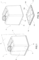
figure 1 shows an internally hollow body; -
figure 1a shows an exploded view of the internally hollow body; -
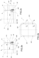
figure 2a shows a plan view from below of an internally hollow body; -
figures 2b and 2c show a detailed enlargement of an area C infigure 1 , obtained from a section of the internally hollow body offigure 1 along a vertical plane K, respectively, when said plane K is in correspondence with the section plane A-A and B-B infigure 2a ; -
figures 2d and 2e show a detailed enlargement of an area C infigure 1 , obtained from a section of the internally hollow body offigure 1 along a vertical plane K, respectively, when such plane K is in correspondence with the section plane A-A and B-B infigure 2a ; -
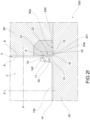
figure 2f shows a detailed enlargement of a vertical cross-section of the internally hollow body, when the internally hollow body is inserted between the punch and the die during an overmolding step of a joining element between a main body and a closure body of an internally hollow body; -
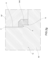
figure 2g shows a detailed enlargement of a section of a main body of the internally hollow body, when the main body is inserted between the punch and the die during a molding step of such main body; -
figures 3a to 3i illustrate the steps of the production method of the internally hollow body, by using an example of themold 500; -
figures 4a to 5e show the steps of the production method of the internally hollow body by using another example of themold 500. - In accordance with the accompanying figures, an internally hollow plastic body having an
inner cavity 2, preferably adapted to contain liquid, solid or gaseous material is collectively indicated at 1. - The term "internally" means that the
cavity 2 of the hollow body is internal to the body, which is to say that, for example, the body has an inner surface that defines, at least partially, such cavity and that is in contact with a liquid, solid or gaseous material that flows, or is contained, at least partially, in the cavity, and an outer surface of the hollow body that instead is in contact with the external environment or, for example, with a different or other element with respect to the one contained, or that flows, in the cavity. This type of internally hollow bodies includes, for example conduits, channels, pipes or container bodies. - The internally
hollow body 1 comprises amain body 4 shaped so as to compriseside walls 6, having aninner surface 8 which at least partially defines saidcavity 2 and which ends with ashaped edge 10 which delimits an engagement opening 12 to thecavity 2. The internallyhollow body 1 further comprises aclosure body 14, comprisingside closure walls 16 having aninner sealing surface 18. Suchinner sealing surface 18 is engaged at least partially with theinner surface 8 of theside walls 6 of themain body 4, and theclosure body 14 at least partially closes thecavity 2 at the engagement opening 12. - According to the invention, for example,
such closure body 14 is the bottom of a container, as in the embodiment shown infigure 1 and figure 1a , or the cover, as in the embodiment shown in the documentWO2016092407 , or one of the two half-shapes that, when joined, form the entire internally hollow body, or simply a portion of the internally hollow body or an ancillary portion (for example a handle of a container, an inlet mouth and the like). - Additionally, the internally
hollow body 1 comprises a joiningelement 20, also made of plastic, having the function of securely joining themain body 4 and theclosure body 14. - Preferably, the plastic material with which the joining
element 20 is made is adapted to fuse and weld with the plastic material with which themain body 4 or theclosure body 14 is made. For example, the joining element is made of the same plastic material as themain body 4 and/or theclosure body 14 or with a different plastic but one adapted to fuse with the plastic of theclosure body 14 and/or of themain body 4. - The term plastic material or plastic means a polymer, for example a synthetic resin, or an elastomer, or a thermoplastic or thermosetting polymer preferably selected from the group of polyethylenes, polypropylenes, methacrylates, polycarbonates or polyamides.
- Between the
main body 4 and theclosure body 14, there is anovermolding seat 22, and the joiningelement 20 is overmolded by injection to themain body 4 and theclosure body 14, covering such overmoldingseat 22. - Preferably, the
main body 4 is joined to theclosure body 14 at least partially along theshaped edge 10 by means of said joiningelement 20 or preferably along the entireshaped edge 10. - The overmolding of the joining
element 20 on theclosure body 14 and on themain body 4 occurs by injection molding, for example through a step of injection molding of a synthetic resin melted in the overmoldingseat 22, when theclosure body 14 and themain body 4 are mutually engaged and inserted in amold 500 for overmolding the joiningelement 20. - Preferably, the
closure body 14 is adapted to close completely and sealingly thecavity 2, at the engagement opening 12. In this way, hollow containers are created able to contain, for example, liquid, solid or gaseous substances, such as vials, barrels, jerrycans, flasks, bins, tanks, floats, buoys, lifebuoys, fenders, small cisterns, or bottles, wherein theclosure body 14 is preferably the bottom or the cover of such containers. In the case of internally hollow bodies for which, once closed, it is not necessary to access the inner cavity again, such as floats, buoys, lifebuoys or fenders, theclosure body 14 and themain body 4 respectively represent each of the two half-shells (preferably equal to each other) to be joined by the joining element to form the buoy, float, lifebuoy or fender. - The
closure body 14 has, moreover, amold engagement cavity 30 in which amold 500 for injection molding or a part thereof is adapted to counteract the pressure generated in the overmoldingseat 22 by injection means during an overmolding step of the joiningelement 20 and is at least partially couplable by shape-coupling. Thismold engagement cavity 30 is preferably formed externally of thecavity 2 of thehollow body 1, i.e. it is at least partially delimited from the outer surface of the closure body opposite the inner surface facing thecavity 2 of thehollow body 1. In other words, themold engagement cavity 30 is arranged on the opposite side with respect to theinner cavity 2 of the hollow body and is defined at least in part (or totally) by the outer surface adapted to be in contact with the external environment or in any case with a different element than that which is contained or flows into the cavity 2 (i.e. themold engagement cavity 30 does not face into the cavity 2). For example, suchmold engagement cavity 30 is delimited by theouter closure surface 17 of theside closure walls 16 of the closure body, opposite theinner sealing surface 18 towards themold engagement cavity 30. In this way, one avoids that, during the overmolding step, the injection of the resin forming the joiningelement 20, causes a disengagement between theinner sealing surface 18 of theclosure body 14 and theinner surface 8 of theside walls 6 themain body 4. - Preferably, as shown for example in
figure 2f , theouter closure surface 17 that defines themold engagement cavity 30 faces the opposite side with respect to thecavity 2. It follows that themold 500 engages themold engagement cavity 30 externally with respect to thecavity 2 of thehollow body 1 obtained at the end of the molding step. In this way, the molding steps are reduced, and it is also possible to produce totally closedhollow bodies 1. In effect, if themold engagement cavity 30 were formed in thecavity part 2 of thehollow body 1, in the case of totally closed hollow bodies, the mold portion inside themold cavity 30 and thecavity 2 would not allow the total closure of thehollow body 1. In effect, in this latter case, it would be necessary to leave an access to thecavity 2 free for removing the overmolding mold 500 (or part of it, for example, the die or the punch). - The
inner sealing surface 18 of theclosure body 14 is engaged at least partially in abutment with theinner surface 8 of themain body 4 along the engagement portion 8' of suchinner surface 8 in such a way as to counteract a mechanical stress between theclosure body 14 and themain body 4 along a preferential direction X' (for example a main vertical direction of extension of the hollow body) and in the direction of insertion of theclosure body 14 in theinner cavity 2. In other words, the engagement between theinner sealing surface 18 and the inner surface of themain body 4 allows any compressive stress between theclosure body 14 and themain body 4 to be distributed along theside walls 6 of the main body. This advantageously allows any impulsive loads acting between themain body 4 and theclosure body 14, for example, the hollow body accidental falling, to be supported. For example, in the case wherein thehollow body 1 is a jerrycan containing liquid, the mechanical stress along the preferential direction X', due to the jerrycan accidently falling with impact on theclosure body 14, would be directly distributed by theclosure body 14 to theside walls 6 of themain body 4, ensuring greater impact strength. - Preferably, advantageously, the engagement portion 8' is an engagement surface inclined with respect to the preferential direction X', even more preferably perpendicular to the preferential direction X'. For example, the engagement portion 8' is the rise of a
step 81 formed on theside walls 6 of themain body 4. - Preferably, moreover, the
inner sealing surface 18 of theclosure body 14 comprises an abutment portion 18', inclined (preferably perpendicular) with respect to the preferential direction X' and sealingly resting on the engagement portion 8' of themain body 4. This allows both a sealed joint to be obtained between theclosure body 14 and the main body 4 (particularly advantageous in the case of hollow bodies of solid, liquid or gaseous substances) and any mechanical stress to be distributed along an extended contact surface. - In accordance with the invention, the joining
element 20 is contained along its sides between theside walls 6 of the main body and theside closure walls 16. In this way, the joining element remains hidden from the view of an observer looking at the hollow body along a direction perpendicular to the side walls. Moreover, preferably, having defined a transverse plane P perpendicular to the preferential direction X' (for example perpendicular to the side walls 6), the joiningelement 20 is in contact with the external environment only along anouter surface 201, having at least a virtual tangent plane V parallel to said transverse plane P. In other words, for example in the case of a container or a jerrycan, the joiningelement 20 is preferably in contact with the outside only along a surface thereof facing outwards on the opposite side of the bottom of the container or the jerrycan (for example as shown infigures 2a to 2f ). - Preferably, the
outer surface 201 of the joining element is in contact with the outside in a discontinuous manner, i.e. only in regions spaced from one another, as shown for example infigure 2a . In other words, the joining element is totally contained between theside walls 6 of the main body and theside closure walls 16 of the main body, except at such regions spaced apart from one another in contact with the external environment. In particular, these spaced regions of the outer surface 21 are preferably located at the entry points of the resin during the overmolding step of the joiningelement 20 inside themold 500. - In one embodiment (for example shown in
figure 2f ), the joiningelement 20 is in contact with the external environment only along itsouter surface 201, flat and parallel to said transverse plane P. - Furthermore, guide
ribs 140 are preferably formed on theclosure body 14, adapted to guide theclosure body 14 during the step of coupling with themain body 4 towards theinner cavity 2. Preferably, the guide ribs are spaced from one another and protrude from themain body 14 towards theinner cavity 2. Moreover, preferably, theguide ribs 140 comprise aninclined surface 141 adapted to slide along an edge of theside walls 6 of the main body during the coupling step. Suchinclined surface 141 is, for example, connected to the abutment portion 18', so as to facilitate the engagement of theclosure body 14 during the insertion step in themain body 4 until it abuts the abutment portion 18' with the engagement portion 8' of themain body 4. - The internally
hollow body 1 described up to now may be obtained by means of themold 500 and through a production method according to the continuation of the present description. -
Mold 500 means a mold for injection molding, for example formed of two or more half-molds, for example a punch 50' and a die 50'', each bearing an impression designed to engage according to shape-coupling with themain body 4 or with theclosure body 14. For example, themain body 4 is inserted in the die 50" of theovermolding mold 500 according to shape-coupling and theclosure body 14 is inserted into the punch 50' of themold 500 according to shape-coupling. Preferably, a part of the walls forming the punch and/or a part of the walls forming the die are adapted to counteract the pressure generated on theovermolding seat 22 by the injection means during an overmolding step of the joiningelement 20. - Preferably, a die wall or only a
punch wall 50a (and not both at the same time) is in contact with the synthetic resin during the overmolding step of the joining element, and, in addition to counteracting the pressure during the step of injecting the synthetic resin, such die or punchwall 50a defines an outer closure wall of the overmolding seat of the joining element. In this way, once the overmolded synthetic resin has solidified, at such outer closure wall of the overmolding seat, theouter surface portion 201 of the joiningelement 20 is formed. In this way, the joiningelement 20 is contained along its sides between theside walls 6 of the main body and theside closure walls 16, avoiding making the structure of themold 500 complex. - In one case, the
mold engagement cavity 30 comprises anabutment surface 50 adapted to receive in abutment a portion of the mold and side walls forming theouter closure surface 17 on which themold walls 51 are at least partially engaged to counteract the pressure generated by the injection means during the overmolding step of the joiningelement 20. - Preferably, the
mold engagement cavity 30 has an annular shape with a "U" cross-section. - Preferably, the joining
element 20 completely fills theovermolding seat 22, so as to allow stable welding between themain body 4 and theclosure body 14. - Preferably, moreover, the overmolding seat 22 (and therefore the joining
element 20, once molded), is delimited both on the top and on the side by theinner surface 8 of theside walls 6 of themain body 4 and, on the side facing theinner cavity 2, by theside closure walls 16. - Moreover, preferably, the joining
element 20, annularly wraps thehollow body 1, creating a sealing welded ring between themain body 4 and theclosure body 14. - In the case wherein the
closure body 14 or themain body 4 also acts as the bottom of a container, suchmain body 4 or theclosure body 14 comprises a bottom wall, preferably integral with theside closure walls 16, having anupper bottom surface 15a, which faces thecavity 2 of the container and which constitutes the inner bottom surface of the container. The bottom wall 15 further comprises an outerbottom surface 15b, opposite theupper bottom surface 15a, not communicating with thecavity 2, but facing the outside of the container. - In one other case, the internally
hollow body 1 comprises at least one reinforcingwall 300, arranged transversely between twowalls mold engagement cavity 30. - According to the present invention, the method for producing the plastic, internally hollow body provides for joining the
main body 4 and theclosure body 14 in the same step wherein occurs the molding of a second closure body 14' and/or of a second main body to be used in a subsequent union step to obtain a second internally hollow body. - Preferably, the production of an internally
hollow body 1 according to the present invention is defined inindependent claim 3. - Preferably, the
main body 4 shaped in plastic and theclosure body 14 are made by injection molding. - Furthermore, it is provided that in the
mold engagement cavity 30 of theclosure body 14 or of themain body 4, themold 500 is inserted at least partially according to shape-coupling with themold engagement cavity 30 of theclosure body 14 or of themain body 4 in such a way that at least one of the walls of the mold counteracts the pressure generated on theovermolding seat 22 by the injection of natural or synthetic resin by the injection means during the overmolding step of the joiningelement 20. - Preferably, the overmolding step of the joining
element 20, provides that the molten synthetic resin which, once solidified, constitutes the joiningelement 20, is injected into themolding seat 22 at high temperature, while themain body 4 and theclosure body 14 are inserted into themold 500. In this step, when the molten resin at high temperature comes into contact with the walls of the overmolding seat 22 (for example, theinner sealing surface 18 of theside closure walls 16, theinner surface 8 of theside walls 6, the shaped edge 10), it causes the onset of fusion on the surface, i.e., a new transition of state from solid to molten form, allowing an effective and complete welding of the joiningelement 20 with themain body 4 and with theclosure body 14 due to the fusion of the materials and the subsequent resolidification step. - Referring now to
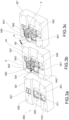
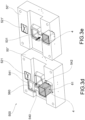
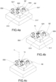
figures 3a to 5e , the internally hollowplastic body 1 is made by injection molding in a single mold comprisingmultiple cavities multiple cavities impressions mold 500. Thecavities mold 500 is closed by putting the respective die impressions and the punch impressions together. In each group offigures 3a to 3e and5a to 5e , a variant embodiment of the die 50" of themold 500, coupled with respective punch variants 50', shown infigures 3f to 3i and4a to 4m respectively, is illustrated according to a coupling clearly understandable to the person skilled in the art, executable in a cyclic and continuous way. In other words,figures 3a to 3e show the steps of the method on the die 50" side andfigures 3f to 3i show the steps of the method on the punch 50' side.Figures 4a to 4m show the steps of the punch 50' side method andfigures 5a to 5e show the steps of thedie side method 50". - The production method of the
hollow body 1 comprises the steps of: - a) molding a first
main body 4 in amain cavity 530 of saidmultiple cavities first closure body 14 in aclosure cavity 520 of saidmultiple cavities figure 3a on the punch infigure 3f , or the punch infigure 4a on the die infigure 5a ); - b) opening the
mold 500; - c) transferring the first
main body 4 from amain impression 531, 531' of such dieimpressions union impression 511, 511' of such dieimpressions element 540 which carries the first main body 4 (for example, as shown infigures 3b to 3e or5b to 5e ); - d) engaging the movable shaped
element 540 with the die 50" or with the punch 50' of themold 500 so that such movable shapedelement 540 forms a portion of themain impression 531, 531' of themain cavity 530 when the mold is closed for molding (for example, as illustrated infigures 3e and5e ); - e) in a same step, i.e. keeping the mold closed, molding a second closure body 14' in the
closure cavity 520 and joining the firstmain body 4 and thefirst closure body 14 in theunion cavity 510 of saidmultiple cavities figure 3e on the punch infigure 3h , or of the punch infigure 4e on the die infigure 5e or the punch infigure 4i on the die infigure 5e , or the punch infigure 4m on the die infigure 5e ). - It is clear that resin is injected into the
main cavity 530 to generate themain body 4 and resin is injected into theclosure cavity 520 to generate theclosure body 14. - In the
union cavity 510, the resin is injected into theovermolded seat 22 to overmold the joiningelement 20 between themain body 4 and theclosure body 14. - Moreover, "same step" means that the union between the
first closure body 14 and the firstmain body 4 takes place without opening the mold before the molding of the second closure body 14' has been completed. In other words, when themold 500 is closed, the plastic resin is injected both to overmold the joining element between themain body 4 and theclosure body 14 in theunion cavity 510, and to mold a second closure body 14' in theclosure cavity 520 to be used in a subsequent union (overmolding) step. For example, this is permitted due to an injection device inside the mold (not shown but known to the person skilled in the art) adapted to inject the polymer resin both into themain cavity 530 and into theunion cavity 510 and into theclosure cavity 520. Furthermore, this is also permitted by the use of a bi-injection press if it is decided to join the two half-shells with a different or other colored material. - Preferably, even more advantageously, in step e) it is also envisaged to mold a second main body to be used in the subsequent union (overmolding) step with the second closure body 14'.
- Preferably, moreover, the injection of polymer resin for the molding of the second main body, of the second closure body 14' and for the overmolding of the joining
element 20 between the firstmain body 4 and the first closure body takes place sequentially or simultaneously in themain cavity 530, theclosure cavity 520 and theunion cavity 510. - As previously described, the union of the first
main body 4 and thefirst closure body 14 takes place by injection overmolding of a joiningelement 20 along theovermolding seat 22. - Preferably, the movement of the movable shaped
element 540 comprises the step of rotating theshaped element 540 about an axis of rotation X and translating such movable shapedelement 540 along a direction of extraction of themain body 4 from the die 50" or from the punch 50'. - Preferably, before step c) the movable shaped
element 540 is engaged with the die 50" or with the punch 50' so as to form at least partially (and therefore not totally), the main impression 531 (as for example illustrated infigures 3a and5a ). - Preferably, moreover, the method comprises the step of:
d1) engaging the movable shapedelement 540 with the die 50" or with the punch 50' of themold 500 so that the movable shapedelement 540 forms a portion of theunion impression 511 of theunion cavity 510 when the mold is closed for molding. - In certain circumstances, step d1) is carried out substantially simultaneously with step d). In other words, the movable shaped
element 540 engages both with theunion cavity 510 and with themain cavity 530 so as to form a portion of theunion impression 511 and a portion of themain impression 531 when the mold is closed for molding. It is therefore clear that the movable shapedelement 540 engages both with theunion cavity 510 and with themain cavity 530 in such a way as to form only a portion of theunion impression 511 and only a portion of themain impression 531, and not the totality of theimpression 511 and/or of themain impression 531, when the mold is closed for molding. - The
mold 500 comprises: - a die 50" comprising a
main die impression 531, adie union impression 511 and adie closure impression 521; - a punch 50' comprising a main punch impression 531', a union punch impression 511' and a punch closure impression 521'.
- The punch impressions 511', 521', 531' and the
die impressions multiple molding cavities - The
mold 500 further comprises a movable shapedelement 540 movable for transferring the firstmain body 4 from the main impression of the die 531 or of the punch 531' to the union impression of the die 511 or of the punch 511'. Moreover, such a movable shapedelement 540 is adapted to engage with the die 50" or with the punch 50' of themold 500 so as to form at least a portion of the main impression of the die 531 or of the punch 531'. - Preferably, the movable shaped
element 540 is adapted to engage with the die 50" or with the punch 50' so as to form at least a portion of the union impression of the die 511 or of the punch 511'. - In certain circumstances, the movable shaped
element 540 comprises aunion portion 541 and amain portion 542 joined together by a connectingportion 543. Theunion portion 541 and themain portion 542 are adapted to engage with the union impression of thedie 511 and with the main impression of the die 531 or with the union impression of the punch 511' and with the main impression of the punch 531'. - The movable shaped
element 540 is adapted to engage with the die 50" or with the punch 50' so as to form only a portion of the union impression of the die 511 or the punch 511'. - Preferably, the
union portion 541 and themain portion 542 each comprise a frame 541', 542' which surrounds a housing 541'', 542'' adapted to receive themain body 4 therein. Such frame 541', 542'' is adapted to engage with the punch or with the die to form a portion of the union impression and/or the main impression of the punch or the die. - The possibility of moving only a portion of the union impression and/or the main impression of the punch or die allows reduced inertias to be obtained during the movement and therefore higher speeds of movement (for example of rotation), as well as require less power of the movement actuator means.
- In one case, the
frame 541', 541" comprises aninner side surface 560, which faces the housing 541'', 542''. Suchinner side surface 560 is shaped in such a way as to engage with theouter side surface 61 of the main body 4 (for example the outer surface of the side walls 6). Suchouter side surface 61 is the surface of the main body which faces away from theinner cavity 2 of thehollow body 1. - In one case, the shaped
movable element 540 is rotatable about an axis of rotation X parallel to the direction of movement of the die 50" and of the punch 50' in the closing/opening of themold 500. Such movable shapedelement 540 is moreover translatable along the extraction direction of themain body 4 from the die or the punch. - In one case, the punch 50' comprises a
rotating base 550, rotatable about a base axis of rotation Y. On suchrotating base 550 are supported the punch union impression 511' and the punch closure impression 521'. - In one case, the rotating
base 550 is arranged about the main punch impression 531'. Preferably, the base axis of rotation Y passes through the main impression of the punch 531'. Still more preferably, the rotatingbase 550 is in the shape of a circular crown arranged around the main impression of the punch 531'. Moreover, preferably, the base axis of rotation Y coincides with the central axis Z of themold 500. - With more detailed reference to
figures 3a to 3i , in order to obtain the internallyhollow body 1, it is envisaged to mold first themain body 4 and the closure body 14 (closing the die infigure 3a on the punch infigure 3f ). After having opened the mold, by means of the movable shapedelement 540, themain body 4 is extracted from the main impression 531 (figure 3b ), and the main body (figure 3c ) is rotated to insert it into the union impression 511 (figures 3d, 3e ). On the punch side 50', the rotating base 550 (figures 3g ,3h ) is moved so as to bring theclosure body 14 into a position corresponding to the union cavity 510 (figure 3h ). Subsequently, themold 500 is closed (the die infigure 3e with the punch infigure 3h ). Themain body 4 and theclosure body 14 engage with each other and the joiningelement 20 is overmolded by injection in theunion cavity 510 and at the same time a second closure body 14' is molded into theclosure cavity 520 and a second main body is molded in themain cavity 530; then the mold is opened (figure 3i ) and the finishedhollow body 1 is picked up. At this point, the molding resumes again cyclically with the extraction of the second main body from the main impression 531 (figure 3b ) and with the movement of the rotating base 550 (figures 3g ,3h ) so as to bring the second closure body 14' into the position corresponding to the union cavity 510 (figure 3h ) and so on. - In
figures 4a to 4m , the rotatingbase 550 is arranged adjacent to the main punch impression 531'. - Preferably, the base axis of rotation Y does not pass through the main punch impression 531'.
- Preferably, the base axis of rotation Y is spaced with respect to the central axis of the
mold 500. In this case, advantageously, by means of a simple rotation, the finishedhollow body 1 is positioned in a position further from the center of the mold, towards the periphery of the mold, guaranteeing an easier and more convenient pick-up of the finished piece. - With more detailed reference to
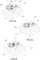
figures 4a to 5e , in order to obtain the internallyhollow body 1 it is envisaged to mold first themain body 4 and the closure body 14 (by closing the die infigure 5a on the punch infigure 4a ). After having opened the mold, themain body 4 is extracted from the main impression 531 (figure 5b ) by means of the movable shapedelement 540, and the main body (figure 5c ) is rotated to insert it into the union impression 511 (figures 5d, 5e ). On the punch side 50', the rotating base 550 (figures 4b to 4e ) is moved so as to bring theclosure body 14 into a position corresponding to the union cavity 510 (figure 4e ). Preferably, the rotatingbase 550 is moved by means of a first translation movement along the base axis of rotation Y adapted to detach theclosure body 14 from the closure impression 521' of the punch. Rotating means of the rotating base then move the base about the base axis of rotation Y to bring theclosure body 14 to correspond with the union cavity 510 (figure 4d ). Subsequently, translation means of therotating base 550 move the rotatingbase 550 with a second translation movement in the direction opposite to the first translation movement along the base axis of rotation Y (figure 4e ). - Contrary to the disclosure of
figures 3f to 3i wherein the closure impression 521' rotates integrally with the rotatingbase 550, the closure impression 521' is fixed and integrally supported by a base body 55' of the punch 50', separate from the rotating base. In this case, the rotatingbase 550 acts only as a transport tray for theclosure body 14, allowing a reduction of the total mass of the base to be rotated and the relative inertial moments during rotation. Advantageously, this allows the torque that the rotating means must deliver to rotate the rotating base to be reduced, with a consequent reduction of the dimensions of the rotation means, an increase in the speed of variation of the rotation (and of the molding times) and simplification of the mold structure. Subsequently, themold 500 is closed (the die infigure 5e with the punch infigure 4e ). Themain body 4 and theclosure body 14 engage with each other and the joiningelement 20 is overmolded by injection in theunion cavity 510 and at the same time a second closure body 14' is molded in theclosure cavity 520 and a second main body in themain cavity 530; then, the mold is opened (figure 4f ). At this point, the molding resumes again cyclically with the extraction of the second main body from the main impression 531 (figure 5b ) and with the movement of therotating base 550 as already described previously (figures 4g to 4i ), so as to bring the second closure body 14' into the position corresponding to the union cavity 510 (figure 4 ) and so on (figure 4j to 4m ). - Innovatively, the internally
hollow body 1 due to the particular configuration of engagement between the closure body and the main body and to the disposition of the joining element, allows any impulsive and compression loads acting on the hollow body to be resisted in a more robust manner and at the same time maintains a pleasant overall aesthetic of the product by not showing the unsightly joining element. - Moreover, the production method of the internally
hollow body 1 described in the preceding paragraphs, allows several types of internally hollow bodies (for example containers) to be made mainly for the food, chemical or petrochemical sectors, or for cleaning or pharmaceutical sectors, or for glues or paints or solvents, or for the boating or gardening sectors. - In particular, the method according to the present disclosure allows internally hollow bodies for injection molding to be made in a more efficient manner, due to the union between the main body and the closure body and to the simultaneous molding of a second closure body, usable in the subsequent union cycle for overmolding.
- Advantageously, therefore, the method allows one to combine, on the one hand, the advantages of injection molding techniques with respect to blow molding or rotational molding techniques, and on the other it allows one to speed up the production, increasing efficiency. This allows both the range of shapes and finishes of internally hollow bodies that may be achieved to be expanded and the manufacture process to be improved.
- Advantageously, moreover, the production method of internally hollow bodies according to the present disclosure allows the parallelization of the molding process to be increased, due to the possibility of simultaneously molding several internally hollow bodies and at the same time multiple main bodies and closure bodies, eliminating at least the step of withdrawing the closure body (or of the main body) from the mold and the subsequent insertion into the mold intended for overmolding, "replacing it" with rotating operations of a movable shaped element and a rotating base. This makes it possible to move on to the overmolding phase of the joining element in a quicker and more automated manner and, therefore, with an improved productive efficiency.
- Moreover, since the movable element and the rotating base are relatively light devices, they do not require expensive and complicated handling means, which, however, are required in the case of rotating entire half-molds of greater weight and subject to greater inertias. In effect, due to the reduced inertias, the movable element and the rotating base may be moved more quickly, reducing the total molding times.
Claims (15)
- Internally hollow plastic body (1), having a cavity (2), preferably adapted to contain liquid, solid or gaseous material, comprising:- a main body (4) shaped so as to comprise side walls (6), having an inner surface (8) that at least partially defines said cavity (2) and comprising an engagement portion (8'), said inner surface (8) delimiting an engagement opening (12) with the cavity (2);- a closure body (14) comprising side closure walls (16) having an inner sealing surface (18), said closure body (14) closing at least partially the cavity (2) at the engagement opening (12);- a joining element (20) made of plastic, which joins the main body (4) to the closure body (14), said joining element (20) covering an overmolding seat (22) between the main body (4) and the closure body (14);wherein the closure body (14) has a mold engagement cavity (30) in which a mold (500) for injection molding can be at least partially coupled by shape-coupling, adapted to counteract the pressure generated in the overmolding seat (22) by injection means during an overmolding step of the joining element (20),and wherein the inner sealing surface (18) of the closure body (14) is engaged at least partially in abutment with the inner surface (8) of the main body (4) along the engagement portion (8') in such a way as to counteract a mechanical stress between the closure body (14) and the main body (4) along a preferential direction (X') and in the direction of insertion of the closure body (14) in the inner cavity (2),characterized in that the joining element (20) is contained along its sides between the side walls (6) of the main body and the side closure walls (16).
- Internally hollow body (1) according to claim 1, wherein, having defined a transverse plane (P) perpendicular to the preferential direction (X'), said joining element (20) is in contact with the external environment only along an outer joining element surface thereof (201), said outer surface (201) having at least one virtual tangent plane (V) parallel to said transverse plane (P).
- Method for the production of an internally hollow plastic body (1) according to any one of the preceding claims, by injection molding in a mold (500) comprising multiple cavities (510, 520, 530), each of said multiple cavities (510, 520, 530) being formed by approaching respective die impressions (511, 521, 531) and respective punch impressions (511', 521', 531') formed on the die (50") and on the punch (50'), respectively, of the mold (500), the method comprising the steps of:a) molding a first main body (4) in a main cavity (530) of said multiple cavities (510, 520, 530) and a first closure body (14) in a closure cavity (520) of said multiple cavities (510, 520, 530);b) opening the mold (500);c) transferring the first main body (4) from a main impression (531, 531') of said die (511, 521, 531) or punch (511', 521', 531') impressions to a union impression (511, 511') of said die or punch impressions by moving a movable shaped element (540) which carries the first main body (4);d) engaging the movable shaped element (540) with the die (50") or with the punch (50') of the mold (500) so that said movable shaped element (540) forms a portion of the main impression (531, 531') of the main cavity (530) when the mold is closed for molding;e) molding a second closure body (14') in the closure cavity (520) and, while keeping the mold closed, in the union cavity (510) of said multiple cavities (510, 520) overmolding by injection a joining element (20) between the main body (4) and the closure body (14) along an overmolding seat (22).
- Method according to claim 3, wherein the movement of the movable shaped element (540) comprises the step of rotating the movable shaped element (540) about an axis of rotation (X) and translating the movable shaped element (540) along a direction of extraction of the main body (4) from the die (50") or from the punch (50').
- Method according to any of claims 3 to 4, wherein before step c), the movable shaped element (540) is engaged with the die (50'') or with the punch (50') in such a way as to at least partially form the main impression (531).
- Method according to claim 5, wherein the movable shaped element (540) is engaged with the die (50'') or with the punch (50') in such a way as to not totally form the main impression (531), i.e. only partially.
- Method according to any one of claims 3 to 6, further comprising the step of:
d1) engaging the shaped element (540) with the die (50") or with the punch (50') of the mold (500) so that said movable shaped element (540) forms a portion of the union impression (511) of the union cavity (510) when the mold is closed for molding. - Method according to any one of claims 3 to 8, wherein in step e) a second main body is molded in the main cavity (530).
- Mold for the production of an internally hollow plastic body (1) according to claim 1 or 2, having an inner cavity (2), by injection molding of a main body (4), a closure body (14) and a joining element (20) between the main body and the closure body, comprising:- a die (50") comprising a main die impression (531), a die union impression (511) and a die closure impression (521);- a punch (50') comprising a main punch impression (531'), a punch union impression (511') and a punch closure impression (521');said punch impressions (511', 521', 531') and die impressions (511, 521, 531) being adapted to be placed side by side to form multiple molding cavities (510, 520, 530);said mold (500) comprising a movable shaped element (540) movable for transferring the first main body (4) from the main die (531) or punch (531') impression to the die union (511) or punch union (511') impression, said movable shaped element (540) being adapted to engage with the die (50") or with the punch (50') of the mold (500) so as to form at least a portion of the main die impression (531) or punch impression (531').
- Mold according to claim 9, wherein the movable shaped element (540) is adapted to engage with the die (50") or with the punch (50') of the mold (500) so as to form at least a portion of the die union impression (511) or punch union impression (511').
- Mold according to claim 9 or 10, wherein the movable shaped element (540) comprises a union portion (541) and a main portion (542) joined together by a connecting portion (543), wherein the union portion (541) and the main portion (542) are adapted to engage both with the die union impression (511) and the main die impression (531) or with both the punch union impression (511') and the main punch impression (531'),
and wherein the union portion (541) and the main portion (542) each comprise a frame (541', 542') which surrounds a housing (541", 542'') adapted to accommodate the main body (4) at its interior, said frame (541', 542'') being adapted to engage with the punch or with the die to form a portion of the union impression (511, 511') and/or of the main impression (531, 531') of punch or die. - Mold according to any one of claims 9 to 11, wherein the movable shaped element (540) is rotatable about an axis of rotation (X) parallel to the movement direction of the die and punch during the closing/opening of the mold, said movable shaped element (540) also being movable along an extraction direction of the main body (4) from the die or the punch.
- Mold according to any one of claims 9 to 12, wherein the punch (50') comprises a rotating base (550), rotatable about a basic axis of rotation (Y), on said rotating base (550) being supported or obtained the punch union impression (511') and the punch closure impression (521').
- Mold according to claim 13, wherein the rotating base (550) is arranged around the main punch impression (531').
- Mold according to claim 13, wherein the rotating base (550) is arranged next to the main punch impression (531'), the basic axis of rotation (Y) being spaced with respect to a central axis (Z) of the mold (500).
Applications Claiming Priority (2)
| Application Number | Priority Date | Filing Date | Title |
|---|---|---|---|
| IT102017000015088A IT201700015088A1 (en) | 2017-02-10 | 2017-02-10 | BODY CABLE INTERNALLY, ITS METHOD OF REALIZATION AND MOLD |
| PCT/IB2018/050807 WO2018146626A1 (en) | 2017-02-10 | 2018-02-09 | Internally hollow body, mold and method thereof |
Publications (3)
| Publication Number | Publication Date |
|---|---|
| EP3580032A1 EP3580032A1 (en) | 2019-12-18 |
| EP3580032B1 true EP3580032B1 (en) | 2024-09-04 |
| EP3580032C0 EP3580032C0 (en) | 2024-09-04 |
Family
ID=59067796
Family Applications (1)
| Application Number | Title | Priority Date | Filing Date |
|---|---|---|---|
| EP18709080.8A Active EP3580032B1 (en) | 2017-02-10 | 2018-02-09 | Internally hollow body, mold and method thereof |
Country Status (8)
| Country | Link |
|---|---|
| US (1) | US20200031030A1 (en) |
| EP (1) | EP3580032B1 (en) |
| CN (1) | CN110769997A (en) |
| BR (1) | BR112019016425A2 (en) |
| IT (1) | IT201700015088A1 (en) |
| MA (1) | MA47463A (en) |
| MX (1) | MX2019009569A (en) |
| WO (1) | WO2018146626A1 (en) |
Families Citing this family (1)
| Publication number | Priority date | Publication date | Assignee | Title |
|---|---|---|---|---|
| CN116423745B (en) * | 2023-03-30 | 2023-11-10 | 宁波永成双海汽车部件股份有限公司 | Wire harness board connector progressive die structure and production method thereof |
Family Cites Families (7)
| Publication number | Priority date | Publication date | Assignee | Title |
|---|---|---|---|---|
| JPS58116125A (en) * | 1981-12-29 | 1983-07-11 | Azumi Sangyo Kk | Manufacture of double wall container of synthetic resin |
| JPH11179754A (en) * | 1997-12-18 | 1999-07-06 | Nissan Motor Co Ltd | Injection welding molding method |
| DE60306514T8 (en) * | 2003-07-29 | 2007-11-29 | Toyoda Boshoku Corp., Kariya | Apparatus and method for the production of plastic hollow bodies |
| JP4441864B2 (en) * | 2004-08-04 | 2010-03-31 | 株式会社デンソー | Composite product manufacturing method and manufacturing apparatus |
| ES2586510T3 (en) * | 2009-09-10 | 2016-10-14 | Keter Plastic Ltd. | Injection molding process and article manufactured using said technique |
| FR2949994B1 (en) * | 2009-09-15 | 2011-10-21 | Sas Alain Massacrier | MOLD FOR TWO-PART INJECTION AND BODY ASSEMBLY |
| MA41149A (en) * | 2014-12-11 | 2017-10-17 | Umberto Nenna | INTERNALLY HOLLOW BODY, MOLD, AND CORRESPONDING MANUFACTURING PROCESS |
-
2017
- 2017-02-10 IT IT102017000015088A patent/IT201700015088A1/en unknown
-
2018
- 2018-02-09 CN CN201880024442.6A patent/CN110769997A/en active Pending
- 2018-02-09 WO PCT/IB2018/050807 patent/WO2018146626A1/en not_active Ceased
- 2018-02-09 US US16/484,652 patent/US20200031030A1/en not_active Abandoned
- 2018-02-09 BR BR112019016425A patent/BR112019016425A2/en not_active Application Discontinuation
- 2018-02-09 MA MA047463A patent/MA47463A/en unknown
- 2018-02-09 EP EP18709080.8A patent/EP3580032B1/en active Active
- 2018-02-09 MX MX2019009569A patent/MX2019009569A/en unknown
Also Published As
| Publication number | Publication date |
|---|---|
| BR112019016425A2 (en) | 2020-04-07 |
| WO2018146626A1 (en) | 2018-08-16 |
| EP3580032A1 (en) | 2019-12-18 |
| IT201700015088A1 (en) | 2018-08-10 |
| MA47463A (en) | 2019-12-18 |
| MX2019009569A (en) | 2019-12-09 |
| EP3580032C0 (en) | 2024-09-04 |
| CN110769997A (en) | 2020-02-07 |
| US20200031030A1 (en) | 2020-01-30 |
Similar Documents
| Publication | Publication Date | Title |
|---|---|---|
| EP3230171B1 (en) | Internally hollow body, mould and manufacturing method thereof | |
| EP2718196B1 (en) | A one-piece closure for equipping a container | |
| US8017065B2 (en) | System and method for forming a container having a grip region | |
| US5897823A (en) | Method of forming a plastic container component and the plastic container component formed by the method | |
| JP5693847B2 (en) | Molded lightweight plastic lid showing high strength | |
| US5820807A (en) | Staged, sequentially separated injection mold method for forming container closures | |
| CN101258076A (en) | Closures with isolation liners | |
| JPH04267739A (en) | Wide-mouthed plastic vessel, and manufacturing method therefor | |
| FR2733715A1 (en) | PROCESS FOR MANUFACTURING THERMOPLASTIC PARTS AND PARTS OBTAINED ACCORDING TO THIS PROCESS | |
| EP3580032B1 (en) | Internally hollow body, mold and method thereof | |
| FR2662144A1 (en) | Stopper with rigid lid, pivoting elastically, and flexible sealing ring with a pouring orifice, and its moulding method | |
| EP1694573B1 (en) | An improved tube made of a plastic material | |
| FR2752560A1 (en) | Injection mould plastic bottle top | |
| JP7481911B2 (en) | Multi-container manufacturing method | |
| US20040108627A1 (en) | Blown pet handleware for containers | |
| CN106414027B (en) | Composite container manufacturing method, molding die and composite container | |
| KR101959070B1 (en) | Dual container producing by blow molding | |
| JP6987702B2 (en) | Preform and manufacturing method of preform | |
| KR19980021275A (en) | Apparatus for manufacturing container filled with contents | |
| JP2018203350A (en) | Sealed container | |
| CN205221456U (en) | Beverage bottle safety anti -fake structure | |
| JP2021172058A (en) | Resin molded products and their manufacturing methods | |
| FR2786466A1 (en) | Bottle cap for still or effervescent liquid has tamperproof ring injection molded over annular shoulder at end of injection remainder of cap | |
| US20140225305A1 (en) | Hollow overlay molding process and system | |
| KR19980021276A (en) | Manufacturing method of container filled with contents |
Legal Events
| Date | Code | Title | Description |
|---|---|---|---|
| STAA | Information on the status of an ep patent application or granted ep patent |
Free format text: STATUS: UNKNOWN |
|
| STAA | Information on the status of an ep patent application or granted ep patent |
Free format text: STATUS: THE INTERNATIONAL PUBLICATION HAS BEEN MADE |
|
| PUAI | Public reference made under article 153(3) epc to a published international application that has entered the european phase |
Free format text: ORIGINAL CODE: 0009012 |
|
| STAA | Information on the status of an ep patent application or granted ep patent |
Free format text: STATUS: REQUEST FOR EXAMINATION WAS MADE |
|
| 17P | Request for examination filed |
Effective date: 20190905 |
|
| AK | Designated contracting states |
Kind code of ref document: A1 Designated state(s): AL AT BE BG CH CY CZ DE DK EE ES FI FR GB GR HR HU IE IS IT LI LT LU LV MC MK MT NL NO PL PT RO RS SE SI SK SM TR |
|
| AX | Request for extension of the european patent |
Extension state: BA ME |
|
| DAX | Request for extension of the european patent (deleted) | ||
| RAV | Requested validation state of the european patent: fee paid |
Extension state: TN Effective date: 20190905 Extension state: MA Effective date: 20190905 |
|
| STAA | Information on the status of an ep patent application or granted ep patent |
Free format text: STATUS: EXAMINATION IS IN PROGRESS |
|
| 17Q | First examination report despatched |
Effective date: 20200710 |
|
| GRAP | Despatch of communication of intention to grant a patent |
Free format text: ORIGINAL CODE: EPIDOSNIGR1 |
|
| STAA | Information on the status of an ep patent application or granted ep patent |
Free format text: STATUS: GRANT OF PATENT IS INTENDED |
|
| INTG | Intention to grant announced |
Effective date: 20240404 |
|
| GRAS | Grant fee paid |
Free format text: ORIGINAL CODE: EPIDOSNIGR3 |
|
| GRAA | (expected) grant |
Free format text: ORIGINAL CODE: 0009210 |
|
| STAA | Information on the status of an ep patent application or granted ep patent |
Free format text: STATUS: THE PATENT HAS BEEN GRANTED |
|
| AK | Designated contracting states |
Kind code of ref document: B1 Designated state(s): AL AT BE BG CH CY CZ DE DK EE ES FI FR GB GR HR HU IE IS IT LI LT LU LV MC MK MT NL NO PL PT RO RS SE SI SK SM TR |
|
| REG | Reference to a national code |
Ref country code: GB Ref legal event code: FG4D |
|
| REG | Reference to a national code |
Ref country code: CH Ref legal event code: EP |
|
| REG | Reference to a national code |
Ref country code: IE Ref legal event code: FG4D |
|
| REG | Reference to a national code |
Ref country code: DE Ref legal event code: R096 Ref document number: 602018073904 Country of ref document: DE |
|
| U01 | Request for unitary effect filed |
Effective date: 20240924 |
|
| U07 | Unitary effect registered |
Designated state(s): AT BE BG DE DK EE FI FR IT LT LU LV MT NL PT RO SE SI Effective date: 20241017 |
|
| PG25 | Lapsed in a contracting state [announced via postgrant information from national office to epo] |
Ref country code: NO Free format text: LAPSE BECAUSE OF FAILURE TO SUBMIT A TRANSLATION OF THE DESCRIPTION OR TO PAY THE FEE WITHIN THE PRESCRIBED TIME-LIMIT Effective date: 20241204 |
|
| PG25 | Lapsed in a contracting state [announced via postgrant information from national office to epo] |
Ref country code: PL Free format text: LAPSE BECAUSE OF FAILURE TO SUBMIT A TRANSLATION OF THE DESCRIPTION OR TO PAY THE FEE WITHIN THE PRESCRIBED TIME-LIMIT Effective date: 20240904 Ref country code: GR Free format text: LAPSE BECAUSE OF FAILURE TO SUBMIT A TRANSLATION OF THE DESCRIPTION OR TO PAY THE FEE WITHIN THE PRESCRIBED TIME-LIMIT Effective date: 20241205 |
|
| PG25 | Lapsed in a contracting state [announced via postgrant information from national office to epo] |
Ref country code: HR Free format text: LAPSE BECAUSE OF FAILURE TO SUBMIT A TRANSLATION OF THE DESCRIPTION OR TO PAY THE FEE WITHIN THE PRESCRIBED TIME-LIMIT Effective date: 20240904 |
|
| PG25 | Lapsed in a contracting state [announced via postgrant information from national office to epo] |
Ref country code: RS Free format text: LAPSE BECAUSE OF FAILURE TO SUBMIT A TRANSLATION OF THE DESCRIPTION OR TO PAY THE FEE WITHIN THE PRESCRIBED TIME-LIMIT Effective date: 20241204 |
|
| PG25 | Lapsed in a contracting state [announced via postgrant information from national office to epo] |
Ref country code: RS Free format text: LAPSE BECAUSE OF FAILURE TO SUBMIT A TRANSLATION OF THE DESCRIPTION OR TO PAY THE FEE WITHIN THE PRESCRIBED TIME-LIMIT Effective date: 20241204 Ref country code: PL Free format text: LAPSE BECAUSE OF FAILURE TO SUBMIT A TRANSLATION OF THE DESCRIPTION OR TO PAY THE FEE WITHIN THE PRESCRIBED TIME-LIMIT Effective date: 20240904 Ref country code: NO Free format text: LAPSE BECAUSE OF FAILURE TO SUBMIT A TRANSLATION OF THE DESCRIPTION OR TO PAY THE FEE WITHIN THE PRESCRIBED TIME-LIMIT Effective date: 20241204 Ref country code: HR Free format text: LAPSE BECAUSE OF FAILURE TO SUBMIT A TRANSLATION OF THE DESCRIPTION OR TO PAY THE FEE WITHIN THE PRESCRIBED TIME-LIMIT Effective date: 20240904 Ref country code: GR Free format text: LAPSE BECAUSE OF FAILURE TO SUBMIT A TRANSLATION OF THE DESCRIPTION OR TO PAY THE FEE WITHIN THE PRESCRIBED TIME-LIMIT Effective date: 20241205 |
|
| U20 | Renewal fee for the european patent with unitary effect paid |
Year of fee payment: 8 Effective date: 20250226 |
|
| PG25 | Lapsed in a contracting state [announced via postgrant information from national office to epo] |
Ref country code: IS Free format text: LAPSE BECAUSE OF FAILURE TO SUBMIT A TRANSLATION OF THE DESCRIPTION OR TO PAY THE FEE WITHIN THE PRESCRIBED TIME-LIMIT Effective date: 20250104 |
|
| PG25 | Lapsed in a contracting state [announced via postgrant information from national office to epo] |
Ref country code: SM Free format text: LAPSE BECAUSE OF FAILURE TO SUBMIT A TRANSLATION OF THE DESCRIPTION OR TO PAY THE FEE WITHIN THE PRESCRIBED TIME-LIMIT Effective date: 20240904 |
|
| PG25 | Lapsed in a contracting state [announced via postgrant information from national office to epo] |
Ref country code: ES Free format text: LAPSE BECAUSE OF FAILURE TO SUBMIT A TRANSLATION OF THE DESCRIPTION OR TO PAY THE FEE WITHIN THE PRESCRIBED TIME-LIMIT Effective date: 20240904 |
|
| PG25 | Lapsed in a contracting state [announced via postgrant information from national office to epo] |
Ref country code: CZ Free format text: LAPSE BECAUSE OF FAILURE TO SUBMIT A TRANSLATION OF THE DESCRIPTION OR TO PAY THE FEE WITHIN THE PRESCRIBED TIME-LIMIT Effective date: 20240904 |
|
| PG25 | Lapsed in a contracting state [announced via postgrant information from national office to epo] |
Ref country code: SK Free format text: LAPSE BECAUSE OF FAILURE TO SUBMIT A TRANSLATION OF THE DESCRIPTION OR TO PAY THE FEE WITHIN THE PRESCRIBED TIME-LIMIT Effective date: 20240904 |
|
| PLBE | No opposition filed within time limit |
Free format text: ORIGINAL CODE: 0009261 |
|
| STAA | Information on the status of an ep patent application or granted ep patent |
Free format text: STATUS: NO OPPOSITION FILED WITHIN TIME LIMIT |
|
| 26N | No opposition filed |
Effective date: 20250605 |
|
| PG25 | Lapsed in a contracting state [announced via postgrant information from national office to epo] |
Ref country code: MC Free format text: LAPSE BECAUSE OF FAILURE TO SUBMIT A TRANSLATION OF THE DESCRIPTION OR TO PAY THE FEE WITHIN THE PRESCRIBED TIME-LIMIT Effective date: 20240904 |
|
| REG | Reference to a national code |
Ref country code: CH Ref legal event code: PL |
|
| PG25 | Lapsed in a contracting state [announced via postgrant information from national office to epo] |
Ref country code: CH Free format text: LAPSE BECAUSE OF NON-PAYMENT OF DUE FEES Effective date: 20250228 |
|
| GBPC | Gb: european patent ceased through non-payment of renewal fee |
Effective date: 20250209 |
|
| PG25 | Lapsed in a contracting state [announced via postgrant information from national office to epo] |
Ref country code: GB Free format text: LAPSE BECAUSE OF NON-PAYMENT OF DUE FEES Effective date: 20250209 |
|
| PG25 | Lapsed in a contracting state [announced via postgrant information from national office to epo] |
Ref country code: IE Free format text: LAPSE BECAUSE OF NON-PAYMENT OF DUE FEES Effective date: 20250209 |
|
| U20 | Renewal fee for the european patent with unitary effect paid |
Year of fee payment: 9 Effective date: 20251230 |
|
| VS25 | Lapsed in a validation state [announced via postgrant information from nat. office to epo] |
Ref country code: MA Free format text: FAILURE TO ELECT DOMICILE IN THE NATIONAL COUNTRY Effective date: 20241205 |
|
| VS25 | Lapsed in a validation state [announced via postgrant information from nat. office to epo] |
Ref country code: MA Free format text: LAPSE BECAUSE OF FAILURE TO SUBMIT A TRANSLATION OF THE DESCRIPTION OR TO PAY THE FEE WITHIN THE PRESCRIBED TIME-LIMIT Effective date: 20240904 |